
ZIGRM400 - Plucker Zipper - Free user manual and instructions
Find the device manual for free ZIGRM400 Zipper in PDF.

| Product type | Poultry plucker |
| Brand | Zipper |
| Model | ZIGRM400 |
| Power supply | 230 V ~ 50 Hz |
| Power | Approx. 750 W |
| Capacity | Up to 2 poultry per cycle |
| Main functions | Plucking chickens, ducks, geese, turkeys |
| Drum material | Stainless steel |
| Plucking fingers | Rubber, mounted on plywood |
| Safety system | Magnetic safety switch, automatic stop |
| Water supply | 3/4" connection with shut-off valve |
| Waste water drainage | Drain hose ∅ 100 mm |
| Maintenance | Clean with water after each use, mild detergent |
| Warranty | 2 years non-commercial use, 1 year commercial use |
| Spare parts | Original Zipper parts available |
| Repairability | By authorized center; spare parts available |
| Included accessories | Transport wheels, 13 mm wrench, user manual |
| Weight | Approx. 25 kg |
| Dimensions (L×W×H) | Approx. 60 × 50 × 80 cm |
Frequently Asked Questions - ZIGRM400 Zipper
User questions about ZIGRM400 Zipper
0 question about this device. Answer the ones you know or ask your own.
Ask a new question about this device
Download the instructions for your Plucker in PDF format for free! Find your manual ZIGRM400 - Zipper and take your electronic device back in hand. On this page are published all the documents necessary for the use of your device. ZIGRM400 by Zipper.
USER MANUAL ZIGRM400 Zipper
natural_image
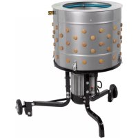
Exterior view of a cylindrical industrial device with mounting holes and three wheels (no text or symbols visible)ZI-GRM400
EAN 91420039233796

natural_image
Industrial machine with perforated top and three legs, no visible text or symbolsZI-GRM1100
EAN 9120039232713

natural_image
Industrial machine with three legs and a central cylindrical housing (no visible text or symbols)ZI-GRM1650
EAN 9120039234038
CE

1 INHALT / INDEX
1 INHALT / INDEX 2
11.1 Intended Use....20
11.2 Security instructions 20
11.3 Remaining risk factors....21
12 ASSEMBLY 22
12.1 Assembly ZI-GRM400 22
12.2 Assembly ZI-GRM1100 and ZI-GRM1650.... 24
13 OPERATION 27
13.1 Operation instructions....27
13.2 Operation 27
14 MAINTENANCE 27
14.1 Maintenance plan 28
14.2 Cleaning 28
14.3 Disposal....28
15 TROUBLE SHOOTING 28
16 PREDGOVOR (HR) 29
17 SIGURNOST 30
17.1 Namjenska uporaba....30
17.2 Upute o sigurnosti....30
17.3 Ostale opasnosti....31
18 MONTAŽA 32
18.1 Montaža ZI-GRM400 32
18.2 Sastavljanje ZI-GRM1100, ZI-GRM1650 34
19 RAD 37
19.1 Upute o radu....37
19.2 Rukovanje 37
20 ODRŽAVANJE 38
20.1 Servisiranje i plan održavanja 38
20.2 Čišćenje....38
20.3 Zbrinjavanje 38
21 UKLANJANJE POGREŠAKA 39
22 AVANT-PROPOS (FR) 40
23 SECURITE 41
EN CE-CONFORM: This product complies with EC-directives
HR CE SUKLADNOST: Ovaj proizvod ispunjava EU direktive
EN READ THE MANUAL! Read the user and maintenance manual carefully and get familiar with the controls in order to use the machine correctly and to avoid injuries and machine defects.
HR UPOZORENJE! Obratite pozornost na simbole za sigurnost! Nepoštivanje propisa i uputa za korištenje stroja može dovesti do teških ljudskih šteta i smrtnih opasnosti
EN ATTENTION! Ignoring the safety signs and warnings applied on the machine as well as ignoring the security and operating instructions can cause serious injuries and even lead to death.
HR UPOZORENJE! Obratite pozornost na simbole za sigurnost! Nepoštivanje propisa i uputa za korištenje stroja može dovesti do teških ljudskih šteta i smrtnih opasnosti.
EN Stop and pull out the power plug before any break and engine maintenance!
EN Protective clothing!
EN Operation with jewelry and long, open hair and loose clothing forbidden!
HR Zabranjeno je rukovanje s nakitom, raspuštenom kosom i širokom odjećom!

EN Warning of rotating parts tub!
HR Oprez! Rotirajući bubanj!
EN Warning against thrown-off items!
natural_image
Exploded view diagram of a mechanical assembly with layered components and a dashed arc indicating motion (no text or symbols)natural_image
Technical line drawing of a mechanical device with a square housing and a circular component mounted on a base (no text or symbols)This manual contains important information and advice for the correct and safe use and maintenance of the chicken plucker ZI-GRM400, ZI-GRM1100 and ZI-GRM1650.
Following the usual commercial name of the device (see cover) is substituted in this manual with the name "machine".
The manual is part of the machine and may not be stored separately. Read it profoundly before first use of the machine and keep it for later reference. When the machine is handed to other persons always put the manual to the machine.
Please follow the security instructions!
Please read the entire manual, to prevent misunderstandings, machine damage or even injuries!

Due to continuous development of our products illustrations, pictures might differ slightly.
If you however find errors in this manual, please inform us.
Technical changes excepted!
Copyright law
© 2018
This manual is protected by copyright law – all rights reserved. Especially the reprinting as well as the translation and depiction of pictures will be prosecuted by law. Court of jurisdiction is the Landesgericht Linz or the competent court for 4707 Schlüsslberg, AUSTRIA.
Customer Support
Should you return the plucker for various reasons, the machine must be thoroughly cleaned beforehand. If there are still poultry residues in the machine, the machine can not accepted!

11 SAFETY
11.1 Intended Use
The machine must only be used for its intended purpose! Any other use is deemed to be a case of misuse. To use the machine properly you must also observe and follow all safety regulations, the assembly instructions, operating and maintenance instructions lay down in this manual.
All people who use and service the machine have to be acquainted with this manual and must be informed about the machine's potential hazards.
It is also imperative to observe the accident prevention regulations in force in your area.
The same applies for the general rules of occupational health and safety.
The machine is used for:
Remove feathers from poultry
Any manipulation of the machine or its parts is a misuse, in this case ZIPPER-MASCHINEN and its sales partners cannot be made liable for ANY direct or indirect damage.
Prohibited use:
- The operation of the machine outside the stated technical limits described in this manual is forbidden.
• The operation of the machine without provided protective devices is prohibited - The use of the machine not being suitable for the use of the machine and not being certified is forbidden.
- Any manipulation of the machine and parts is forbidden.
• The unattended operation on the machine during the working process is forbidden!
• It is not allowed to leave the immediate work area during the work is being performed.
11.2 Security instructions
Missing or non-readable security stickers have to be replaced immediately!
The locally applicable laws and regulations may specify the minimum age of the operator and limit the use of this machine!
To avoid malfunction, machine defects and injuries, read the following security instructions!
- Keep your work area tidy! An untidy work area may cause accidents. Avoid slippery floor!
- Make sure the work area is lighted sufficiently!
• Work only in a well ventilated area! - Do not overload the machine!
- Provide good stability of the machine.
- Always stay focused when working. Reduce distortion sources in your working environment. The operation of the machine when being tired, as well as under the influence of alcohol, drugs or concentration influencing medicaments is forbidden!
- The machine must be operated only by trained persons (knowledge and understanding of this manual), which have no limitations of motor skills compared with conventional workers.
- Do not allow other people, particularly children, to touch the machine or the cable. Keep them away from your work area!
- Do not wear loose clothing or jewelry as they might be caught and cause severe accidents! Wear a hair net if you have long hair!
-
Loose objects can become entangled and cause serious injuries
-
Use personal safety equipment: safety goggles, work wear when working with or on the machine.
- Never leave the machine running unattended! Before leaving the working area switch the machine off and wait until the machine stops.
• Always disconnect the machine prior to any actions performed at the machine! - Avoid unintentional starting
- Do not use the machine with damaged switch
- The plug of an electrical tool must strictly correspond to the socket. Do not use any adapters together with earthed electric tools
- Each time you work with an electrically operated machine, caution is advised! There is a risk of electric shock, fire, cutting injury
- When working with the machine outdoors, use extension cables suitable for outdoor use
- Use power tools and machines never in the vicinity of flammable liquids and gases (danger of explosion)
- Check the cable regularly for damage
- Do not use the cable to carry the machine
- Protect the cable from heat, oil and sharp edges
- Avoid body contact with earthed components
- Do not put hands or feet near rotating parts or under the machine. Keep clear of the discharge openings at all times!
- Turn off machine and wait for a complete stop before removing poultry or feathers from the machine. Do not place arms, hands, or other body parts inside machine while processing or spinning.
- Never put live poultry into the machine. Slaughter, bleed and scald poultry properly before processing (scalding time: up to two minutes at 60 - 65°C, depending on the size of the animals).
11.3 Remaining risk factors

WARNING
It is important to know that each machine has residual risks.
In the execution of all work (even the simplest) greatest attention is required. Safe working always depends on you!
Even if the machine is used as required it is still impossible to eliminate certain residual risk factors totally. The following hazards may arise in connection with the machine's construction and design:
- Risk of injury to the hands / fingers by the rotating tub and hot water during operation.
- Risk of injury: hair and loose clothing, etc. can be captured and wound up! Safety regulations must be observed with regard to clothing.
- Risk of injury due to contacting with live electrical components.
- Risk of injury caused the tilting of the machine
- Risk of injury to the eye by flying debris, even with safety goggles.
- Risk of injury to the hearing by prolonged labor without hearing protection.
These risk factors can be minimized through obeying all security and operation instructions, proper machine maintenance, proficient and appropriate operation by persons with technical knowledge and experience!
12 ASSEMBLY
Please check the product contents immediately after receipt for any eventual transport damage or missing parts. Claims from transport damage or missing parts must be placed immediately after initial machine receipt and unpacking before putting the machine into operation. Please understand that later claims cannot be accepted anymore.
12.1 Assembly ZI-GRM400
 | 1. Unpack the machine as shown in the illustration on the left: Open the cardboard box, remove the polystyrene cover and place it upside down on a flat surface in your assembly area.Remove the motor / feather pan unit and place it in the polystyrene mould with the shaft pointing downwards (motor pointing upwards; shaft should be placed in the hole in the polystyrene mould). | |
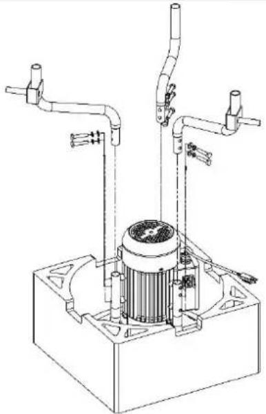 | NOTE: Each leg fits only for one position. The legs and axle brackets are marked A, B and C at the factory for easier mounting!2. Attach the legs to the motor / feather pan unit. Mount the leg marked A into the axle mount marked A etc. |
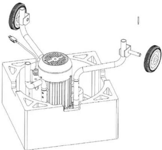 | 3. Slide a wheel followed by a washer onto one of the two axle brackets and secure with a cotter pin. Repeat procedure on the opposite side to mount the second wheel. |
 | 4. Take the motor/feather pan unit out of the polystyrene mould now and place it upright on its legs. |
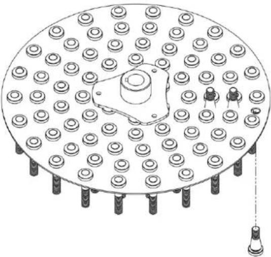 | 5. Remove the finger plate from the tub. Mount rubber finger into the opening on the underside of the finger plate. |
 | 6. Insert the key into the drive shaft.7. Lubricate motor shaft.Align keyway in finger plate with key in shaft and push down into place.8. Assemble M8 bolt, M8 lock washer and 8 mm domed spacer over shaft. Tighten with 13 mm wrench. |
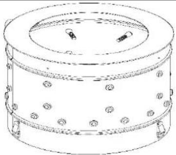  | 9. Place tub in feather pan.NOTE: The magnetic read switch in the feather pan must be aligned with the magnet in the tub. Align arrow label on tub to arrow on feather pan (note the marking).10. Fix the drum with the quick-release fasteners.sIt is recommended that you attach a valve to the tub. |
12.2 Assembly ZI-GRM1100 and ZI-GRM1650

natural_image
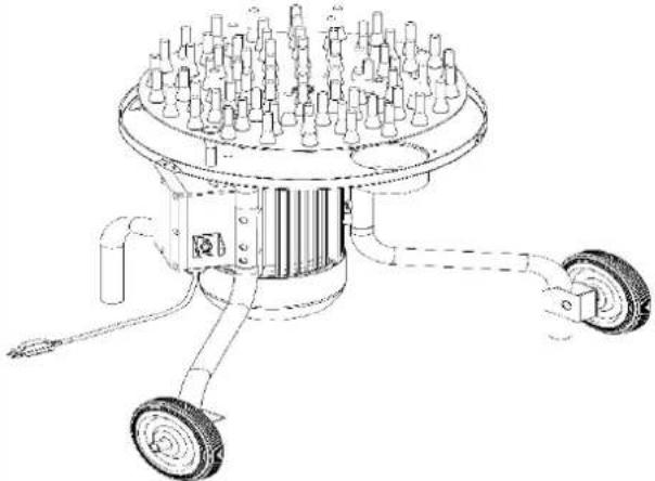
Technical diagram showing a multi-step assembly with a dashed arrow indicating process flow (no text or symbols)1. Unpack the machine (FIGURE 1)
natural_image
Technical line drawing of a mechanical device with a square base and a circular component mounted on a tripod (no text or symbols)-
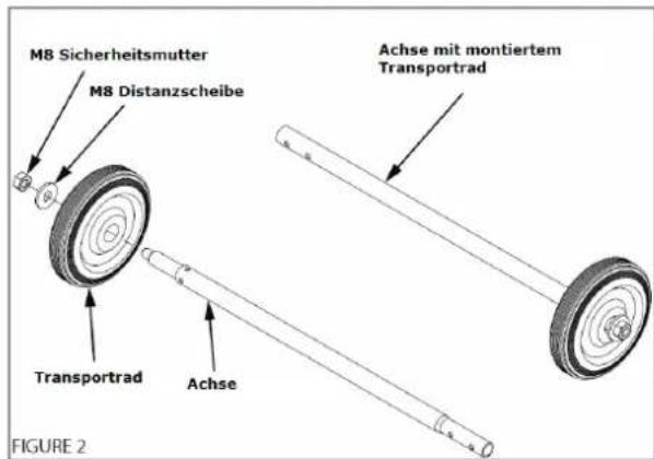
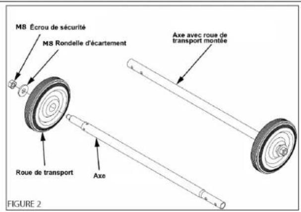
Mount the transport wheels on the axles (FIGURE 2).
-
Mount the feet on the machine frame (FIGURE 3). Move the long feet to the side of the motor and the short foot to the opposite position.
NOTE: Each stand is only suitable for one position. Make sure that the axle holders are parallel to each other!
-
Assemble axles with transport wheels (FIGURE 4 & 5).
-
Assemble axles with transport wheels (FIGURE 4 & 5)
-
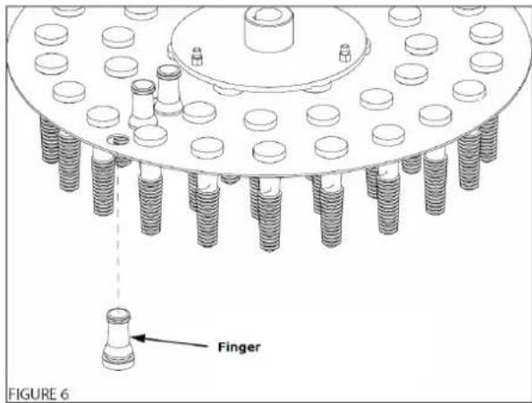
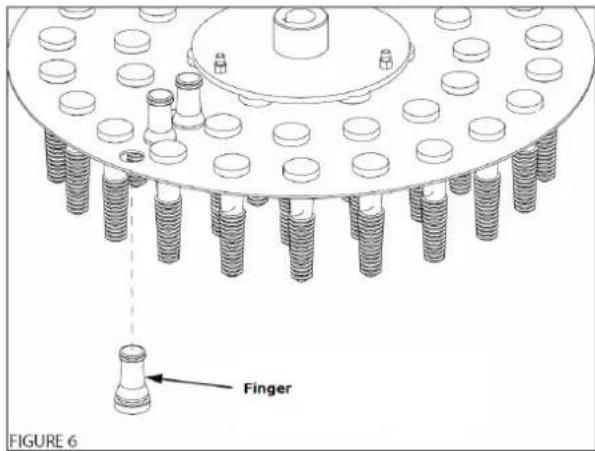
Remove the spring trough and mount the finger on the finger plate (FIGURE6)
-
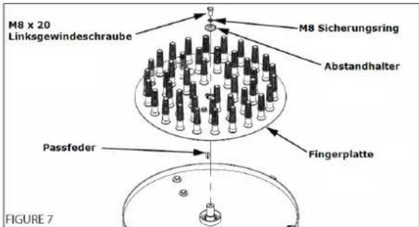
Mount the finger plate equipped with fingers back onto the motor shaft (FIGURE 7). Insert feather key into the motor shaft, slide on finger plate and fix with screws (M8x20 LEFT THREAD!).
-
Place the drum on the machine (FIGURE 8).
NOTE: The magnet must be positioned exactly above the Safety Switch. (note markings).
Fix the drum with the quick-release fasteners.
Fit out water connection "3/4" with a shut-off valve.
13 OPERATION
Device to be operated in a perfect state only. Inspect the device visually every time it is to be used. Check in particular the safety equipment, electrical controls, electric cables and screwed connection for damage and if tightened properly. Replace any damaged parts before operating the device.
13.1 Operation instructions

WARNING
- Perform all machine settings and cleanings with the machine being disconnected from the power supply!!
- Keep electrical connections out of areas where water can pool!
- Put max. 2 poultries in the tumb
- Connect the out put plug with a hose (∅100mm)

13.2 Operation
- Start the machine with the On-Off-Switch
- Turn irrigation ring on
- Wait till the machine reaches full speed
- Drop one or two (maximum) properly scalded chicken into the plucker and let machine process until feathers are removed. Properly scalded chicken will pluck in about 15 seconds.
- Turn irrigation ring off
- Stop the machine with the On-Off-Switch
- Wait for complete standstill of the machine
• Take out plucked poultry

WARNING
- Do not retrieve poultry unless unit has come to a complete stop!
- Never grip into the running Tub!
- Never step onto the running machine

14 MAINTENANCE

ATTENTION
Perform all maintenance machine settings with the machine being disconnected from the power supply!
Serious injury due to unintentional or automatic activation of the machine!

The machine does not require extensive maintenance. If malfunctions and defects occur, let it be serviced by trained persons only.
NOTICE
Clean your machine regularly after every usage – it prolongs the machines lifespan and is a prerequisite for a safe working environment.
Repair jobs shall be performed by respectively trained professionals only!
Check regularly the condition of the security stickers. Replace them if required.
Check regularly the condition of the machine.
Store the machine in a closed, dry location.
14.1 Maintenance plan
After each workshift:
- Clean the machine as follows:
Run the plucker for two minutes with the irrigation ring on. This will flush most of the feathers on the plate and in the feather pan out of the unit through the feather chute. Disassemble tub from feather pan. Remove feathers and debris.

Never grip into the running drum or keep cleaning tools in the running drum!
14.2 Cleaning

NOTICE
The usage of certain solutions containing ingredients damaging metal surfaces as well as the use of scrubbing agents will damage the machine surface!
Clean the machine surface with a wet cloth soaked in a mild solution
14.3 Disposal
Do not dispose the machine in residual waste. Contact your local authorities for information regarding the available disposal options. When you buy at your local dealer for a replacement unit, the latter is obliged to exchange your old.

15 TROUBLE SHOOTING
BEFORE YOU START WORKING FOR THE ELIMINATION OF DEFECTS, DISCONNECT THE MACHINE FROM THE POWER SUPPLY.
| Trouble | Possible cause | Solution |
| Machine will not start | Switch defective | Repair switch |
| Power supply is off | Repair power supply | |
| Fuse is defective | Change fuse | |
| Electric contactor is defective | Repair or change electric contactor | |
| Safety switch is off | Be sure magnet in tub is positioned over magnetic readswitch on feather pan.NOTE: Magnet must be adjusted close enough to safety switch in order to function properly. |
MANY POTENTIAL SOURCES OF ERROR CAN BE CLEARED BY THE EXPERTLY CONNECTION TO THE ELECTRICITY GRID.

NOTICE
Should you in necessary repairs not able to properly to perform or you have not the prescribed training for it always attract a workshop to fix the problem.

ATTENTION
Should you return the plucker for various reasons, the machine must be thoroughly cleaned beforehand. If there are still poultry residues in the machine, the machine can not accepted!

16 PREDGOVOR (HR)
Poštovani korisniče!
Ova uputa za uporabu sadrži informacije i važne upute za pokretanje i rukovanje strojem za čišćenje perja s peradi ZI-GRM400; ZI-GRM1100; ZI-GRM1650.
natural_image
Exploded view diagram of a mechanical assembly with layered components and a dashed arc indicating motion (no text or symbols)natural_image
Technical line drawing of a mechanical device with a square base and a circular component mounted on a tripod (no text or symbols)-
Transportne kotače montirajte na osovinu (SLIKA 2).
-
Noge montirajte na postolje stroja (SLIKA 3). Dugačke noge s bočne strane motora, a dugačku nogu na suprotnoj strani.
NAPOMENA: Svaka noga odgovara samo jednom položaju. Pazite da držači osovina budu međusobno paralelni!
-
Montirajte osobine s transportnim kotačima (SLIKE 4 I 5).
-
Montirajte osobine s transportnim kotačima (SLIKE 4 I 5)

Cher client, chère cliente,
natural_image
Exploded view diagram of a mechanical assembly with layered components and a dashed arc indicating motion (no text or symbols)- Déballer la machine (ILLUSTRATION 1)
natural_image
Technical line drawing of a mechanical device with a square base and a circular component mounted on a stand (no text or symbols)28 ERSATZTEILE / SPARE PARTS / REZERVNI DIJELOVI / PIECES DE RECHANGE
28.1 Ersatzteilbestellung / Spare parts order / Naručivanje rezervnih dijelova / Commande de pièces détachées
(EN) With original ZIPPER spare parts you use parts that are attuned to each other shorten the installation time and elongate your machines lifespan.
IMP OR TAN T
The installation of other than original spare parts voids the warranty!
So you always have to use original spare parts
When you place a spare parts order please use the service formular you can find in the last chapter of this manual. Always take a note of the machine type, spare parts number and partname. We recommend to copy the spare parts diagram and mark the spare part you need.
You find the order address in the preface of this operation manual.
| N° | Descriptions | Quantity |
| 1 | Water hose | 1 |
| 2 | Fitting tee | 1 |
| 3 | Assembled drum | 1 |
| 4 | O-ring | 1 |
| 5 | Copper fitting | 1 |
| 6 | O-ring | 1 |
| 7 | Rubber finger | 114 |
| 8 | Buckle clamp | 3 |
| 9 | M8 Bolt | 1 |
| 10 | Flat washer | 1 |
| 11 | Bolt | 3 |
| 12 | Flat washer | 3 |
| 13 | Finger plate | 1 |
| 14 | Connecting plate | 1 |
| 15 | Lock nut | 3 |
| 16 | Screw | 4 |
| 17 | Feather pan | 1 |
| 18 | Feather chute | 1 |
| 19 | Screw | 3 |
| 20 | Flat washer | 9 |
| 21 | Elastic washer | 9 |
| 22 | Bolt | 9 |
| 23 | C-clip | 2 |
| 24 | Motor assembly | 1 |
| 25 | Left leg tube | 1 |
| 26 | Right leg tube | 1 |
| 27 | Fixing tube for leg (A) | 2 |
| 28 | Fixing tube for leg (B) | 1 |
| 29 | Wheel | 2 |
| 30 | Big flat washer | 2 |
| 31 | Plastic insert | 3 |
| 32 | Nut | 3 |
| 33 | Nut | 2 |
| 34 | Safety switch | 1 |
| 35 | Plate for safety switch | 1 |
| 36 | Flat washer | 2 |
| 37 | Elastic washer | 2 |
| 38 | Screw | 2 |
28.4 Explosionszeichnung / Exploded view / Rastavljeni nacrt GRM1100 / Vue éclatée
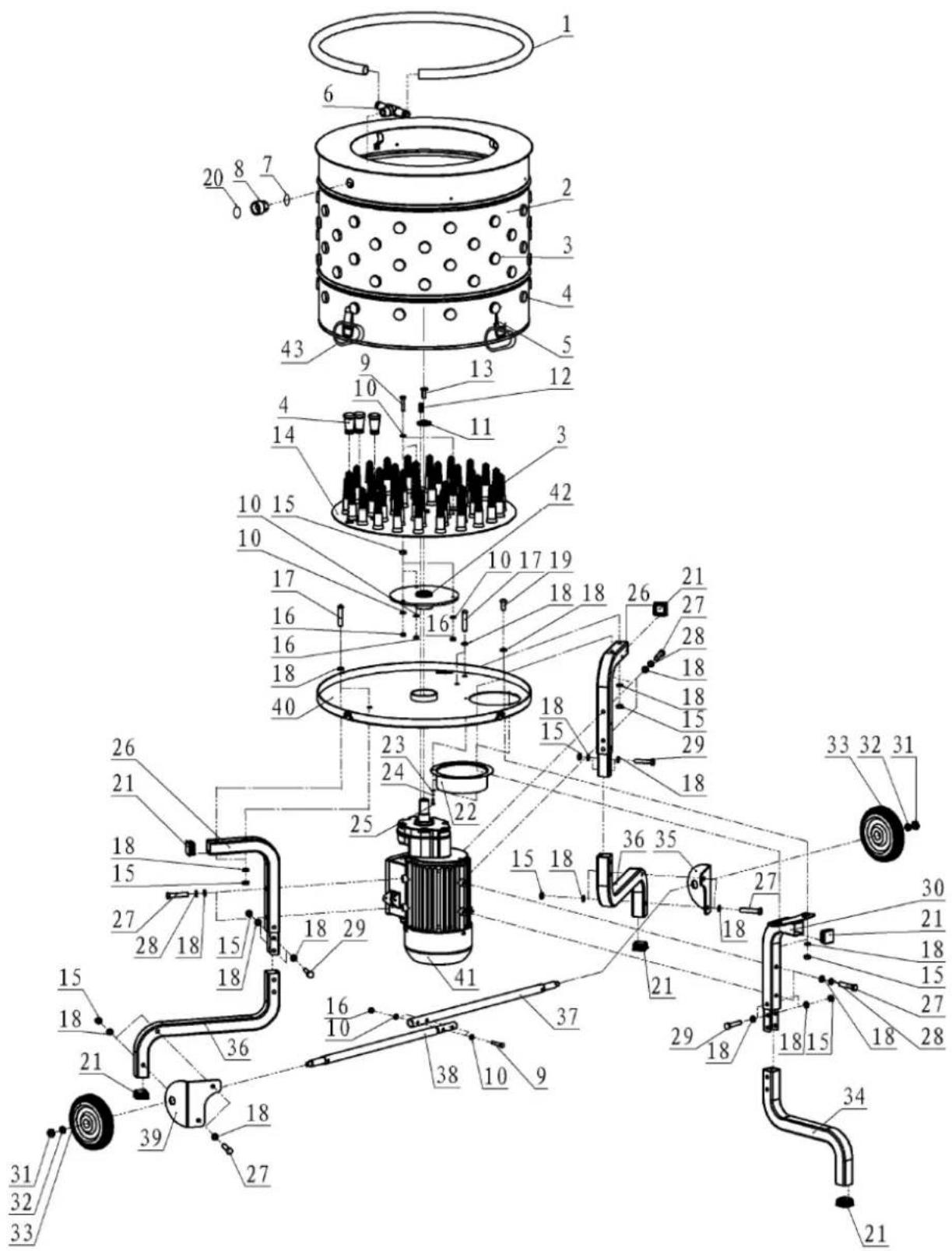
| N° | DESCRIPTION | QTY. |
| 1 | HOSE TUB WATER SPRAYER | 1 |
| 2 | ASSY DRUM W/HOSE CLIPS | 1 |
| 3 | FINGER REPLACEMENT 98 MM | 95 |
| 4 | FINGER REPLACEMENT 46 MM | 13 |
| 5 | BUCKLE CLAMP | 4 |
| 6 | FITTING TEE 3/4 NPT X BARB X BARB | 1 |
| 7 | O-RING 24 X 26 X 3.5 MM | 1 |
| 8 | FITTING 3/4 FNPT X GARDEN HOSE SWIVEL | 1 |
| 9 | BOLT M6 X 1.0 X 30 HEX | 2 |
| 10 | WASHER M6 SPRING LOCK | 10 |
| 11 | WASHER M8 X 30 DOMED | 1 |
| 12 | KEY SQUARE 6 X 6 X 17.4 | 1 |
| 13 | BOLT M8 X 1.25 X 20 HEX LEFT HAND THREAD | 1 |
| 14 | FEATHER PLATE | 1 |
| 15 | NUT M8 NYLOCK | 16 |
| 16 | NUT M6 X 1.0 NYLOCK | 5 |
| 17 | BOLT M8 X 1.25 X 45 PHILIPS | 4 |
| 18 | WASHER M8 X 24 X 2.2 FLAT | 32 |
| 19 | BOLT M8 X 1.25 X 20 PHILIPS | 2 |
| 20 | O-RING 26 X 21 X 3 MM | 1 |
| 21 | PLUG SQUARE TUBE 30 MM | 6 |
| 22 | FEATHER CHUTE | 1 |
| 23 | WASHER M4 FLAT | 3 |
| 24 | WASHER M4 SPRING LOCK | 3 |
| 25 | BOLT M4 X 0.7 X 8 PHILIPS | 3 |
| 26 | AXLE LEG TOP 30 MM | 2 |
| 27 | BOLT M8 X 1.25 X 45 HEX | 8 |
| 28 | WASHER M8 SPRING LOCK | 6 |
| 29 | BOLT M8 X 1.25 X 40 HEX | 3 |
| 30 | SUPPORT LEG TOP 30 MM | 1 |
| 31 | NUT M10 X 1.5 NYLOCK | 2 |
| 32 | WASHER M10 X 20 X 2 FLAT | 2 |
| 33 | WHEEL KIT WITH HARDWARE | 1 |
| 34 | SUPPORT LEG BOTTOM 30 MM | 1 |
| 35 | SUPPORT BRACKET AXLE FEM | 1 |
| 36 | AXLE LEG BOTTOM 30 MM | 2 |
| 37 | ASSY AXLE FEMALE PLUCKER | 1 |
| 38 | ASSY AXLE MALE PLUCKER | 1 |
| 39 | SUPPORT BRACKET AXLE MALE | 1 |
| 40 | FEATHER PAN | 1 |
| 41 | MOTOR ASSEMBLY | 1 |
| 42 | WELDMENT FEATHER PLATE HUB | 1 |
| 43 | CARABINER PLUCKER | 4 |
28.5 Explosionszeichnung / Exploded view / Rastavljeni nacrt GRM1650 / Vue éclatée
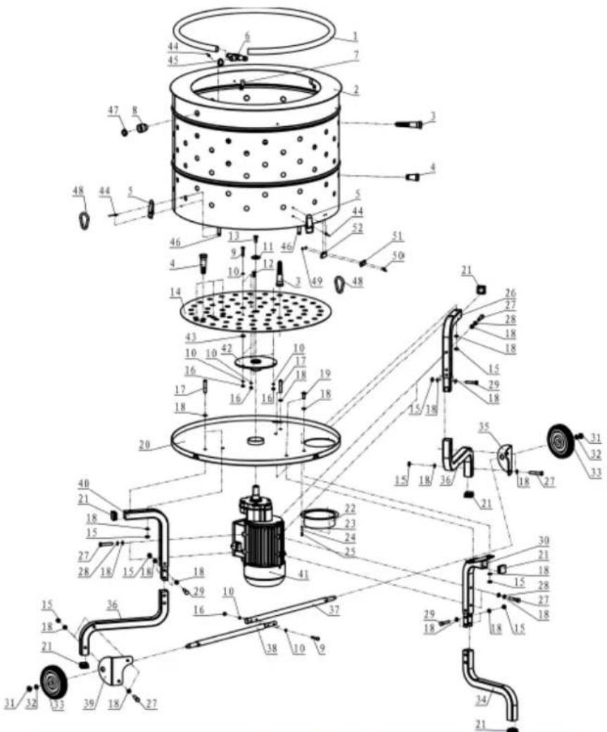
| N° | DESCRIPTION | QTY. | N° | DESCRIPTION | QTY. |
| 1 | Water hose | 1 | 27 | Bolt | 16 |
| 2 | Drum | 1 | 28 | Elastic washer | 6 |
| 3 | Long rubber finger-98mm | 130 | 29 | Bolt | 2 |
| 4 | Short rubber finger-46mm | 28 | 30 | Support leg-middle | 1 |
| 5 | Carabiner | 4 | 31 | Lock nut | 2 |
| 6 | Fitting tee | 1 | 32 | Big washer | 2 |
| 7 | Fixing plate | 5 | 33 | Wheel | 2 |
| 8 | Copper fitting | 1 | 34 | Support leg-bottom | 1 |
| 9 | Bolt | 3 | 35 | Wheel bracket (A) | 1 |
| 10 | Washer | 10 | 36 | Alxe leg-bottom | 2 |
| 11 | Pressing plate | 1 | 37 | Assembly axle-female | 1 |
| 12 | Flat key | 1 | 38 | Assembly axle-male | 1 |
| 13 | Bolt | 1 | 39 | Wheel bracket (B) | 1 |
| 14 | Feather plate | 1 | 40 | Alxe leg-top | 1 |
| 15 | Lock nut | 16 | 41 | Motor | 1 |
| 16 | Lock nut | 5 | 42 | Weldment feather plate | 1 |
| 17 | Bolt | 4 | 43 | Nut | 3 |
| 18 | Big washer | 32 | 44 | Rivet | 13 |
| 19 | Bolt | 2 | 45 | Rubber pad | 1 |
| 20 | Feather pan | 1 | 46 | Insert plate | 4 |
| 21 | Plastic insert | 6 | 47 | Rubber pad | 1 |
| 22 | Feather chute | 1 | 48 | Pin | 4 |
| 23 | Washer | 3 | 49 | Nut | 2 |
| 24 | Elastic washer | 3 | 50 | Screw | 2 |
| 25 | Bolt | 3 | 51 | Safety switch plate | 1 |
| 26 | Alxe leg-upper | 1 | 52 | Safety switch | 1 |
Company ZIPPER Maschinen GmbH grants for mechanical and electrical components a warranty period of 2 years for amateur use; and warranty period of 1 year for professional use, starting with the purchase of the final consumer. In case of defects during this period, which are not excluded by paragraph 3, ZIPPER will repair or replace the machine at its own discretion.
2.) Report:
In order to check the legitimacy of warranty claims, the final consumer must contact his dealer. The dealer has to report in written form the occurred defect to ZIPPER. If the warranty claim is legitimate, ZIPPER will pick up the defective machine from the dealer. Returned shippings by dealers which have not been coordinated with ZIPPER, will not be accepted and refused.
3.) Regulations:
a) Warranty claims will only be accepted, when a copy of the original invoice or cash voucher from the trading partner of ZIPPER is enclosed to the machine. The warranty claim expires if the accessories belonging to the machine are missing.
b) The warranty does not include free checking, maintenance, inspection or service works on the machine. Defects due to incorrect usage of the final consumer or his dealer will not be accepted as warranty claims either. Some examples: usage of wrong fuel, frost damages in water tanks, leaving fuel in the tank during the winter, etc.
c) Defects on wear parts are excluded, e.g. carbon brushes, collection bags, knives, cylinders, cutting blades, clutches, sealings, wheels, saw blades, splitting crosses, riving knives, riving knife extensions, hydraulic oils, oil/air/fuel filters, chains, spark plugs, sliding blocks, etc.
d) Also excluded are damages on the machine caused by incorrect or inappropriate usage, if it was used for a purpose which the machine is not supposed to, ignoring the user manual, force majeure, repairs or technical manipulations by not authorized workshops or by the customer himself, usage of non-original ZIPPER spare parts or accessories.
e) After inspection by our qualified personnel, resulted costs (like freight charges) and expenses for not legitimated warranty claims will be charged to the final customer or dealer.
f) In case of defective machines outside the warranty period, we will only repair after advance payment or dealer's invoice according to the cost estimate (incl. freight costs) of ZIPPER.
g) Warranty claims can only be granted for customers of an authorized ZIPPER dealer who directly purchased the machine from ZIPPER. These claims are not transferable in case of multiple sales of the machine.
4.) Claims for compensation and other liabilities:
The liability of company ZIPPER is limited to the value of goods in all cases. Claims for compensation because of poor performance, lacks, damages or loss of earnings due to defects during the warranty period will not be accepted. ZIPPER insists on its right to subsequent improvement of the machine.
32 JAMSTVO (HR)
1.) Jamstvo:
We monitor our products even after delivery.
In order to guarantee a continuous improvement process, we depend on you and your impressions when handling our products:
- Problems that occur when using the product
- Malfunctions that occur in certain operating situations
- Experiences that can be important for other users
We ask you to note such observations and send them to us by e-mail, fax or post:
Mi svoje proizvode pratimo i nakon isporuke.
Kako bismo mogli zajamčiti stalno poboljšavanje ovisni smo o Vama i Vašim utiscima u rukovanju našim proizvodima:
- Problemi do kojih dolazi tijekom uporabe proizvoda
- Pogreške u radu u specifičnim situacijama
- Iskustva koja bi mogla biti važna za druge korisnike
Molimo Vas da takva opažanja zabilježite te nam ih pošaljete putem e-maila, faksa ili poštom:
Please describe amongst others in the problem: What has cause the problem/defect, what was the last activity before you noticed the problem/defect? For electrical problems: Have you had checked you electric supply and the machine already by a certified electrician?
3. Bitte beachten
/ Additional information
INCOMPLETELY FILLED SERVICE FORMS CANNOT BE PROCESSED! FOR GUARANTEE CLAIMS PLEASE ADD A COPY OF YOUR ORIGINAL SALES / DELIVERY RECEIPT OTHERWISE IT CANNOT BE ACCEPTED. FOR SPARE PART ORDERS PLEASE ADD TO THIS SERVICE FORM A COPY OF THE RESPECTIVE EXPLODED DRAWING WITH THE REQUIRED SPARE PARTS BEING MARKED CLEARLY AND UNMISTAKABLE. THIS HELPS US TO IDENTIFY THE REQUIRED SPARE PARTS FASTLY AND ACCEL- LERATES THE HANDLING OF YOUR INQUIRY.

- INHALT / INDEX
- INHALT / INDEX 2
- ASSEMBLY 22
- OPERATION 27
- MAINTENANCE 27
- TROUBLE SHOOTING 28
- PREDGOVOR (HR) 29
- SIGURNOST 30
- MONTAŽA 32
- RAD 37
- ODRŽAVANJE 38
- UKLANJANJE POGREŠAKA 39
- AVANT-PROPOS (FR) 40
- SECURITE 41
- Please follow the security instructions!
- Copyright law
- Customer Support
- SAFETY
- Intended Use
- Prohibited use:
- Security instructions
- Remaining risk factors
- WARNING
- ASSEMBLY
- Assembly ZI-GRM400
- Assembly ZI-GRM1100 and ZI-GRM1650
- Unpack the machine (FIGURE 1)
- OPERATION
- Operation instructions
- Operation
- MAINTENANCE
- ATTENTION
- NOTICE
- Maintenance plan
- After each workshift:
- Cleaning
- Disposal
- TROUBLE SHOOTING
- PREDGOVOR (HR)
- Poštovani korisniče!
- Cher client, chère cliente,
- ERSATZTEILE / SPARE PARTS / REZERVNI DIJELOVI / PIECES DE RECHANGE
- Ersatzteilbestellung / Spare parts order / Naručivanje rezervnih dijelova / Commande de pièces détachées
- IMP OR TAN T
- The installation of other than original spare parts voids the warranty!
- Explosionszeichnung / Exploded view / Rastavljeni nacrt GRM1100 / Vue éclatée
- Explosionszeichnung / Exploded view / Rastavljeni nacrt GRM1650 / Vue éclatée
- 2.) Report:
- 3.) Regulations:
- 4.) Claims for compensation and other liabilities:
- JAMSTVO (HR)
- 1.) Jamstvo:
- Bitte beachten
- / Additional information
Brand : Zipper
Model : ZIGRM400
Category : Plucker