Nina - Oven Anselmo Cola - Free user manual and instructions
Find the device manual for free Nina Anselmo Cola in PDF.
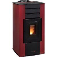
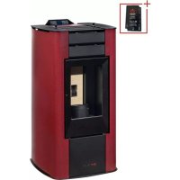
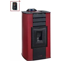
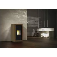
| Product Type | Pellet stove with oven |
| Brand | Anselmo Cola |
| Model | Nina |
| Fuel | Certified wood pellets (DINplus/ENplus A1) (diameter 6±0.5 mm, length 6-30 mm, max humidity 10%) |
| Rated power | 7.5 kW |
| Maximum power | 8.5 kW |
| Power supply | 230 V ~ 50 Hz |
| Efficiency | High (not specified, typically >85%) |
| Hopper capacity | Approximately 20 kg (estimate) |
| Dimensions (L x D x H) | Approximately 100 x 50 x 50 cm (estimate) |
| Weight | Approximately 100 kg (estimate) |
| Main functions | Automatic ignition, 5 power levels (P1-P5), oven mode (OVEN) with temperature probe, weekly/daily programming, optional IR remote control, chronothermostat |
| Safety | Manual reset safety thermostat, anti-explosion device, flue gas temperature probe, pressure switch, flame detection, overheat protection |
| Daily maintenance | Cleaning the brazier and emptying the ash drawer (when cold), cleaning the glass with a damp cloth |
| Periodic maintenance | Annual cleaning of the flue by a professional, scheduled maintenance every year by authorized after-sales service |
| Flue gas evacuation | Diameter 80 mm, max length 6 m, each 90° elbow or T-joint equals 1 m, insulated chimney throughout its length |
| Installation | By a qualified professional, comply with national standards (e.g., UNI 10683 in Italy), minimum distance of 1.5 m in front and 30 cm on sides from combustible materials |
| Warranty | 2 years for individuals, 1 year for professionals (according to applicable legislation) |
Frequently Asked Questions - Nina Anselmo Cola
User questions about Nina Anselmo Cola
0 question about this device. Answer the ones you know or ask your own.
Ask a new question about this device
Download the instructions for your Oven in PDF format for free! Find your manual Nina - Anselmo Cola and take your electronic device back in hand. On this page are published all the documents necessary for the use of your device. Nina by Anselmo Cola.
USER MANUAL Nina Anselmo Cola
MANUEL D'ISTSTRUCTIONS
FRANÇAIS p. 79 - 116
BEDIENUNGSHANDBUCH
MANUAL DE INSTRUÇÕES
PORTUGUÊS p. 193 - 230
INSTRUCTIEHANDLEIDING
NEDERLAND p. 231 - 269
INSTRUKTIONSBOG
DANSK side 270 - 306

natural_image
Blue circular logo with white stylized 'EVA' letters, no additional text or symbolsSTAMPAGGI
MANUALE D'ISTRUZIONI
STUFA A PELLET
INSERTO A PELLET
CUCINA A PELLET
CALDAIA AD ARIA
STUFE ERMETICHE
STUFA A PELLET CON FORNO
CUCINA A PELLET CON FORNO

IMPORTANTE: DA LEGGERE ASSOLUTAMENTE

natural_image
Interior view of a dark room with a metal door and a magnifying glass (no visible text or symbols)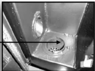
natural_image
Close-up of a metal sink with a circular vent and a circular hole, showing an arrow pointing to the drain (no text or symbols visible)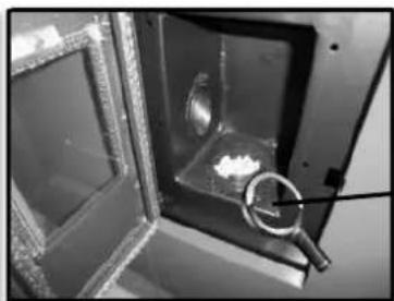
natural_image
Interior view of a mechanical or industrial device with a magnifying glass and internal components (no visible text or symbols)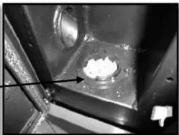
natural_image
Close-up of a mechanical component with a central circular feature and an arrow pointing to it (no visible text or symbols)
natural_image
Black top hat filled with granular material, no visible text or symbols
natural_image
Hand holding a small object with textured surface, possibly food or material (no visible text or symbols)
natural_image
Hand holding a small container filled with granular material (no text or symbols visible)
natural_image
Close-up of a dark mechanical component with white circular holes next to a pile of granular material (no text or symbols visible)
natural_image
Black-and-white photo of a wooden toolbox filled with small objects, no visible text or symbols
natural_image
Hand holding a metal tool with scattered seeds, no visible text or symbols
natural_image
Close-up of a hand holding a tool next to a pile of granular material (no text or symbols visible)
natural_image
Black-and-white photo showing a box with circular patterns next to a pile of dried plant material (no text or symbols visible)
natural_image
Close-up of a mechanical component with a transparent plastic clip and a rectangular housing (no visible text or symbols)
natural_image
Close-up of a hand pressing down on a mechanical component (no visible text or symbols)
natural_image
Close-up of a metal grate with a rectangular block and a perforated tray, next to a dark surface (no visible text or symbols)F-1

text_image
P1 L1 D1 L2 L3 P6 1 SET 23°C OK SET P2 P3 D2 L4 L5 P4 P5F-2
text_image
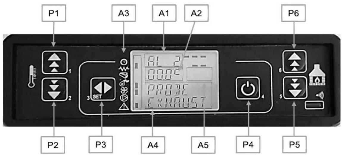
P1 A3 A1 A2 P6 1 2 3 SET 81 2 00.00°C PROJEC EXHRAJUST P2 P3 A4 A5 P4 P5F-3

text_image
B1 B2 AL 2 0.00°C PROJSE EXHAUSTF-4

text_image
P2 L1 L4 L2 D1 L5 L3 P3 L0 P1 -1 + - 20.8°C 3F-5
text_image
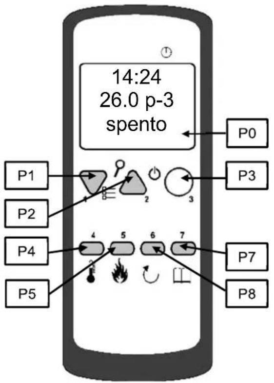
14:24 26.0 p-3 spento P0 P1 P2 P3 P4 P5 4 5 6 7 P7 P8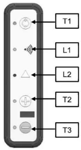
text_image
T1 L1 L2 T2 T3F-6

flowchart
graph TD
    A["LUNEDI '07/03/2016 11:54 18.2°C Spento 12 A NORMALE 34"] --> B["D1"]
    A --> C["D2"]
    A --> D["D3"]
    A --> E["D4"]
    A --> F["D6"]
    A --> G["D7"]
    H["P1"] --> I["Button 1"]
    J["P3"] --> K["Button 2"]
    L["P5"] --> M["Button 3"]
    N["P2"] --> O["Button 4"]
    P["P4"] --> Q["Button 5"]
    R["P6"] --> S["Button 6"]
F-7

flowchart
graph TD
    A["A7-a"] --> B["Processing Unit 1"]
    C["A7-b"] --> D["Processing Unit 2"]
    E["A7-c"] --> F["Processing Unit 3"]
    G["A7-d"] --> H["Processing Unit 4"]
    I["A2"] --> J["Output Module 1"]
    K["A3"] --> L["Output Module 2"]
    M["0 1 2 3 4 5 6 7 8 9 10 11"] --> N["1 LUNEDI"]
    O["12 13 14 15 16 17 18 19 20 21 22 23"] --> P["Output Module 3"]
    Q["A4"] --> R["Output Module 4"]
    S["A5"] --> T["Output Module 5"]
    U["A6"] --> V["Output Module 6"]
-
SICUREZZA DEL PRODOTTO.... pag. 8
-
CANNA FUMARIA.... pag. 9
02.01 COMIGNOLO.... pag. 11
02.02 TIRAGGIO.... pag. 11
02.03 EFFICIENZA STUFA.... pag. 11
natural_image
Technical drawing of a mechanical assembly with cross-hatched sections and central bore (no text or symbols)text_image
MAX A+1/2A Atext_image
Product label of a metallic cylindrical device with printed specifications and brandingtext_image
Cave Pallets Cave Pallets Cave Pallets Cave Palletsnatural_image
Three technical diagrams showing vertical structural connections with arrows and components, no text or symbols present.natural_image
Technical line drawing of a mechanical assembly with no visible text or symbols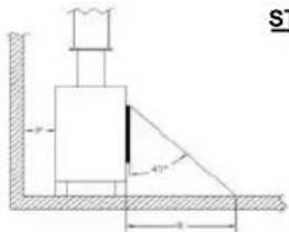
text_image
S7 40°STUFE e CALDAIE
text_image
Technical diagram showing a mechanical or electrical component with labeled parts and directional arrowsINFIAMMABILE
CALDAIA AD ARIA 13,5 KW (15) SPC-15
| PARETE POSTERIORE P = 120 mm |
| PARETE LATERALE L = 300 mm |
| PAVIMENTO F = - mm |
| FRONTE R = 100 mm |
CALDAIA ARIA 18 KW (19,5) SPC-19,5
| PARETE POSTERIORE P = 120 | mm |
| PARETE LATERALE L = 300 | mm |
| PAVIMENTO F = - | mm |
| FRONTE R = 100 | mm |
CALDAIA AD ARIA 18,5 KW (20,5) GP-20
| PARETE POSTERIORE P = 80 | mm |
| PARETE LATERALE L = 200 | mm |
| PAVIMENTO F = - | mm |
| FRONTE R = 100 | mm |
CUCINA A PELLET 6,7 KW (7,5) CPV-7627
STUFA A PELLET 8 KW (9) SPCT8
| PARETE POSTERIORE P = 100 | mm |
| PARETE LATERALE L = 250 | mm |
| PAVIMENTO F = - | mm |
| FRONTE R = 1000 | mm |
STUFA A PELLET 7,5 KW (8,6) SPSV
| PARETE POSTERIORE P = 200 | mm |
| PARETE LATERALE L = 200 | mm |
| PAVIMENTO F = - | mm |
| FRONTE R = 1000 | mm |
STUFA PELLET 6,5 KW (7,5) SPIN7,5AT
| PARETE POSTERIORE P = | 300- mm |
| PARETE LATERALE L = | 150- mm |
| PAVIMENTO F = | 60- mm |
| FRONTE R = 1000 | mm |
STUFA A PELLET 10,5 KW (12) ANGOLO
| PARETE POSTERIORE P = | - mm |
| PARETE LATERALE L = | - mm |
| PAVIMENTO F = - | mm |
| FRONTE R = 1000 | mm |
NON INFIAMMABILE
STUFA ERMETICA SLIM 7 KW (8) SPE7
| PARETE POSTERIORE P = 50 | mm |
| PARETE LATERALE L = 200 | mm |
| PAVIMENTO F = - | mm |
| FRONTE R = 1000 | mm |
STUFA A PELLET 5 KW (6) SP6
| PARETE POSTERIORE P = 250 | mm |
| PARETE LATERALE L = 200 | mm |
| PAVIMENTO F = - | mm |
| FRONTE R = 1000 | mm |
STUFA A PELLET 8 KW (9) SPCT8
| PARETE POSTERIORE P = 100 | mm |
| PARETE LATERALE L = 150 | mm |
| PAVIMENTO F = - | mm |
| FRONTE R = 1000 | mm |
STUFA A PELLET 7,5 KW (8,6) SPSV
| PARETE POSTERIORE P = 150 mm |
| PARETE LATERALE L = 150 mm |
| PAVIMENTO F = - mm |
| FRONTE R = 1000 mm |
STUFA PELLET 6,5 KW (7,5) SPIN7,5AT
| PARETE POSTERIORE P = | 200- mm |
| PARETE LATERALE L = | 100- mm |
| PAVIMENTO F = | 60- mm |
| FRONTE R = 1000 | mm |
STUFA A PELLET 10,5 KW (12) ANGOLO
| PARETE POSTERIORE P = | - mm |
| PARETE LATERALE L = | - mm |
| PAVIMENTO F = - | mm |
| FRONTE R = 1000 | mm |
STUFA ERMETICASLIM 8,5 KW (9,5) SPE8,5
| PARETE POSTERIORE P = 50 | mm |
| PARETE LATERALE L = 150 | mm |
| PAVIMENTO F = - | mm |
| FRONTE R = 1000 | mm |
STUFA A PELLET CAN 14 KW (15) SPV-M13
| PARETE POSTERIORE P = 200 | mm |
| PARETE LATERALE L = 300 | mm |
| PAVIMENTO F = - | mm |
| FRONTE R = 1000 | mm |
STUFA PELLET con FORNO 7,5 KW (8,5) SPF8.5
| PARETE POSTERIORE P = 200 | mm |
| PARETE LATERALE L = 300 | mm |
| PAVIMENTO F = - | mm |
| FRONTE R = 1000 | mm |
STUFA A PELLET SLIM 4 KW (5,5) SP4
| PARETE POSTERIORE P = 40 | mm |
| PARETE LATERALE L = 300 | mm |
| PAVIMENTO F = - | mm |
| FRONTE R = 1000 | mm |
STUFA A PELLET CAN 7,5 KW (9) SPCA7,5
| PARETE POSTERIORE P = 250 | mm |
| PARETE LATERALE L = 250 | mm |
| PAVIMENTO F = - | mm |
| FRONTE R = 1000 | mm |
STUFA A PELLET SLIM 4 KW (5,5) SP4
| PARETE POSTERIORE P = 40 | mm |
| PARETE LATERALE L = 300 | mm |
| PAVIMENTO F = - | mm |
| FRONTE R = 1000 | mm |
STUFA ERMETICA SLIM 8,5 KW (9,5) SPE8,5
| PARETE POSTERIORE P = 50 | mm |
| PARETE LATERALE L = 50 | mm |
| PAVIMENTO F = - | mm |
| FRONTE R = 1000 | mm |
STUFA A PELLET CAN 14 KW (15) SPV-M13
| PARETE POSTERIORE P = 200 | mm |
| PARETE LATERALE L = 200 | mm |
| PAVIMENTO F = - | mm |
| FRONTE R = 1000 | mm |
STUFA PELLET con FORNO 7,5 KW (8,5) SPF8.5
| PARETE POSTERIORE P = 200 | mm |
| PARETE LATERALE L = 200 | mm |
| PAVIMENTO F = - | mm |
| FRONTE R = 1000 | mm |
STUFA A PELLET SLIM 4 KW (5,5) SP4
| PARETE POSTERIORE P = 40 | mm |
| PARETE LATERALE L = 200 | mm |
| PAVIMENTO F = - | mm |
| FRONTE R = 1000 | mm |
STUFA A PELLET CAN 7,5 KW (9) SPCA7,5
| PARETE POSTERIORE P = 200 | mm |
| PARETE LATERALE L = 200 | mm |
| PAVIMENTO F = - | mm |
| FRONTE R = 1000 | mm |
STUFA A PELLET SLIM 4 KW (5,5) SP4
| PARETE POSTERIORE P = 40 | mm |
| PARETE LATERALE L = 200 | mm |
| PAVIMENTO F = - | mm |
| FRONTE R = 1000 | mm |
STUFA A PELLET 11,5 KW (13,5) SPV-M11S
| PARETE POSTERIORE P = 200 | mm |
| PARETE LATERALE L = 300 | mm |
| PAVIMENTO F = - | mm |
| FRONTE R = 1000 | mm |
STUFA PELLET SLIM CAN 9,3 KW (10,5) SPCS9
| PARETE POSTERIORE P = 50 | mm |
| PARETE LATERALE L = 200 | mm |
| PAVIMENTO F = - | mm |
| FRONTE R = 1000 | mm |
text_image
Technical drawing showing two cross-sectional views of a mechanical component with dimension labels A, B, C and hatching patterns.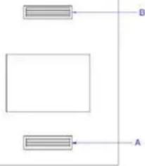
flowchart
graph TD
    A["Process Block A"] --> B["Process Block B"]
    B --> C["End"]
solo STUFA ERMETICA
SOLO STUFE AD ANGOLO
text_image
USCITA ARIA VENTILAPIASTRA IN ACCIAIO O VETRO
text_image
RS 232 TERMOSTATO DI SICUREZZAINTERRUTTORE ON/OFF
natural_image
Close-up of electrical components with wires and a small electronic device (no visible text or symbols)INTERRUTTORE ON/OFF
MORSETTI SONDE AMBIENTE
O TERMOSTATI
RICEVITORE RADIOCOMANDO
INTERRUTTORE DI EMERGENZA
COPERCHIO PELLET
GUARNIZIONE COPERCHIO
TERMOSTATO DI SICUREZZA
natural_image
Close-up of a small electronic device with a mounted sensor or sensor array, no visible text or symbols
natural_image
Exterior view of a white electronic device with a display and control panel (no visible text or symbols)text_image
1 2 3 4 A#C
natural_image
Close-up of a mechanical component with cylindrical and rectangular parts, no visible text or symbolsUT05 --- I" ACCENSIONE (es. ore 07,00)
UT06 --- I° SPEGNIMENTO (es. ore 09,00)
UT07 --- CONFERMA GIORNI (es. DAY 1-OFF / DAY2-OFF/DAY3-OFF/DAY4-OFF/DAY5-OFF/DAY6-ON/DAY7-ON)
PROGRAMMA 2
UT08 --- II" ACCENSIONE (es. ore 18,00)
UT09 --- II° SPEGNIMENTO (es. ore 24,00)
UT10 --- CONFERMA GIORNI (es. DAY 1-ON / DAY2-ON/DAY3-ON/DAY4-ON/DAY5-ON/DAY6-OFF/DAY7-OFF)
CANALIZZAZIONE
text_image
Close-up of a device panel with warning label and warning symbol in ChinesePulsante (P4) ON/OFF
Led (L2) Coclea in movimento – COCLEA ON
natural_image
Black rectangular electronic device with four buttons (no visible text or symbols)natural_image
Close-up of a hand using a tool to clean or store items on a dark surface, no visible text or symbolsSOLO PER CUCINA A PELLET
text_image
T1 L1 L2 T2 T3F-6

flowchart
graph TD
    A["D1"] --> B["LUNEDI' 07/03/2016 11:54, 18.2°C Spento 12 A NORMALE 34"]
    C["D2"] --> B
    D["D3"] --> B
    E["D4"] --> B
    F["D5"] --> B
    G["D6"] --> B
    H["D7"] --> B
    I["P1"] --> J["Image with question mark"]
    K["P3"] --> L["Image with + symbol"]
    M["P5"] --> N["Image with minus symbol"]
    O["P2"] --> P["Image with power icon"]
    Q["P4"] --> R["Image with document icon"]
    S["P6"] --> T["Image with triangle symbol"]
F-7

flowchart
graph TD
    A["A7-a"] --> B["A7-b"]
    B --> C["A7-c"]
    C --> D["A7-d"]
    D --> E["1 LUNEDI"]
    E --> F["A2"]
    E --> G["A3"]
    F --> H["0 1 2 3 4 5 6 7 8 9 10 11"]
    G --> I["12 13 14 15 16 17 18 19 20 21 22 23"]
    I --> J["..."]
    K["A1"] --> L["A4"]
    M["A7"] --> N["A5"]
    O["A6"] --> P["A6"]

IMPORTANT: READ THE FOLLOWING INFORMATION

-
The warranty is valid in the presence of a certified installation by AUTHORIZED PERSONNEL.
-
DO NOT TURN THE PRODUCT UPSIDE DOWN or LAY IT IN A HORIZONTAL POSITION during transportation and installation.
-
Stove installation must be carried out by qualified staff and pursuant to the regulations in force in the relevant country.
-
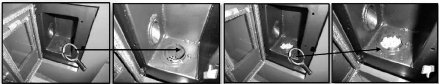
EMPTY THE BURN POT before trying to switch the stove back on in case of ignition failure or power outage. Failure to do so may also result in the breaking of the door glass.
-
DO NOT POUR PELLETS BY HAND in the burn pot to facilitate stove's ignition.
-
Should any anomaly concerning the flame be detected or, however, in any other case, NEVER SWITCH OFF the stove by disconnecting it from the mains. Use the relevant button. Disconnecting the stove from the mains will prevent exhaust fumes from being extracted.
-
Should ignition phase take longer than expected (due to damp or poor quality pellets) generating excessive smoke in the combustion chamber, open the door to expel it, while remaining in a position that guarantees your safety.
-
It is highly important to use GOOD QUALITY CERTIFIED PELLETS. The manufacturer declines any liability for any malfunctioning or damage to mechanical parts due to the use of poor quality pellets.
-
The burn pot and the combustion chamber MUST BE CLEANED DAILY. The manufacturer declines any liability for any malfunctioning due to a failure to do so.
Eva Stampaggi S.r.l. declines any liability for any damage to persons or property arising from the failure to comply with the points mentioned above and from non-compliant product installation.
natural_image
Sequence of five black-and-white photos showing a metal component being inserted into a square opening, with arrows indicating the process (no text or symbols present)
natural_image
Black top hat filled with small white granular material (no text or symbols visible)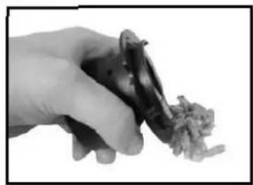
natural_image
Hand holding a small object with granular texture, possibly food or material (no visible text or symbols)
natural_image
Hand holding a small container with scattered granular material (no text or symbols visible)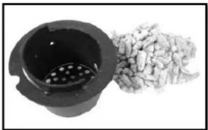
natural_image
Close-up of a black plastic container with white perforated side, next to a pile of small granular material (no text or symbols visible)
natural_image
Black-and-white photo of a wooden toolbox containing small cylindrical objects (no text or symbols visible)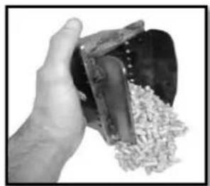
natural_image
Hand holding a metal tool with scattered debris, no visible text or symbols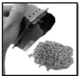
natural_image
Hand pouring granular material into a pile of small granular material (no text or symbols visible)
natural_image
Black-and-white photo of a traditional-style box with circular indentations and a pile of dried herbs (no text or symbols visible)
natural_image
Close-up of a mechanical component with a plastic bag attached to a housing (no visible text or symbols)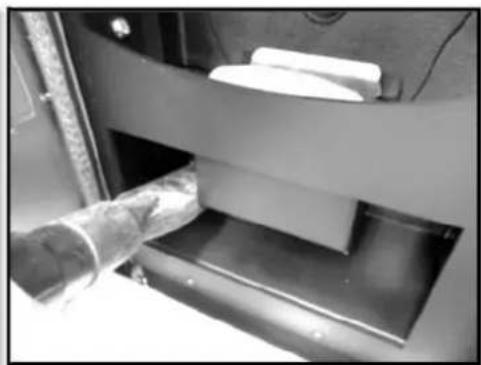
natural_image
Close-up of a hand pressing down on a mechanical component (no visible text or symbols)
natural_image
Close-up of a metallic object with textured surface next to a perforated base (no visible text or symbols)TABLE OF CONTENTS
-
PRODUCT SAFETY p. 46
-
VENT PIPE ...... p. 47
02.01 CHIMNEY COWL p. 49
02.02 DRAUGHT.... p. 49
02.03 STOVE EFFICIENCY p. 49
-
WARNINGS INSTALLATION p. 50
-
INSTALLATION...... p. 52
04.01 PELLET STOVES...... p. 52
04.02 PELLET STÖVES with ÖVEN p. 53
04.03 PELLET INSERTS p. 53
04.04 PELLET KITCHEN.... p. 54
04.05 PELLET KITCHEN with OVEN.... p. 54
04.06 AIR STOVE p. 55
04.07 AIR-TIGHT STOVES p. 55
- PRODCT USE p. 56
05.01 ELECTRONICS WITH 6 BUTTON LED DISPLAY.... p. 56 p. 42 F-1 (Pellet inserts – Canalized pellet stove)
05.02 ELECTRONICS WITH 6 BUTTON LCD DISPLAY.... p. 58 p. 42 F-2 F-3 (Pellet stoves)
05.03 ELECTRONICS WITH 3 BUTTON LED DISPLAY N. 100.... p. 60 p. 42 F-4
(Pellet stoves – Pellet stove with oven – Pellet kitchen – Pellet kitchen with oven)
05.04 ELECTRONICS WITH 6 BUTTON LED DISPLAY N. 100.... p. 62 p. 42 F-1
(Pellet stoves – Pellet inserts)
05.05 ELECTRONICS WITH REMOTE CONTROL (Pellet stoves) p. 64 p. 43 F-5
05.06 ELECTRONICS WITH REMOTE CONTROL LCD.... p. 66 p. 43 F-6
(Air-tight stoves)
05.07 ELECTRONICS WITH REMOTE CONTROL LCD (Air stove) p. 69 p. 43 F-6
05.08 IR REMOTE CONTROL (OPTIONAL).... p. 71
(Pellets stoves - Pellet stove with oven – Pellet kitchen – Pellet kitchen with oven – Pellet inserts)
- CLEANING AND MAINTENANCE p. 72
- TROUBLESHOOTING...... p. 72
- YEARLY SCHEDULED MAINTENANCE ...... p. 74
- CERTIFICATE OF INSTALLATION AND TESTING p. 75-76
- WARRANTY CERTIFICATE ...... p. 78
SAFETY WARNINGS
The stoves were built in compliance according to standard EN13240 (wood stoves), EN 14785 (pellet stoves) and EN 12815 (kitchens and wood-burning stoves) using high quality and non-polluting materials. To make better use of your stove it is advisable to follow the instructions in this booklet.
Read this manual carefully before use or any maintenance operation.
Eva Stampaggi aims to provide as much information as possible to ensure safer use and to avoid damage to persons, property or parts of the stove itself.
Each stove is subjected to internal testing before shipment and as such residues inside the appliance may be found.
RETAIN THIS MANUAL FOR FUTURE REFERENCE.
FOR ANY REQUIREMENT OR CLARIFICATION PLEASE CONTACT
THE AUTHORISED RETAILER
- Installation and connection must be carried out by qualified staff in compliance with local regulations, national and European standards (UNI 10683) and with the annexed installation instructions. Furthermore, these operations must be performed by personnel who are authorised and professionally trained for the task in question.
- The combustion of waste, especially of plastic materials, damages the stove and the vent pipe. Moreover, it is forbidden by the law against the emission of harmful substances.
- Do not use alcohol, petrol or other highly inflammable liquids to light the fire or poke it during operation.
- Do not introduce into the stove an amount of fuel greater than that recommended in this booklet.
- Do not modify the product.
- It is forbidden to use the appliance with the door open or the glass broken.
- Do not use the appliance as, for example, a clothes drying rack, a bearing surface or step etc.
- Do not install the stove in bedrooms or bathrooms if not certified as watertight.
The pellets to be used are the following:
The pellet stoves operate exclusively with pellets made from various types of legislative-compliant wood.
DIN plus or EN plus 14961-2 A1 or PEFC/04-31-0220 or ONORM M7135 or having the following characteristics:
Min calorific value 4.8 kWh/kg (4180 kcal/kg)
Density 630-700 kg/m3
Maximum humidity 10% of the weight
Diameter: 6 ±0.5 mm
Percentage ash: max 1% of the weight
Length: min 6 mm- max 30 mm
Composition: 100% untreated wood from the industry of wood or post-consumption without the addition of binders, bark-free and compliant with current regulations.
GENERAL SAFETY PRECAUTIONS
• Use the stove only as described in this manual. Any other use not recommended by the manufacturer may cause fires or accidents to people.
• Make sure that the electrical power available corresponds to the value indicated on the data plate (220V\~/50Hz).
• This appliance is not a toy. Make sure children are not left unattended and do not use the appliance as a toy.
- This device is not intended for use by persons (including children) with reduced physical or mental capacity, or without specific experience and knowledge, unless supervised or duly instructed on the use of the appliance by a person responsible for their safety.
- Disconnect the appliance from the mains when not in use or during cleaning operations.
• To do so, turn the switch to the O position and disconnect the plug from the socket. Pull the plug, not the cable.
- Never block the combustion air inlets and fume outlets.
- Since the stove is fitted with electrical components, do no touch it with wet hands.
- Do not use the appliance in case of damaged cables or plugs. The device is classified as type Y: the power supply cable may only be replaced by a qualified technician. Should the power supply cable be damaged, it can be replaced only by the manufacturer or by its technical assistance service or by a similarly qualified person.
- Do not place any object on the cable and do not bend it.
- Avoid using extension cables as their temperature may increase excessively posing fire hazards. Never use one single extension cable to power several appliances.
- During normal functioning some parts of the stove may become extremely hot, such as the door, the glass or the handle. Be careful, especially with children. Do not touch any hot parts if not wearing adequate protective devices.
- ATTENTION! DO NOT TOUCH the FIRE DOOR, the GLASS, the HANDLE or the FUME OUTLET DURING FUNCTIONING if not wearing adequate protective devices since they become extremely hot.
- Keep inflammable materials, such as furniture, cushions, pillows, blankets, paper, clothing, curtains, etc., at least 1,5 m away from the stove front and 30 cm from the stove sides and back.
- The stove that is covered by or in direct contact with inflammable materials, including curtains, blankets, etc., during normal operation may result in a fire hazard. KEEP THE APPLIANCE AWAY FROM THE MATERIALS MENTIONED ABOVE.
- Do not immerse the cable, plug or any other appliance component in water or other liquids.
- Do not use the stove in dusty environments or wherever inflammable vapours are generated (e.g. in a workshop or garage).
- The stove is fitted with components that generate arcs and sparks. Do not install the stove in areas posing a significant fire or explosion hazard due to a high chemical substance concentration or to a high humidity level.
- Do not use the appliance close to bathtubs, showers, basins, sinks or swimming pools.
- Do not install the appliance underneath an air vent. Do not install the stove outdoors.
- Do not repair, disassemble or modify the appliance. The appliance is not fitted with components that can be repaired by users.
• Turn off the stove, disconnect it from the mains and wait until it has cooled down completely before performing any maintenance operations.
• WARNING: DISCONNECT THE STOVE FROM THE MAINS BEFORE PERFORMING MAINTENANCE OPERATIONS.
- ATTENTION! These stoves operate exclusively on pellets and possibly also pits if the stove has this option; DO NOT USE OTHER FUELS: any other material that may be burnt will result in failure and malfunction of the appliance.
- Keep the pellets in a fresh dry place: storing pellets in a place that is damp or excessively cold may reduce the stove potential heat output. Be careful when storing and handling pellet bags to prevent pellet crushing and consequent sawdust production.
- The fuel consists of small cylinders with 6-7mm diameter and a maximum length of 30mm. Their maximum moisture content is equal to 8%. This stove is designed to burn pellets made of compacted sawdust obtained from different types of wood, in compliance with environment protection legislation.
- The use of different types of pellets may result in a slight, sometimes even undetectable, change in the stove efficiency. This change can be counterbalanced by increasing or decreasing the stove heat output by only one step.
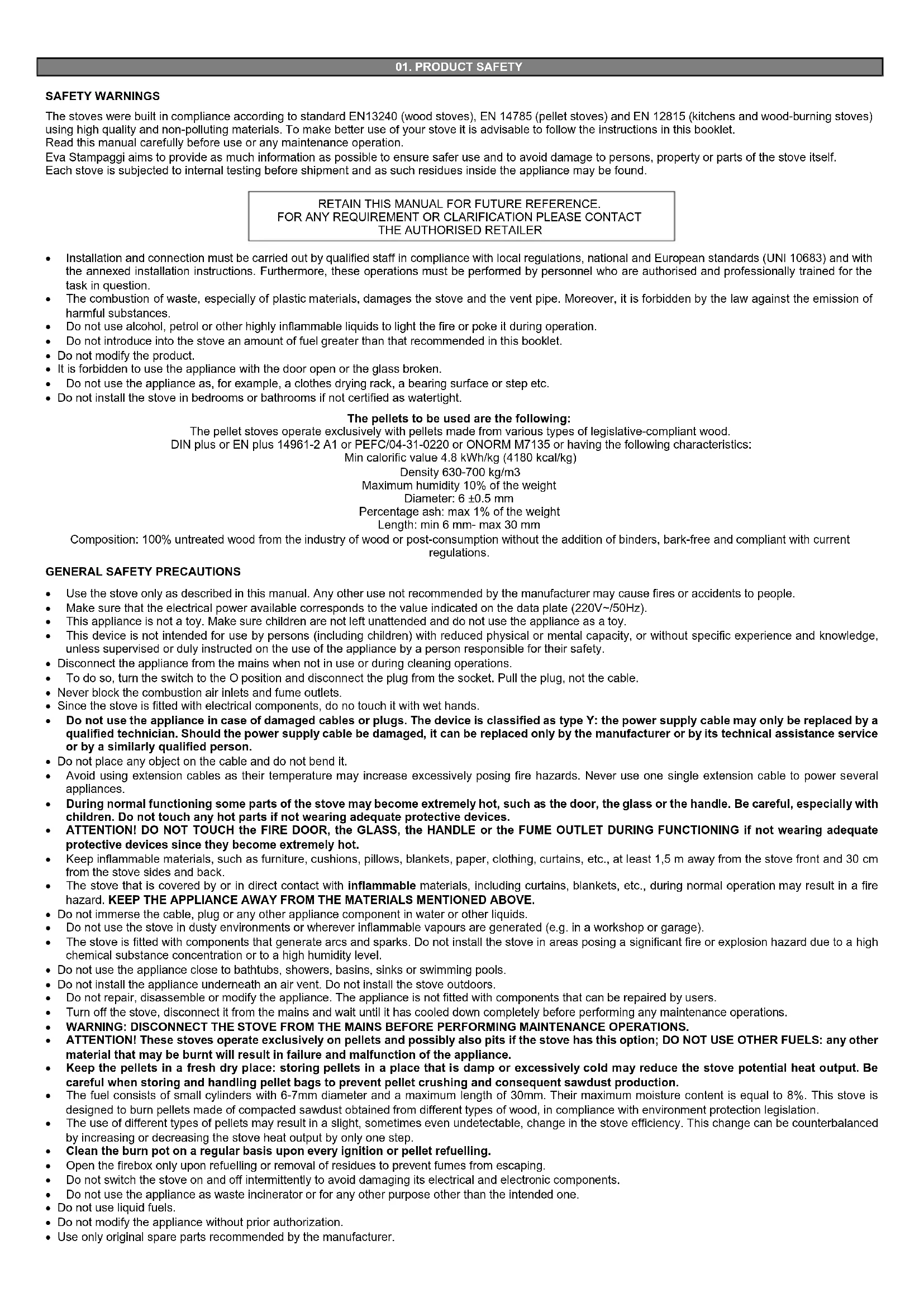
- Clean the burn pot on a regular basis upon every ignition or pellet refuelling.
- Open the firebox only upon refuelling or removal of residues to prevent fumes from escaping.
- Do not switch the stove on and off intermittently to avoid damaging its electrical and electronic components.
- Do not use the appliance as waste incinerator or for any other purpose other than the intended one.
- Do not use liquid fuels.
- Do not modify the appliance without prior authorization.
- Use only original spare parts recommended by the manufacturer.
- Make sure that the stove is transported in compliance with safety regulations.
Avoid any improper transfers or knocks that may damage the ceramics or the structure.
- The metal structure is coated using high temperature paints. When using the appliance for the first few times, unpleasant odours may be given off due to the paint of the metal parts that is drying: this is in no way dangerous and in such case, simply ventilate the premises. After the first heating cycles, the paint will reach its maximum adhesion and all its chemical and physical features.
- The reload the hopper, simply open the access lid and pour in the pellets, also during normal operation, making sure that no pellets fall out of it. Always refuel the hopper before leaving the operating stove unattended for long periods of time.
- Whenever the hopper and the auger tube become completely empty, the appliance will be automatically switched off. It may take two separate ignitions to resume operation at ideal working conditions as the auger tube is very long.
- ATTENTION! If the stove is not properly installed, power outages may result in fume spillages. Under specific circumstances, an uninterrupted power supply unit must be installed.
- ATTENTION! Being a heating appliance, some parts of the stove can become extremely hot. We therefore recommend paying special attention during operation.
WHEN THE STOVE IS WORKING:
- do not open the door;
- do not touch the door glass since it becomes extremely hot;
- keep children away from it;
- do not touch the fume outlet;
- do not pour any liquid inside the firebox;
- do not perform any maintenance operations if the stove is not cold;
- only qualified technicians are allowed to perform any operation;
- follow all the instructions contained herein.
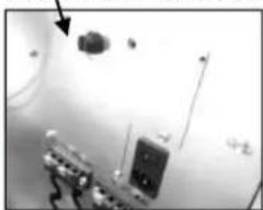
Anti-explosion
Some products are fitted with a safety device to prevent explosion. Before switching on the product or, in any case, after any cleaning operation, make sure that the device is correctly positioned in its seat. The device is located on the firebox door upper edge.
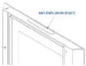
text_image
ANTI-EXPLOSION DEVICEINTRODUCTION
INSTALLATION WITH WALL FUME OUTLET IS PROHIBITED. INSTEAD THE FUME OUTLET MUST BE ROOF-TYPE AS PROVIDED FOR BY NATIONAL REGULATIONS.
Eva Stampaggi S.r.l. declines any liability for any damage to persons or property arising from the failure to comply with the points mentioned above and from non-compliant product installation.
Install the stove according to the regulations in force in the country of use.
For example, in Italy this refers to UNI 10683: 2012, which dictates 4 points
- preliminary activities - for which the retailer/installer is responsible and liable for at the time of the inspection before definitive installation. The preliminary activities include:
• installation site suitability verification;
- fume evacuation system suitability verification;
• external air inlet suitability verification;
At this stage, it is necessary to check that the product can be safely operated and that it satisfies the relevant technical characteristics.
The safety conditions must be ascertained by means of a prior inspection.
Stoves and fireplaces are heating systems and must be installed safely and comply with the manufacturer's instructions!
- Installation - responsibility of the installer. At this phase, the aspects of installation of the product and of the fume evacuation system are taken into account and the following issues are addressed:
• safety distance from combustible materials;
• chimney flue construction, smoke ducts, intubated systems and chimney cowls.
- issuing of additional documents - responsibility of the installer.
Issuing of the technical documentation must include:
- manual of use and maintenance of the appliance and of the components of the system (e.g. smoke ducts, chimney flue, etc.);
- Photocopy or photograph of the chimney flue plate;
-
system manual: (if applicable);
• Declaration of Conformity in relation to Ministerial Decree 37/08. -
control and maintenance - responsibility of the maintenance technician who must oversee protection and maintenance of the product during its operation over time. The operator in charge of control and maintenance of the systems for winter and summer climate control performs these activities to a professional standard in accordance with the regulations in force. The operator, at the end of these operations, must draw up and sign a technical inspection report in accordance with the models provided by the provisions of this decree and the implementing rules, in relation to the type and capacity of the system, to be issued to the person who signs a copy thereby confirming receipt and reading thereof."
02. VENT PIPE
THE PRODUCTION OF THE STOVES IS REQUIRED WITH HIGHER PERFORMANCES, SO IT IS IMPORTANT TO PERFORM THE INSTALLATIONS ACCORDING TO THE LAW. IF THE FLUE DUCT PASSES THROUGH NON-HEATED AREAS, IT MUST BE INSULATED FOR A PROPER COMBUSTION.
STOVE CHARACTERISTICS FOR SIZING OF THE VENT PIPE
| PELLET INSERTS 6,5 KW (7,5) IPGN | |
| Chimney flue draught 12 | Pa |
| Fume temperature 195 | °C |
| Mass flow of fumes 5,6 | g/s |
| PELLET INSERTS 9,5 KW (11) IP9,5 | |
| Chimney flue draught 12 | Pa |
| Fume temperature 173 | °C |
| Mass flow of fumes 8,3 | g/s |
| PELLET KITCHEN 6,7 KW (7,5) CPV-7627 | |
| Chimney flue draught 11 | Pa |
| Fume temperature 164 | °C |
| Mass flow of fumes 5,0 | g/s |
| PELLET STOVES 5 KW (6) SP6 | |
| Chimney flue draught 11 | Pa |
| Fume temperature 227 | °C |
| Mass flow of fumes 4,1 | g/s |
| PELLET STOVES 8 KW (9) SPCT8 | |
| Chimney flue draught 12 | Pa |
| Fume temperature 214 | °C |
| Mass flow of fumes 6,1 | g/s |
| PELLET STOVES 6,5 KW (7,5) SPIN7,5AT | |
| Chimney flue draught 11 | Pa |
| Fume temperature 223 | °C |
| Mass flow of fumes 5,3 | g/s |
| PELLET STOVES with OVEN 7,5 KW (8,5) SPF8,5 | |
| Chimney flue draught 12 | Pa |
| Fume temperature 204 | °C |
| Mass flow of fumes 5,9 | g/s |
| PELLET STOVES SLIM 4 KW (5,5) SP4 | |
| Chimney flue draught 10 | Pa |
| Fume temperature 155 | °C |
| Mass flow of fumes 4,1 | g/s |
| PELLET STOVES SLIM 9 KW (11) SPVM-9 | |
| Chimney flue draught 10 | Pa |
| Fume temperature 217 | °C |
| Mass flow of fumes 7,1 | g/s |
| PELLET KITCHEN with OVEN 8,6 KW (9,3) CPF-85 | |
| Chimney flue draught 12 | Pa |
| Fume temperature 111 | °C |
| Mass flow of fumes 6,1 | g/s |
| PELLET STOVES DUCT. 14 KW (15) SPV-M13 | |
| Chimney flue draught 10 | Pa |
| Fume temperature 244 | °C |
| Mass flow of fumes 8,7 | g/s |
| PELLET STOVES 11,5 KW (13,5) SPV-M11S | |
| Chimney flue draught 11 | Pa |
| Fume temperature 207 | °C |
| Mass flow of fumes 9 | g/s |
| AIR STOVE 13,5 KW (15) SPC-15 | |
| Chimney flue draught 11 | Pa |
| Fume temperature 155 | °C |
| Mass flow of fumes 8,3 | g/s |
| PELLET STOVES DUCT. 7,5 KW (9) SPCA7,5 | |
| Chimney flue draught 10 | Pa |
| Fume temperature 217 | °C |
| Mass flow of fumes 7,4 | g/s |
| PELLET STOVES DUCT. 8 KW (9,3) SPSC8C | |
| Chimney flue draught 11 | Pa |
| Fume temperature 182 | °C |
| Mass flow of fumes 6,1 | g/s |
| PELLET STOVES 10 KW (11,5) SPV-M10 | |
| Chimney flue draught 11 | Pa |
| Fume temperature 226 | °C |
| Mass flow of fumes 6,9 | g/s |
| PELLET STOVES 10,5 KW (12) ANGLE | |
| Chimney flue draught 11 | Pa |
| Fume temperature 204 | °C |
| Mass flow of fumes 7,8 | g/s |
| PELLET STOVES SLIM DUCT. 9,3 KW(10.5) SPCS9 | |
| Chimney flue draught 12 | Pa |
| Fume temperature 206 | °C |
| Mass flow of fumes 5,5 | g/s |
| AIR STOVE 18 KW (19,5) SPC-19,5 | |
| Chimney flue draught 11 | Pa |
| Fume temperature 191 | °C |
| Mass flow of fumes 8,9 | g/s |
| SEALED STOVE 6,5 KW (7,5) SPE6,5 | |
| Chimney flue draught 10 | Pa |
| Fume temperature 195 | °C |
| Mass flow of fumes 5,4 | g/s |
| PELLET STOVES DUCT. 8 KW (9,3) SPSC8 | |
| Chimney flue draught 12 | Pa |
| Fume temperature 185 | °C |
| Mass flow of fumes 5,8 | g/s |
| PELLET STOVES SLIM 6,5 KW (7,5) | |
| Chimney flue draught 11 | Pa |
| Fume temperature 184 | °C |
| Mass flow of fumes 6,2 | g/s |
| AIR-TIGHT STOVES 8,5 KW (9,5) SPE8,5 | |
| Chimney flue draught 12 | Pa |
| Fume temperature 193 | °C |
| Mass flow of fumes 4,8 | g/s |
| AIR-TIGHT STOVES SLIM 7 KW (8) SPE7 | |
| Chimney flue draught 11 | Pa |
| Fume temperature 179 | °C |
| Mass flow of fumes 5,1 | g/s |
| AIR STOVE 18,5 KW (20,5) GP-20 | |
| Chimney flue draught 12 | Pa |
| Fume temperature 161 | °C |
| Mass flow of fumes 12,0 | g/s |
| PELLET STOVES 7,5 KW (8,6) SPSV | |
| Chimney flue draught 10 | Pa |
| Fume temperature | 193 °C |
| Mass flow of fumes 5,6 | g/s |
The vent pipe is one of the key features for guaranteeing the proper functioning of the stove. Thanks to the quality of the materials, the strength, the durability, the easy cleaning and maintenance, the best vent pipes are made of steel, either stainless steel or aluminized.
- The stove is fitted with a 80mm rear round fume outlet and a joint connection to be connected to the vent pipe.
- Use telescopic joint connections to facilitate connection to the steel rigid vent pipe and counterbalance the thermal expansion of both the firebox and the vent pipe.
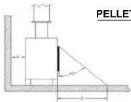
- Seal the vent pipe joint connection with high temperature silicone sealant (1,000°C). Should the existing flue opening not be perfectly perpendicular to the firebox fume outlet, use an elbow to connect them. Inclination must never exceed 45°, with respect to the vertical axis. No constrictions.
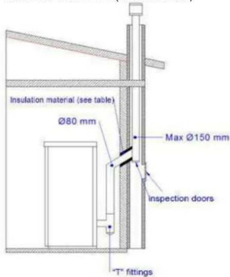
• Use 10cm-thick insulating thimbles if pipe vent passes through floors. - The vent pipe must be insulated along its entire length. Thanks to the vent pipe insulation fume temperature will remain high optimising draught, preventing condensation and reducing build-up of barely ignited particles along the vent pipe walls. Use proper insulating materials (glass wool, ceramic fibre, Class A1 non-combustible materials).
• The vent pipe must be weather-proof and as linear as possible. - Flexible and length-adjustable metal pipes may not be used.
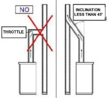
text_image
NO THROTTLE INCLINATION LESS THAN 45°EXISTING VENT PIPE (TRADITIONAL)
text_image
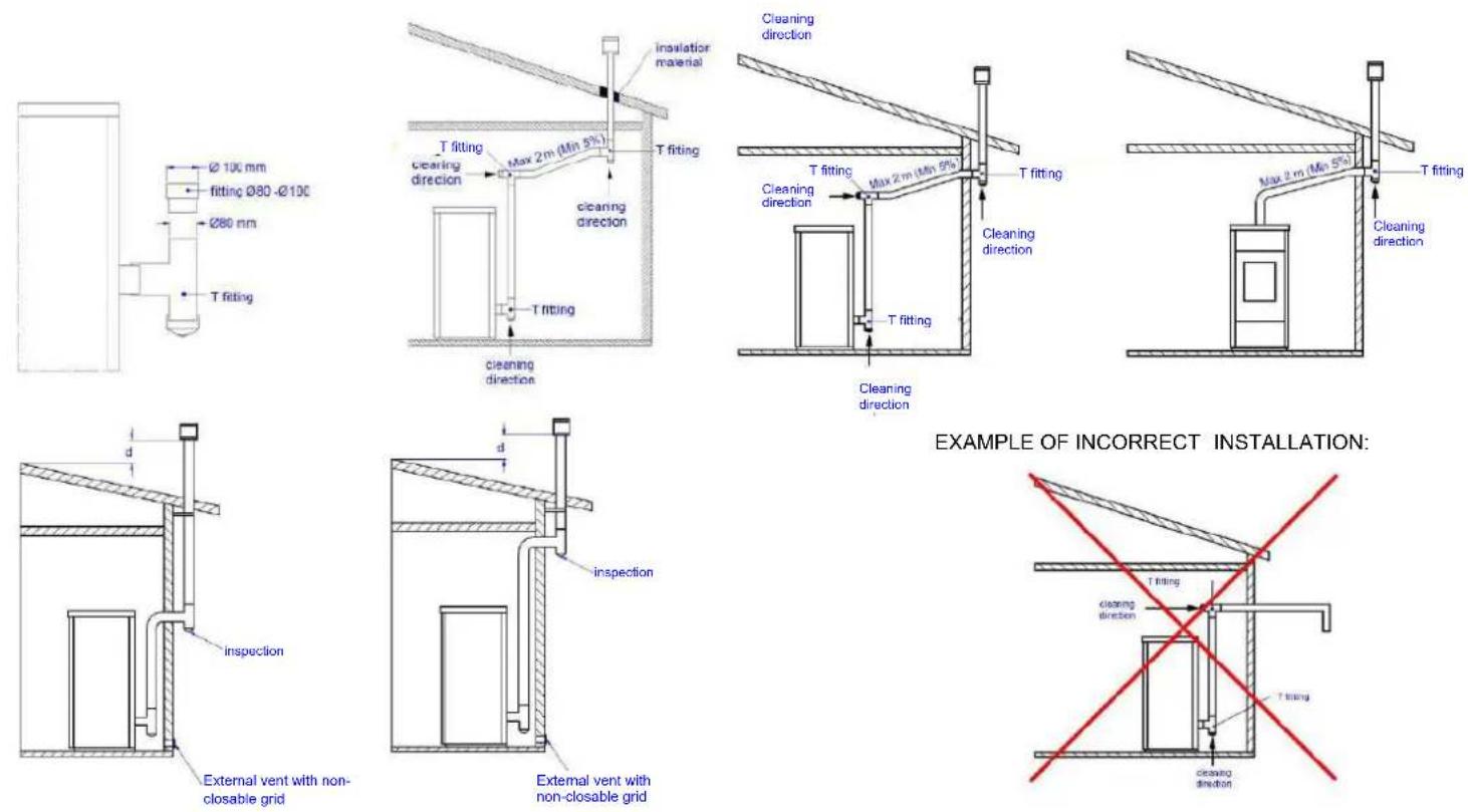
Insulation material (see table) Ø80 mm Max Ø150 mm inspection doors "T" fittings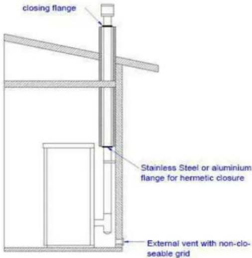
text_image
closing flange Stainless Steel or aluminium flange for hermetic closure External vent with non-clo- seable gridEXTERNAL VENT PIPE:
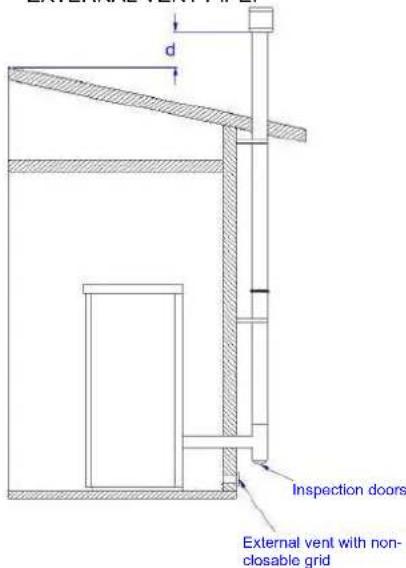
text_image
d Inspection doors External vent with non- closable grid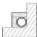
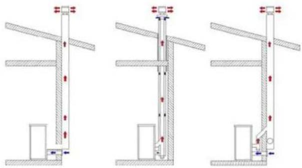
Examples of vent pipe
Steel vent pipe with double chamber insulated with material resistant to 400°C. Optimum efficiency.
Refractory vent pipe with insulated double chamber and external coating in lightweight concrete. Optimum efficiency.
text_image
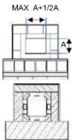
MAX A+1/2A AAvoid vent pipes with internal rectangular section whose ratio between the larger and smaller side is greater than 1.5. Poor efficiency
Traditional clay vent pipe with cavities. Optimum efficiency.
02.1 CHIMNEY COWL
A properly installed chimney cowl ensures optimum stove functioning. The anti-downdraught chimney cowl consists of a number of components whose outlet section sum always doubles the vent pipe section. Make sure the chimney cowl is at least 150cm above the roof top so that it is fully exposed to the wind. The chimney cowls must:
• have useful outlet section that is at least twice that of the vent pipe.
- be made in such a way as to prevent the penetration of rain or snow.
- be constructed in such a way as to ensure, in the event of winds coming from any direction, the evacuation of combustion products.
- be free of mechanical intake auxiliaries.
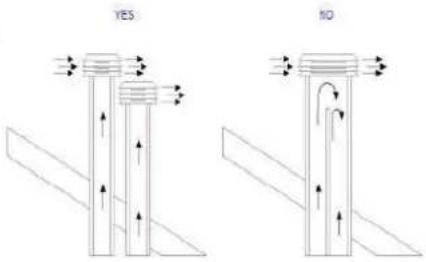
text_image
YES NO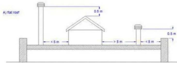
text_image
A) flat roof 0.5 m < 5 m > 5 m < 5 m 0.5 m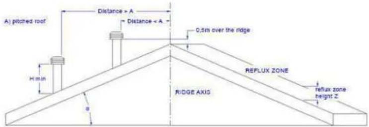
text_image
A) pitched roof Distance > A Distance < A 0,5m over the ridge H min a RIDGE AXIS REFLUX ZONE reflux zone height Z| Roof pitch [°] | Horizontal width of reflux zone measured from top A axis [m] | Minimum height from roof for discharging exhaust fumes H min =Z+0.50m | Height of reflux zone Z [m] |
| 15 1.85 | 1.00 0.50 | ||
| 30 1.50 | 1.30 0.80 | ||
| 45 1.30 | 2.00 1.50 | ||
| 60 1.20 | 2.60 2.10 |
02.2 DRAUGHT
Fumes heat up during combustion, increasing their volume. Their density is therefore lower than the one of the surrounding colder air.
This difference between the inside and outside temperatures of the chimney results in a negative pressure which increases proportionally to the vent pipe length and the temperature.
The draught must be stronger than the fume circulation resistance so that all exhaust fumes generated during combustion inside the stove are drawn upwards through the outlet and the vent pipe. Many weather conditions affect the vent pipe functioning, such as rain, fog, snow, altitude, and wind being the most important as it can create both negative pressure and dynamic loading.
The wind action varies depending on whether it is ascending, descending or horizontal.
- Ascending wind always results in an increased negative pressure and draught.
• Horizontal wind results in an increased negative pressure as long as the chimney cowl was properly installed. - Descending wind always diminishes the negative pressure, sometimes inverting it.
Excess draught causes an increase in the combustion temperature and consequently a loss in stove efficiency.
A part of the combustion fumes is drawn up through the vent pipe together with small pellet particles before combustion reducing stove efficiency, increasing fuel consumption and resulting in the emission of polluting fumes.
At the same time the high fuel temperature, due to an excess amount of oxygen, wears down the combustion chamber sooner than expected.
On the other hand, poor draught slows down combustion resulting in a decrease in the stove temperature, fume spillage inside the room, a loss of stove efficiency and dangerous build-up in the vent pipe.
In order to avoid excessive draught it is appropriate to use:
Draught regulator
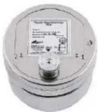
text_image
Close-up of a metallic cylindrical device with printed label and control knob visible02.3 STOVE EFFICIENCY
Highly efficient stoves may pose difficulties for fume extraction.
In order for a vent pipe to work properly its internal temperature must increase as a consequence of the fumes generated during combustion.
Importantly, the efficiency of a heater is determined by its ability to transfer most of the heat produced to the environment to be heated: consequently, the greater the efficiency of the stove, the "colder" the residual fumes of combustion, and consequently, the lower the "draft".
A traditional chimney flue, with a rough design and insulation, is more efficient if used with a traditional open fireplace or a poor quality stove where most of the heat is lost with the fumes.
Therefore, purchasing a quality stove often entails modifying the existing chimney flue to obtain a better insulation, even when it already works properly with old appliances.
Poor draught results in the stove not operating when hot or in smoke spillage.
- Connecting the stove pipe to an existing chimney flue that has already been used with an old appliance is a common mistake. In this way two solid-fuel appliances share the same chimney flue, which is wrong and dangerous.
- If the two appliances are used simultaneously, the fume load might exceed the existing chimney flue capacity resulting in downdraught. If only one appliance is used, the fume heat will facilitate draught but the cold air coming from the other appliance not in use will cool down exhaust fume temperature again blocking the draught.
- Besides the problems described so far, if the two appliances are placed on different levels the communicating vessel principle might be interfered with, causing combustion fumes to be drawn in an irregular and unforeseeable way.
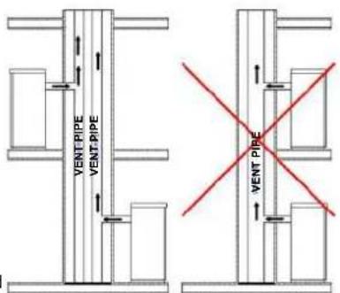
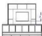
text_image
VENT PIPE VENT PIPE VENT PIPEUsing coaxial tubes the air will be pre-warmed contributing to improved combustion and lower emissions into the atmosphere.
Follow the instructions before installing your stove.
Select the position where the stove is to be installed and:
- Arrange the connection to the vent pipe for fume extraction
- Arrange the external air intake (combustion air)
- Arrange the connection to the earthed mains
- The electrical system of the room where the stove is to be installed must be earthed, otherwise the control board may not work properly.
- Place the stove on the floor in a convenient position for the connection to the vent pipe and close to the combustion air intake.
- The appliance must be installed on a floor with an adequate load-bearing capacity.
- Should the existing floor not comply with the requirement above, proper measurements must be taken (for instance, the installation of a load distribution plate).
- All the structures which could catch fire if exposed to excessive heat must be protected.
Floors made from wood or inflammable materials must be protected using non-combustible materials (e.g. 4mm-thick sheet metal or ceramic glass).
- The appliance installation must ensure easy access for cleaning the stove, exhaust pipes and vent pipe.
- This appliance is not suitable to be installed on a shared vent pipe.
- During normal operation, the stove draws air from the room where it is installed. Therefore, an external air intake must be positioned at the same height of the pipe located on the stove back. Exhaust fume pipes must be suitable for pellet stoves and must therefore be made from coated steel or stainless steel, with a diameter of 8cm and fitted with adequate gaskets.
- The combustion air intake must be connected directly to the outside or to adjacent rooms provided they are fitted with external air supply vents and are not used as bedrooms or bathrooms or, whenever a fire hazard exists, as storage rooms, garages, combustible material warehouses, etc. The air vents must be placed in such a way that they cannot be clogged either from the outside or inside and must be protected using a grille, a metal mesh or other suitable means provided they do not reduce the minimum section.
- If the stove is to be installed in rooms where it is surrounded by combustible materials (e.g. furniture, wood cladding, etc.), the following minimum clearances must be complied with:
natural_image
Three technical diagrams showing vertical structural components with arrows indicating force or movement, no text or symbols present.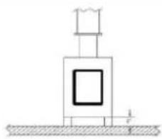
natural_image
Simple line drawing of a mechanical or structural component with no visible text, numbers, or symbols.PELLET STOVES and AIR STOVES
text_image
PELLE
text_image
Technical diagram showing a mechanical or structural component with labeled dimensions and componentsCOMBUSTABLE
NON-FLAMMABLE
COMBUSTABLE
NON-FLAMMABLE
AIR STOVE 13,5 KW (15) SPC-15
| REAR WALL P = 120 | mm |
| SIDE WALL L = 300 | mm |
| FLOORING F = - | mm |
| FRONT R = 100 | mm |
AIR STOVE 13,5 KW (15) SPC-15
| REAR WALL P = 120 | mm |
| SIDE WALL L = 200 | mm |
| FLOORING F = - | mm |
| FRONT R = 100 | mm |
AIR STOVE 18 KW (19,5) SPC-19,5
| REAR WALL P = 120 | mm |
| SIDE WALL L = 300 | mm |
| FLOORING F = - | mm |
| FRONT R = 100 | mm |
AIR STOVE 18 KW (19,5) SPC-19,5
| REAR WALL P = 120 | mm |
| SIDE WALL L = 200 | mm |
| FLOORING F = - | mm |
| FRONT R = 100 | mm |
AIR STOVE 18,5 KW (20,5) GP-20
| REAR WALL P = 80 | mm |
| SIDE WALL L = 200 | mm |
| FLOORING F = - | mm |
| FRONT R = 100 | mm |
AIR STOVE 18,5 KW (20,5) GP-20
| REAR WALL P = 80 | mm |
| SIDE WALL L = 100 | mm |
| FLOORING F = - | mm |
| FRONT R = 100 | mm |
PELLET KITCHEN 6,7 KW (7,5) CPV-7627
(free-standing installation)
| REAR WALL P = 10 | mm |
| SIDE WALL L = 200 | mm |
| FLOORING F = - | mm |
| FRONT R = 1000 | mm |
PELLET KITCHEN 6,7 KW (7,5) CPV-7627
(free-standing installation)
| REAR WALL P = 10 | mm |
| SIDE WALL L = 100 | mm |
| FLOORING F = - | mm |
| FRONT R = 1000 | mm |
PELLET KITCHEN 6,7 KW (7,5) CPV-7627
(recessed stove)
| REAR WALL P = 10 | mm |
| SIDE WALL L = 10 | mm |
| FLOORING F = - | mm |
| FRONT R = 1000 | mm |
PELLET KITCHEN 6,7 KW (7,5) CPV-7627
(recessed stove)
| REAR WALL P = 10 | mm |
| SIDE WALL L = 10 | mm |
| FLOORING F = - | mm |
| FRONT R = 1000 | mm |
PELLET KITCHEN with OVEN 8,6 KW (9,3)
CPF-85
| REAR WALL P = 50 | mm |
| SIDE WALL L = 50 | mm |
| FLOORING F = - | mm |
| FRONT R = 1000 | mm |
PELLET KITCHEN with OVEN 8,6 KW (9,3)
CPF-85
| REAR WALL P = 50 | mm |
| SIDE WALL L = 50 | mm |
| FLOORING F = - | mm |
| FRONT R = 1000 | mm |
AIR-TIGHT STOVES SLIM 7 KW (8) SPE7
| REAR WALL P = 50 | mm |
| SIDE WALL L = 300 | mm |
| FLOORING F = - | mm |
| FRONT R = 1000 | mm |
PELLET STOVES 5 KW (6) SP6
| REAR WALL P = 250 | mm |
| SIDE WALL L = 300 | mm |
| FLOORING F = - | mm |
| FRONT R = 1000 | mm |
PELLET STOVES 8 KW (9) SPCT8
| REAR WALL P = 100 | mm |
| SIDE WALL L = 250 | mm |
| FLOORING F = - | mm |
| FRONT R = 1000 | mm |
PELLET STOVES 7,5 KW (8,6) SPSV
| REAR WALL P = | 200 mm |
| SIDE WALL L = | 200 mm |
| FLOORING F = - | mm |
| FRONT R = 1000 | mm |
PELLET STOVES6,5 KW (7,5) SPIN7,5AT
| REAR WALL P = | 300- mm |
| SIDE WALL L = | 150- mm |
| FLOORING F = | 60- mm |
| FRONT R = 1000 | mm |
PELLET STOVES 10,5 KW (12) ANGLE
| REAR WALL P = - | mm |
| SIDE WALL L = - | mm |
| FLOORING F = - | mm |
| FRONT R = 1000 | mm |
AIR-TIGHT STOVES SLIM 7 KW (8) SPE7
| REAR WALL P = 50 | mm |
| SIDE WALL L = 200 | mm |
| FLOORING F = - | mm |
| FRONT R = 1000 | mm |
PELLET STOVES 5 KW (6) SP6
| REAR WALL P = 250 | mm |
| SIDE WALL L = 200 | mm |
| FLOORING F = - | mm |
| FRONT R = 1000 | mm |
PELLET STOVES 8 KW (9) SPCT8
| REAR WALL P = 100 | mm |
| SIDE WALL L = 150 | mm |
| FLOORING F = - | mm |
| FRONT R = 1000 | mm |
PELLET STOVES 7,5 KW (8,6) SPSV
| REAR WALL P = | 150 mm |
| SIDE WALL L = | 150 mm |
| FLOORING F = - | mm |
| FRONT R = 1000 | mm |
PELLET STOVES6,5 KW (7,5) SPIN7,5AT
| REAR WALL P = | 200- mm |
| SIDE WALL L = | 100- mm |
| FLOORING F = | 60- mm |
| FRONT R = 1000 | mm |
PELLET STOVES 10,5 KW (12) ANGLE
| REAR WALL P = - | mm |
| SIDE WALL L = - | mm |
| FLOORING F = - | mm |
| FRONT R = 1000 | mm |
AIR-TIGHT STOVES SLIM 8,5 KW (9,5) SPE8,5
| REAR WALL P = 50 | mm |
| SIDE WALL L = 150 | mm |
| FLOORING F = - | mm |
| FRONT R = 1000 | mm |
AIR-TIGHT STOVES SLIM 8,5 KW (9,5) SPE8.5
| REAR WALL P = 50 | mm |
| SIDE WALL L = 50 | mm |
| FLOORING F = - | mm |
| FRONT R = 1000 | mm |
PELLET STOVES DUCT. 14 KW (15) SPV-M13
| REAR WALL P = 200 | mm |
| SIDE WALL L = 300 | mm |
| FLOORING F = - | mm |
| FRONT R = 1000 | mm |
PELLET STOVES DUCT. 14 KW (15) SPV-M13
| REAR WALL P = 200 | mm |
| SIDE WALL L = 200 | mm |
| FLOORING F = - | mm |
| FRONT R = 1000 | mm |
PELLET STOVES with OVEN 7,5 KW (8,5) SPF8.5
| REAR WALL P = 200 | mm |
| SIDE WALL L = 300 | mm |
| FLOORING F = - | mm |
| FRONT R = 1000 | mm |
PELLET STOVES with OVEN 7,5 KW (8,5) SPF8.5
| REAR WALL P = 200 | mm |
| SIDE WALL L = 200 | mm |
| FLOORING F = - | mm |
| FRONT R = 1000 | mm |
PELLET STOVES SLIM 4 KW (5,5) SP4
| REAR WALL P = 40 | mm |
| SIDE WALL L = 300 | mm |
| FLOORING F = - | mm |
| FRONT R = 1000 | mm |
PELLET STOVES SLIM 4 KW (5,5) SP4
| REAR WALL P = 40 | mm |
| SIDE WALL L = 200 | mm |
| FLOORING F = - | mm |
| FRONT R = 1000 | mm |
PELLET STOVES DUCT. 7,5 KW (9) SPCA7,5
| REAR WALL P = | 250 mm |
| SIDE WALL L = | 250 mm |
| FLOORING F = | - mm |
| FRONT R = | 1000 mm |
PELLET STOVES DUCT. 7,5 KW (9) SPCA7,5
| REAR WALL P = | 200 mm |
| SIDE WALL L = | 200 mm |
| FLOORING F = | - mm |
| FRONT R = | 1000 mm |
PELLET STOVES SLIM 4 KW (5,5) SP4
| REAR WALL P = | 40 mm |
| SIDE WALL L = | 300 mm |
| FLOORING F = | - mm |
| FRONT R = | 1000 mm |
PELLET STOVES SLIM 4 KW (5,5) SP4
| REAR WALL P = | 40 mm |
| SIDE WALL L = | 200 mm |
| FLOORING F = | - mm |
| FRONT R = | 1000 mm |
PELLET STOVES 11,5 KW (13,5) SPV-M11S
| REAR WALL P = 200 | mm |
| SIDE WALL L = 300 | mm |
| FLOORING F = - | mm |
| FRONT R = 1000 | mm |
PELLET STOVES SLIM DUCT. 9,3 KW (10,5) SPCS9
| REAR WALL P = | 50 mm |
| SIDE WALL L = | 200 mm |
| FLOORING F = - | mm |
| FRONT R = 1000 | mm |
PELLET STOVES SLIM 6,5 KW (7,5)
| REAR WALL P = 10 | mm |
| SIDE WALL L = 300 | mm |
| FLOORING F = - | mm |
| FRONT R = 1000 | mm |
PELLET STOVES SLIM 9 KW (11) SPVM-9
| REAR WALL P = 100 | mm |
| SIDE WALL L = 250 | mm |
| FLOORING F = - | mm |
| FRONT R = 1000 | mm |
PELLET STOVES 8 KW (9,3) SPSC8C - SPSC8
| REAR WALL P = | 200 mm |
| SIDE WALL L = | 200 mm |
| FLOORING F = | - mm |
| FRONT R = | 1000 mm |
PELLET STOVES 11,5 KW (13,5) SPV-M11S
| REAR WALL P = 200 | mm |
| SIDE WALL L = 200 | mm |
| FLOORING F = - | mm |
| FRONT R = 1000 | mm |
PELLET STOVES SLIM DUCT. 9,3 KW (10,5) SPCS9
| REAR WALL P = | 50 mm |
| SIDE WALL L = | 150 mm |
| FLOORING F = - | mm |
| FRONT R = 1000 | mm |
PELLET STOVES SLIM 6,5 KW (7,5)
| REAR WALL P = 10 | mm |
| SIDE WALL L = 200 | mm |
| FLOORING F = - | mm |
| FRONT R = 1000 | mm |
PELLET STOVES SLIM 9 KW (11) SPVM-9
| REAR WALL P = 100 | mm |
| SIDE WALL L = 150 | mm |
| FLOORING F = - | mm |
| FRONT R = 1000 | mm |
PELLET STOVES 8 KW (9,3) SPSC8C - SPSC8
| REAR WALL P = | 100 mm |
| SIDE WALL L = | 100 mm |
| FLOORING F = | - mm |
| FRONT R = | 1000 mm |
| 9,5 KW INSERTS11) IP9,5 | 6,5 KW INSERTS(7,5) IPGN | |
| REAR 100 180 | ||
| LATERAL 100 180 | ||
| FRONT 1500 1000 | ||
| FLOOR 50 | 10 | |
| A cm2 | 500 450 | |
| B cm2 | 500 450 | |
PELLETI INSERTS
text_image
Technical diagram showing cross-sectional views and labeled components of a mechanical or architectural assembly, with annotations A, B, C, D.Only AIR-TIGHT STOVES
This stove is an air-tight stove. If properly connected by means of a suction tube, these stoves draw the combustion air and the air necessary for glass cleaning directly from outside and not from the room where they are installed, preserving the oxygen in the room. Using coaxial tubes the air will be prewarmed contributing to improved combustion and lower emissions into the atmosphere. Ideal for passive houses, they offer best comfort at the lowest cost. The stove works even if not connected to the external air intake.
Besides complying with the minimum clearances set above, we also recommend installing heat-resistant fireproof insulating panels (rock wool, cellular concrete, etc.).
The following is recommend:
Promasil 1000
Classification temperature: 1000 °C
Density: 245 kg/m³
Shrinkage at reference temperature, 12 h: 1.3/1000°C %
Cold crushing strength: 1.4 MPa
Bending strength: 0.5 MPa
Reversible thermal expansion: 5.4x10 ^-6 m/mK
Specific heat capacity: 1.03 Kj/kgK
Thermal conductivity λ:
200 °C → 0.07 W/mK
400 °C → 0.10 W/mK
600^ 0.14W / mK
800 °C → 0.17 W/mK
Thickness: 40 mm
- When it is operational, the stove can cause a negative pressure in the room where it is installed. Therefore there should not be in the same room other naked flame devices, with the exception only of type c stoves (airtight).
- Make sure that the stove can draw the necessary quantity of combustion air: this must be from an open space (i.e. a space without exhaust blowers or providing adequate ventilation) or directly from outside.
- Do not install the stove in bedrooms or bathrooms.
- Unpack the stove: be careful not to damage the product at the time of unpacking.
- Check the stove's legs and adjust them so that the stove is stable.
- Place the stove so that the door and any window openings are not against the walls.
• After connecting the stove to the combustion air inlet join the coupling device to the vent pipe.
INSTALLATION EXAMPLE:
Exhaust pipes must never be fitted pointing downwards or horizontally so that fumes are discharged directly through the external wall.
04 INSTALLATION
Pursuant to current regulations on installation, the stove must be placed in a well-ventilated place to guarantee efficient combustion and proper functioning. The room must have a volume equal to or higher than 20 m3. An air vent is required to guarantee efficient combustion (40 m3/h air). It can be connected directly to the outside or to adjacent rooms provided they are fitted with external air supply vent (Φ 80mm) and are not used as a bedroom or bathroom or, whenever a fire hazard exists, as storage room, garage, combustible material warehouse, etc. The air vents must be placed in such a way that they cannot be clogged either from the outside or inside and must be protected using a grille, a metal mesh or other suitable means provided they do not reduce the minimum cross-section.
When working the stove may create a negative pressure inside the room where it is fitted. Therefore, it is not possible to have more than one open flame appliance installed in the same room (the type "C" boilers "room sealed" are the only exception unless provided with their own air vent).
The stove must be installed far from curtains, armchairs, furniture or other inflammable materials.
The stove must not be installed in case of explosive atmospheres or in rooms that may become potentially explosive due to the presence of appliances, materials or powders causing gas leaks or catching fire easily from sparks. When installing a stove make sure to guarantee adequate clearance from all finishes or beams made from combustible materials, keeping them far from its irradiation area. Moreover, make sure to prevent heat build-up in the recess, which will result in the insert malfunctioning, by guaranteeing the required air space, i.e. by respecting minimum clearances and making ventilation slots with a total surface area of 80 cm2 cm.
The electrical connection must be performed by qualified personnel who install circuit breakers upstream of the appliance.
Special attention should be paid when the stove is parts of the system and all equipment must operate as planned.
Avoid installations with electric cables that run close to fume pipes or hot components that are suitably insulated.
The voltage is 230 V while the frequency is 50 Hz.
The electrical system where it is connected must be fitted with a conductor as required by the Regulations 73/23 EEC and 93/98 EEC.
04.1 PELLET STOVES
(Electronics p. 56 - 58 - 60 - 62 - 64 - 71)
IMPORTANT: THE LENGTH OF THE FLUE DUCT MUST BE OF MAX. 6 METERS WITH A DIAMETER OF 80 mm; EVERY 90° CURVE OR (T) CONNECTION IS CONSIDERED AS 1 METER OF PIPE.
PRIOR TO THE CHIMNEY CONNECTION, TO ENSURE THE CORRECT PERFORMANCE OF THE STOVE, YOU MUST RESPECT THE FOLLOWING TYPES OF INSTALLATION:
SLIM PELLET STOVE 4 KW (5,5) SP4 must installed with a "T" connection and at least 1 meter of 80mm pipe certified to EN 1856-2.
PELLET STOVE 5 KW (6) SP6 must be installed with a "T" connection and at least 1 meter of 80 mm pipe certified to EN 1856-2.
PELLET STOVE 8 KW (9) SPCT8 must be installed with a "T" connection and at least 1 meter and 1 90° curve pipes certified to EN 1856-2.
DUCT. PELLET STOVE 7,5 KW (9) SPCA7,5 must be installed with a "T" connection and at least 1 meter and 1 curve 90^ 80 mm pipe certified to EN 1856-2..
PELLET STOVE 8 KW (9,3) SPSC8C/SCSC8 must be installed with a "T" connection and at least 1 meter and 1 curve 90° Φ80 mm pipe certified to EN 1856-2.
PELLET STOVE 11,5 KW (13,5) SPV-M11S must be installed with a "T" connection and at least
DUCT. PELLET STOVE 14 KW (15) SPV-M13 must be installed with a "T" connection and at least 1 curve of 90° Φ80mm pipe certified to EN 1856-2.
SLIM PELLET STOVE 6,5 KW (7,5) must be installed with a "T" connection and at least 1 meter of Φ80 pipe certified to EN 1856-2.
SLIM PELLET STOVE 9KW (11) SPVM-9 must be installed with a "T" connection and at least 1 meter of 80mm pipe certified to EN 1856-2.
DUCT. SLIM PELLET STOVE 9,3 KW (10,5) SPCS9 must be installed with a "T" connection and at least 1 meter of 80 mm pipe certified to EN 1856-2.
INSTALLAZION CORNER STOVE
During installation, the installer must also take into consideration the convective air sections: the structure housing the appliance must be fitted with ventilation slots.
IMPORTANT: THE LENGTH OF THE FLUE DUCT MUST BE OF MAX. 6 METERS WITH A DIAMETER OF 80 mm; EVERY 90° CURVE OR (T) CONNECTION IS CONSIDERED AS 1 METER OF PIPE.
If you want to install the stove with rear outlet, please break the pre-cut in the back and then install the pipes.
USING THE OVEN
The outputs are set as follows:
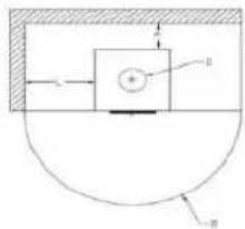
P1, P2, P3, P4, P5, OVEN. Using the powers from P1 to P5 the stove works normally, as a classic stove, with predefined caloric power and room ventilation. Pressing the 1 button you can change the Ambient Set. Using the OVEN mode the stove works according to the temperature of the oven. As you can see, inside the oven there is a temperature probe which controls the internal temperature. The caloric power of the stove will be automatic: depending on the temperature of the oven, it will choose autonomously the power in order to keep a constant temperature inside the oven. The oven temperature can be set by pressing the display key 1 only and exclusively in the OVEN function. In case the oven temperature exceeds the set temperature, the ambient ventilation will bring at par the temperature values.
DESCRIPTION COMPONENTS
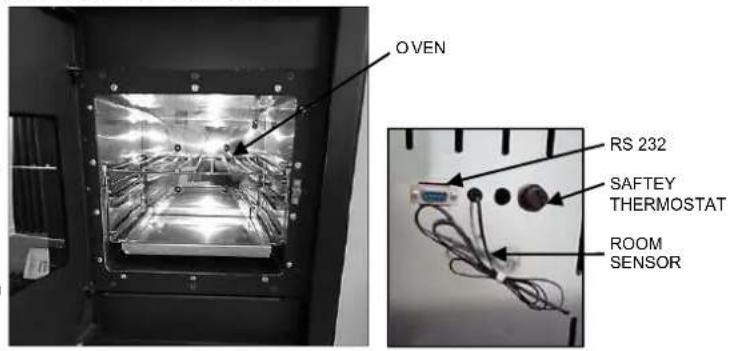
text_image
OVEN RS 232 SAFTEY THERMOSTAT ROOM SENSORTIMER
Once selected the TIMER OVEN mode, press the (P2) power button and then the ON/OFF button. At this point, it is proposed a timer in minutes (default 60 minutes) that with the keys (P1) and (P2) allows to change the time, which can be confirmed with the ON/OFF button. After the set time, the board's buzzer will beep for 1 minute with a 2 beep-per-second frequency.
Only for the stove (BISCOTTO)
WARNING: If you want to channel the stove air in a different environment, you should know that the air is drawn from the room where the stove is installed, so when the food is being cooked it is possible that the smell of the stoves is also transmitted in the canalized room.
04.3 PELLET INSERTS
(Electronics p. 56 - 62 - 71)
IMPORTANT: THE LENGTH OF THE FLUE DUCT MUST BE OF MAX. 6 METERS WITH A DIAMETER OF 80 mm; EVERY 90° CURVE OR (T) CONNECTION IS CONSIDERED AS 1 METER OF PIPE.
11 KW INSERT - PULL FOR LOADING
After fixing the insert, lock the grids with the supplied screws and fasten the display.
Pellet feeding: to load the pellet you need to switch off the machine and pull it out.
ATTENTION: the insert it equipped with an electrical safety device: when pulled out, the safety device cuts off the power supply. YOU MUST switch off the device to load the pellet (OFF). By doing so, you will prevent any fumes inside the chamber from being released into the room.
11 KW INSERTS
Suitably isolated the beam above the insert if present. Any extraordinary maintenance operations shall be carried out by authorised staff, with the insert switched off, after slightly lifting its front side and pulling it out.
Pellet feeding: remove the upper drawer and fill it with pellet. This operation can also be performed while the insert is running.
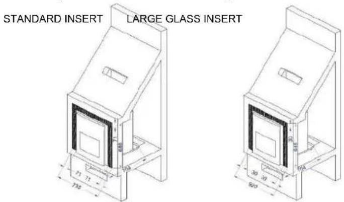
text_image
STANDARD INSERT LARGE GLASS INSERT 71 71 732 80 80 80 920 920PULL OUT THE INSERT AND REMOVE IT FROM THE GUIDES
text_image
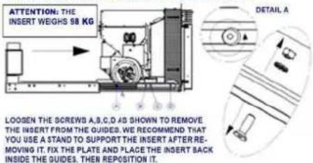
ATTENTION: THE INSERT WEIGHS 58 KG DETAIL A LOOGEN THE SCREWS A,B,C,D AS SHOWN TO REMOVE THE INSERT FROM THE GUIDES, WE RECOMMEND THAT YOU USE A STAND TO SUPPORT THE INSERT AFTER RE- MOVING IT. FIX THE PLATE AND PLACE THE INSERT BACK INSIDE THE GUIDES, THEN REPOSITION IT.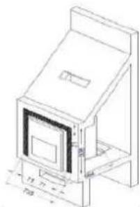
natural_image
Technical line drawing of a mechanical component with dimension annotations (no readable text or symbols)Ducting system
The devices which can be equipped with ducting systems are the 11KW inserts, not removed for loading.
After installing the insert, fix the bracket with the second blower to the wall in a comfortable position and if possible, not above the flexible pipe supplied with the product. Carefully tighten the clamps and connect the blower to another flexible pipe to channel the air into another room. The second fan setting is on page 57.
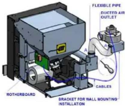
text_image
FLEXIBLE PIPE DUCTED AIR OUTLET A CABLES MOTHERBOARD BRACKET FOR WALL MOUNTING INSTALLATIONPRIOR TO THE CHIMNEY CONNECTION, TO ENSURE THE CORRECT PERFORMANCE OF THE STOVE, YOU MUST RESPECT THE FOLLOWING TYPES OF INSTALLATION:
7.5 KW INSERTS
The chimney flue must be installed with 1 m of pipe of ∅80mm certified to EN 1856-2.
IMPORTANT: THE LENGTH OF THE FLUE DUCT MUST BE OF MAX. 6 METERS WITH A DIAMETER OF 80 mm; EVERY 90° CURVE OR (T) CONNECTION IS CONSIDERED AS 1 METER OF PIPE.
PRIOR TO THE CHIMNEY CONNECTION, TO ENSURE THE CORRECT PERFORMANCE OF THE STOVE, YOU MUST RESPECT THE FOLLOWING TYPES OF INSTALLATION:
The pellet stove must be fitted with a 0.5 m-long pipe (Φ 80 mm) certified to EN 1856-2 standard.
The pellet stove, depending on the model you have purchased, can be installed flush or with free-standing installation. In the case of free-standing installation respect the following distances from combustible wall, Page 50 – 51.
If you want to build the stove into other pieces of the kitchen, you can safely place the furniture close to the hob. The safety distance is given by the heads of the screws installed in the lid. You can close the space between the lid and the hob with a high-temperature-proof silicone, Page 50 – 51.
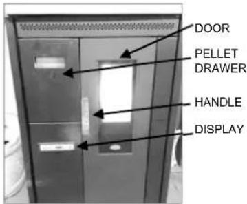
This type of stove combines the convenience of pellets with the proven tradition of an economic kitchen with which it is possible to prepare meals and heat the environment at the same time. Thanks to technology, in this case also not only is it possible to cook but the appliance was created to provide plenty of space to do so. In addition the pellets are easy to handle, both in terms of power and for the precise temperature management, with no mess or clutter. This economical ventilated pellet stove is equipped with a frontal pellet loading system that is very easy to use and which makes it extremely practical in everyday use. Its wide top plate, available in steel or glass ceramic, is perfect for cooking meals using the heat given off. The fume outlet is top or rear. In winter, the forced ventilation facilitates rapid and uniform heating of the entire environment while in summer it is possible to cook without forced ventilation. Conceived to be functional, the design was not secondary, in fact the large glass panel was intended to make the fire visible. Available in both the recessed and free-standing version.
DESCRIPTION COMPONENTS
text_image
DOOR PELLET DRAWER HANDLE DISPLAY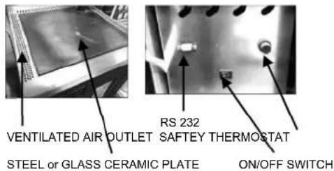
text_image
VENTILATED AIR OUTLET SAFETY THERMOSTAT STEEL or GLASS CERAMIC PLATE ON/OFF SWITCHBefore installing the stove rotate the rear upstand (if any), by loosening the screws.
To install the stove with rear exhaust, it is necessary to break the semi-cut on the rear and then install the pipes.
04.5 PELLET KITCHEN WITH OVEN
(Electronics p. 60 - 71)
IMPORTANT: THE LENGTH OF THE FLUE DUCT MUST BE OF MAX. 6 METERS WITH A DIAMETER OF 80 mm; EVERY 90° CURVE OR (T) CONNECTION IS CONSIDERED AS 1 METER OF PIPE.
PRIOR TO THE CHIMNEY CONNECTION, TO ENSURE THE CORRECT PERFORMANCE OF THE STOVE, YOU MUST RESPECT THE FOLLOWING TYPES OF INSTALLATION:
The pellet stove with oven must be installed with 0,5 meters of pipe 80mm certified according to the EN 1856-2 norm.
The pellet stove with oven can be flush mounted or it can have a free installation. Page 50 - 51.
If you want to build the stove into other pieces of the kitchen, you can safely place the furniture close to the hob. The safety distance is given by the heads of the screws installed in the lid. You can close the space between the lid and the hob with a high-temperature-proof silicone. Page 50 – 51.
Before installing the kitchen it is necessary to rotate the rear backsplash (if present), by unscrewing the screws.
If you want to install the stove with rear outlet please break the pre-cut in the back and then install the pipes.
USING THE OVEN
The powers are set as follows:
P1, P2, P3, P4, P5, OVEN. Using the powers from P1 to P5 the stove works normally, as a classic stove, with predefined caloric power and room ventilation. Pressing the 1 button you can change the Ambient Set. Using the OVEN mode the stove works according to the temperature of the oven. As you can see, inside
the oven there is a temperature probe which controls the internal temperature. The caloric power of the stove will be automatic: depending on the temperature of the oven, it will choose autonomously the power in order to keep a constant temperature inside the oven. The oven temperature can be set by pressing the display key 1 only and exclusively in the OVEN function. In case the oven temperature exceeds the set temperature, the ambient ventilation will bring at par the temperature values.
TIMER
Once selected the TIMER OVEN mode, press the (P2) power button and then the ON/OFF button. At this point, it is proposed a timer in minutes (default 60 minutes) that with the keys (P1) and (P2) allows to change the time, which can be confirmed with the ON/OFF button. After the set time, the board's buzzer will beep for 1 minute with a 2 beep-per-second frequency.
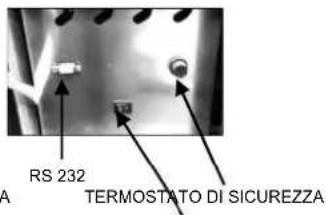
DESCRIPTION COMPONENTS
text_image
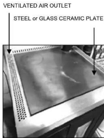
VENTILATED AIR OUTLET STEEL or GLASS CERAMIC PLATE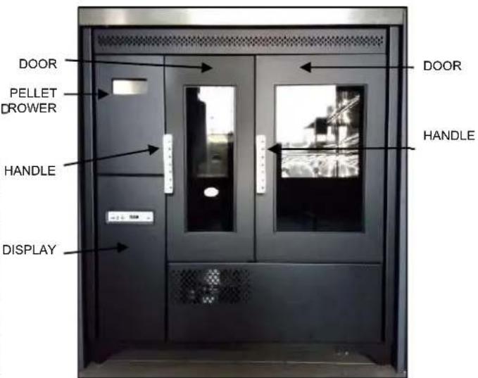
text_image
DOOR PELLET DROWER HANDLE DISPLAY DOOR HANDLEIMPORTANT: THE LENGTH OF THE FLUE DUCT MUST BE OF MAX. 6 METERS WITH A DIAMETER OF 80 mm; EVERY 90° CURVE OR (T) CONNECTION IS CONSIDERED AS 1 METER OF PIPE.
DUCTED STOVE FUTURA 15 KW AND FUTURA 19,5 KW
The 40 Kg pellet hopper, remote control, DFCS control system for the combustion air and the air-tight system renders it ideal for passive houses, as it does not take combustion air from the environment. It can be fitted with upper or rear
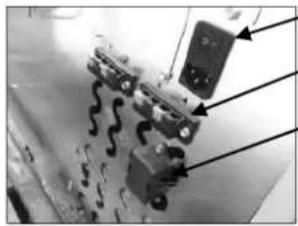
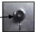
DESCRIPTION COMPONENTS
natural_image
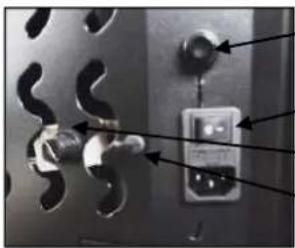
Close-up of mechanical components with no visible text or symbolsON/OFF SWITCH
THERMOSTATS or EXTERNAL
SENSORS
REMOTE CONTROL RECEIVER
EMERGENCY SWITCH
PELLET HOPPER LID
PELLET HOPPER LID GASKET
SAFETY THERMOSTAT
natural_image
Close-up of a small electronic device with a mounted sensor or sensor array, no visible text or symbols.
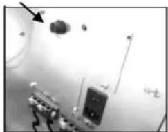
natural_image
Exterior view of a medical or laboratory instrument with a screen and control panel (no visible text or symbols)couplings for the ducts and it can be connected to an already existing thermostat or can be set to start when the room temperature reaches or use ambient probes that regulate the ventilation speed and the relative power of the stove.
The fittings of the ducted air pipes have a diameter of 80 mm. For long distances, or if you need to pass through walls made of flammable material, we recommend that you use insulated pipes. The insulation consists of a 50 mm thick insulating wall and therefore, the hole through wich the pipes will pass should have a diameter of at least 140 mm. We recommend that you use gaskets so as to prevent any air leaks; the use of flexible tubes is not recommended as they might break during the connection and also, the smooth ones are susceptible to pressure drops. However, you can install 100 mm diameter pipes.
The fume outlet can be located on the upper side or on the rear side of the stove.
You can decide between the rear and the top fume outlet based on the location of the vent pipe. If you opt for a rear fume outlet, you need to cut a piece of pipe so as to determine the exact distance at which you have to make the connection to the curve that reaches the rear outlet.
text_image
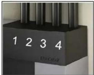
1 2 3 4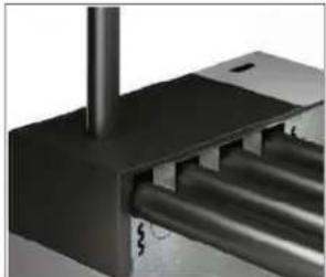
natural_image
Close-up of a black mechanical component with cylindrical and rectangular parts, no visible text or symbolsThe air motor of room number 1, is the furthest to the left, as you look from the tank side. The air motor of room number 4, is the furthest to the right.
Connect the 4 ducted air pipes as described above and then install the sensors or the thermostats. You can connect 4 sensors (included in the supply) or 4 thermostats (not included in the supply). You can connect the sensors or the thermostats using any 2-pole cable with double insulation available on the market. The clamps on the back of the stove are numbered and correspond to the numbers of the ducting outlets.
ATTENTION (limitations on installing sensors or thermostats):
- Room number 1 can be connected to a sensor but not to an actual thermostat: the remote control will act as a thermostat. Therefore, if you want a thermostat in room
number 1, you will need to install the remote control system. However, install a sensor on input 1.
• If you install a thermostat in room 2, you must install one in room 3 too.
• If you install the sensor in room 2 you can freely install the thermostat in room 3.
Below you will find a table reporting the available configurations for the installation of thermostats or sensors:
Possible configurations
| ROOM 1 | Sensor / remote control | Sensor / remote control | Sensor / remote control | Sensor / remote control | Sensor / remote control | Sensor / remote control |
| ROOM 2 | Sensor | Sensor | Thermostat | Sensor | Sensor | Thermostat |
| ROOM 3 | Sensor | Thermostat | Thermostat | Sensor | Thermostat | Thermostat |
| ROOM 4 | Sensor | Sensor | Sensor | Thermostat | Thermostat | Thermostat |
If you want to install thermostats you also have to contact the qualified technician who will change the settings of the parameters.
ATTENTION (limitations concerning the ventilation):
- As you will see in the following pages of this manual, the settings made on blower 3 are identical with those made on blower 4: by changing the setting on blower 3 you will automatically change the settings of blower 4.
PAY UTMOST ATTENTION WHEN CHOOSING THE ROOMS AND TAKE INTO CONSIDERATION THE SENSOR/THERMOSTAT LIMITATIONS, MAKING SURE THAT THE SPEED SETTINGS ON BLOWERS 3 AND 4 ARE THE SAME. THE STOVE DOES NOT WORK IF THE LID OF THE PELLET HOPPER IS OPEN.
04.7 AIR-TIGHT STOVES
(Electronics p. 66)
IMPORTANT: THE LENGTH OF THE FLUE DUCT MUST BE OF MAX. 6 METERS WITH A DIAMETER OF 80 mm; EVERY 90° CURVE OR (T) CONNECTION IS CONSIDERED AS 1 METER OF PIPE.
Although really thin (only 25 cm deep), this pellet stove ensures highDESCRIPTION OF COMPONENTS
performance in terms of heat output thanks to its air-tight structure that facilitates heat development and renders it suitable for heating up closed environments such as bedrooms, studios and bathrooms. It comes with glass door cleaner, remote control system with room temperature sensor that can manage up to 10 operating powers and DFSC (Dynamic Flow Control System).
A stove that heats up and enhances the design of the rooms thanks to its modern lines, rounded edges and door made entirely of screen-printed glass.
THE STOVE DOES NOT WORK IF THE LID OF THE PELLET HOPPER IS OPEN
natural_image
Close-up of a computer interface panel with ports and connectors (no visible text or symbols)EMERGENCY SWITCH
ON/OFF SWITCH
SAFETY THERMOSTAT
ROOM SENSOR
REMOTE CONTROL RECEIVER
05.1 ELECTRONICS WITH 6-BUTTON LED DISPLAY
(Pellet inserts - Canalized pellet stove)
p. 42 F-1
PROPER FUNCTIONING AND CONTROL ADJUSTMENT DEVICES
First connect the stove plug to the mains and load the pellet hopper. Be careful not to empty the entire bag at once. Perform this operation slowly.
DESCRIPTION OF PANEL
BUTTON (P1) - Temperature increase:
When in (SET TEMP) mode, use this button to increase the thermostat value from a minimum of 6^ C to a maximum of 41^ C. The selected value appears on the lower display, while the upper display shows the message SET. When modifying user and technician parameters, use this button to increase the parameter value. The selected value appears on the lower display. When in working mode, use this button to visualise the fume temperature on the lower display.
BUTTON (P2) - Temperature decrease:
When in (SET TEMP) mode, use this button to decrease the thermostat value from a maximum of 41^ C to a minimum of 06^ C. The selected value appears on the lower display, while the upper display shows the message SET.
When modifying user and technician parameters, use this button to decrease the parameter value. The selected value appears on the lower display. When in working mode, use this button to visualise the time on the lower display.
BUTTON (P3) - Set/menu:
Use this button to access (SET TEMP) temperature setting and user and technician parameter menu. Press P3 button repeatedly to cycle through all the parameters inside the menu. The upper display visualises the parameter label, while the lower display shows the relevant value.
BUTTON (P4) - ON/OFF Release:
Hold this button down for two seconds to manually switch the stove on or off respectively depending on its initial status (switched ON or OFF).
Should have any alarm blocked the stove, press this button to unlock it and subsequently switch it OFF.
When setting user/technician parameters, use this button to exit the menu at any setting step.
BUTTON (P5) - Heat output decrease:
When in working mode (ON), use this button to decrease the heat output from 5, maximum value, to 1. The selected value appears on the upper display.
BUTTON (P6) - Heat output increase:
When in working mode (ON), use this button to increase the heat output from 1, minimum value, to 5. The selected value appears on the upper display.
ECO - Temperature reached: When the required temperature is reached, the message ECO appears on the display. P5 and P6 buttons are disabled automatically. Change the set temperature to enable P5 and P6 buttons again and access the heat output setting.
ACRIVE CHRONO LED (L1):
The LED is on when UT1 user parameter is different from OFF in the menu and weekly programming or lap time can be set.
AUGER TUBE ON LED (L2):
The LED is on whenever the Auger tube is enabled and the motor, feeding the pellets in the combustion chamber, is working. This occurs during start-up and working mode.
REMOTE CONTROL RECEIVER LED (L3):
The LED flashes whenever the control panel receives a signal from the IR remote control to modify temperature/heat output.
ROOM THERMOSTAT LED (L4):
The LED is on whenever the room temperature is higher than the set temperature (external thermostat not in use). When using the external thermostat (if available), the LED is lit when the thermostat temperature is reached.
TEMPERATURE SETTING LED (L5):
The LED flashes when working in the user/technician menu or while setting the temperature (SET TEMP).
DISPLAY Status/Heat Output/Parameter label DISPLAY (D1):
It shows the board status during start-up phase.
During working mode, it shows the heat output set by the user.
When modifying user/technician parameters, it shows the label of the parameter in question.
DISPLAY Status/Time/Temperature/Parameter value DISPLAY (D2):
It shows the board status during start-up phase.
During working mode, it shows the temperature set by the user.
When modifying user/technician parameters, it shows the value of the parameter in question.
USER FUNCRIONS
Stove ignition
Hold down P4 for a few seconds to switch on the stove. The display shows that the stove is on. The stove goes into the pre-ventilation/pre-heating phase for 90 seconds. The stove enters the pre-load mode for the period of time indicated by Pr45 parameter. Meanwhile, the Auger tube rotates and continues to load pellets. At the end of the period of time set by Pr45 parameter, the system goes into the waiting phase whose duration is defined by Pr46 parameter. Then the loading phase begins at the speed set by Pr04 parameter. The Auger tube ON LED is on indicating that the Auger tube is working. The ignition plug switches off when fume temperature exceeds value under parameter Pr13, increasing by a gradient of approx. 3 C°/minute.
Pellet manual loading
Press P5 and P6 buttons simultaneously to load the pellets. This function is available only when the stove is switched off and cold.
Fire on
Once fume temperature has reached and exceeded Pr13 parameter value, the stove goes into the switching on mode (ACC). In this phase temperature stabilises for a period of time set by Pr02 parameter. In case the contrary is arrested and the error message (ALAR).
Stove operational
Once fume temperature has reached and exceeded Pr13 parameter value, maintaining it for the period of time set by Pr02 parameter, the stove enters the normal working mode. The upper display shows the heat output set by means of P5 and P6 buttons, while lower display shows room temperature.
Changing set heat output
During the normal operating mode (stove running) the user can change the heating capacity by means of the buttons P6 (increase) and P5 (decrease). The set heating capacity is displayed on the top screen.
Changing set room temperature
Press SET button (P3) to change room temperature and visualise the set room temperature (SET TEMP). Press P1 and P2 buttons to increase or decrease, respectively, the temperature value.
The new value is saved after approx. 3 seconds and the display goes back to normal.
Press P3 button (SET) to visualise the set room temperature (SET TEMP).
It will remain on the display for about 2 seconds.
When the set room temperature value is reached, the stove heat output is automatically set to the minimum value. ECO (Economy) message appears on the upper display and the room thermostat LED switches on.
Stove switch off
Hold down P4 button for approx. 2 seconds to switch off the stove. "OFF" appears on the upper display, while the lower display shows current time.
The Auger tube motor stops and the exhaust blower speed increases. The exchanger blower remains on until the fume temperature reaches a value below the preset Pr15 value. The exhaust blower switches off after approx. 10 minutes. Depending on the version, it may be necessary to wait the period of time set by Pr73 parameter before switching on the stove again. During the wait, P4 button is inactive and the following message appears asking users to wait until the end of the switching off phase (COOL FIRE).
The same happens whenever the fume temperature exceeds the maximum value set by Pr14 parameter.
Once the temperature falls again within the set range, the stove goes back to the normal working mode.
Burn pot cleaning
When the stove is in the working mode, the (STOP FIRE) mode is activated for the period set by Pr12 parameter at the intervals set by Pr03 parameter.
Programmable thermostat
The programmable thermostat function allows for the programming of the stove automatic switching on and off during the week.
Press P3 button twice to enter the programming mode. Press P3 button again to cycle through all the parameters available. Press instead P4 button to exit the programming at any time. The programmable thermostat parameters are listed below:
| Parameter Description Available values | |
| UT01 Current day setting and programmable thermostat enabling/disabling DAY1,...DAY7; OFF; | |
| UT02 Current time setting From 00 to 11 pm | |
| UT03 Current time minute setting From 00 to 60 | |
| UT04 ONLY FOR TECHNICIANS – DO NOT enter any setting | |
| UT05 PROGRAMME 1 switching-on time setting From 00:00 to 11:50 pm by 10' steps | |
| UT06 PROGRAMME 1 switching-off time setting From 00:00 to 11:50 pm by 10' steps | |
| UT07 Day selection with stove switching on according to PROGRAMME 1 ON/OFF for days from 1 to 7 | |
| UT08 PROGRAMME 2 switching-on time setting From 00:00 to 11:50 pm by 10' steps | |
| UT09 PROGRAMME 2 switching-off time setting From 00:00 to 11:50 pm by 10' steps | |
| UT10 Day selection with stove switching on according to PROGRAMME 2 ON/OFF for days from 1 to 7 | |
| UT11 PROGRAMME 3 switching-on time setting From 00:00 to 11:50 pm by 10' steps | |
| UT12 PROGRAMME 3 switching-off time setting From 00:00 to 11:50 pm by 10' steps | |
| UT13 Day selection with stove switching on according to PROGRAMME 3 ON/OFF for days from 1 to 7 | |
| UT14 PROGRAMME 4 switching-on time setting From 00:00 to 11:50 pm by 10' steps | |
| UT15 PROGRAMME 4 switching-off time setting From 00:00 to 11:50 pm by 10' steps | |
| UT16 Day selection with stove switching on according to PROGRAMME 4 ON/OFF for days from 1 to 7 |
Some parameters are described in detail below:
MEANING OF THE DISPLAY
| DAY 1 - Monday | DAY 2 - Tuesday | DAY 3 - Wednesday | DAY 4 - Thursday | DAY 5 - Friday | DAY 6 - Saturday | DAY 7 - Sunday | OFF - Programmable thermostat disabled |
UT01
Press P1 and P2 buttons to enable the programmable thermostat. Then set the current week day. (DAY 7 = Sunday).
Press P1 and P2 buttons and then select OFF to disable the programmable thermostat.
PROGRAMME 1 SWITCHING ON/OFF (example morning)
UT05 -UT06
Set the PROGRAMME 1 stove switching on and off times by modifying these two parameters. Their setting is active if the UT01 parameter is set to mode.
UT07
Set the days when PROGRAMME 1 (ON) is active and the days when IT IS NOT (OFF) by modifying UT07. This parameter is active when UT01 is set to the current day.
Press P2 button to select the day of the week and then enable (ON)/disable (OFF) stove switching on/off according to PROGRAMME 1 by means of P1 button. In the example below, the stove switches on only on Saturdays and Sundays according to PROGRAMME 1 (morning).
| DAY 1 - Monday | DAY 2 - Tuesday | DAY 3 - Wednesday | DAY 4 - Thursday | DAY 5 - Friday | DAY 6 - Saturday | DAY 7 - Sunday |
| OFF 1 | OFF 2 | OFF 3 | OFF 4 | OFF 5 | ON 6 | ON 7 |
PROGRAMME 2 SWITCHING ON/OFF (example afternoon)
UT08 - UT9
Set the PROGRAMME 2 stove switching on and off times by modifying these two parameters. Their value can be set if UT01 parameter is set to the daily or weekly mode.
UT010
Set the days when PROGRAMME 2 (ON) is active and the days when IT IS NOT (OFF) by modifying UT10. This parameter is active when UT01 is set to the current day.
Press P2 button to select the day of the week and then enable (ON)/disable (OFF) stove switching on/off according to PROGRAMME 2 (afternoon) by means of P1 button. In the example below, the stove switches on in the afternoon only on working days.
| DAY 1 - Monday | DAY 2 - Tuesday | DAY 3 - Wednesday | DAY 4 - Thursday | DAY 5 - Friday | DAY 6 - Saturday | DAY 7 - Sunday |
| ON 1 | ON 2 | ON 3 | ON 4 | ON 5 | OFF 6 | OFF 7 |
The same applies to UT11 - UT12 - UT13 - UT14 - UT15 - UT16.
Example: TIMER PROGRAMMING
UT01 --- CURRENT DAY SETTING (DAY 7 = SUNDAY)
PROGRAMME1
| UT05 --- 1ST SWITCHING ON | (e.g. 07:00am) |
| UT06 --- 1ST SWITCHING OFF TIME | (e.g. 09:00am) |
| UT07 --- DAY CONFIRMATION | (e.g. DAY 1 -OFF / DAY2-OFF/DAY3-OFF/DAY4-OFF/DAY5-OFF/DAY6-ON/DAY7-ON) |
PROGRAMME 2
| UT08 --- 2ND SWITCHING ON | ( e.g. 06:00pm) |
| UT09 --- 2ND SWITCHING OFF TIME | ( e.g. 12:00am) |
| UT10 --- DAY CONFIRMATION | ( e.g. DAY 1 -ON / DAY2-ON/DAY3-ON/DAY4-ON/DAY5-ON/DAY6-OFF/DAY7-OFF) |
DUCTING SYSTEM
Fan no. 2 speed setting
To set the speed of the second exchanger, press P3 (SET) button and then P6 repeatedly to select the desired value.
ALARMS
The board is fitted with a control system that shows on the display where the failure occurred to inform the user in case of malfunctioning. Press P4 button to CLEAR the message on the display.
The meaning of these alarm messages is explained in detail below.
ALAR SOND FUMI - Fume temperature sensor alarm
The alarm is triggered when the fume temperature sensor is damaged or disconnected. The exhaust and exchanger blower speed is increased to its maximum value and the Auger motor is switched off, interrupting pellet loading. The blower remains on for approximately 10 minutes.
ALAR HOT TEMP - Fume overtemperature alarm
The alarm is triggered whenever the fume sensor detects a temperature exceeding 220^ C. The message ALAR HOT TEMP appears on the display. The exhaust blower speed is increased to its maximum value and the Auger tube motor is switched off, interrupting pellet loading. The blower remains on for approximately 10 minutes.
ALAR NO ACC - Ignition failure alarm
This check alarm when the stove temperature does not rise more than 3^ C/ minuto. The message ALAR NO ACC appears on the display. The stove enters the switching off phase which is completed in approximately 10 minutes, as with the other alarms described above.
ALAR COOL FIRE - Stove switching-off during working mode alarm
The alarm is triggered when the flame goes out and the fume temperature falls below the stove minimum working threshold. The message ALAR NO FIRE appears on the display and the stove switches off.
ALAR DEP FAIL - Negative pressure alarm
The alarm is triggered when the chimney or the fume outlet are clogged (ALAR DEP FAIL)
ALAR SIC FAIL - General safety thermostat alarm
If the general safety thermostat detects a value exceeding the trigger threshold, it immediately switches off the Auger tube (to which it is connected in series), while the control board acquires this change in status through the AL1 clamp in CN4. The message ALAR SIC FAIL is displayed. Unscrew the black cap on the back of the stove and press the button to reset the contact.
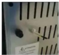
ALAR COOL FIRE - No electrical supply alarm
The lack of electrical supply during the work, stops the functioning of electrical components of the stove. When the electrical supply is restored the stove shows the alarm “ALAR COOL FIRE” and it is necessary to switch on again, after waiting for a cooling period, COOL FIRE, till when the smoke temperature goes below the limit temperature set at parameter Pr13.
ALAR FAN FAIL - Damage exhaust blower alarm
In case the exhaust blower (smoke fan) gets broken, the stove switches off and it is displayed the message ALAR FAN FAIL.
05.2 ELECTRONICS WITH 6-BUTTON LCD DISPLAY (Pellet stoves)
p. 42 F-2 F-3
PROPER FUNCTIONING AND CONTROL ADJUSTMENT DEVICES
Control panel
The control panel shows the information concerning the stove status. Several types of data can be displayed and the settings available according to the access level can be modified by entering the menu.
Depending on the selected mode and on their position on the display, the data visualised may acquire different meanings.
DESCRIPTION OF PANEL
P. 42 F-2
(A1) TIME CLOCK
(A2) ROOM TEMPERATURE
(A3) STATUS p. 42 F-2 and p. 58 figure 1
(A4) DIALOGUE
(A5) HEAT OUTPUT (A5)
Figure 1 p. 58 describes the meaning of the status indicators appearing on the display left side.
Programming: When the LED is lighted, it means that the corresponding component is active p. 58 figure 1
P. 42 F-3 describes the position of the messages visualised during working parameter programming or setting phase.
-
The input (B1) area shows the entered programming values
-
The menu level (B2) area displays the current menu. See chapter dedicated to menu p. 58.
BUTTON (P1) - Temperature increase:
When in programming mode, use this button to modify/increase the selected menu value. When in WORK/OFF, use instead this button to increase the room thermostat temperature value.
BUTTON (P2) - Temperature decrease:
When in programming mode, use this button to modify/decrease the selected menu value. When in WORK/OFF, use instead this button to decrease the room thermostat temperature value.
BUTTON (P3) - Set/menu:
Use this button to access temperature setting and user and technician parameter menu. After entering the menu, use this button to access the next sub-menu or set the value and move to the next menu item when in programming mode.
BUTTON (P4) - ON/OFF Unlocking:
Hold this button down for two seconds to manually switch the stove on or off respectively depending on its initial status (OFF or START).
Should have any alarm blocked the stove, press this button to unlock it and subsequently switch it off. After entering the menu or during the programming phase, use this button to access the lower menu level. Any change is automatically saved
BUTTON (P5) - Heat output decrease:
When in (WORK) mode, use this button to decrease the heat output value. In menu mode, use this button to move to the next menu item or, in programming mode, to go back to the subsequent sub-menu item. Any change is automatically saved.
BUTTON (P6) - Heat output increase:
When in (WORK) mode, use this button to modify the exchanger speed. In menu mode, use this button to go back to the previous menu item or, in programming mode, to go back to the previous sub-menu item. Any change is automatically saved.
THE MENU
Press P3 (MENU) button to access the menu.
It includes several items and levels to access settings and control board programming.
The menu items providing access to the technical setting are protected by access code.
BACKGROUND BURNER FOR PELLET
BACKGROUND BURNER FOR WALNUT SHELL
Important: do not inter change the two different bottom of the burner
- Choise of the kind of fuel from the main menù.
- Kind of fuel 1 = PELLET (CARICO PELLET)
- Kind of fuel 2 = NOCCIOLINO (CARICO NOCCIOLINO)
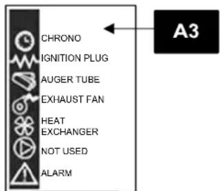
text_image
CHRONO IGNITION PLUG AUGER TUBE EXHAUST FAN HEAT EXCHANGER NOT USED ALARM A3Figure 1
Menu M2 – SELECT FUEL
This setting may reserve the fuel type (NOCCIOLINO or PELLET)
Menu M3 - SET CLOCK
Use this function to set current time and date. The control board is equipped with a lithium battery guaranteeing the internal time clock a 3/5 year-long life.
Menu M4 – SET CHRONO
Submenu M4 - 1 ENABLE CHRONO
The programmable thermostat functions can be disabled and enabled.
Submenu M4 - 2 PROGRAM DAY
The daily programmable thermostat functions can be enabled, disabled and set.
It is possible to set two on/off times defined by the times set according to the table below. If the value is set to OFF, the time clock ignores the control.
| Selection Meaning Available values | |
| START 1 switching-on time time - OFF | |
| STOP 1 switching-off time time - OFF | |
| START 2 switching-on time time - OFF | |
| STOP 2 switching-off time time - OFF |
Submenu M4 - 3 PROGRAM WEEK
The weekly programmable thermostat functions can be enabled, disabled and set.
The weekly programmer consists of 4 independent programmes which can be combined together in different ways.
The weekly programmer can be enabled or disabled.
Moreover, if the time is set to OFF, the time clock ignores the corresponding control.
N.B.: set the programming carefully in order to avoid overlapping of switching on and/or off times of different programmes on the same day.
Submenu M4 - 4 PROGRAM WEEK-END
The programmable thermostat functions can be enabled, disabled and set for the week-end (days 6 and 7, or Saturday and Sunday).
TIP: if you still do not know exactly the result you want to obtain, enable only one programme at a time to avoid confusion and unwanted stove switching on and off.
Disable the daily programme (PROGRAM DAY) if you want to use the weekly programme. If you use the weekly programme (PROGRAM WEEK-END) for 1, 2, 3 and 4 programmes, never enable the week-end programme. Always disable the weekly programme (PROGRAM WEEK) before enabling the week-end programme (PROGRAM WEEK-END).
Menu M5 – SELECT LANGUAGE
Use this function to select one of the languages available.
Menu M6 - MODE STAND-BY
If you select the "MODE STAND-BY" mode, the stove switches off after a period, set by Pr44, during which the room temperature remained at a value higher than the
SET temperature.
Only if the following condition occurs - TSET < (Tambiente - Pr43), it is then possible to switch the stove back on.
Set it to "OFF" to disable the buzzer
Menu M8 - LOAD INITIAL
Use this function to load pellets for a period of 90 seconds when the stove is switched off and cold. Press P1 button to start and P4 button to stop.
Menu M9 - STATE STOVE
This function displays the current status of all the devices connected to the stove. A few examples are included in the following pages.
Menu M10 – SETTINGS TECHNIC
This menu item is reserved to the stove installer. After entering the password, P1 (increase) and P2 (decrease) buttons allow all the stove working parameters to be set (KEY ACCESS).
USER FUNCTIONS
Standard functioning of a control board properly installed on a forced air pellet stove is described below with reference to the functions available to users. The indications listed below refer to a control board fitted with programmable thermostat.
Stove switching on
Hold down P4 for a few seconds to switch on the stove. The display shows the message when the stove is on (START).
Start-up phase
The stove performs all the steps of the start-up phase according to the parameters concerning its levels and times.
Ignition failure
The alarm is triggered when, after the period of time set by Pr01, the fume temperature has not reached the minimum value admitted (Pr13 parameter) with a gradient equal to 2^ C/min (NO LIGHTIN-).
Working mode
At the end of the start-up phase, if no problems occurred, the stove enters its normal (WORK) mode.
Exchangers are enabled if the fume temperature is higher than Pr15.
Changing set room temperature
Press P1 and P2 buttons to change the room temperature. The display shows the current SET temperature.
External thermostat/programmable thermostat
If you want to use an external programmable thermostat, connect it to the TERM clamps (connector CN7 pin 7-8).
• external thermostat: set the stove SET temperature to 7°C.
• external programmable thermostat: set the stove SET temperature to 7°C and disable (OFF) the chrono functions from 04-01 menu.
The stove external thermostat is enabled when the contact is closed with stove on.
Room temperature reaches set value (SET temperature)
When the set room temperature value is reached, the stove heat output is set automatically to the minimum value (MODULAT).
If the stove is in the (MODE STAND-BY) mode, it switches off after the period of time set by Pr44 and after reaching the SET temperature. If the following condition occurs - Tambiente > (TSET + Pr43), it is then possible to switch the stove back on.
Burn pot cleaning
When the stove is in the (WORK) mode, the (CLEANING FRE-POT) mode is activated for the period set by Pr12 parameter at the intervals set by Pr03 parameter.
Stove switching off
Hold down P4 button for approx. 2 seconds to switch off the stove. The Auger tube stops immediately and the exhaust blower reaches its maximum speed value. The (CLEANING FINAL) phase is performed.
At the end of the period of time set by Pr39, when the fume temperature has reached a value below Pr13 parameter, the exhaust blower stops.
Switching on the stove again
It will be possible to switch the stove back on only at the end of the safety period of time set by Pr38 and if the fume temperature has reached a value below Pr13. WHAT HAPPENS IN CASE OF....
Pellet ignition failure
If pellets do not ignite, the display shows the alarm message (NO LIGHTIN-).
Power outage (BLACK-OUT)
When the power is resumed after an outage, the stove enters the (CLEANING FINAL) phase and waits until the fume temperature reaches a value below Pr13.
If the power outage duration (BLACK-OUT) is longer than T, the stove switches off.
ALARMS
In case of malfunctioning the control board reports the problem and activates various procedures depending on the type of alarm. In case of alarm, the stove is always immediately switched off. The alarm status is reached after a set period of time Pr11 and can be cleared by pressing the P4 button.
ALARM ACTIVE ALARM FLOW – Abstract alarm
It occurs when the same sensor, which signals the alarm, is dirty, or the chimney is blocked.
ALARM ACTIVE PROBE EXHAUST - Fume temperature sensor alarm
The alarm is triggered when the fume temperature sensor is not working properly or is disconnected. During the alarm, the stove switches off.
ALARM ACTIVE HOT EXHAUST - Fume overtemperature alarm
Is triggered whenever the fume sensor detects a temperature exceeding 220°C.
The stove switching-off phase starts immediately.
ALARM ACTIVE NO LIGHTIN - Ignition failure alarm
The alarm is triggered whenever ignition fails. The stove switching-off phase starts immediately.
ALARM ACTIVE NO PELLET - Stove switching-off during working mode alarm
If during normal working mode, the flame goes out and the fume temperature falls below the minimum threshold (Pr13 parameter).
The stove switching-off phase starts immediately.
ALARM ACTIVE FAILURE DEPRESS - Auger tube safety pressure switch alarm.
If the pressure switch (meter pressure) detects a value higher the trigger threshold, it immediately switches off the Auger tube (to which it is connected in series) while the control board acquires this change in status through the AL2 clamp in CN4. The message "FAILURE DEPRESS" appears on the display and the stove is immediately switched off.
ALARM ACTIVE WAIT COOLING - Power outage
ALARM ACTIVE SAFETY THERMAL - General thermostat alarm
If the general safety thermostat detects a value exceeding the trigger threshold, it immediately switches off the Auger tube (to which it is connected in series), while the control board acquires this change in status through the AL1 clamp in CN4. The message SAFETY THERMAL is displayed and the system shuts down. Unscrew the black cap behind the stove and press the button to reset the contact.
ALARM ACTIVE FAN FAILURE - Damage exhaust blower alarm
Whenever the exhaust blower stops working properly, the stove switches off immediately and the message FAN FAILURE. The stove switching off phase starts immediately.
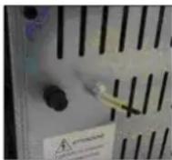
05.3 ELECTRONICS WITH 3 BUTTON DISPLAY N.100
(Pellet stoves – Pellet stove with oven – Pellet kitchen – Pellet kitchen with oven)
p. 42 F-4
PROPER FUNCTIONING AND CONTROL ADJUSTMENT DEVICES
Console
The control board can be managed by simply pressing a few buttons on the control panel. A display and the LED indicators inform about the stove operational status. When in programming mode all the parameters that can be modified using the buttons are shown on the display.
DESCRIPTION OF PANEL
LED (L0) Room temperature setting
LED (L1) Heat output setting
LED (L2) Chrono
LED (L3) ON/OFF
LED (L4) Alarm
LED (L5) Auger tube/exchanger / ignition plug
BUTTON (P1) decrease / menu / room temperature setting
BUTTON (P2) increase / stove status/heat output setting
BUTTON (P3) ON/OFF exit/confirm
DISPLAY (D1) status/heat output/parameter
THE MENU
Hold P1 button down to access the menu. It includes several items and levels to access settings and control board programming.
Menu M1 - SET CLOCK
Push and hold the (P1) button until you see the M1 writing, confirm with the ON/OFF (P3) button. With the (P1) and (P2) buttons change the current day and push the power button, set the hour and push ON/OFF (P3), set the minutes and push ON/OFF (P3), set the current day in number and push ON/OFF (P3), set the current month and push ON/OFF (P3), set the current year and at this point to confirm and exit push and hold the ON/OFF (P3) button until you see the current hour.
Menu M2 – SET CHRONO
Submenu M2 - 1 CHRONO ENABLE
Push and hold the (P1) button until you see the M1 writing, push the (P2) button until M2, confirm with ON/OFF (P3) and you will see the Menu M2-1, confirm with ON/OFF (P3) and with the arrow (P1) put ON to activate the general chrono; go back by holding down the ON / OFF (P3) button, and with (P2) choose the program to be activated.
Submenu M2 - 2 PROGRAM DAY
Two ON-OFF cycles fixed for every day
Submenu M2 - 3 PROGRAM UEEK
Four ON-OFF cycles and for every schedule you must select the days
Submenu M2 - 4 PROGRAM U-END
Two ON-OFF cycles for Saturday and Sunday
Selecting a program
Enter the desired program by pressing once ON / OFF (P3), the first parameter is the enabling of the program; set it to ON by pressing the button (P2) ATTENTION, ENABLE A PROGRAM AT A TIME TO AVOID PROBLEMS AT THE CHRONO). Press ON / OFF (P3), to set the starting time, and with the keys (P1) and (P2) to set the hour for the desired start, then press SET (P3) to set the stopping time, and with the arrows (P1) and (P2) set the stop time, only in the weekly program at this point press SET to confirm the days, and with the ON / OFF button move between the days of the week and with the keys (P1) and (P2) select ON or OFF. When you set the hours and days to confirm and exit the CHRONO hold the ON-OFF button down to the home screen: if you have properly set up the time schedules a green LED next to the clock on the top left of the display will light.
Menu M3 - LANGUAGE
Use this function to select one of the languages available. Press P2 (increase) and P1 (decrease) buttons to scroll through the options and press P3 button to confirm.
Menu M4 - STAND-BY
Use this function to enable or disable the STAND-BY mode. Press P3 button to select menu M4 and then P1 (decrease) or P2 (increase) button to select the ON or OFF status. Refer to the section concerning the stand-by mode for more details on its functioning.
Menu M5 - BUZZER
Use this function to enable or disable the control board buzzer during alarms. Press P1 or P2 button to enable or disable this function and P3 button to confirm.
Menu M6 - LOAD INITIAL
This function is only available when the stove is switched OFF. It allows the auger tube to be loaded upon the first stove start-up when the pellet hopper is empty. After selecting menu M6, the message "Pressure inc" will scroll on the display. Then press P2 (increase). The exhaust blower switches on at the maximum speed and the auger tube (auger tube LED on) starts working. They will switch off once the period of time indicated on the display has elapsed or after pressing P3 button.
Menu M7 - STATE STOVE
After entering menu M7 by pressing P3 button, the status of a few parameters with stove in working mode scrolls on the display. The table below contains an example of the values scrolling on the display together with their meaning.
| Displayed status - meaning | ||||
| 3.1" - Auger tube pellet feeding status | 52' - Time out | Toff - Thermostat status | 106° - Fume temperature | 1490 - Exhaust blower speed |
This menu item is reserved to the stove installer. After entering the password, P1 (decrease) and P2 (increase) buttons allow all the stove working parameters to be set.
Menu M9 - ESCAPE
Select this item by pressing the P3 button to exit the menu and to go back to the previous status.
USER FUNCTIONS
Standard functioning of a control board properly installed on an air stove is described below with reference to the functions available to users.
Stove ignition
First connect the stove plug to the mains and load the pellet hopper.
Be careful not to empty the entire bag at once. Perform this operation slowly.
The combustion chamber and the burn pot must be cleaned, removing any combustion residue. Verify that the hopper lid and the door are closed. Failure to do so could cause a malfunction of the stove and subsequent related alarms. Upon initial start-up ensure that in the burn pot there are no components that will burn (feet bag, instructions, etc.).
Hold P3 button down for a few seconds to switch on the stove. The message "START" appears on the display and the ON/OFF LED starts flashing if the stove has successfully switched on. This phase lasts for the period of time set by Pr01 parameter.
During this phase the stove goes into the pre-heating status: the ignition plug (as indicated by the relevant LED) and the exhaust blower switch on.
Any problem detected during the switching-on phase is indicated on the display and the stove goes into the alarm status.
Pellet feeding
The pellet feeding phase starts after approx. 1 minute: the message "LOAD PELLET" scrolls on the display and the ON/OFF LED starts flashing.
During the first stage the Auger tube feeds the pellets to the burn pot during a period of time set by Pr40 parameter (Auger tube LED on), the exhaust blower speed is set by Pr42 parameter and the ignition plug is still on (ignition plug LED on).
During the second stage, once the period of time set by Pr40 parameter has elapsed, the auger tube switches off (auger tube LED off) during a period of time set by Pr41 parameter, while the exhaust blower speed remains as in the previous status.
In case of ignition failure at the end of this phase, the auger tube switches back and remains on during the period of time set by Pr04 parameter, the exhaust blower speed is set by Pr16 parameter and the ignition plug is still on.
Fire on
Once fume temperature has reached and exceeded Pr13 parameter value, the stove goes into the ignition mode: the message "FLAME LIGHT" appears on the display and the ON/OFF LED starts flashing.
During this phase the temperature remains stable for a period of time preset by Pr02 parameter.
The exhaust blower speed is set by Pr17 parameter, the Auger tube remains on for a period of time set by Pr05 parameter (Auger tube LED flashing) and the ignition plug is off (ignition plug LED off).
Any problem during this phase will cause the control board to stop and the stove to go into error state.
Working mode
Once fume temperature has reached and exceeded Pr13 parameter value, maintaining it for the period of time set by Pr02 parameter, the stove enters the normal working mode. The message "UORK" appears on the display and the ON/OFF LED is on. Hold P2 button down to set the heat output and press P1 button to set the room temperature.
If fume temperature reaches the threshold set by Pr15 parameter, the air exchanger fan will switch on (as the exchanger LED).
IMPORTANT: During this phase, after a period of time set by PR03 parameter, the stove cleans the burn pot. The message "CLEANING FIRE-POT" scrolls on the display, the Auger tube is on (as the relevant LED) at a speed set by Pr09 parameter and the exhaust blower at a speed set by Pr08 parameter.
Once the period of time set by Pr12 parameter has elapsed, the stove goes back to the working mode. (this procedure does not concern the 4 KW stoves)
4 KW STOVES only
This type of stove switches off automatically every 8 hours of continuous or staggered operation, regardless of the CRONO SET settings, daily, weekly, and weekend programming. Switching off is done to clean the brazier, the display will show the message (CLEAN BRAZIER) and after a manual cleaning, the stove can be turned on again. The internal timer will automatically reset until you reach another 8 hours of operation.
Changing set heat output
During stove normal operation (UORK), the heat output can be changed by using P2 button (Heat output setting LED on).
Press P2 button again to increase the heat output and P1 button to decrease it. The display will show the set heat output.
Do not press any button for 5 seconds or press P3 button to exit the setting mode.
Only for the PELLET KITCHEN
The powers are regulated as it follows:
PTN1, PTN2, PTN3, PTN4, PTN5: powers with ventilation.
PT-1, PT-2, PT-3, PT-4, PT-5: powers without ventilation.
During summer if you have to cook or use the kitchen for any reason, you can use the powers PT- so that ventilation is not going to heat up the room.
Changing set room temperature
Press P1 button to change the set room temperature.
The display shows the set room temperature (SET temperature value). Press P1 and P2 buttons to decrease or increase, respectively, the temperature value. The value is saved after approx. 5 seconds and the display goes back to normal. Otherwise, press P3 to exit.
Room temperature reaches set value (SET temperature value)
Once the set room temperature value has been reached, the stove heat output is automatically set to the minimum value. During this phase the display shows the message "MODULAT-". If room temperature falls below the set value (Set temperature value), the stove will go back to the "UORK" mode and to the previously set heat output (Set heat output value).
Stand-by
When enabled in the menu, the STAND-BY function allows the stove to be switched off after complying with the following conditions.
It is enabled if the room temperature exceeds the relevant set value (Set room temperature value) during the period of time set by Pr44 parameter to which Pr43 parameter must be added. The message "GO-STBY" appears on the display followed by the minutes left. At the end of the period of time set by Pr44 parameter the message "UAIT COOLING" will appear on the display. During this phase the Auger tube is off (Auger tube LED off), the exchanger switches off once the threshold set by Pr15 parameter has been reached and the ON/OFF LED flashes. When fume temperature reaches the threshold set by Pr13 parameter, the stove goes into the STAND-BY mode and the message "STOP ECO TEMP GOOD" scrolls on the display. The Auger tube (Auger tube LED off), the exchanger (exchanger LED off) and the exhaust blower are off. If room temperature falls below the set value (Set room temperature value) plus the threshold set by Pr43 parameter, the stove switches back on.
Stove switching off
Hold P3 button down to switch off the stove. The display shows the message "CLEANING FINAL". The Auger tube motor switches off (Auger tube LED off), the exhaust blower speed is set by Pr08 parameter and the ON/OFF LED flashes. The exchanger blower remains on (exchanger LED on) until the fume temperature falls below the value set by Pr15 parameter. If, at the end of the period of time set by Pr39 parameter, the fume temperature remains below the threshold set by Pr10 parameter, the stove will switch off and the message "Off" appears on the display.
ALARMS
Should any malfunctioning be detected, the control board reports the problem in question: the alarm LED switches on (alarm LED on) and the buzzer goes off. In case of alarm, the stove is always immediately switched off
EXCEPT FOR THE POWER OUTAGE ALARM, the alarm status is reached at the end of the period of time set by Pr11 parameter and can be cleared by holding P3 button down. Whenever an alarm is cleared, the stove starts a switching-off phase for safety reasons. The alarm LED (alarm LED on) will remain on and the buzzer, if enabled, will sound intermittently during the entire alarm phase. Should the alarm not be cleared, the stove will in any case be switched off and the alarm message will remain on the display.
AL1 BLAC-OUT - Power outage alarm
Power outage may occur with stove in working mode. When power resumes, if the power outage period has been lower than the value set by a 20" parameter, the stove will restart in the WORKING mode. Otherwise the relevant alarm will be triggered. The message "AI1 BLAC-OUT" (scrolls on the display and the stove switches off.
AL2 PROBE EXHAUST - Fume temperature sensor alarm
The alarm is triggered in case of faulty fume sensor. The stove goes into the alarm status and the alarm LED switches on (alarm LED on). The message "AL2 PROBE EXHAUST" will scroll on the display and the stove will switch off.
AL3 HOT EXHAUST - Fume overheating alarm
The alarm is triggered whenever the fume sensor detects a temperature higher than a fixed set value, which may not be modified by means of a parameter. The message "AL3 HOT EXHAUST" appears on the display and the stove switches off.
AL4 FAN FAILURE - Faulty fume encoder alarm
The alarm is triggered in case of exhaust blower failure. The stove goes into the alarm status and the message "AL4 FAN FAILURE" will scroll on the display.
AL5 NO LIGHTIN- - Ignition failure alarm
The alarm is triggered in case of ignition phase failure. This occurs when fume temperature does not exceed the value set by Pr1 3 parameter at the end of the period of time set by PR0 1 parameter. The message "AL5 NO LIGHTIN-" scrolls on the display and the stove goes into the alarm status.
AL6 NO PELLET - No pellet alarm
The alarm is triggered when fume temperature falls below the value set by Pr13 parameter with stove in working mode. The message "AL6 NO PELLET" scrolls on the display and the stove goes into the alarm status.
AL7 SAFETY THERMAL - Thermal safety overheating alarm
The alarm is triggered whenever the general safety thermostat detects a temperature exceeding the trigger threshold. The thermostat switches off the Auger tube, being connected in series to its power supply, the control board reports the alarm status (alarm LED on) by showing the message "AL7 SAFETY THERMAL" on the display and the stove switches off.
AL8 FAILURE DEPRESS - No negative pressure alarm
The alarm is triggered whenever the external pressure switch detects a pressure higher value below the trigger threshold. The pressure switch switches off the Auger tube, being connected in series to each other, and the control board reports the alarm status (alarm LED on) by showing the message "AL8 FAILURE DEPRESS" on the display. The stove switches off.
05.4 ELECTRONICS WITH 6 BUTTON LED DISPLAY N. 100
(Pellet stoves - Pellet inserts)
p. 42 F-1
PROPER FUNCTIONING AND CONTROL ADJUSTMENT DEVICES
Console
The control board can be managed by simply pressing a few buttons on the control panel. A display and the LED indicators inform about the stove operational status. When in programming mode all the parameters that can be modified using the buttons are shown on the display.
DESCRIPTION OF PANEL
Button (P1) Room temperature increase
Button (P2) Room temperature decrease
Button (P3) Set / menu
Button (P4) ON / OFF
Button (P5) Heat output decrease
Button (P6) Heat output increase
Display (D1):
It displays the detected room temperate and the time at start-up.
During working mode, it shows the heat output set by the user.
When modifying user/technician parameters, it shows the value of the parameter in question.
Led (L1) Chrono enabled - CHRONO
Led (L2) Auger tube moving – AUGER TUBE ON
Led (L3) Remote control receiver - REMOTE CONTROL
Led (L4) Thermostat on - ROOM TEMP SETTING
Led (L5) Flashing during temperature setup or when inside menus - SET
Display (D2):
It shows the board status during start-up phase.
During working mode, it shows the temperature set by the user.
When modifying user/technician parameters, it shows the label of the parameter in question.
MENU
Press P3 button to access the menu. It includes several items and levels to access settings and control board programming.
Menu M1 - SET CLOCK
Press the SET button (P3) once, i twill appear the menu M1 SET CLOCK, confirm by pressing SET (P3) once; with the arrows on the left SET(P3) the current day and press SET (P3); SET (P3) the current time and press SET (P3); SET (P3) the minutes and then push SET (P3); SET (P3) the current day in number and press SET (P3); SET (P3) the current month in number and press SET (P3); SET (P3) the current year in number, and at this point to confirm and exit the menu M1 press once the power button.
Menu M2 – SET CHRONO
Submenu M2 - 1 CHRONO ENABLE
Press once the SET (P3) button and with arrow (P5) go to M2, enter the menu by pressing once SET (P3) so it appears the menu M2-1, confirm with SET (P3) and with arrow (P1) put ON to activate the general chrono. To go back please press the button ON-OFF (P4), and with arrow (P5) select the program to be activated.
Submenu M2 - 2 PROGRAM DAY
Two ON-OFF (P4) cycles fixed for each day.
Submenu M2 - 3 PROGRAM UEKK
Four ON-OFF (P4) cycles and every time must be selected daily.
Submenu M2 - 4 PROGRAM U-END
Two ON-OFF (P4) cycles for Saturday and Sunday.
To set a program:
Enter the desired program by pressing the SET (P3) button once and the first parameter is the enabling, put it in ON by pressing the arrow (P1) (ATTENTION: ENABLE ONE PROGRAM AT A TIME TO AVOID PROBLEM). Press SET (P3) to SET (P3) the start's hour, with arrows (P1) and (P2) SET (P3) the hour of the ignition and press SET (P3) to SET (P3) the stop hour. With arrows (P1) and (P2) SET (P3) the hour of the off. Then only in the weekly program this point you must confirm by pressing SET (P3) the days, with arrows (P5) and (P6) move between the days of the week and with arrow (P1) put ON or OFF. When you SET (P3) the times and days to confirm and exit the chrono press the ON-OFF (P4) button up to the home screen, if you have set the times correctly i twill light the green LED, which is close to an hourglass in the left part of the upper display.
Menu M3 - LANGUAGE
Use this function to select one of the languages available. Press P1 (increase) and P2 (decrease) buttons to scroll through the options and press P4 button to confirm.
Menu M4 - STAND-BY
Use it to enable or disable the Stand-by mode. Press P3 button to select menu M4 and then P1 or P2 to select the ON or OFF status. Refer to the section concerning the stand-by mode for more details on its functioning.
Menu M5 - LOAD INITIAL
This function is only available when the stove is switched OFF. It allows the auger tube to be loaded upon the first stove start-up when the pellet hopper is empty. After selecting menu M5, the message "P1 TO LOAD" will scroll on the display. Then press P1 (increase). The exhaust blower switches on at the maximum speed and the auger tube (auger tube LED on) starts working. They will switch off once the period of time indicated on the display has elapsed or after pressing P4 button.
Menu M6 – STATE STOVE
After entering menu M6 by pressing P3 button, the status of a few parameters with stove in working mode scrolls on the display. The table below contains an example of the values scrolling on the display together with their meaning.
| Displayed status - meaning | ||||
| 3.1" - Auger tube pellet feeding status | 52' - Time out | Toff - Thermostat status | 106° - Fume temperature | 1490 - Exhaust blower speed |
Menu M7 - SET TECHNIC
This menu item is reserved to the stove installer. After entering the password, P1 (increase) and P2 (decrease) buttons allow all the stove working parameters to be set.
USER FUNCTIONS
Standard functioning of a control board properly installed on an air stove is described below with reference to the functions available to users.
Stove ignition
Hold P4 button down for a few seconds to switch on the stove. The display shows the message "START" when the stove is on.
During this phase the stove goes into the pre-heating status: the ignition plug (as indicated by the relevant LED) and the exhaust blower switch on.
Any problem detected during the switching-on phase is indicated on the display and the stove goes into the alarm status.
Pellet feeding
The pellet feeding phase starts after approx. 1 minute: the message "LOAD PELLET" scrolls on the display. During the first stage the auger tube feeds the pellets to the burn pot for a fixed period of time. During the second stage the auger tube switches off (auger tube LED off), while the exhaust blower speed and the ignition plug remain as in the previous status. In case of ignition failure at the end of this phase, the auger tube and the ignition plug remain on.
Fire present
Once fume temperature has reached and exceeded a pre-set threshold, the stove goes into the ignition mode and the message "FLAME LIGHT" appears on the display.
The exhaust blower speed is fixed, the auger tube remains on for a determined period of time (auger tube LED flashing) and the ignition plug is off (ignition plug LED off). Any problem during this phase will cause the control board to stop and the stove to go into error state.
Stove operational
Once fume temperature has reached a given value, maintaining it for a pre-set period of time, the stove enters the normal working mode. The upper display shows the time and room temperature, while the lower display shows the heat output set and the actual heat output of the stove. Press buttons P5 and P6 to set the heat output and buttons P1 and P2 to set the room temperature. If fume temperature reaches the threshold set, the air exchanger fan will switch on.
During this phase, the stove performs a cleaning of the burn pot. The message “CLEAN BRAZIER” scrolls on the display, the Auger tube is on (as the relevant LED) and the exhaust blower is on. Once the set period of time has elapsed, the stove goes back to the working mode.
Changing set heat output
During stove normal operation (working mode), the heat output can be changed by using the P5, P6 buttons. Press P6 button again to increase the heat output and P5 button to decrease it. The display will show the set heat output. Do not press any button for 5 seconds or press P4 button to exit the setting mode.
Changing set room temperature
Press P1 and P2 buttons to change the room temperature. The display shows the set room temperature (SET temperature value). Press P1 and P2 buttons to increase or decrease, respectively, the temperature value. The value is saved after approx. 5 seconds and the display goes back to normal. Otherwise, press P4 to exit. You can also set "Man"; the stove will operate in "MAN" manual mode, at a fixed heat output. Or t-e, if you connected an external thermostat.
Room temperature reaches set value (SET temperature value)
When the set room temperature value is reached, the stove heat output is automatically set to the minimum value. During this phase the display shows the message "MODULAT-". If room temperature falls below the set value (Set temperature value), the stove will go back to "Working" mode and to the previously set heat output (Set heat output value). If there is an external thermostat and the room temperature has been set to t-e, if the thermostat is open it will begin modulation and if closed, it will return to the heat output set.
Stand-by
When enabled in the menu, the STAND-BY function allows the stove to be switched off after complying with the following conditions. It is enabled if the room temperature exceeds the relevant set value (Set room temperature value) plus a pre-set temperature delta for a certain period of time. The message "SO-STBY" appears on the display followed by the minutes left. At the end of the period of time set, the message (ATTESA RAFFRED-) "Wait for cooling" will appear on the display. During this phase the auger tube is off (Auger tube LED off) and the exchanger switches off. When fume temperature reaches the relevant threshold, the stove goes into the Stand-by mode and the message "STOP ECO TEMP OK" scrolls on the display. The Auger tube (Auger tube LED off), the exchanger (exchanger LED off) and the exhaust blower are off.
If room temperature falls below the set value (Set room temperature value) plus the threshold set by the temperature delta, the stove switches back on.
Stove switch off
Hold P4 button down to switch off the stove. The display shows the message (CLEANING FINAL). The Auger tube motor stops (Auger tube LED off) and the exhaust blower speed is pre-set. The fan of the exchanger (exchanger LED on) remains active until the fume temperature falls below the pre-set value. After a given time, if the fume temperature is below the given threshold, the stove switches off, displaying the message "Off".
ALARMS
Should any malfunctioning be detected, the control board reports the problem in question: the alarm LED switches on (alarm LED on) and the buzzer goes off. In case of alarm, the stove is always immediately switched off
EXCEPT FOR THE POWER OUTAGE ALARM, the alarm status is reached after a given time and can be cleared by holding P4 button down. Whenever an alarm is cleared, the stove starts a switching-off phase for safety reasons. The alarm LED (alarm LED on) will remain on and the buzzer, if enabled, will sound intermittently during the entire alarm phase. Should the alarm not be cleared, the stove will in any case be switched off and the alarm message will remain on the display.
AL1 BLAC-OUT - Power outage alarm
Power outage may occur with stove in working mode. When power resumes, if the power outage period has been lower than the value set by a 20 second parameter, the stove will restart in the WORKING mode. The message "AL1 BLAC-OUT" scrolls on the display and the stove switches off.
AL2 PROBE EXHAUST - Fume temperature sensor alarm
The alarm is triggered in case of faulty fume sensor. The stove goes into the alarm status and the alarm LED switches on (alarm LED on). The message "AL2 PROBE EXHAUST" will scroll on the display and the stove will switch off.
AL3 HOT EXHAUST - Fume overtemperature alarm
The alarm is triggered whenever the fume sensor detects a temperature higher than a fixed set value, which may not be modified by means of a parameter. The message "AL3 HOT EXHAUST" appears on the display and the stove switches off.
AL4 FAN FAILURE - Faulty fume encoder alarm
The alarm is triggered in case of exhaust blower failure. The stove goes into the alarm status and the message "AL4 FAN FAILURE" will scroll on the display.
AL5 NO LIGHTIN- - Ignition failure alarm
The alarm is triggered in case of ignition phase failure. This happens if after the relevant given time, the fume temperature does not exceed a given threshold. The message "AL5 NO LIGHTIN-" scrolls on the display and the stove goes into the alarm status.
AL6 NO FIRE - No pellet alarm
The alarm is triggered when fume temperature falls below a given parameter. The message "AL6 NO FIRE" scrolls on the display and the stove goes into the alarm status.
AL7 SAFETY THERMAL - Thermal safety overheating alarm
The alarm is triggered whenever the general safety thermostat detects a temperature exceeding the trigger threshold.
The thermostat switches off the Auger tube, being connected in series to its power supply, the control board reports the alarm status (alarm LED on) by showing the message "AL7 SAFETY THERMAL" on the display and the stove switches off.
AL8 FAILURE DEPRESS - No negative pressure alarm
The alarm is triggered whenever the external pressure switch detects a pressure higher value below the trigger threshold. The pressure switch switches off the Auger tube, being connected in series to each other, and the control board reports the alarm status (alarm LED on) by showing the message "AL8 FAILURE DEPRESS" on the display. The stove switches off.
05.5 ELECTRONICS WITH REMOTE CONTROL
(Pellet stoves)
p. 43 F-5
PROPER FUNCTIONING AND CONTROL ADJUSTMENT DEVICES
Control panel
The control panel shows the information concerning the stove status. Several types of data can be displayed and the settings available according to the access level can be modified by entering the menu.
Depending on the selected mode and on their position on the display, the data visualized may acquire different meanings.
PANEL DESCRIPTION
DISPLAY (P0)
BUTTON (P1) - Decrease:
When in programming mode, use this button to modify/decrease the selected menu value. When in WORK/OFF, use instead this button to decrease the room thermostat temperature value or stove heat output.
BUTTON (P2) - Increase:
When in programming mode, use this button to modify/increase the selected menu value. When in WORK/OFF, use instead this button to increase the room thermostat temperature value or the stove heat output.
BUTTON (P3) - ON/OFF Unlocking:
Hold this button down for two seconds to manually switch the stove on or off respectively depending on its initial status OFF or START.
Press it once to go back to the previous menu and up to the initial screen.
Should have any alarm blocked the stove, press this button to unlock the stove and subsequently switch it OFF.
BUTTON (P4) – Set Room Temperature value:
When in WORK mode, use this button to access the set room temperature value. In menu mode, use this button to go back to the previous menu item or, in programming mode, to go back to the previous sub-menu item. Any change is automatically saved.
BUTTON (P5) - Set Heat Output value:
When in WORK mode, use this button to access the heat output value. In menu mode, use this button to move to the next menu item, while, in programming mode, to move to the subsequent sub-menu item. Any change is automatically saved.
BUTTON (P6) – Return:
Serves to return to the previous menu.
BUTTON (P7) - Set/menu:
Use this button to access user and technician parameter menu. After entering the menu, use this button to access the next sub-menu level or set the value and move to the next menu item when in programming mode.
BUTTON (T1) ON/OFF button: to manually switch the stove on or off
BUTTON (T2) + button: heat output increase
BUTTON (T3) - button: heat output decrease
LED (L1) Signal LED: it confirms that signal has been received
LED (L2) Alarm LED: it indicates the stove alarm status. Clear using on/off button
MENU
Press P7 (MENU) button to access the menu.
It includes several items and levels to access settings and control board programming. The menu items providing access to the technical setting are protected by access code.
Menu M2 - SET CLOCK
Use this function to set current time and date. The control board is equipped with a lithium battery guaranteeing the internal time clock a 3/5 year-long life.
Menu M3 - SET CHRONO
Submenu M3 -1 ENABLE CHRONO
The programmable thermostat functions can be disabled and enabled.
Submenu M3 - 2 PROGRAM DAY
The daily programmable thermostat functions can be enabled, disabled and set
It is possible to set two on/off times defined by the times set according to the table below. If the value is set to OFF, the time clock ignores the control:
| setting meaning available values | |
| START 1 switchin on time time - OFF | |
| STOP 1 switching off time time - OFF | |
| START 2 switchin on time time - OFF | |
| STOP 2 switching off time time - OFF |
Submenu M3 - 3 PROGRAM WEEK
The weekly programmable thermostat functions can be enabled, disabled and set.
The weekly programmer consists of 4 independent programmes which can be combined together in different ways.
The weekly programmer can be enabled or disabled.
Moreover, if the time is set to OFF, the time clock ignores the corresponding control.
N.B.: set the programming carefully in order to avoid overlapping of switching on and/or off times of different programmes on the same day.
Submenu M3 - 4 PROGRAM WEEK-END
The programmable thermostat functions can be enabled, disabled and set for the week-end (days 6 and 7, or Saturday and Sunday).
TIP: if you still do not know exactly the result you want to obtain, enable only one programme at a time to avoid confusion and unwanted stove switching on and off. Disable the daily programme if you want to use the weekly programme. If you use the weekly programme for 1, 2, 3 and 4 programmes, never enable the week-end programme.
Always disable the weekly programme before enabling the week-end programme.
Menu M4 – SELECT LANGUAGE
Use this function to select one of the languages available.
Menu M5 – SELECT FEELER
Use this menu to select the internal or the remote control sensor
Menu M6 - MODO STAND-BY
If you select the "MODO STAND-BY" mode, the stove switches off after a period of time, set by Pr44, during which the room temperature remained at a value higher than the SET temperature.
Only if the following condition occurs - TSET < (Tambiente - Pr43), it is then possible to switch the stove back on.
Set it to "OFF" to disable the buzzer.
Menu M8 - LOAD INITIAL
Use this function to pre-load pellets for a period of 90 seconds when the stove is switched off and cold. Press P1 button to start and P3 button to stop. The initial load phase must be carried out 5-6 times in case of 12kW corner inserts. The initial load phase will be carried out also when the hopper gets completely empty during insert normal operation. The auger tube empties completely and the LOAD INITIAL phase must be repeated.
Menu M9 – STATE STOVE
This function displays the current status of all the devices connected to the stove. A few examples are included in the following pages.
Menu M10 – SETTINGS TECHNIC
This menu item is reserved to the stove installer. After entering the password, P2 (increase) and P1 (decrease) buttons allow all the stove working parameters to be set.
USER FUNCTIONS
Standard functioning of a control board properly installed on a forced air pellet stove is described below with reference to the functions available to users. The indications listed below refer to a control board fitted with programmable thermostat.
The technical setting mode is described in detail in the following sections.
Switch on the stove
To turn on the stove, turn on P3 for a few seconds. The ignition is signaled in the display
Start-up phase
The stove performs all the steps of the start-up phase according to the parameters concerning its levels and times.
Ignition failure
The alarm is triggered when, after the period of time set by Pr01, the fume temperature has not reached the minimum value admitted (Pr13 parameter) with a gradient equal to 2^ C/min.
Working mode
At the end of the start-up phase, if no problems occurred, the stove enters its normal WORK mode.
Exchangers are enabled if the fume temperature is higher than Pr15. Exchangers no.2 and 3 start working only if they were previously enabled.
Changing set room temperature
Press P1 and P2 buttons to change the room temperature. The display shows the current SET temperature value.
External thermostat/programmable thermostat
If you want to use an external programmable thermostat, connect it to the TERM clamps (connector CN7 pin 7-8).
• external thermostat: set the stove SET temperature to 7°C.
• external programmable thermostat: set the stove SET temperature to 7°C and disable the chrono functions from 03-01 menu.
The stove external thermostat is enabled when the contact is closed with stove on.
Room temperature reaches set value (SET temperature)
When the set room temperature value is reached or the fume temperature has reached the Pr13 value, the stove heat output is set automatically to the minimum value (MODULAT-) mode.
If the stove is in the MODE STAND-BY mode, it switches off after the period of time set by Pr44 and after reaching the SET temperature. If the following condition occurs - Tambiente > (TSET + Pr43), it is then possible to switch the stove back on.
Burn pot cleaning
When the stove is in the WORK mode, the "CLEANING FIRE-POT" mode is activated for the period set by Pr12 parameter at the intervals set by Pr03 parameter.
Stove switching off
Hold P3 button down for approx. 2 seconds to switch off the stove. The Auger tube stops immediately and the exhaust blower reaches its maximum speed value. The CLEANING FINAL phase is performed. At the end of the period of time set by Pr39, when the fume temperature has reached a value below Pr13 parameter, the exhaust blower stops.
Switching on the stove again
It will be possible to switch the stove back on only at the end of the safety period of time set by Pr38 and if the fume temperature has reached a value below Pr13.
WHAT HAPPENS IN CASE OF...
Pellet ignition failure
If pellets do not ignite, the display shows the alarm message "NO LIGHTIN-".
Power outage
When the power is resumed after an outage, the stove enters the CLEANING FINAL/BLACK OUT phase and waits until the fume temperature reaches a value below Pr13.
If the power outage duration is longer than T, the stove switches off.
ALARMS
In case of malfunctioning the control board reports the problem and activates various procedures depending on the type of alarm. Possible alarm messages are listed below.
In case of alarm, the stove is immediately switched off.
The alarm status is reached after a set period of time (Pr11) and can be cleared by pressing P3 button.
ALARM ACTIVE PROBE EXHAUST - Fume temperature sensor alarm
The alarm is triggered when the fume temperature sensor is not working properly or is disconnected. During the alarm, the stove switches off.
ALARM ACTIVE HOT EXHAUST - Fume overheating alarm
The alarm is triggered when the fume sensor registers a temperature exceeding 220°C. The stove switching-off phase starts immediately.
ALARM ACTIVE NO LIGHTIN- - Ignition failure alarm
The alarm is triggered whenever ignition fails. The stove switching-off phase starts immediately.
ALARM ACTIVE NO LIGHTIN- - Stove switching-off during working mode alarm
The alarm is triggered when, during normal working mode, the flame goes out and the fume temperature falls below the minimum threshold set by Pr13 parameter. The stove switching-off phase starts immediately.
ALARM ACTIVE CLEANING FINAL - Power outage
ALARM ACTIVE FAILURE DEPRESS - Auger tube safety pressure switch alarm
If the pressure switch (meter pressure) detects a value below the trigger threshold, it immediately switches off the Auger tube (to which it is connected in series) while the control board acquires this change in status through the AL2 clamp in CN4. The message "FAILURE DEPRESS" appears on the display and the stove is immediately switched off.
ALARM ACTIVE SAFETY THERMAL - General thermostat alarm
If the general safety thermostat detects a value exceeding the trigger threshold, it immediately switches off the Auger tube (to which it is connected in series), while the control board acquires this change in status through the AL1 clamp in CN4. The message "SAFETY THERMAL" appears on the display and the stove is immediately switched off. Unscrew the black cap on the back of the stove and press the button to reset the contact.
ALARM ACTIVE FAN FAILURE - Damaged exhaust blower alarm
Whenever the exhaust blower stops working properly, the stove switches off immediately and the message FAN FAILURE appears on the display. The stove switching off phase starts immediately.
CERCA CAMPO
This message appears when the remote control cannot connect to the emergency panel. Make sure that board is powered or that the emergency panel (receiver) is connected properly.
Transmission Unit Setup:
The stove must be connected to the main power supply. Press simultaneously the keys (P1) and (P2) for about 3-4 seconds until SCEGLI UNITA' appears and then select with the keys (P1) and (P2) the transmission unit (1-2-3 ...). The remote controls are supplied with transmission units set to 0 (default unit). Hold down the ON / OFF button (P3) for about 3 seconds to store. The remote control is ready for normal operation.
These operations must be carried out within 30 seconds of the stove feeding.
05.6 ELECTRONICS WITH REMOTE CONTROL LCD
(Air-tight stoves)
PROPER FUNCTIONING AND CONTROL ADJUSTMENT DEVICES
The remote control system replaces the classic display of the traditional pellet stoves. It comes with charger, rechargeable batteries, support and plugs with screws for wall mounting. It can also work with alkaline batteries.
Installing the remote control system on the stove:
- cut off the power supply to the stove.
- enable the power supply and press any free key on the handheld remote control (that is not associated with another stove within the operating field of the remote control) after the "beep".
Stand-by and recharge:
The remote control goes automatically into stand-by if not used for more than 30. "Press any key or simply move the remote control to wake up from stand-by. The handheld remote control has a battery life of about 3 days. After this period, it no longer responds and it is therefore necessary to recharge it using the battery charger supplied with the product; we recommend that you charge it for at least 60 minutes (the time necessary for reaching the minimum battery level that will allow the device to work properly). We generally recommend that you place it in the appropriate support when not using it. The functions assigned to the remote control will not be lost; not even if completely discharged.
In case of damage of the remote control you can operate the stove using the special emergency switch placed on the back of the stove.
Emergency switch:
In case the remote control does not work, you can turn on and off the stove with the button positioned on the rear of the stove near the power cord. (See image on p. 55 EMERGENCY SWITCH)
PANEL DESCRIPTION
Button (P1) Programmable thermostat access key.
Button (P2) On/off key.
Button (P3) Hold the P3 key to view useful information.
Button (P4) Press the P4 key until the ROOM TEMPERATURE menu
appears on the display and then change the value using the P5 and P6 keys.
Button (P5) Up key. You can also use it to scroll through the menus.
Button (P6) Down key. You can also use it to scroll through the menus.
Display (D1) current day and date.
Display (D2) current hour and minute.
Display (D3) room temperature.
Display (D4) stove status (OFF).
Display (D5) operating mode (NORMAL or PROGRAM).
Display (D6) the letter (A) next to it indicates if the room temperature is lower than the one set.
QUICK MENU
The P4 key (SET/MENU) allows you to open the menu functions. Press it for several times to browse through the pages below:
Maximum heat output setting (MAXIMUM POWER): Use the P5 and P6 keys to increase and respectively decrease the maximum heat output SET. Press P4 again to go to the next page.
ECO STOP: Use the P5 and P6 keys to switch between ON and OFF. The next P4 pressure moves to the next page. Enables or disables the ECO STOP mode. Room temperature setting (ROOM TEMPERATURE): Use the P5 and P6 keys to increase and respectively decrease room 1 SET temperature. Press P4 again to return to home page.
User menu
Open the main page and then hold the P4 key:
- EXIT: returns to main page.
- PRE LOADING: opens the pre-load function.
• SYSTEM STATUS: displays the page that contains information on the current status of the system. - PELLET SET: allows the user to adapt the functionality of the system to the quality of the pellets used.
- GENERAL SETTINGS: open the "general settings" submenu.
PRE LOADING: (available only when the stove is off). There are two pre-load methods available:
NORMAL: hold the P5 key (up) as long as you want the auger tube to work. Press P3 to exit.
AUTO: carries out a pre-load at a time set. Press P3 to exit.
System status: it displays in order: Pellet type settings correction table:
• the status of the stove
• the fume temperature in °C
- fume fan speed (if equipped with encoder) in rpm
• the current heat output level
• room temperature in °C
• auger tube motor speed
• exchanger fan speed expressed as a percent
- board temperature
- flow set
- flow measured
Use the P5, P6 keys to scroll through the pages. Press p4 to exit.
| setting fume exhaustion correction pellet load correction | |
| 0 10% increase 10% decrease | |
| 1 8% increase 8% decrease | |
| 2 6% increase 6% decrease | |
| 3 4% increase 4% decrease | |
| 4 2% increase 2% decrease | |
| 5 no correction no correction | |
| 6 2% decrease 2% increase | |
| 7 4% decrease 4% increase | |
| 8 6% decrease 6% increase | |
| 9 8% decrease 8% increase | |
| 10 10% decrease 10% increase | |
PELLET SET: Use the P5 and P6 keys to select the desired load settings and confirm by pressing P4.
GENERAL SETTINGS: the display shows in order:
- EXIT: returns to main page.
- TIME SETTING: open the time and date settings page. Switch between fields using the P4 (SET) key. Use the P5 and P6 keys to select the desired values. Note that, thanks to the system calendar, you do not need to set the day of the week. Press P4 to exit.
- PROBE ON RADIO (Y/N): enables the room temperature sensor placed inside the handheld remote control. Use the P5 and P6 buttons to enable/disable the room temperature sensor installed in the handheld remote control. Press P4 to exit. If the communication between the handheld remote control and the stove is lost, the stove will automatically take the standard room temperature sensor as reference.
- LANGUAGE SET: allows you to select the desired language.
• LOGS: it displays the events (alarms) log. - SERVICE: it displays information on the stove status.
- PELLET LEVEL: enables or disables the pellet level sensor.
- ECO-STOP HYS+: positive hysteresis of the room temperature sensor. E.G.: ECO-STOP HYS+ value = 1.0. The stove enters the ECO STOP mode when the room temperature exceeds the set room temperature by 1.0^ C.
- ECO-STOP HYS+:- negative hysteresis of the room temperature sensor. E.G.: ECO-STOP HYS+ value = 1.0. The stove resumes its operation once the room temperature drops below the set room temperature by 1.0 °C.
Programmable thermostat
The programmable thermostat function allows for the programming of the stove automatic switching on and off and of the SET temperature and SET heat output enabling during the week. To this purpose, you can either opt for the predefined settings or you can make your own ones. You can open the PROGRAMMER SET menu by holding the P1 key. From the programmable thermostat menu you can make all necessary settings for proper system operation.
Enabling the programmable thermostat
After finding the corresponding menu item, use the P4 (SET) key to open the selection menu. Use the P5 and P6 to enable/disable the option. Press P4 to save and exit. After enabling the programmable thermostat, you need to switch the stove on by holding the P2 key; it will enter the state previously defined by you for that particular period of time. If you enable the programmable thermostat when the stove is already running, it will enter the programmed state and level after half an hour. The stove will carry out the scheduled programme only if switched on. The programmable thermostat is automatically disabled if the stove enters an alarm condition to prevent the stove from switching on before removing the causes of the alarm. After removing the alarm causes, you will have to enable chrono (PROGRAM ENABLING) once again.
SET TIMES p. 43 F-7
Button (A1) HOURS
Button (A2) NO. ROOM
Button (A3) DAY
Button (A4) COPY
Button (A5) PASTE
Button (A6) EXIT
Button (A7) HEAT OUTPUT
LEVEL OF POWER p. 43 F-7
Livel (A7-a) OFF
Livel (A7-b) ECONOMY
Livel (A7-c) NORMAL
Livel (A7-d) COMFORT
Maximum heat output level setting
From this menu you can set 3 heat output levels: COMFORT SETTING, NORMAL SETTING, ECONOMY SETTING. To each of them is assigned a maximum heat output level. Each of them has a settings page.
The TIME SLOT SETTING page displays each day of the week, identified by the field (A3) DAY, each of them divided into 24-hour periods (0, 1, 2, ... 24). Each period is then divided into two half-hours highlighted in this example by the message (A1) HOURS.
Selecting the functions and the times.
Use the P5 and P6 to scroll through all the hours, days of the week and programming symbols (copy, paste, exit). Press the P4 (SET) key repeatedly until the notch reaches the desired height. Press the P4 key several times more to set the desired level (OFF, ECONOMY, NORMAL and COMFORT). Switch to other periods of time using the P5 and P6 keys.
Changing the day of the week.
Use the P5 and P6 keys to select the day of the week. Press P4 (SET) to change the day. All the days of the week are available for selection. After selecting the desired day, use the P5 and P6 buttons to select the desired period of time and make the desired settings as previously described. Please note that for each day of the week you can set a significant number of start-ups, shut-dows and temperature level changes.
To copy the settings made for one of the days of the week, proceed as follows:
• use the P5 (next) and P6 (back) keys to scroll through all periods of time until reaching the copy symbol; then, press P4 (SET).
- use the P6 (back) key to selected the day of the week and the P4 key to scroll through the days until reaching the day on which you want to paste the previously copied settings.
- press the P5 (next) key until reaching the paste symbol and then press the P4 (SET) key.
Carry out these operations for all the days in which you want to obtain similar results. To exit, use the P5 (next) and P6 (back) keys until you reach the exit symbol and then press P4 (SET).
Ignition
First connect the stove plug to the mains and load the pellet hopper.
Be careful not to empty the entire bag at once. Perform this operation slowly. The combustion chamber and the burn pot must be cleaned, removing any combustion residue. Verify that the hopper lid and the door are closed. Failure to do so could cause a malfunction of the stove and subsequent related alarms.
Upon initial start-up ensure that in the burn pot there are no components that will burn (feet bag, instructions, etc.).
Press the P2 key for about 2 seconds (ON/OFF). The following modes are activated in sequence:
- Mode CHECK, the system checks if the sensors are correctly installed and functional. If the flow control function is enabled, the system also check the flow rate sensor. If the calibration procedure has not been carried out, the system reports a relevant error condition.
- Mode (Initial warming), the ignition plug and the exhaust blower turn on.
- Mode PRE LOADING the exhaust blower and the auger tube run continuously.
- Mode Wait pellet loading is interrupted while the exhaust blower remains on together with the ignition plug to facilitate the ignition of the pellet. Fire on mode, the ignition plug is off and the system checks if the flame is stable enough to generate an increase in the fume temperature of at least 1.5°C/minute. If the abovementioned condition is met, the stove enters the heat output mode. Otherwise, the system enters the alarm condition due to lack of stability.
- Mode Ignition 1, the system switches to the next mode once the fume temperature reaches a set value. If this does not happen within the set time, the system repeats the mode without loading the pellets. If the conditions for passing to the next mode are still not met, the system enters the start-up failed alarm condition.
- Mode Ignition 2, the system switches to the next mode when the set temperature is exceeded. If this does not happen within the set time, the system enters the start-up failed alarm condition. After reaching the pre-set fume temperature, the blowers start.
- Mode Fire on. After correctly completing all these phases, the ignition plug switches off and the system checks whether the flame is stable enough to generate an increase in the fume temperature of at least 1.5^ C/min.
If the abovementioned condition is met, the stove enters the heat output mode. Otherwise, the system enters the alarm condition due to lack of stability.
Heat output operation
The stove starts operating at the corresponding times and heat output level so as to reach the set temperature. You can set the maximum operating power to prevent the system from reaching any unwanted heat output levels. In practice, the system increases the operating power gradually, based on the difference between the room temperature and the set TEMPERATURE.
As soon as the room temperature approaches the SET temperature, the system decreases the heat output gradually over longer periods of time so as to ensure that the SET temperature is reached gradually and not exceeded.
Set temperature reached
The stove will automatically adjust its heat output level so as to keep the set temperature constant, guaranteeing greater benefits to the user; once the SET temperature is reached, the heat output automatically decreases to a minimum.
ECO
The "ECO" mode indicates that the system is in one of the following operating modes:
Set reached: The room temperature reached the SET temperature (or exceeded it). In a well balanced system, the "ECO" message will usually be alternated with the "NORMAL", message and the stove heat output will tend to stay at a constant value. The stove is switched to heat output 1 ("ECO" mode). The heater remains indefinitely in this state until the normal conditions are restored.
ECO STOP
If the room temperature continues to rise after reaching or exceeding the SET temperature although the stove is running at heat output 1, due to particular reasons, for example because the room in which the stove is installed is too small, or the sensors are all met, if the ECO STOP option is enabled from the quick menu, the stove proceeds as follows:
The stove enters the switching off mode, passing through the intended modes, if the room temperature exceeds the SET room temperature by the value set under the ECO-STOP HYS+ parameter. The activation of the ECO STOP is indicated by the corresponding ECO STOP message. The stove restarts once the room temperature drops below the SET room temperature by the value set under parameter ECO-STOP HYS- and remains so at least for the relevant pre-set time.
Stove switch off
You can switch the stove off at any time by pressing the P2 (ON/OFF) key.
- Switch off phases. After pressing the P2 (ON/OFF) key, the stove enters the Shutdown mode and then switches to (FINAL CLEANING) mode in the manner set out below.
- Mode Shutdown. The fume fan (PA21) is enabled at an appropriate speed to facilitate the combustion of the residual pellet inside the bum pot. The system can pass to the next mode only if the fume temperature drops below the set threshold.
• Cooling. The fume fan remain on until the fume temperature drops below the pre-set threshold.
No electrical supply
If there is a power outage for less than 30" while the stove is running, once the electrical supply is restored, the stove will resume its operation from where it left off. If the power outage takes place when the stove is in ECO STOP, the stove will return to this mode regardless of how long the outage period is. In all other cases, the stove switches off after the power supply is restored. The stove can also enter a safety alarm condition. In this case, you need to reset the safety thermostat placed on the back of the stove.
Insufficient pellet level
The stove is equipped with a sensor that controls the level of pellet. The stove does not start if the pellet level is too low. During the work phase the stove will operate at minimum heat output.
ALARMS
To each event corresponds an alarm that is activated after the delay time indicated when the event occurs.
If the cause of the alarm is not removed within this period of time, the stove enters the alarm condition, shuts down immediately and enables the fume fan and the exchanger fan at maximum speed. The devices are then switched off once the fume temperature reaches the lows set value. Each alarm condition, except for "no fire" is recorded in the alarm history.
| ALARM DESCRIPTION | |
| No fire | the fume temperature does not meet the necessary conditions for ignition |
| FAIL | the fume temperature does not meet the necessary conditions for stabilisation |
| Al. SmokeT | the fume temperature reached and exceeded the maximum set threshold |
| No fire | the fume temperature dropped below the minimum set threshold |
| Al. Vacuos / Al depr. | the vacuum switch signalled an anomalous pressure/vacuum |
| Al. Safety | the thermostat detected an excessive temperature (exceeding the relevant threshold) |
| Al. roomP. | the room sensor is connected, not working properly (short circuit or stopped) |
| Al. smokeP | the fume thermocouple i connected, not working properly (short circuit or stopped) |
| Al. blower | the fume fan is blocked or rotates at a speed lower than 300 rpm. |
| Al. flux | the value detected by the flow sensor indicates a malfunction. The flow control is enabled but the flow rate cannot be adjusted automatically. |
| T. elect (°C) | the temperature inside the stove and therefore of the electronic board exceeded the maximum threshold of 70^ c. |
Reset
Press the P2 (ON/OFF) key to silence the alarm, then hold the P2 (ON/OFF) button to switch off the stove.
If the stove does not switch off, contact technical assistance. Avoid disconnecting the stove from the mains if the flame did not disappear completely.
05.7 ELECTRONICS WITH REMOTE CONTROL LCD
(air stove)
p. 43 F-6
PROPER FUNCTIONING AND CONTROL ADJUSTMENT DEVICES
The remote control system replaces the classic display of the traditional pellet stoves. It comes with charger, rechargeable batteries, support and plugs with screws for wall mounting. It can also work with alkaline batteries.
Installing the remote control system on the stove:
- cut off the power supply to the stove.
- enable the power supply and after the "beep" press any free key on the handheld remote control (that is not associated with another stove within the operating field of the remote control).
Stand-by and recharge:
The remote control goes automatically into stand-by if not used for more than 30. "Press any key or simply move the remote control to wake up from stand-by. The handheld remote control has a battery life of about 3 days. After this period, it no longer responds and it is therefore necessary to recharge it using the battery harger supplied with the product; we recommend that you charge it for at least 60 minutes (the time necessary for reaching the minimum battery level that will allow the device to work properly). We generally recommend that you place it in the appropriate support when not using it.
Emergency switch:
In case the remote control does not work, you can turn on and off the stove with the button positioned on the rear of the stove near the power cord. (See image on p. 55 EMERGENCY SWITCH)
PANEL DESCRIPTION
Button (P1) Programmable thermostat access key.
Button (P2) On/off key.
Button (P3) Hold the P3 key to view useful information.
Button (P4) Press the P4 key until the ROOM TEMPERATURE menu appears
on the display and then change the value using the P5 and P6 keys.
Button (P5) Up key. You can also use it to scroll through the menus.
Button (P6) Down key. You can also use it to scroll through the menus.
Display (D1) current day and date.
Display (D2) current hour and minute.
Display (D3) room temperature.
Display (D4) stove status (OFF).
Display (D5) operating mode (NORMAL or PROGRAM).
Display (D7) the letter next to it indicates if the room temperature is lower than the one set.
QUICK MENU
The P4 key (SET/menu) allows you to open the menu functions. Press it for several times to browse through the pages below:
Maximum heat output setting: Use the P5 and P6 keys to increase and respectively decrease the maximum heat output SET. Press P4 again to go to the next page.
ROOM 1 Temperature setting: Use the P5 and P6 keys to increase and respectively decrease ROOM 1 ROOM TEMPERATURE. Press P4 again to go to the next page.
ROOM 2 Temperature setting: Use the P5 and P6 keys to increase and respectively decrease ROOM 2 ROOM TEMPERATURE. Press P4 again to go to the next page.
ROOM 3 Temperature setting: Use the P5 and P6 keys to increase and respectively decrease ROOM 3 ROOM TEMPERATURE. Press P4 again to go to the main page.
ROOM 4 Temperature setting: Go to general settings menu.
User menu
Open the main page and then hold the P4 key:
- EXIT: returns to main page.
- PRE-LOAD: opens the pre-load function.
• SYSTEM STATUS: displays the page that contains information on the current status of the system.
- PELLET SET: allows the user to adapt the functionality of the system to the quality of the pellets used.
- BLOWER SET: allows the user to adapt the power of the blowers.
- GENERAL SETTING: open the "general settings" submenu.
PRE-LOAD: (available only when the stove is off), There are two pre-load methods available:
NORMAL: hold the P5 key (up) as long as you want the auger tube to work. Press P3 to exit.
AUTO: carries out a pre-load at a time set. Press P3 to exit.
SYSTEM STATUS: it displays in order:
Pellet type settings correction table:
• the status of the stove
• the fume temperature in °C
• the speed of the fume fan in revolutions/minute
• the current heat output level
• room 1 temperature in °C
• auger tube motor speed in rpm
• room 2 temperature in °C
• room 3 temperature in °C
- the speed of the exchanger fan 1 expressed as a percent
- the speed of the exchanger fan 2 expressed as a percent
- the speed of the exchanger fan 3 expressed as a percent
- the speed of the exchanger fan 4 expressed as a percent
- flow rate error
| setting fume exhaustion correction pellet load correction | |
| 0 10% increase 10% decrease | |
| 1 8% increase 8% decrease | |
| 2 6% increase 6% decrease | |
| 3 4% increase 4% decrease | |
| 4 2% increase 2% decrease | |
| 5 no correction no correction | |
| 6 2% decrease 2% increase | |
| 7 4% decrease 4% increase | |
| 8 6% decrease 6% increase | |
| 9 8% decrease 8% increase | |
| 10 10% decrease 10% increase | |
Use the P5, P6 keys to scroll through the pages. Press p4 to exit.
PELLET SET: Use the P5 and P6 keys to select the desired load settings and confirm by pressing P4.
BLOWER SET: Use the P5 and P6 keys to select the blower area on which you want to make the changes. Select using the P4 key. To view the settings for the selected ventilation area. Use the increase/decrease (P5/P6) keys to select the desired mode. In AUTO mode the fans will operate at maximum 90%. The system will decrease the maximum speed of the blower once you switch to bars. When all the bars will be empty, the blowers will have a maximum speed of 70%. Blower 3 and blower 4 are connected together. Therefore, if you change the speed on blower 3 you will also change it on blower 4.
BLOWER 3 SET SPEED = BLOWER 4 SET SPEED
General settings, the display shows in order:
- EXIT: returns to main page.
- TIMER SETTING: open the time and date settings page. Switch between fields using the P4 (SET) key. Use the P5 and P6 keys to select the desired values. Note that, thanks to the system calendar, you do not need to set the day of the week. Press P4 to exit.
- ROOM 4 TEMPERATURE: ROOM 4 temperature setting and display of the current temperature.
- DISPLAY OFF: enables/disables programmed shut-down of the display. Eanbles/disables display shut-down mode after 300" of inactivity. Press P4 to exit.
- ECO STOP: enables/disables the stand-by mode. Use the P5 and P6 keys to enable/disable the stand-by function. Press P4 to exit. PROBE ON RADIO (Y/N): enables the room temperature sensor placed inside the handheld remote control. Use the P5 and P6 buttons to enable/disable the room temperature sensor installed in the handheld remote control. Press P4 to exit, for zone 1. If the communication between the handheld remote control and the stove is lost, the stove will automatically take the standard room temperature sensor as reference.
- LANGUAGE SET: allows you to select the desired language.
• LOGS: it displays the events (alarms) log. - SERVICE: it displays information on the stove status.
- AIR FLOW CONTROL: enables/disables flow control Use the P5 and P6 key to toggle between flow control operating mode (default) or traditional operating mode. The flow control operating mode ensures best performance. Press P4 to exit.
- ECO-STOP HYSTERESIS+: positive hysteresis of the room temperature sensor. E.G.: ECO-STOP HYSTERESIS+ value = 1.0. The stove enters the ECO STOP mode when the room temperature exceeds the set room temperature by 1.0^ C.
• ECO-STOP HYSTERESIS:- negative hysteresis of the room temperature sensor. E.G.: ECO-STOP HYSTERESIS-value = 1.0.
The stove resumes its operation once the room temperature drops below the set room temperature by 1.0 °C.
Programmable thermostat
The programmable thermostat function allows for the programming of the stove automatic switching on and off and of the SET temperature and SET heat output enabling during the week.
To this purpose, you can either opt for the predefined settings or you can make your own ones. You can open the PROGRAMMER SET menu by holding the P1 key. From the programmable thermostat menu you can make all necessary settings for proper system operation.
Enabling the programmable thermostat
After finding the corresponding menu item, use the P4 (SET) key to open the selection menu. Use the P5 and P6 to enable/disable the option. Press P4 to save and exit. After enabling the programmable thermostat, you need to switch the stove on by holding the P2 key; it will enter the state previously defined by you for that particular period of time. If you enable the programmable thermostat when the stove is already running, it will enter the programmed state and level after half an hour. The stove will carry out the scheduled programme only if switched on. The programmable thermostat is automatically disabled if the stove enters an alarm condition to prevent the stove from switching on before removing the causes of the alarm. After removing the alarm causes, you will have to enable chrono once again.
SET TIMES p. 43 F-7
Button (A1) HOURS
Button (A2) NO.ROOM
Button (A3) DAY
Button (A4) COPY
Button (A5) PASTE
Button (A6) EXIT
Button (A7) HEAT OUTPUT
LEVEL OF POWER p. 43 F-7
Livel (A7-a) OFF
Livel (A7-b) ECONOMY
Livel (A7-c) NORMAL
Livel (A7-d) COMFORT
Maximum heat output level setting
From this menu you can set 3 heat output levels: COMFORT SETTING, NORMAL SETTING, ECONOMY SETTING. To each of them is assigned a maximum heat output level. Each of them has a settings page. The TIME SLOT SETTING page displays each day of the week, identified by the field (A3) DAY, each of them divided into 24-hour periods (0, 1, 2, ... 24). Each period is then divided into two half-hours highlighted in this example by the message PROGRAMMER SET.
Selecting the functions and the times.
Use the P5 and P6 to scroll through all the hours, days of the week and programming symbols (copy, paste, exit). Press the P4 (SET) key repeatedly until the notch reaches the desired height. Press the P4 key several times more to set the desired level (OFF, ECONOMY, NORMAL and COMFORT). Switch to other periods of time using the P5 and P6 keys.
Changing the day of the week.
Use the P5 and P6 keys to select the day of the week. Press P4 (SET) to change the day. All the days of the week are available for selection. After selecting the desired day, use the P5 and P6 buttons to select the desired period of time and make the desired settings as previously described. Please note that for each day of the week you can set a significant number of start-ups, shut-dows and temperature level changes.
To copy the settings made for one of the days of the week, proceed as follows:
• use the P5 (next) and P6 (back) keys to scroll through all periods of time until reaching the copy symbol; then, press P4 (SET).
- use the P6 (back) key to selected the day of the week and the P4 key to scroll through the days until reaching the day on which you want to paste the previously copied settings.
- press the P5 (next) key until reaching the paste symbol and then press the P4 (SET) key.
Carry out these operations for all the days in which you want to obtain similar results. To exit, use the P5 (next) and P6 (back) keys until you reach the exit symbol and then press P4 (SET).
Ignition
First connect the stove plug to the mains and load the pellet hopper. Be careful not to empty the entire bag at once. Perform this operation slowly. The combustion chamber and the burn pot must be cleaned, removing any combustion residue. Verify that the pellet hopper lid and the door are closed. Failure to do so could cause a malfunction of the stove and subsequent related alarms. Upon initial start-up ensure that in the burn pot there are no components that will burn (feet bag, instructions, etc.).
Press the P2 key for about 2 seconds (ON/OFF). The following modes are activated in sequence:
- CHECK mode, the system checks if the sensors are correctly installed and functional. If the flow control function is enabled, the system also check the flow rate sensor. If the calibration procedure has not been carried out, the system reports a relevant error condition.
- INITIAL WARNING mode, the ignition plug and the exhaust blower turn on.
- PRE-LOAD mode, The exhaust blower and the auger tube run continuously.
- WAITING mode pellet loading is interrupted while the exhaust blower remains on together with the ignition plug to facilitate the ignition of the pellet, FIRE PRESENT mode, the ignition plug is off and the system checks if the flame is stable enough to generate an increase in the fume temperature of at least 1.5°C/minute. If the abovementioned condition is met, the stove enters the heat output mode. Otherwise, the system enters the alarm condition due to lack of stability.
- Mode (Ignition 1), the system switches to the next mode once the fume temperature reaches a set value. If this does not happen within the set time, the system repeats the mode without loading the pellets. If the conditions for passing to the next mode are still not met, the system enters the start-up failed alarm condition.
- Mode (Ignition 2), the system switches to the next mode when the set temperature is exceeded. If this does not happen within the set time, the system enters the start-up failed alarm condition. After reaching the pre-set fume temperature, the blowers start.
- FIRE PRESENT mode. After correctly completing all these phases, the ignition plug switches off and the system checks whether the flame is stable enough to generate an increase in the fume temperature of at least 1.5°C/min.
If the abovementioned condition is met, the stove enters the heat output mode. Otherwise, the system enters the alarm condition due to lack of stability.
Heat output operation
The stove starts operating at the corresponding times and heat output level so as to reach the set temperature. You can set the maximum operating power to prevent the system from reaching any unwanted heat output levels. In practice, the system increases the operating power gradually, based on the difference between the room temperature and the set TEMPERATURE. As soon as the room temperature approaches the SET temperature, the system decreases the heat output gradually over longer periods of time so as to ensure that the SET temperature is reached gradually and not exceeded. In this case, the blowers start modulating the heat output until they switch off.
Set temperature reached
The stove will automatically adjust its heat output level so as to keep the set temperature constant, guaranteeing greater benefits to the user; once the SET temperature is reached, the heat output automatically decreases to a minimum.
ECO STOP T
The "ECO STOP T" mode indicates that the system is in one of the following operating modes:
Set reached: The room temperature reached the SET temperature (or exceeded it). In a well balanced system, the "ECO STOP T" message will usually alternated with the "NORMAL" message and the stove heat output tends to stay constant. The stove switches to heat output 1 ("ECO STOP T" mode). The stove remains in this state indefinitely until the normal conditions are restored.
ECO STOP
If the room temperature continues to rise after reaching or exceeding the SET temperature although the stove is running at heat output 1, due to particular reasons, for example because the room in which the stove is installed is too small, or the sensors are all met, if the ECO STOP option is enabled from the user menu, the stove proceeds as follows:
If the room temperature exceeds the SET temperature by more than 2^ C for a pre-set time, the stove enters the switching off mode, passing through the intended modes. The activation of the ECO STOP mode is indicated by the corresponding ECO STOP message. The stove restarts once the room temperature drops below the SET room temperature by more than 2^ C and remains so at least for the relevant pre-set time.
Stove switch off
You can switch the stove off at any time by pressing the P2 (ON/OFF) key.
- Switch off SHUTWONW. After pressing the P2 (ON/OFF) key, the stove enters the Shutdown mode and then switches to FINAL CLEANING mode in the manner set out below.
- Switch off Shutdown. The fume fan (PA21) is enabled at an appropriate speed to facilitate the combustion of the residual pellet inside the burn pot. The system can pass to the next mode only if the fume temperature drops below the set threshold.
• Cooling. The fume fan remain on until the fume temperature drops below the pre-set threshold.
No electrical supply
If there is a power outage for less than 30" while the stove is running, once the electrical supply is restored, the stove will resume its operation from where it left off. If the power outage takes place when the stove is in ECO STOP mode, the stove will return to this mode regardless of how long the outage period is. In all other cases, the stove switches off after the power supply is restored. The stove can also enter a safety alarm condition. In this case you need to reset the safety thermostat placed on the back of the stove.
Insufficient pellet level
The stove is equipped with a sensor that controls the level of pellet. The stove does not start if the pellet level is too low. During the work phase the stove will operate at minimum heat output.
ALARMS
To each event corresponds an alarm that is activated after the delay time indicated when the event occurs.
If the cause of the alarm is not removed within this period of time, the stove enters the alarm condition, shuts down immediately and enables the fume fan and the exchanger fan at maximum speed. The devices are then switched off once the fume temperature reaches the lows set value. Each alarm condition, except for "no fire" is recorded in the alarm history.
| ALARM DESCRIPTION | |
| No fire | the fume temperature does not meet the necessary conditions for ignition |
| FAIL | the fume temperature does not meet the necessary conditions for stabilisation |
| Al. SmokeT | the fume temperature reached and exceeded the maximum set threshold |
| No fire | the fume temperature dropped below the minimum set threshold |
| Al. Vacuos / Al depr. | the vacuum switch signalled an anomalous pressure/vacuum |
| Al. Safety | the thermostat detected an excessive temperature (exceeding the relevant threshold) |
| Al. roomP. | the room sensor is connected, not working properly (short circuit or stopped) |
| Al. smokeP | the fume thermocouple i connected, not working properly (short circuit or stopped) |
| Al. blower | the fume fan is blocked or rotates at a speed lower than 300 rpm. |
| Al. flux | the value detected by the flow sensor indicates a malfunction. The flow control is enabled but the flow rate cannot be adjusted automatically. |
| T. elect (°C) | the temperature inside the slove and therefore of the electronic board exceeded the maximum threshold of 70° c. |
Reset
Press the P2 (ON/OFF) key to silence the alarm, then hold the P2 (ON/OFF) button to switch off the stove.
If the stove does not switch off, contact technical assistance. Avoid disconnecting the stove from the mains if the flame did not disappear completely.
05.8 IR REMOTE CONTROL (optional)
(Pellets stoves - Pellet stove with oven – Pellet kitchen – Pellet kitchen with oven – Pellet inserts)
IR Remote control
The stove control panel is set up to receive certain functions via remote control.
- Ignition/shutoff function: pressing the 1 and 6 buttons at the same time turns the stove on or off.
- Power regulation: during normal operation, pressing the 5 and 6 buttons, labelled with the flame, lets you set one of the stove power levels.
- Temperature regulation: during normal operation, pressing the 2 button and then the 1 and 2 buttons, labelled with the thermometer, lets you set the temperature.

INTRODUCTION
The stove requires a simple yet constant cleaning to guarantee top efficiency and proper functioning.
Constant maintenance by a qualified technician is recommended.
The stove should be cleaned before the cold season because it can sometimes get clogged during the summer (by nests for example) preventing exhaust fumes to flow regularly.
At the beginning of the season and in case of wind, a build-up of residue in the pipe may lead to fires. Should this happen, find below a few pieces of advice to follow:
- Block air supply to the pipe immediately;
- Throw sand or kitchen salt, and not water, to extinguish fire and coals;
- Keep objects and furniture away from the burning pipe.
ALSO TO PREVENT THIS TYPE OF FAULT YEARLY CLEANING OF THE VENT PIPE IS ESSENTIAL, REMOVING DEPOSITS OR ANY POCKETS OR OBSTRUCTIONS.
ATTENTION:
• USE A DRY CLOTH TO CLEAN THE STOVE EXTERNALLY
- THE AUGER TUBE MUST BE COMPLETELY EMPTIED FROM PELLETS WHEN USING THE STOVE FOR THE LAST TIME AT THE END OF THE SEASON. THE AUGER TUBE MUST REMAIN EMPTY TO PREVENT IT FROM BECOMING CLOGGED BY SAWDUST RESIDUES THAT HAVE SOLIDIFIED DUE TO MOISTURE.
DAILY CLEANING
Any cleaning operation must be performed when the stove is completely cold:
- Empty the ash drawer: vacuum it out or dispose of the ashes in a waste bin.
- Vacuum the combustion chamber: check that there are no embers that may still be lit. In this case your ash vacuum cleaner will catch fire.
- Remove the ash inside firebox and on door.
- Wipe the glass with a damp cloth or a damp ball of newspaper dipped into the ash. If the operation is performed with the stove hot there is a risk of the glass exploding.
ONLY FOR PELLET KITCHEN
It is also possible to raise the plate (or glass) and aspirate the fume circulator. When the fume circulator is clean ensure the plate is well positioned.
natural_image
Close-up of a hand holding a black plastic clip attached to a red car window (no visible text or symbols)ATTENTION: USE A DRY CLOTH TO CLEAN THE STOVE EXTERNALLY DO NOT USE ABRASIVE MATERIALS OR PRODUCTS THAT MAY CORRODE OR LIGHTEN THE SURFACES.
MANUFACTUTER LIABILITY
The manufacturer shall not be held liable against any direct and/or indirect, criminal and/or third party liability arising from:
- failure to abide by the instructions contained herein.
• non authorised repair operations or changes. - use not compliant with safety rules.
- installation not compliant with national current regulations and safety rules.
• insufficient maintenance; - the use of spare parts that are not original or which are not specific to the model.
Period of inactivity
During the periods of inactivity, we recommend that you remove any remaining pellet from the hopper and disconnect the stove from power supply by pulling out the power cord or by using the relevant ON/OFF switch.
- TROUBLESHOOTING
| PROBLEM CAUSE SOLUTION | ||
| FIRST START-UP | IT MAY BE NECESSARY TO REPEAT THE FIRST LOAD PHASE A FEW TIMES TO FACILITATE THE APPLIANCE INITIAL START-UP AS THE AUGER TUBE IS COMPLETELY EMPTY AND IT MAY TAKE A SPECIFIC PERIOD OF TIME TO FILL. | |
| DISPLAY SWITCHED OFF | POWER OUTAGE CHECK PLUG AND POWER SUPPLY. | |
| FAULTY ELECTRICAL CABLE CALL TECHNICAL ASSISTANCE. | ||
| INTERRUPTED FUSE IN CONTROL BOARD | CALL TECHNICAL ASSISTANCE. | |
| FAULTY CONTROL BOARD CALL TECHNICAL ASSISTANCE. | ||
| FAULTY DISPLAY CALL TECHNICAL ASSISTANCE. | ||
| ALAR COOL FIREALARM ACTIVE NO PELLETALARM ACTIVE NO LIGHTIN-AL6 NO PELLETAL6 NO FIRENo fire | POWER OUTAGE CHECK PLUG AND POWER SUPPLY. | |
| NO PELLETS CHECK HOPPER | ||
| AUGER TUBE BLOCKED BY FOREIGN BODY | DISCONNECT PLUG, EMPTY HOPPER, REMOVE ANY FOREIGN BODY, SUCH AS NAILS, ETC. | |
| POOR QUALITY PELLETS CHANGE PELLET TYPE. | ||
| INSUFFICIENT PELLET SET VALUE AT MINIMUM HEAT OUTPUT | CALL TECHNICAL ASSISTANCE. | |
| POWER OUTAGE SWITCH STOVE ON AND OFF, CHECK PLUG. | ||
| ALAR NO ACCALARM ACTIVE NO LIGHTINAL5 NO LIGHTINFAIL | NO PELLETS CHECK HOPPER | |
| SAFETY THERMOSTAT TRIGGERED MANUALLY RESET THE THERMOSTAT LOCATED ON STOVE BACK. | ||
| FAULTY FUME SENSOR | CALL TECHNICAL ASSISTANCE. | |
| AUGER TUBE BLOCKED BY FOREIGN BODY | DISCONNECT PLUG, EMPTY HOPPER, REMOVE ANY FOREIGN BODY, SUCH AS NAILS, ETC. | |
| FAULTY AUGER TUBE MOTOR | CALL TECHNICAL ASSISTANCE. | |
| FAULTY CONTROL BOARD CALL TECHNICAL ASSISTANCE. | ||
| FAULTY EXHAUST BLOWER | CALL TECHNICAL ASSISTANCE. | |
| DIRTY BURN POT | CLEAN BURN POT. | |
| TEMPERATURE TOO COLD | REPEAT SWITCHING-ON PHASE SEVERAL TIMES, EMPTYING THE BURN POT UPON EACH TIME. | |
| DAMP PELLETS | CHECK PELLET STORAGE LOCATION. | |
| FAULTY IGNITION PLUG | CALL TECHNICAL ASSISTANCE. | |
| ALAR COOL FIREAL1 BLAC-OUT | DURING THE WORKING STAGE THE ELECTRICAL ENERGY IS OUT | IF FOR MORE THAN 20 SECOND THE STOVE GOES OFF OR INTO BRAZIER CLEANING'S PHASE; IF FOR LESS THAN 20 SECONDS IT GOES BACK TO THE WORKING PHASE |
| POOR FLAME | ANTI-EXPLOSION DEVICE PLUG MISSING OR NOT CORRECTLY POSITIONED. | |
| PARTIALLY CLOGGED VENT PIPE CLEAN VENT PIPE IMMEDIATELY. | ||
| COMBUSTION AIR NOT SUFFICIENT BLOCKED ASPIRATION TUBE. | ||
| CLOGGED STOVE CLEAN BURN POT AND ASH DRAWER. | ||
| FAULTY / DIRTY EXHAUST BLOWER GET IT CLEANED BY A SPECIALISED TECHNICIAN CALL TECHNICAL ASSISTANCE | ||
| INADEQUATE COMBUSTION AIR SET VALUE | CALL TECHNICAL ASSISTANCE. | |
| ALAR FAN FAILALARM ACTIVE FAN FAILUREAL4 FAN FAILUREAl. blower | FAULTY OR DEFECTIVE SMOKES FAN CALL TECHNICAL ASSISTANCE. | |
| FAULTY CONTROL BOARD CALL TECHNICAL ASSISTANCE. | ||
| ECO / MODULA | SET ROOM TEMPERATURE REACHED / STOVE WORKS PROPERLY, THE STOVE WORKS AT POWER 1. INCREASE THE AMBIENT TEMPERATURE SET TO GET THE STOVE BACK TO THE "WORKING" MODE. | |
| STOP FIRECLEANING FIRE-POTCLEAN BRAZIER | PERIODIC CYCLE OF BURN POT CLEANING | STOVE WORKS PROPERLY |
| STAND-BY / ECO STOP / PAUSA SET ROOM TEMPERATURE REACHED / STOVE WORKS PROPERLY | ||
| ALAR DEP FAILALARM ACTIVE FAILURE DEPRESAL8 AFAILURE DEPRESSAl. Vacuos-Al depr. | EXCESSIVE OR INADEQUATE VENT PIPE LENGTH | FLUE DUCT NOT UNDER THE LAW: MAX. 6 METERS WITH A DIAMETER OF 80 mm; EVERY 90° CURVE OR (T) CONNECTION IS CONSIDERED AS 1 METER OF PIPE. |
| CLOGGED OUTLET CLEAN VENT PIPE / CALL AUTHORISED TECHNICIAN. | ||
| BAD WEATHER CONDITIONS STRONG WIND. | ||
| ALARM ACTIVE ALARM FLOWAl flux | DIRTY SENSOR, BLOCKED CHIMNEY OR OPENED DOOR. | CALL TECHNICAL ASSISTANCE. |
| 1ALAR SIC FAILALARM ACTIVE SAFETY THERMALAL7 SAFETY THERMALAl. safety | LET STOVE COOL DOWN, MANUALLY RESET THERMOSTAT ON BACK. | LET STOVE COOL DOWN, MANUALLY RESET THERMOSTAT ON BACK. IF THE PROBLEM REMAINS UNSOLVED, CONTACT A SPECIALISED TECHNICIAN. |
| TEMPORARY POWER OUTAGE | LET STOVE COOL DOWN, MANUALLY RESET THERMOSTAT ON BACK. SWITCH STOVE ON AGAIN. | |
| FAULTY EXCHANGER BLOWER CALL TECHNICAL ASSISTANCE. | ||
| FAULTY THERMOSTAT WITH RESET CALL TECHNICAL ASSISTANCE. | ||
| FAULTY CONTROL BOARD CALL TECHNICAL ASSISTANCE. | ||
| ALAR SOND FUMIALARM ACTIVE PROBE EXHAUSTAL2 PROBE EXHAUSTAl. smokeP | FAULTY FUME SENSOR CALL TECHNICAL ASSISTANCE. | |
| FUME SENSOR DISCONNED CALL TECHNICAL ASSISTANCE. | ||
| ALAR HOT TEMPALARM ACTIVE HOT EXHAUSTAL3 HOT EXHAUSTAl smokeT | FAULTY FUME SENSOR CALL TECHNICAL ASSISTANCE. | |
| FAULTY CONTROL BOARD CALL TECHNICAL ASSISTANCE. | ||
| FAULTY EXCHANGER BLOWER CALL TECHNICAL ASSISTANCE. | ||
| EXCESSIVE PELLET SET VALUE AT MAXIMUM HEAT OUTPUT | CALL TECHNICAL ASSISTANCE. | |
| T. elect (°C) | THE TEMPERATURE OF THE MOTHERBOARD HAS EXCEEDED 70 °C | LET THE STOVE COOL, AND THEN TURN IT ON AGAIN. IF YOU SEE THE ALARM AGAIN, PLEASE CONTACT THE TECHNICAL ASSISTANCE. |
| REMOTE CONTROL NOT CONNECTING (CERCA CAMPO) | POSSIBLE INTERFERENCE | TRY DISCONNECTING FROM THE MAINS SUPPLY ANY HOUSEHOLD APPLIANCE OR ANY OTHER APPLIANCE THAT MAY GENERATE ELECTROMAGNETIC FIELDS. |
| REMOTE CONTROL DOES NOT SWITCH ON | DISPLAY SWITCHED OFF | CHECK BATTERY / FAULTY REMOTE CONTROL. |
Date 1st maintenance ____ / ____ / ____
(Technical Assistance Centre stamp)
Date 2nd maintenance ____ / ____ / ____
(Technical Assistance Centre stamp)
Date 3rd maintenance ____ / ____ / ____
(Technical Assistance Centre stamp)
Date 4rd maintenance ____ / ____ / ____
(Technical Assistance Centre stamp)
CERTIFICATE OF INSTALLATION AND TESTING
CUSTOMER:
ROAD:
CITY:
POSTAL CODE:
PROVINCE:
TEL:
Delivery date: ____
Delivery note:
Equipment mod.:
Serial number: ____ Year: ____
Retailer's Stamp:
Installer's stamp:
First name:
Last name:
Address: ____ Postal code: ____
Location:
Tel:
The customer acknowledges that, upon completion of the installation of the device, the works were carried out professionally and in accordance with the instructions in this user manual. The same also states that they acknowledge perfect functioning and are aware of the information needed to correctly use, operate and perform maintenance on the appliance.
Signature of the CUSTOMER
Signature of the RETAILER / INSTALLER
Copy of the retailer or installer
CERTIFICATE OF INSTALLATION AND TESTING
CUSTOMER:
ROAD:
CITY:
POSTAL CODE:
PROVINCE:
TEL:
Delivery date: ____
Delivery note: ____
Equipment mod.:
Serial number: ____ Year: ____
Retailer's Stamp:
Installer's stamp:
First name:
Last name:
Address: ____ Postal code: ____
Location:
Tel:
The customer acknowledges that, upon completion of the installation of the device, the works were carried out professionally and in accordance with the instructions in this user manual. The same also states that they acknowledge perfect functioning and are aware of the information needed to correctly use, operate and perform maintenance on the appliance.
Signature of the CUSTOMER
Signature of the RETAILER / INSTALLER
Warranty
The warranty period is two years if the product was purchased by a private customer (Legislative Decree no. 24, February 2 2002) and one year if it was purchased by a company or by a professional (subject to VAT).
The tax document referred to the product purchase gives validity to the warranty and the date on it shall be used to calculate the warranty period.
The warranty provided shall be subject to the following terms and conditions:
You can contact the staff in charge of the after-sale procedure by calling 0438.35469 or by sending an email to assistenza@evacalor.it
Our qualified staff will provide you with information concerning technical, installation or maintenance problems.
Should it prove impossible to solve the issue over the phone, our staff will forward it to the Technical Support Service closest to you, which will guarantee assistance from a technician within 5 working days
Any parts replaced during the warranty period shall be covered for the remaining period of the purchased product warranty.
The manufacturer shall not pay the customer any indemnities for the inconvenience of not being able to use the product during the period required for repairing. Should it be necessary to replace the product, the manufacturer will deliver it to the retailer who will then deliver it to the end user following the same procedure as for the product purchase.
This warranty is valid within Italy. Should the product be sold or installed abroad the warranty shall be recognised by the distributor in charge of the relevant territory. This warranty covers the repair or replacement of faulty parts or components or of the entire product at our sole discretion.
Whenever you require assistance, you may be asked to provide:
- Serial number
- Stove model
- Purchase date
• Purchase location - Warranty activation certificate filled in by an authorised Technical Assistance Centre
The warranty shall not cover:
• Non-compliant installation or installation carried out by non-qualified staff (UNI10683 and UNI EN 1443);
- Use of non-certified pellets;
- Improper use, such as keeping the stove switched on for too long at maximum heat output;
• Annual stove maintenance carried out by someone other than one of our authorised Technical Assistance Centres;
- Vent pipe cleaning not carried out;
The warranty will not cover the following differences due to the natural features of the covering materials:
- Veining is a main feature of stone guaranteeing its uniqueness;
- Any small cracks or cracking in ceramic or majolica surrounds;
- Any shade or tone differences in ceramic or majolica surrounds;
- Door glass;
- Gaskets;
- Ignition plug heating elements (warranty period: 1 year);
- The warranty does not cover masonry works;
- Damage to chromed and/or anodised and/or painted metal parts or on any other treated surfaces due to rubbing or bumping with other metal parts;
- Damage to chromed and/or anodised and/or painted metal parts or on any other treated surfaces due to improper maintenance and/or cleaning using chemical products or agents (said parts must be cleaned using only water);
- Damage to mechanical components or parts due to improper use or to installation carried out by non-qualified staff or not in compliance with the instructions provided with the product;
- Damage to electrical or electronic parts or components due to improper use or to installation carried out by non-qualified staff or not in compliance with the instructions provided with the product.
Attention: after purchase, please keep this warranty certificate together with the original package, installation and testing certificate and the retailer receipt.
IMPORTANT:
EVA STAMPAGGI ADVISES TO CONSULT WITH ITS AUTHORIZED DEALERS AND SERVICE CENTERS.
AN INSTALLATION ACCORDING TO THE LAW IS MANDATORY, EVA STAMPAGGI STRONGLY RECOMMENDS A FIRST IGNITION OF ITS PRODUCTS WITH A QUALIFIED TECHNICIAN.
EVA STAMPAGGI HAS NO LIABILITY OF ONLINE SALES AND RELATED OFFERS, BECAUSE IT DOES NOT MAKE DIRECT SALES TO THE GENERAL PUBLIC.
FOR ANY TECHNICAL PROBLEM DURING THE PERIOD OF THE LEGAL WARRANTY, THE PROCEDURE REQUIRES TO CONTACT THE DEALER OR DIRECTLY OUR AFTER SALE SERVICE.
WARNING for proper waste disposal of electrical and electronic equipment (WEEE), according to the European Directive 2002/96 / EC and the subsequent amendment 2003/108 / EC.
The presence of this symbol applied to the product determines that it is NOT a refusal to be considered generic, but must be demolished and disposed of in compliance with the rules in force in your country, making sure that the collection centers are in accordance with the law and respectful of the environment. The responsibility for such disposal is to be borne by the owner and to not incur sanctions or adverse effects on the environment and health, we recommend you contact the local administration, the local waste disposal center or the retailer directly to get more information about places and ways of collecting.
Proper waste disposal is important not only for the environment and the health of citizens, but also because this operation leads to a recovery of materials that have significant energy and resource savings.
Tel. +39.0438.740433 rollover lines
Fax +39.0438.740821
E-Mail: info@evacalor.it
Retailer Stamp and Signature
MANUEL D'ISTSTRUCTIONS
POÊLE À PELLET
INSERTS À PELLET
CUISINE À PELLET
CHAUDIÈRE À AIR
POÊLES HERMÈTIQUES
POÊLE À PELLET AVEC FOUR
CUISINE À PELLET AVEC FOUR
F-1

text_image
P1 L1 D1 L2 L3 P6 1 SET 2 - on 5 -23°C OK SET 4 L4 L5 P4 P5 P2 P3 D2F-2
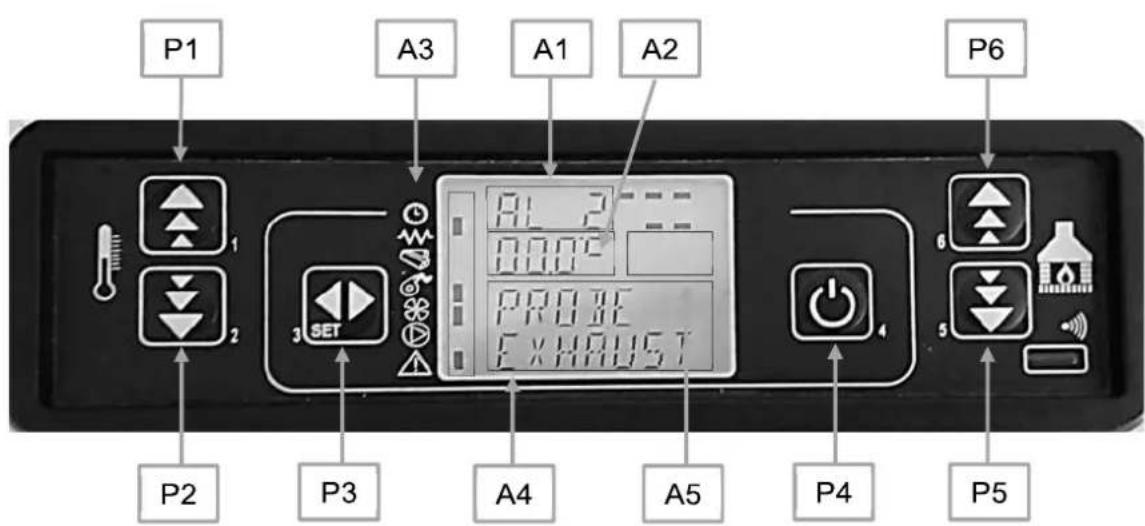
text_image
P1 A3 A1 A2 P6 1 2 3 SET 8L 2 00.00° PROBE EXHAUST 4 6 5 P2 P3 A4 A5 P4 P5F-3
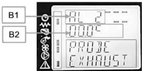
text_image
B1 B2 8L 2 0.00°C PROJEC EXHAUSTF-4

text_image
P2 L1 L4 L2 D1 L5 L3 P3 L0 P1 -1 + - 20.8°C 3F-5

text_image
14:24 26.0 p-3 spento P0 P1 P2 P3 P4 P5 4 5 6 7 P7 P8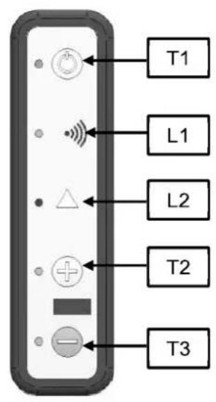
text_image
T1 L1 L2 T2 T3F-6
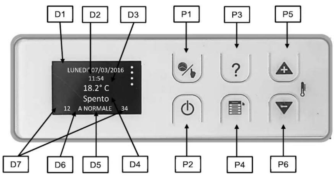
flowchart
graph TD
    A["D1"] --> B["LUNEDI' 07/03/2016 11:54 18.2°C Spento 12 A NORMALE 34"]
    C["D2"] --> B
    D["D3"] --> B
    E["D4"] --> B
    F["D5"] --> B
    G["D6"] --> B
    H["D7"] --> B
    I["P1"] --> J["Image with question mark"]
    K["P3"] --> L["Image with plus sign"]
    M["P5"] --> N["Image with minus sign"]
    O["P2"] --> P["Image with power button"]
    Q["P4"] --> R["Image with document icon"]
    S["P6"] --> T["Image with triangle symbol"]
F-7

flowchart
graph TD
    A["A7-a"] --> B["A7-b"]
    B --> C["A7-c"]
    C --> D["A7-d"]
    D --> E["1 LUNEDI"]
    E --> F["A1"]
    E --> G["A7"]
    E --> H["A4"]
    E --> I["A5"]
    E --> J["A6"]


IMPORTANT: À LIRE ABSOLUMENT

natural_image
Interior view of a dark metal enclosure with a magnifying glass and lid (no visible text or symbols)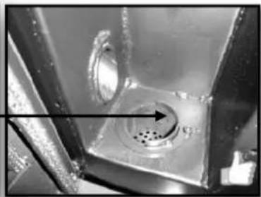
natural_image
Close-up of a metallic square drain with a circular vent and a pipe inserted, showing no text or symbols.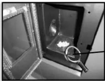
natural_image
Interior view of a mechanical device with a metallic handle and internal components (no visible text or symbols)
natural_image
Close-up of a mechanical component with a central circular feature and an arrow pointing to it (no visible text or symbols)
natural_image
Black top hat filled with small granular material (no text or symbols visible)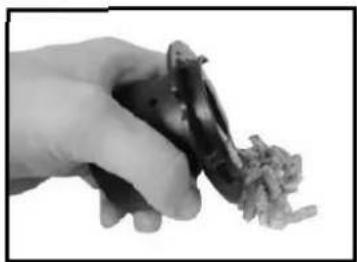
natural_image
Hand holding a dark object with a pile of food, possibly meat or vegetable (no text or symbols visible)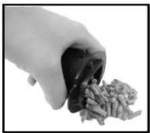
natural_image
Hand holding a small container with granular material, possibly food or chemical (no text or symbols visible)
natural_image
Black-and-white photo showing a dark container with white dots next to a pile of dried plant material (no text or symbols visible)
natural_image
Black-and-white photo of a wooden toolbox containing small cylindrical objects (no visible text or symbols)
natural_image
Hand holding a metal bucket filled with small white granules (no text or symbols visible)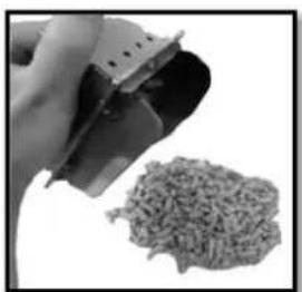
natural_image
Close-up of a hand holding a metal tool next to a pile of granular material (no text or symbols visible)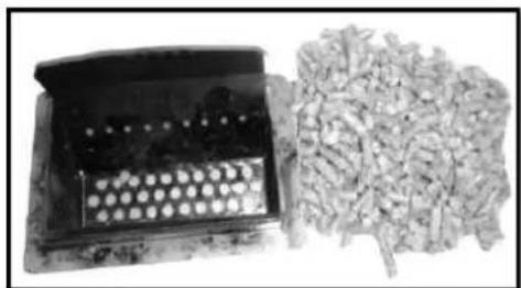
natural_image
Black-and-white photo of a vintage typewriter with a grid of pins, next to a pile of dried plant material (no text or symbols visible)
natural_image
Close-up of a mechanical component with a plastic clip inserted into a housing (no visible text or symbols)
natural_image
Close-up of a mechanical component with a hand inserting a spring into a chamber (no visible text or symbols)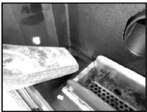
natural_image
Close-up of a mechanical component with a rectangular block and perforated base, next to a circular opening (no visible text or symbols)-
SÉCURITÉ DU PRODUIT ...... p. 84
-
CONDUIT DE FUMÉE...... p. 85
02.01 SORTIE DE TOIT p. 87
02.02 LE TIRAGE p. 87
02.03 PERFORMANCES DU POÊLE p. 87
-
INSTRUCTIONS D'INSTALLATION p. 88
-
INSTALLATION...... p. 90
04.01 POÊLE À PELLET p. 90
04.02 POELE À PELLET AVEC FOUR.... p. 91
04.03 INSERTS À PELLET.... p. 91
04.04 CUISINIÈRE À PELLET ..... p. 92
04.05 CUISINE À PELLET AVEC FOUR p. 92
04.06 CHAUDIÈRE À AIR.... p. 93
04.07 POÈLES HERMÉTIQUES ...... p. 93
- UTILISATION DE L'APPAREIL.... p. 94
05.01 ÉLECTRONIQUE AVEC ÉCRAN LED 6 TOUCHES p. 94 p. 80 F-1
natural_image
Technical drawing of a mechanical assembly with cross-hatched sections (no text or symbols)text_image
MAX A+1/2A Atext_image
Labelled image of a metallic industrial sensor or meter device with visible branding and specifications.02.3 PERFORMANCES DU POÊLE
text_image
Technical diagram showing three mechanical assembly configurations with labeled components and directional arrows indicating motion or force.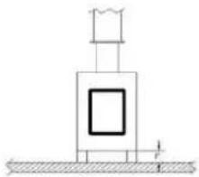
natural_image
Simple line drawing of a mechanical or structural component with no text, numbers, or symbols.text_image
Technical diagram showing a mechanical or electrical component with labeled parts A, B, and C, including dimension lines and a central positive charge symbol.INFLAMMABLE
CHAUDIÉRE À AIR 13,5 KW (15) SPC-15
| MUR ARRIÈRE P = 120 | mm |
| MUR LATÉRAL L = 300 | mm |
| PLANCHER F = - | mm |
| AVANT R = 100 | mm |
CHAUDIÈRE À AIR 18 KW (19,5) SPC-19,5
| MUR ARRIÈRE P = 120 | mm |
| MUR LATÉRAL L = 300 | mm |
| PLANCHER F = - | mm |
| AVANT R = 100 | mm |
CHAUDIÉRE À AIR 18,5 KW (20,5) GP-20
| MUR ARRIÈRE P = 80 | mm |
| MUR LATÉRAL L = 200 | mm |
| PLANCHER F = - | mm |
| AVANT R = 100 | mm |
CUISINIÈRE À PELLET 6,7 KW (7,5) CPV-7627
(libre installation)
| MUR ARRIÈRE P = 10 | mm |
| MUR LATÉRAL L = 200 | mm |
| PLANCHER F = - | mm |
| AVANT R = 1000 | mm |
CUISINIÈRE À PELLET 6,7 KW (7,5) CPV-7627
| MUR ARRIÈRE P = 10 | mm |
| MUR LATÉRAL L = | 10 mm |
| PLANCHER F = - | mm |
| AVANT R = 1000 | mm |
CUISINE À PELLET AVEC FOUR 8,6 KW (9,3) CPF-85
| MUR ARRIÈRE P = 50 | mm |
| MUR LATÉRAL L = | 50 mm |
| PLANCHER F = - | mm |
| AVANT R = 1000 | mm |
PAS INFLAMMABLE
CHAUDIÉRE À AIR 13,5 KW (15) SPC-15
| MUR ARRIÈRE P = 120 | mm |
| MUR LATÉRAL L = 200 | mm |
| PLANCHER F = - | mm |
| AVANT R = 100 | mm |
CHAUDIÈRE À AIR 18 KW (19,5) SPC-19,5
| MUR ARRIÈRE P = 120 | mm |
| MUR LATÉRAL L = 200 | mm |
| PLANCHER F = - | mm |
| AVANT R = 100 | mm |
CHAUDIÉRE À AIR 18,5 KW (20,5) GP-20
| MUR ARRIÈRE P = 80 | mm |
| MUR LATÉRAL L = 100 | mm |
| PLANCHER F = - | mm |
| AVANT R = 100 | mm |
CUISINIÈRE À PELLET 6,7 KW (7,5) CPV-7627
(libre installation)
| MUR ARRIÈRE P = 10 | mm |
| MUR LATÉRAL L = 100 | mm |
| PLANCHER F = - | mm |
| AVANT R = 1000 | mm |
CUISINIÈRE À PELLET 6,7 KW (7,5) CPV-7627
| MUR ARRIÈRE P = 10 | mm |
| MUR LATÉRAL L = | 10 mm |
| PLANCHER F = - | mm |
| AVANT R = 1000 | mm |
CUISINE À PELLET AVEC FOUR 8,6 KW (9,3) CPF-85
| MUR ARRIÈRE P = 50 | mm |
| MUR LATÉRAL L = | 50 mm |
| PLANCHER F = - | mm |
| AVANT R = 1000 | mm |
INFLAMMABLE
POÊLES HERMÉTIQUES SLIM 7 KW (8)
SPE7
| MUR ARRIÈRE P = 50 | mm |
| MUR LATÉRAL L = 300 | mm |
| PLANCHER F = - | mm |
| AVANT R = 1000 | mm |
POÈLE À PELLET 5 KW (6) SP6
| MUR ARRIÈRE P = 250 | mm |
| MUR LATÉRAL L = 300 | mm |
| PLANCHER F = - | mm |
| AVANT R = 1000 | mm |
POÊLE À PELLET 8 KW (9) SPCT8
| MUR ARRIÈRE P = 100 | mm |
| MUR LATÉRAL L = 250 | mm |
| PLANCHER F = - | mm |
| AVANT R = 1000 | mm |
POÊLE À PELLET 7,5 KW (8,6) SPSV
| MUR ARRIÈRE P = 200 | mm |
| MUR LATÉRAL L = 200 | mm |
| PLANCHER F = - | mm |
| AVANT R = 1000 | mm |
POÊLE À PELLET 6,5 KW (7,5) SPIN7,5AT
| MUR ARRIÈRE P = 300- | mm |
| MUR LATÉRAL L = | 150- mm |
| PLANCHER F = | 60- mm |
| AVANT R = 1000 | mm |
POÊLE À PELLET 10,5 KW (12) ANGLE
| MUR ARRIÈRE P = | - mm |
| MUR LATÉRAL L = | - mm |
| PLANCHER F = - | mm |
| AVANT R = 1000 | mm |
PAS INFLAMMABLE
POÊLES HERMÉTIQUES SLIM 7 KW (8)
SPE7
| MUR ARRIÈRE P = 50 | mm |
| MUR LATÉRAL L = 200 | mm |
| PLANCHER F = - | mm |
| AVANT R = 1000 | mm |
POÈLE À PELLET 5 KW (6) SP6
| MUR ARRIÈRE P = 250 | mm |
| MUR LATÉRAL L = 200 | mm |
| PLANCHER F = - | mm |
| AVANT R = 1000 | mm |
POÊLE À PELLET 8 KW (9) SPCT8
| MUR ARRIÈRE P = 100 | mm |
| MUR LATÉRAL L = 150 | mm |
| PLANCHER F = - | mm |
| AVANT R = 1000 | mm |
POÊLE À PELLET 7,5 KW (8,6) SPSV
| MUR ARRIÈRE P = 150 | mm |
| MUR LATÉRAL L = 150 | mm |
| PLANCHER F = - | mm |
| AVANT R = 1000 | mm |
POÊLE À PELLET 6,5 KW (7,5) SPIN7,5AT
| MUR ARRIÈRE P = 200- | mm |
| MUR LATÉRAL L = | 100- mm |
| PLANCHER F = | 60- mm |
| AVANT R = 1000 | mm |
POÊLE À PELLET 10,5 KW (12) ANGLE
| MUR ARRIÈRE P = | - mm |
| MUR LATÉRAL L = | - mm |
| PLANCHER F = - | mm |
| AVANT R = 1000 | mm |
POÊLES HERMÉTIQUES SLIM 8,5 KW (9,5) SPF8.5
| MUR ARRIÈRE P = 50 | mm |
| MUR LATÉRAL L = 150 | mm |
| PLANCHER F = - | mm |
| AVANT R = 1000 | mm |
POÊLES HERMÉTIQUES SLIM 8,5 KW (9,5) SPF8.5
| MUR ARRIÈRE P = 50 | mm |
| MUR LATÉRAL L = 50 | mm |
| PLANCHER F = - | mm |
| AVANT R = 1000 | mm |
POÊLE À PELLET CAN 14 KW (15) SPV-M13
| MUR ARRIÈRE P = 200 | mm |
| MUR LATÉRAL L = 300 | mm |
| PLANCHER F = - | mm |
| AVANT R = 1000 | mm |
POÊLE À PELLET CAN 14 KW (15) SPV-M13
| MUR ARRIÈRE P = 200 | mm |
| MUR LATÉRAL L = 200 | mm |
| PLANCHER F = - | mm |
| AVANT R = 1000 | mm |
POÉLE À PELLET AVEC FOUR 7,5 KW (8,5) SPF8.5
| MUR ARRIÈRE P = 200 | mm |
| MUR LATÉRAL L = 300 | mm |
| PLANCHER F = - | mm |
| AVANT R = 1000 | mm |
POÊLE À PELLET AVEC FOUR 7,5 KW (8,5) SPF8.5
| MUR ARRIÈRE P = 200 | mm |
| MUR LATÉRAL L = 200 | mm |
| PLANCHER F = - | mm |
| AVANT R = 1000 | mm |
POÊLE À PELLET SLIM 4 KW (5,5) SP4
| MUR ARRIÈRE P = 40 | mm |
| MUR LATÉRAL L = 300 | mm |
| PLANCHER F = - | mm |
| AVANT R = 1000 | mm |
POÊLE À PELLET SLIM 4 KW (5,5) SP4
| MUR ARRIÈRE P = 40 | mm |
| MUR LATÉRAL L = 200 | mm |
| PLANCHER F = - | mm |
| AVANT R = 1000 | mm |
POÊLE À PELLET CAN 7,5 KW (9) SPCA7,5
| MUR ARRIÈRE P = 250 | mm | MUR ARRIÈRE P = 200 | mm | MU |
| MUR LATÉRAL L = 250 | mm | MUR LATÉRAL L = 200 | mm | MU |
| PLANCHER F = - | mm | PLANCHER F = - | mm | PL |
| AVANT R = 1000 | mm | AVANT R = 1000 | mm | AV |
POÊLE À PELLET CAN 7,5 KW (9) SPCA7,5
POÊLE À PELLET 11,5 KW (13,5) SPV-M11S
| MUR ARRIÈRE P = 200 | mm |
| MUR LATÉRAL L = 300 | mm |
| PLANCHER F = - | mm |
| AVANT R = 1000 | mm |
POÊLE À PELLET SLIM CAN 9,3 KW (10,5) SPCS9
| MUR ARRIÈRE P = 50 | mm |
| MUR LATÉRAL L = 200 | mm |
| PLANCHER F = - | mm |
| AVANT R = 1000 | mm |
POÊLE À PELLET SLIM 6,5 KW (7,5)
| MUR ARRIÈRE P = 10 | mm |
| MUR LATÉRAL L = 300 | mm |
| PLANCHER F = - | mm |
| AVANT R = 1000 | mm |
POÊLE À PELLET SLIM 9 KW (11) SPVM-9
| MUR ARRIÈRE P = 100 | mm |
| MUR LATÉRAL L = 250 | mm |
| PLANCHER F = - | mm |
| AVANT R = 1000 | mm |
POÈLE À PELLET 8 KW (9,3) SPSC8C - SPSC8
| ARRIÈRE P = 200 | mm |
| LATÉRAL L = 200 | mm |
| VCHER F = - | mm |
| VT R = 1000 | mm |
POÊLE À PELLET 11,5 KW (13,5) SPV-M11S
| MUR ARRIÈRE P = 200 | mm |
| MUR LATÉRAL L = 200 | mm |
| PLANCHER F = - | mm |
| AVANT R = 1000 | mm |
POÊLE À PELLET SLIM CAN 9,3 KW (10,5) SPCS9
| MUR ARRIÈRE P = 50 | mm |
| MUR LATÉRAL L = 150 | mm |
| PLANCHER F = - | mm |
| AVANT R = 1000 | mm |
POÊLE À PELLET SLIM 6,5 KW (7,5)
| MUR ARRIÈRE P = 10 | mm |
| MUR LATÉRAL L = 200 | mm |
| PLANCHER F = - | mm |
| AVANT R = 1000 | mm |
POÊLE À PELLET SLIM 9 KW (11) SPVM-9
| MUR ARRIÈRE P = 100 | mm |
| MUR LATÉRAL L = 150 | mm |
| PLANCHER F = - | mm |
| AVANT R = 1000 | mm |
POÊLE À PELLET 8 KW (9,3) SPSC8C - SPSC8
| MUR ARRIÈRE P = 100 | mm |
| MUR LATÉRAL L = 100 | mm |
| PLANCHER F = - | mm |
| AVANT R = 1000 | mm |
POÈLE À PELLET SLIM 4 KW (5,5) SP4
| MUR ARRIÈRE P = 40 | mm | MUR ARRIÈRE P = 40 | mm |
| MUR LATÉRAL L = 300 | mm | MUR LATÉRAL L = 200 | mm |
| PLANCHER F = - | mm | PLANCHER F = - | mm |
| AVANT R = 1000 | mm | AVANT R = 1000 | mm |
POÈLE À PELLET SLIM 4 KW (5,5) SP4
| INSERTS À PELLET | INSERTS 9,5 KW(11) IP9,5 | INSERTS 6,5 KW(7,5) IPGN |
| POSTÉRIEUR | 100 | 180 |
| LATÉRALE | 100 | 180 |
| FRONTAL | 1500 | 1000 |
| PLANCHER | 50 | 10 |
| A cm2 | 500 | 450 |
| B cm2 | 500 | 450 |
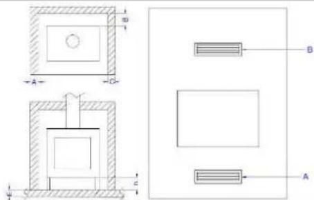
text_image
Technical diagram showing cross-sectional views and labeled components A, B, C with dimension annotationsPOÊLE COIN INSTALLATION
natural_image
Technical line drawing of a mechanical device with dimension annotations (no readable text or symbols)VITRE
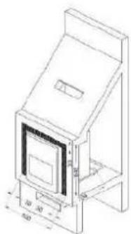
natural_image
Technical line drawing of a mechanical or architectural component with dimension annotations (no readable text or symbols)INSERT 11 KW - AMOVIBLE POUR LE CHARGEMENT
natural_image
Technical line drawing of a mechanical device with mounting bracket and internal components (no text or symbols)DÉVISSER LES VIS A, B, C ET D EN SUIVANT LES INSTRUCTIONS DU DEMONTAGE DE L'INSERT DES RAILS. NOUS CONSEILLONS D'UTILISER UN CHEVALET POUR POSER L'INSERT UNE FOIS EXTRAI, FIXER LA PLAQUE ET REMONTER L'INSERT SUR LES RAILS PUIS LE REMETTRE EN PLACE.
IMPORTANT: LA LONGUEUR DES TUYAUX D'ECHAPPEMENT DOIT AVOIR UNE LONGUEUR MAXIMALE DE 6 MÉTRES, DIAMÉTRE 80 mm, CHAQUE COURBE À 90° OU RACCORD À (T) EST CONSIDERÉ COMMENT 1 MÉTRE DE TUYAUX.
AVANT D' EFFECTUER LA CONNEXION DE LA CHEMINÉE, POUR GARANTIR LA BONNE PERFORMANCE DU POELE, IL FAUT DE RESPECTER LES TYPES DE L'INSTALLATION SUIVANTS:
natural_image
Close-up of mechanical components with no visible text or symbolsINTERRUPTEUR ON/OFF
BORNES SONDES D'AMBIANCE OU
RÉCÉPTEUR RADIOCOMMANDE
INTERRUPTEUR DE SECOURS
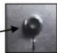
COUVERCLE PELLE
JOINT COUVERCLE PELLE
THERMOSTAT DE SÉCURITÉ
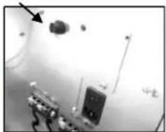
natural_image
Close-up of a small electronic device with a mounted sensor and a small dark component, no visible text or symbols.
natural_image
Exterior view of a medical or laboratory instrument with a screen and black arrows pointing to features (no visible text or symbols)natural_image
Close-up of a mechanical component with cylindrical and rectangular parts, no visible text or symbolsnatural_image
Close-up of a mechanical component with multiple slots and a switch (no visible text or symbols)INTERRUPTEUR
DE SECOURS
THERMOSTAT DE
SÉCURITÉ
INTERRUPTEUR ON/OFF
SONDE DE TEMPÉRATURE
AMBIANTE
RÉCÉPTEUR RADIOCOMMANDE
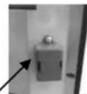
05.1 ÉLECTRONIQUE AVEC ÉCRAN LED 6 TOUCHES
LED CHRONO ACTIVÉ (L1):
UT01 --- RÉGLAGE JOUR ACTUEL (DAY7 = DIMANCHE)
PROGRAMME 1
UT05 --- I" MARCHE (ex. : 07 h 00)
UT06 --- I" ARRÊT (ex. : 07 h 00)
UT07 --- CONFIRMER JOURS (ex.: DAY1-OFF /DAY2-OFF/DAY3-OFF/DAY4-OFF/DAY5-OFF/DAY6-ON/DAY7-ON)
PROGRAMME 2
UT08 --- II" MARCHE (ex. : 18 h 00)
UT09 --- II" ARRÊT (ex. : 24 h 00)
UT10 --- CONFIRMER JOURS (ex. : DAY1 -ON /DAY2-ON/DAY3-ON/DAY4-ON/DAY5-ON/DAY6-OFF/DAY7-OFF)
Menu M4 – SET CHRONO
Sous-menu M4 - 1 PERMETT CHRONO
TSET < (Tambiante - Pr43)
Menu M7 - MODE RONFLEUR
Quand «OFF» désactive la signalisation sonore.
Menu M8 - CHARGE INITIALE
LED (L2) chronothermostat
LED (L3) ON/OFF
LED (L4) alarme
Menu M02 – SET CHRONO
Sous-menu M2 - 1 HABILITE CHRONO
Bouton (P4) On / Off.
Menù M1 – SET HORLOGE
Menu M2 – SET CHRONO
Sous-menu M2 - 1 SCRIVATION CHRONO
Menu M3 – SET CHRONO
Sous-menu M3 - 01 PERMETT-CHRONO
TSET < (Tambiente - Pr43)
Menu M7 - MODE RONFLEUR
05.6 RADIOCOMMANDE AVEC ÉCRAN LCD
natural_image
Close-up of a black remote control device with four buttons (no visible text or symbols)06. NETTOYAGE ET ENTRETIEN
AVANT-PROPOS
natural_image
Close-up of a hand using a tool to clean or repair a car panel, no visible text or symbolsnatural_image
Interior view of a dark room with a metal door and a magnifying glass (no visible text or symbols)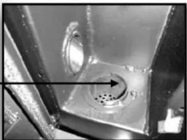
natural_image
Close-up of a metallic square drain with a circular vent and perforated center, showing an arrow pointing to the drain (no text or symbols visible)
natural_image
Close-up of a mechanical component with a magnifying glass and internal components (no visible text or symbols)
natural_image
Close-up of a mechanical component with a central circular feature and an arrow pointing to a feature (no visible text or symbols)
natural_image
Black top hat filled with granular material, no visible text or symbols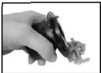
natural_image
Close-up of a hand holding a dark, irregular object with a textured surface (no visible text or symbols)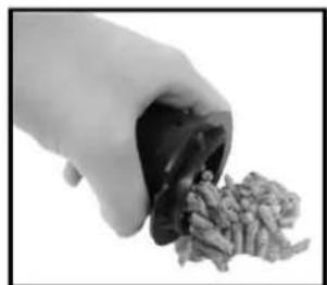
natural_image
Hand holding a small container with granular material, possibly dried plant matter or salt (no text or symbols visible)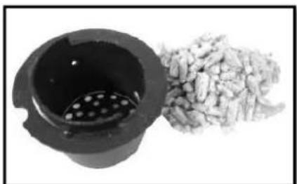
natural_image
Close-up of a dark mechanical component with white circular holes next to a pile of granular material (no text or symbols visible)
natural_image
Black-and-white photo of a wooden toolbox filled with small objects, no visible text or symbols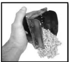
natural_image
Hand using a tool to spread grain or seeds from a metal container (no text or symbols visible)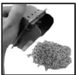
natural_image
Close-up of a hand holding a tool next to a pile of granular material (no text or symbols visible)
natural_image
Black-and-white photo of a wooden box with circular indentations next to a pile of dried plant material (no text or symbols visible)
natural_image
Close-up of a mechanical component with a plastic bag attached to a housing (no visible text or symbols)
natural_image
Close-up of a mechanical component with a cylindrical rod inserted into a housing (no visible text or symbols)
natural_image
Close-up of a mechanical component with a rectangular block and perforated base, no visible text or symbolsF-1
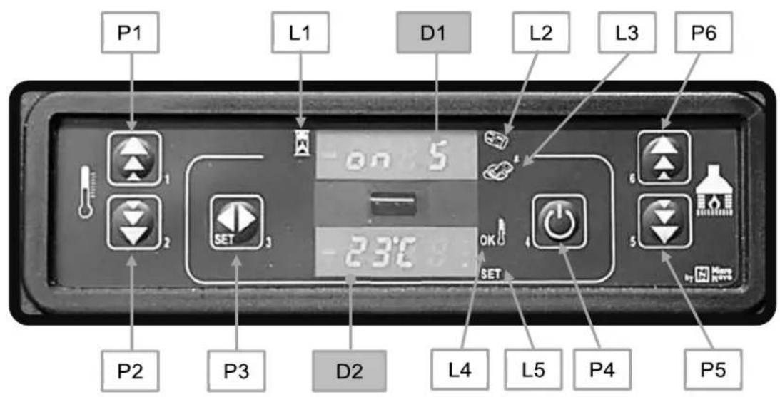
text_image
P1 L1 D1 L2 L3 P6 1 SET 3 -23°C OK SET L4 L5 P4 P5 P2 P3 D2F-2

text_image
P1 A3 A1 A2 P6 P2 P3 3 SET 81 2 0.00°C PROBE EXHAUST A4 A5 P4 P5F-3
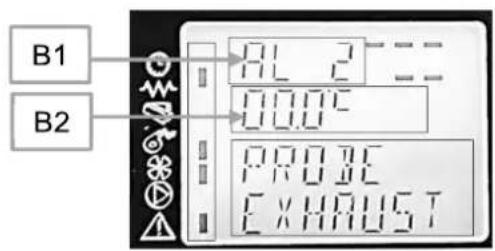
text_image
B1 B2 80.0°C PROFE EXHAUSTF-4
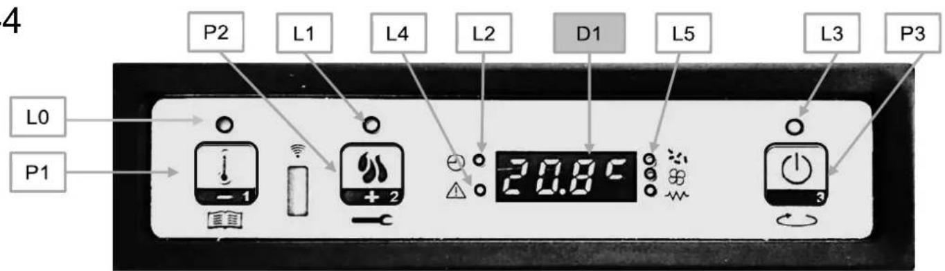
text_image
P2 L1 L4 L2 D1 L5 L3 P3 L0 P1 -1 +2 20.8°C 3F-5

text_image
14:24 26.0 p-3 spento P0 P1 P2 P3 P4 P5 4 5 6 7 P7 P8
text_image
T1 L1 L2 T2 T3F-6
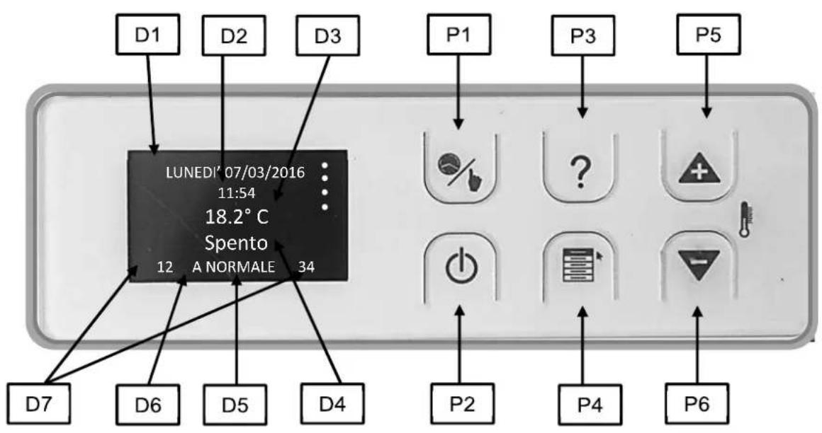
flowchart
graph TD
    A["LUNEDI' 07/03/2016 11:54 18.2°C Spento 12 A NORMALE 34"] --> B["D1"]
    A --> C["D2"]
    A --> D["D3"]
    A --> E["D4"]
    A --> F["D6"]
    A --> G["D7"]
    H["P1"] --> I["Button icon with question mark"]
    J["P3"] --> K["Button icon with plus sign"]
    L["P5"] --> M["Button icon with minus sign"]
    N["P2"] --> O["Button icon with power button"]
    P["P4"] --> Q["Button icon with document icon"]
    R["P6"] --> S["Button icon with minus sign"]
F-7

flowchart
graph TD
    A["A7-a"] --> B["A7-b"]
    B --> C["A7-c"]
    C --> D["A7-d"]
    D --> E["1 LUNEDI"]
    E --> F["A2"]
    E --> G["A3"]
    F --> H["0 1 2 3 4 5 6 7 8 9 10 11"]
    G --> I["12 13 14 15 16 17 18 19 20 21 22 23"]
    I --> J["..."]
    J --> K["A4"]
    J --> L["A5"]
    J --> M["A6"]

Durchmesser: 6 ±0.5 mm
text_image
Close-up of a metallic cylindrical device with a label and printed text, likely indicating a technical or informational specification.Zugregler
02.2 EFFIZIENZ DES OFENS
natural_image
Technical diagram of a vertical mechanical assembly with red arrows indicating force or movement, shown in two orthogonal views (no text or labels)
natural_image
Simple line drawing of a mechanical or structural component with no text, numbers, or symbolsBRENNSTOFFEN
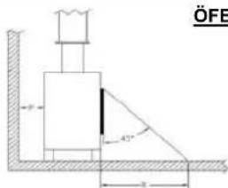
text_image
ÖFE 4" 2"text_image
Technical diagram showing a mechanical or structural component with labeled parts and directional arrowsPELLETÖFEN 8 KW (9) SPCT8
| RÜCKWAND P = 100 | mm |
| SEITENWAND L = 250 | mm |
| BODEN F = - | mm |
| VORDERSEITE R = 1000 | mm |
PELLETÖFEN 8 KW (9) SPCT8
| RÜCKWAND P = 100 | mm |
| SEITENWAND L = 150 | mm |
| BODEN F = - | mm |
| VORDERSEITE R = 1000 | mm |
PELLETÖFEN 7,5 KW (8,6) SPSV
| RÜCKWAND P = | 200 mm |
| SEITENWAND L = | 200 mm |
| BODEN F = - | mm |
| VORDERSEITE R = 1000 | mm |
PELLETÖFEN 7,5 KW (8,6) SPSV
| RÜCKWAND P = | 150 mm |
| SEITENWAND L = | 150 mm |
| BODEN F = - | mm |
| VORDERSEITE R = 1000 | mm |
PELLETÖFEN 6,5 KW (7,5) SPIN7,5AT
| RÜCKWAND P = | 300- mm |
| SEITENWAND L = | 150- mm |
| BODEN F = | 60- mm |
| VORDERSEITE R = 1000 | mm |
PELLETÖFEN 6,5 KW (7,5) SPIN7,5AT
| RÜCKWAND P = | 200- mm |
| SEITENWAND L = | 100- mm |
| BODEN F = | 60- mm |
| VORDERSEITE R = 1000 | mm |
PELLETÖFEN 10,5 KW (12) CORNER
| RÜCKWAND P = - | mm |
| SEITENWAND L = - | mm |
| BODEN F = - | mm |
| VORDERSEITE R = 1000 | mm |
PELLETÖFEN 10,5 KW (12) CORNER
| RÜCKWAND P = - | mm |
| SEITENWAND L = - | mm |
| BODEN F = - | mm |
| VORDERSEITE R = 1000 | mm |
PELLETÖFEN 11,5 KW (13,5) SPV-M11S
| RÜCKWAND P = 200 | mm |
| SEITENWAND L = 300 | mm |
| BODEN F = - | mm |
| VORDERSEITE R = 1000 | mm |
PELLETÖFEN 11,5 KW (13,5) SPV-M11S
| RÜCKWAND P = 200 | mm |
| SEITENWAND L = 200 | mm |
| BODEN F = - | mm |
| VORDERSEITE R = 1000 | mm |
PELLETÖFEN SLIM KAN 9,3 KW (10,5) SPCS9
| RÜCKWAND P = | 50 mm |
| SEITENWAND L = | 200 mm |
| BODEN F = - | mm |
| VORDERSEITE R = 1000 | mm |
PELLETÖFEN SLIM CAN 9,3 KW (10,5) SPCS9
| RÜCKWAND P = | 50 mm |
| SEITENWAND L = | 150 mm |
| BODEN F = - | mm |
| VORDERSEITE R = 1000 | mm |
PELLETÖFEN SLIM 6,5 KW (7,5)
| RÜCKWAND P = 10 | mm |
| SEITENWAND L = 300 | mm |
| BODEN F = - | mm |
| VORDERSEITE R = 1000 | mm |
PELLETÖFEN SLIM 6,5 KW (7,5)
| RÜCKWAND P = 10 | mm |
| SEITENWAND L = 200 | mm |
| BODEN F = - | mm |
| VORDERSEITE R = 1000 | mm |
PELLETÖFEN SLIM 9 KW (11) SPVM-9
| RÜCKWAND P = 100 | mm |
| SEITENWAND L = 250 | mm |
| BODEN F = - | mm |
| VORDERSEITE R = 1000 | mm |
PELLETÖFEN SLIM 9 KW (11) SPVM-9
| RÜCKWAND P = 100 | mm |
| SEITENWAND L = 150 | mm |
| BODEN F = - | mm |
| VORDERSEITE R = 1000 | mm |
PELLETÖFEN 8 KW (9,3) SPSC8C - SPSC8
| RÜCKWAND P = | 200 mm |
| SEITENWAND L = | 200 mm |
| BODEN F = | - mm |
| VORDERSEITE R = | 1000 mm |
PELLETÖFEN 8 KW (9,3) SPSC8C - SPSC8
| RÜCKWAND P = | 100 mm |
| SEITENWAND L = | 100 mm |
| BODEN F = | - mm |
| VORDERSEITE R = | 1000 mm |
OFENEINSÄTZE MIT PELLETS
| HERD 9,5 KW(11) IP9,5 | HERD 6,5 KW(7,5) IPGN | |
| HINTEN | 100 | 180 |
| SEITLICH | 100 | 180 |
| FRONTAL | 1500 | 1000 |
| BODEN | 50 | 10 |
| A cm2 | 500 | 450 |
| B cm2 | 500 | 450 |
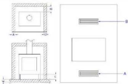
text_image
Technical diagram showing cross-sectional views of a mechanical or electrical component with labeled dimensions and section markers A and B.natural_image
Isometric technical drawing of a mechanical device with dimension annotations (no readable text or symbols)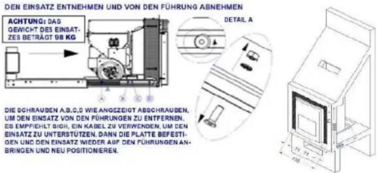
04.4 HERD MIT PALLETS
natural_image
Close-up of electrical components with no visible text or symbolsnatural_image
Interior view of a room with a wall-mounted device and a small circular object, no visible text or symbols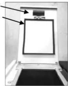
natural_image
Exterior view of a white scientific instrument with a display and control panel (no visible text or symbols)natural_image
Close-up of a black metal mechanical component with cylindrical pins and a vertical rod (no visible text or symbols)natural_image
Close-up of a computer interface panel with buttons and connectors (no visible text or symbols)natural_image
Close-up of a white electronic device with vertical slots and a small black mark (no visible text or symbols)ALAR COOL FIRE - Alarm Stromausfall
Menu M4 – SET CHRONO
Untermenü M4 - 1 FREIGABE CHRONO
M02 Menü – SET CHRONO
Untermenü M2 - 1 – CHRONO FREIGABE
Menü M2 – SET CHRONO
Untermenü M2 - 1 CHRONO FREIGABE
natural_image
Black rectangular electronic device with four buttons and a plus/minus signs (no visible text or symbols)natural_image
Close-up of a hand using a tool to clean or store items on a black vehicle edge (no visible text or symbols)NUR FÜR KÜCHENOFEN
natural_image
Interior view of a dark metal safe with a magnifying glass resting inside (no visible text or symbols)
natural_image
Close-up of a metal square drain with a circular vent and a circular inlet, showing an arrow pointing to the drain (no text or symbols visible)
natural_image
Interior view of a mechanical or industrial device with a metallic door and a magnifying glass (no visible text or symbols)
natural_image
Close-up of a mechanical component with a central bolt and flange, showing no visible text or symbols.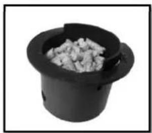
natural_image
Black top hat filled with granular material, no visible text or symbols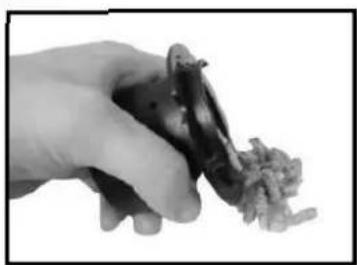
natural_image
Hand holding a dark object with a pile of food, possibly meat or vegetable (no text or symbols visible)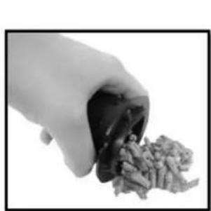
natural_image
Hand holding a small container with granular material, possibly corn kernels or grains (no text or symbols visible)
natural_image
Close-up of a black mechanical component with a perforated lid and a pile of white granular material (no text or symbols visible)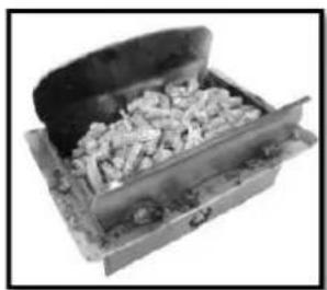
natural_image
Black-and-white photo of a wooden toolbox filled with small debris (no text or symbols visible)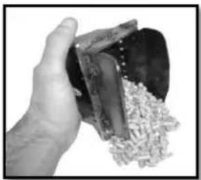
natural_image
Hand holding a metal bucket filled with small white pellets (no text or symbols visible)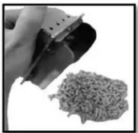
natural_image
Close-up of a hand holding a metal tool next to a pile of granular material (no text or symbols visible)
natural_image
Black-and-white photo of a traditional typewriter and scattered dried plant material (no text or symbols visible)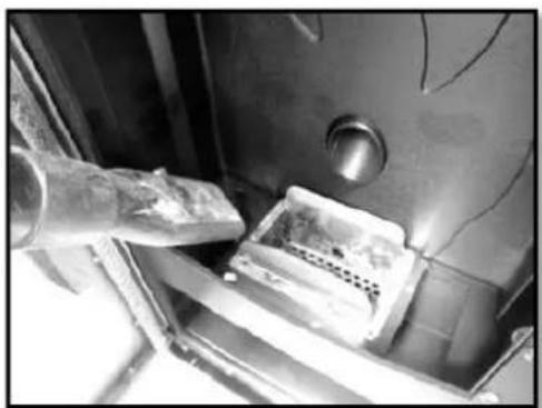
natural_image
Close-up of a mechanical component with a plastic tag attached to a housing (no visible text or symbols)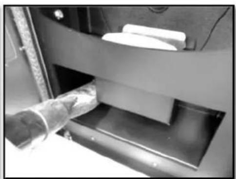
natural_image
Close-up of a hand pressing down on a mechanical component (no visible text or symbols)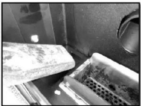
natural_image
Close-up of a metal tray with a rectangular block placed next to a perforated metal grate, next to a circular object (no visible text or symbols)F-1
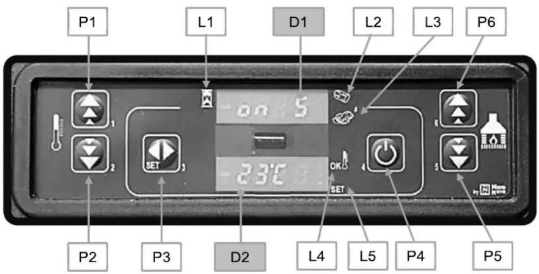
text_image
P1 L1 D1 L2 L3 P6 P2 P3 SET 23°C OK SET L4 L5 P4 P5F-2

text_image
P1 A3 A1 A2 P6 1 2 3 SET 81 2 000°C PROJEC EXHARUST P2 P3 A4 A5 P4 P5F-3
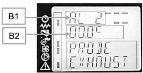
text_image
B1 B2 AL 2 0.00°C PROJSE EXHAUSTF-4

text_image
P2 L1 L4 L2 D1 L5 L3 P3 L0 P1 -1 + - 20.8°C 3F-5

text_image
14:24 26.0 p-3 spento P0 P1 P2 P3 P4 P5 4 5 6 7 P7 P8
text_image
T1 L1 L2 T2 T3F-6

flowchart
graph TD
    A["D1"] --> B["LUNEDI '07/03/2016 11:54 18.2°C Spento 12 A NORMALE 34"]
    C["D2"] --> B
    D["D3"] --> B
    E["D4"] --> B
    F["D5"] --> B
    G["D6"] --> B
    H["D7"] --> B
    I["P1"] --> J["Button icon"]
    K["P3"] --> L["Button icon"]
    M["P5"] --> N["Button icon"]
    O["P2"] --> P["Button icon"]
    Q["P4"] --> R["Button icon"]
    S["P6"] --> T["Button icon"]
F-7
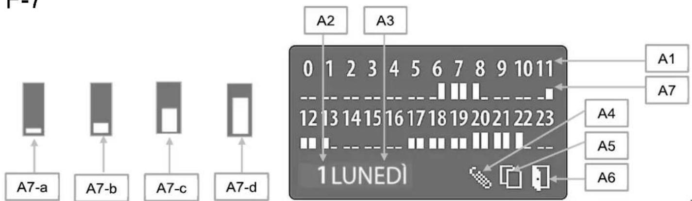
flowchart
graph TD
    A["A7-a"] --> B["A7-b"]
    B --> C["A7-c"]
    C --> D["A7-d"]
    D --> E["1 LUNEDI"]
    E --> F["A1"]
    E --> G["A7"]
    E --> H["A4"]
    E --> I["A5"]
    E --> J["A6"]
-
SEGURIDAD DEL PRODUCTO...... p. 160
-
CONDUCTO DE HUMOS.... p. 161
02.01 REMATE DE LA CHIMENEA.... p. 163
02.02 TIRO p. 163
02.03 EFICACIA DE LA ESTUFA.... p. 164
text_image
NO ESTRANOU- LIMBERTO INCLINADOR, INFERIOR ASSCONDUCTO DE HUMOS EXISTENTE (TRADICIONAL)
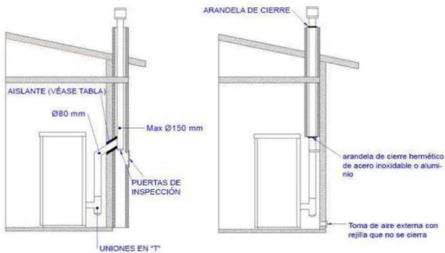
natural_image
Pure diagram of two vertical cylindrical structures with directional arrows, no text or symbols presentNO
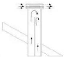
natural_image
Pure mechanical diagram showing a vertical shaft with internal flow arrows and directional arrows, no text or symbols present.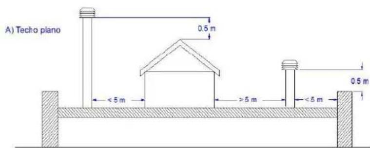
text_image
A) Techo plano 0.5 m < 5 m >5 m < 5 m 0.5 m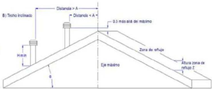
text_image
Label on a circular metallic device showing product name, specifications, and manufacturer informationnatural_image
Three schematic diagrams of vertical structural elements with directional arrows indicating movement or force, no text or symbols present.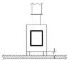
natural_image
Technical line drawing of a mechanical assembly with no visible text or symbolsINFLAMABLE
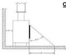
text_image
CNO
CALDERAS Y ESTUFAS

text_image
Technical diagram showing a mechanical or structural component with labeled parts A, B, and h, including dimension L and reference lines.INFLAMABLE
NO INFLAMABLE
CALDERA DE AIRE 13,5 KW (15) SPC-15
| PARED POSTERIOR P = 120 | mm |
| PARED LATERAL L = 300 | mm |
| PAVIMENTO F = - | mm |
| FRENTE R = 100 | mm |
CALDERA DE AIRE 13,5 KW (15) SPC-15
| PARED POSTERIOR P = 120 | mm |
| PARED LATERAL L = 200 | mm |
| PAVIMENTO F = - | mm |
| FRENTE R = 100 | mm |
CALDERA DE AIRE 18 KW (19,5) SPC-19,5
| PARED POSTERIOR P = 120 | mm |
| PARED LATERAL L = 300 | mm |
| PAVIMENTO F = - | mm |
| FRENTE R = 100 | mm |
CALDERA DE AIRE 18 KW (19,5) SPC-19,5
| PARED POSTERIOR P = 120 | mm |
| PARED LATERAL L = 200 | mm |
| PAVIMENTO F = - | mm |
| FRENTE R = 100 | mm |
CALDERA DE AIRE 18,5 KW (20,5) GP-20
| PARED POSTERIOR P = 80 | mm |
| PARED LATERAL L = 200 | mm |
| PAVIMENTO F = - | mm |
| FRENTE R = 100 | mm |
CALDERA DE AIRE 18,5 KW (20,5) GP-20
| PARED POSTERIOR P = 80 | mm |
| PARED LATERAL L = 100 | mm |
| PAVIMENTO F = - | mm |
| FRENTE R = 100 | mm |
ESTUFA HERMÉTICA SLIM 7 KW (8) SPE7
| PARED POSTERIOR P = 50 | mm |
| PARED LATERAL L = 300 | mm |
| PAVIMENTO F = - | mm |
| FRENTE R = 1000 | mm |
ESTUFAS DE PELLET 5 KW (6) SP6
| PARED POSTERIOR P = 250 | mm |
| PARED LATERAL L = 300 | mm |
| PAVIMENTO F = - | mm |
| FRENTE R = 1000 | mm |
ESTUFAS DE PELLET 8 KW (9) SPCT8
| PARED POSTERIOR P = 100 | mm |
| PARED LATERAL L = 250 | mm |
| PAVIMENTO F = - | mm |
| FRENTE R = 1000 | mm |
ESTUFA HERMÉTICA SLIM 7 KW (8) SPE7
| PARED POSTERIOR P = 50 | mm |
| PARED LATERAL L = 200 | mm |
| PAVIMENTO F = - | mm |
| FRENTE R = 1000 | mm |
ESTUFAS DE PELLET 5 KW (6) SP6
| PARED POSTERIOR P = 250 | mm |
| PARED LATERAL L = 200 | mm |
| PAVIMENTO F = - | mm |
| FRENTE R = 1000 | mm |
ESTUFAS DE PELLET 8 KW (9) SPCT8
| PARED POSTERIOR P = 100 | mm |
| PARED LATERAL L = 150 | mm |
| PAVIMENTO F = - | mm |
| FRENTE R = 1000 | mm |
text_image
Technical diagram showing cross-sectional views of a mechanical or electrical component with labeled parts A and Bsòlo para ESTUFA HERMÉTICA
text_image
1 2 3 4 EFA CLEAR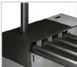
natural_image
Close-up of a mechanical component with cylindrical and rectangular parts, no visible text or symbolsnatural_image
Close-up of electrical components with no visible text or symbolsINTERRUPTOR ON/OFF
BORNES SONDAS AMBIENTE O
TERMOSTATOS
RECEPTOR RADIOCOMANDO
INTERRUPTOR DE EMERGENCIA
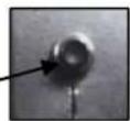
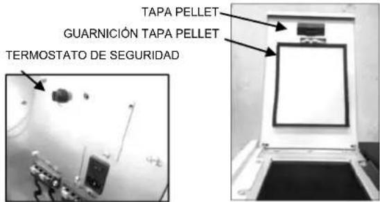
natural_image
Close-up of a metallic panel with vertical slots and a small mark (no visible text or symbols)TSET < (Tambiente - Pr43)
natural_image
Close-up of a metallic electronic device with ventilation grilles and a yellow warning label (no readable text or symbols)05.3 ÉLETRÓNICA CON DISPLAY LED 3 PULSADORES N. 100
natural_image
Close-up of a control panel with vertical slots and a small warning label (no readable text or symbols)NIVEL (A7-b) ECONOMY
NIVEL (A7-c) NORMAL
NIVEL (A7-d) CONFORT
NIVEL (A7-b) ECONOMY
NIVEL (A7-c) NORMAL
NIVEL (A7-d) CONFORT
natural_image
Black rectangular electronic device with four buttons and a red indicator (no visible text or symbols)INTRODUCCIÓN
natural_image
Close-up of a hand holding a black tool near a red vehicle's side panel (no visible text or symbols)flowchart
graph TD
    A["D1"] --> B["LUNEDI '07/03/2016 11:54 18.2°C Spento 12 A NORMALE 34"]
    C["D2"] --> B
    D["D3"] --> B
    E["D4"] --> B
    F["D5"] --> B
    G["D6"] --> B
    H["P1"] --> I["Control buttons with icons"]
    J["P3"] --> K["Control buttons with question mark"]
    L["P5"] --> M["Control buttons with plus sign"]
    N["P2"] --> O["Control buttons with power icon"]
    P["P4"] --> Q["Control buttons with document icon"]
    R["P6"] --> S["Control buttons with minus sign"]
F-7
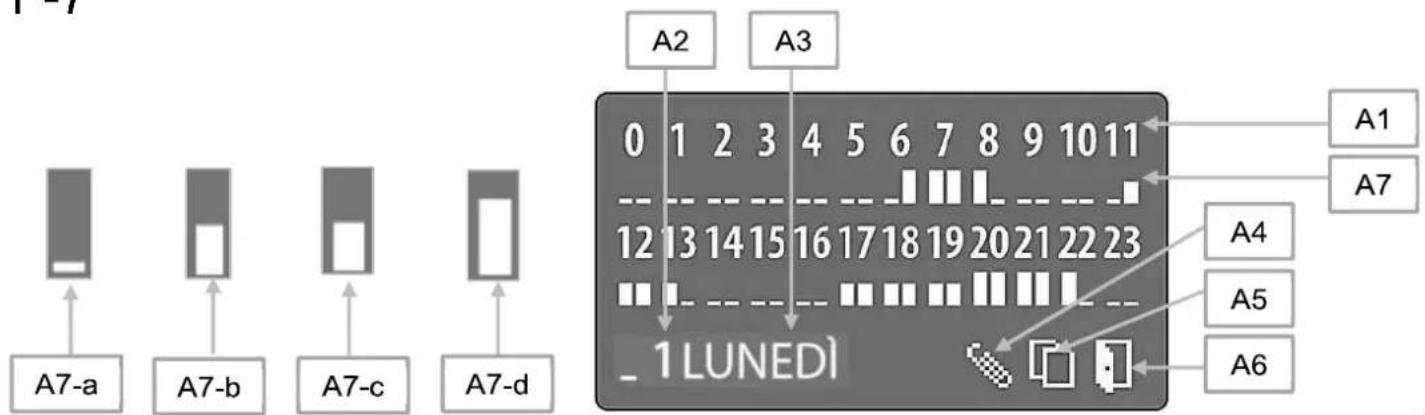
flowchart
graph TD
    A["A7-a"] --> B["A7-b"]
    B --> C["A7-c"]
    C --> D["A7-d"]
    D --> E["0 1 2 3 4 5 6 7 8 9 10 11"]
    E --> F["12 13 14 15 16 17 18 19 20 21 22 23"]
    F --> G["- 1 LUNEDI"]
    G --> H["A4"]
    G --> I["A5"]
    G --> J["A6"]
    H --> K["A1"]
    H --> L["A7"]

IMPORTANTE: A LER ABSOLUTAMENTE

natural_image
Interior view of a mechanical device with a magnifying glass and circular component (no visible text or symbols)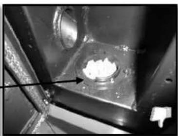
natural_image
Close-up of a metal bracket with a circular hole and an arrow pointing to a small white object (no text or symbols visible)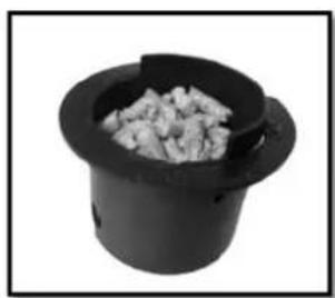
natural_image
Black top hat filled with small white granular material, no visible text or symbols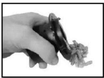
natural_image
Hand holding a small object with granular texture, possibly food or material (no visible text or symbols)
natural_image
Hand pouring granular material from a dark container (no text or symbols visible)
natural_image
Close-up of a dark, circular container with white spots next to a pile of small, textured objects (no text or symbols visible)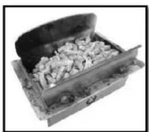
natural_image
Black-and-white photo of a wooden toolbox filled with small cylindrical objects (no text or symbols visible)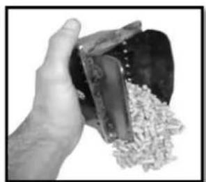
natural_image
Hand holding a metal tool with scattered seeds, no visible text or symbols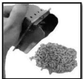
natural_image
Close-up of a hand holding a metal tool next to a pile of granular material (no text or symbols visible)
natural_image
Black-and-white photo showing a small open box with circular indentations next to a pile of dried plant material (no text or symbols visible)
natural_image
Close-up of a mechanical component with a cylindrical tool inserted into a housing (no visible text or symbols)
natural_image
Close-up of a hand pressing down on a mechanical component (no visible text or symbols)
natural_image
Close-up of a mechanical component with a textured rectangular block and a perforated base (no visible text or symbols)-
SEGURANÇA DO PRODUTO ...... p. 198
-
CHAMINÉ.... p. 199
02.01 CONE DA CHAMINÉ.... p. 201
02.02 TIRAGEM p. 201
02.03 EFICIÊNCIA DA ESTUFA.... p. 202
SALAMANDRAS A PELLETS 8 KW (9) SPCT8
text_image
MAX A+1/2A A02.1 CONE DA CHAMINÉ
text_image
Close-up of a metallic cylindrical device with a label showing technical specifications and a small inset image.02.3 EFICIÊNCIA DA ESTUFA
text_image
CHAMINE CHAMINE CHAMINEnatural_image
Three schematic diagrams of vertical structural supports with red arrows indicating force directions, no text or symbols present.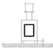
natural_image
Simple line drawing of a mechanical or electrical component with no text, numbers, or symbolsINFLAMÁVEL
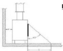
text_image
Technical diagram showing a mechanical setup with labeled dimensions and componentsNÃO INFLAMÁVEL
ESTUFAS E CALDEIRAS
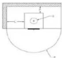
text_image
Technical diagram showing a mechanical or structural component with labeled parts A, B, and L, including a circular feature and curved base.INFLAMÁVEL
NÃO INFLAMÁVEL
CALDEIRA A AR 13,5 KW (15) SPC-15
| PAREDE POSTERIOR P = 120 | mm |
| PAREDE LATERAL L = 300 | mm |
| PAVIMENTO F = - | mm |
| FRENTE R = 100 | mm |
CALDEIRA A AR 18 KW (19,5) SPC-19,5
| PAREDE POSTERIOR P = 120 | mm |
| PAREDE LATERAL L = 300 | mm |
| PAVIMENTO F = - | mm |
| FRENTE R = 100 | mm |
CALDEIRA A AR 13,5 KW (15) SPC-15
| PAREDE POSTERIOR P = 120 | mm |
| PAREDE LATERAL L = 200 | mm |
| PAVIMENTO F = - | mm |
| FRENTE R = 100 | mm |
CALDEIRA A AR 18 KW (19,5) SPC-19,5
| PAREDE POSTERIOR P = 120 | mm |
| PAREDE LATERAL L = 200 | mm |
| PAVIMENTO F = - | mm |
| FRENTE R = 100 | mm |
ESTUFAS HERMÉTICAS SLIM 7 KW (8) SPE7
| PAREDE POSTERIOR P = 50 | mm |
| PAREDE LATERAL L = 300 | mm |
| PAVIMENTO F = - | mm |
| FRENTE R = | 1000 mm |
SALAMANDRAS A PELLETS 5 KW (6) SP6
| PAREDE POSTERIOR P = | 250 mm |
| PAREDE LATERAL L = 300 | mm |
| PAVIMENTO F = - | mm |
| FRENTE R = | 1000 mm |
ESTUFAS HERMÉTICAS SLIM 7 KW (8) SPE7
| PAREDE POSTERIOR P = 50 | mm |
| PAREDE LATERAL L = 200 | mm |
| PAVIMENTO F = - | mm |
| FRENTE R = 1000 | mm |
SALAMANDRAS A PELLETS 5 KW (6) SP6
| PAREDE POSTERIOR P = 250 | mm |
| PAREDE LATERAL L = 200 | mm |
| PAVIMENTO F = - | mm |
| FRENTE R = 1000 | mm |
CALDEIRA A AR 18,5 KW (20,5) GP-20
| PAREDE POSTERIOR P = 80 | mm |
| PAREDE LATERAL L = 200 | mm |
| PAVIMENTO F = - | mm |
| FRENTE R = 100 | mm |
FOGÃO A PELLET 6,7 KW (7,5) CPV-7627
SALAMANDRAS A PELLETS 8 KW (9)
SPCT8
| PAREDE POSTERIOR P = 100 | mm |
| PAREDE LATERAL L = 250 | mm |
| PAVIMENTO F = - | mm |
| FRENTE R = 1000 | mm |
SALAMANDRAS A PELLETS 7,5 KW (8,6)
SPSV
| PAREDE POSTERIOR P = 200 | mm |
| PAREDE LATERAL L = 200 | mm |
| PAVIMENTO F = - | mm |
| FRENTE R = 1000 | mm |
SALAMANDRAS A PELLETS 6,5 KW (7,5)
SPIN7,5AT
| PAREDE POSTERIOR P = 300- | mm |
| PAREDE LATERAL L = 150- | mm |
| PAVIMENTO F = 60- | mm |
| FRENTE R = 1000 | mm |
SALAMANDRAS A PELLETS 10,5 KW (12)
ÂNGULO
| PAREDE POSTERIOR P = | 50 mm |
| PAREDE LATERAL L = 200 | mm |
| PAVIMENTO F = - | mm |
| FRENTE R = 1000 | mm |
SALAMANDRAS A PELLETS 11,5 KW
(13,5) SPV-M11S
| PAREDE POSTERIOR P = 200 | mm |
| PAREDE LATERAL L = 300 | mm |
| PAVIMENTO F = - | mm |
| FRENTE R = 1000 | mm |
SALAMANDRAS A PELLETS SLIM CAN
9,3 KW (10,5) SPCS9
| PAREDE POSTERIOR P = 300 | mm |
| PAREDE LATERAL L = 300 | mm |
| PAVIMENTO F = - | mm |
| FRENTE R = 1000 | mm |
SALAMANDRAS A PELLETS 8 KW (9)
SPCT8
| PAREDE POSTERIOR P = 100 | mm |
| PAREDE LATERAL L = 150 | mm |
| PAVIMENTO F = - | mm |
| FRENTE R = 1000 | mm |
SALAMANDRAS A PELLETS 7,5 KW (8,6)
SPSV
| PAREDE POSTERIOR P = 150 | mm |
| PAREDE LATERAL L = 150 | mm |
| PAVIMENTO F = - | mm |
| FRENTE R = 1000 | mm |
SALAMANDRAS A PELLETS 6,5 KW (7,5)
SPIN7,5AT
| PAREDE POSTERIOR P = 200- mm | |
| PAREDE LATERAL L = 100- | mm |
| PAVIMENTO F = | 60- mm |
| FRENTE R = 1000 | mm |
SALAMANDRAS A PELLETS 10,5 KW (12)
ÂNGULO
| PAREDE POSTERIOR P = 50 | mm |
| PAREDE LATERAL L = 150 | mm |
| PAVIMENTO F = - | mm |
| FRENTE R = 1000 | mm |
SALAMANDRAS A PELLETS 11,5 KW
(13,5) SPV-M11S
| PAREDE POSTERIOR P = 200 | mm |
| PAREDE LATERAL L = 200 | mm |
| PAVIMENTO F = - | mm |
| FRENTE R = 1000 | mm |
SALAMANDRAS A PELLETS SLIM CAN 9,3
KW (10,5) SPCS9
| PAREDE POSTERIOR P = 300 | mm |
| PAREDE LATERAL L = 200 | mm |
| PAVIMENTO F = - | mm |
| FRENTE R = 1000 | mm |
text_image
Technical diagram showing cross-sectional views of a mechanical or architectural component with labeled dimensions A, B, and C.natural_image
Technical line drawing of a mechanical or architectural component with dimension annotations (no readable text or symbols)EXTRAIR A ESTUFA EMBUTIDA E DESMONTÁ-LA
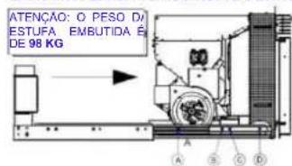
text_image
ATENÇÃO: O PESO D/ ESTUFA EMBUTIDA É DE 98 KG A B C D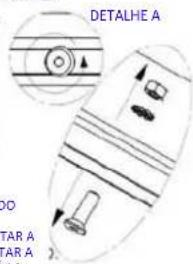
text_image
DETALHE A O STAR A STAR A 2SOLTAR OS PARAFUSOS A, B, C e D CONFORME INDICADO PARA REMOVER A ESTUFA EMBUTIDA DAS GUIAS. ACONSELHA-SE O USO DE UM CAVALETE PARA SUSTENTAR A ESTUFA UMA VEZ EXTRAÍDA. FIXAR A CHAPA E REMONTAR A ESTUFA EMBUTIDA NAS GUIAS E, ENTÃO, REPOSICIONA LA.
ESTUFA EMBUTIDA DE 11 KW
natural_image
Close-up of mechanical components with no visible text or symbolsINTERRUPTOR ON/OFF
TERMINAIS DAS SONDAS DE AMBIENTE OU DOS
RECEPTOR DO TELECOMANDO
INTERRUPTOR DE EMERGÊNCIA
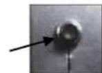
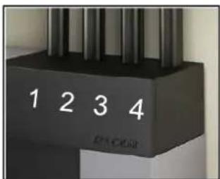
text_image
1 2 3 4 OFF COLD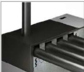
natural_image
Close-up of a black metal bracket with internal pipes and a vertical rod (no text or symbols visible)natural_image
Exterior view of a white electronic device with a screen and control panel (no visible text or symbols)LED CRONO ATIVO (L1):
| UT05 --- I" ACENDIMENTO | (ex. 7h) |
| UT06 --- I° DESLIGAMENTO | (ex. 9h) |
| UT07 --- CONFIRMAR DIASPROGRAMA 2 | (ex. DAY 1-OFF / DAY2-OFF/DAY3-OFF/DAY4-OFF/DAY5-OFF/DAY6-ON/DAY7-ON) |
| UT08 --- I" ACENDIMENTO | (ex. 18h) |
| UT09 --- I° DESLIGAMENTO | (ex. 0h) |
| UT10 --- CONFIRMAR DIAS | (ex. DAY 1-ON / DAY2-ON/DAY3-ON/DAY4-ON/DAY5-ON/DAY6-OFF/DAY7-OFF) |
CANALIZAÇÃO
text_image
Close-up of a test tube with warning label and warning symbol on a perforated panel background05.2 ELETRÓNICA COM VISOR LCD 6 CHAVES
(salamandras a pellets)
página 194 F-2 F-3
natural_image
Grid of empty circles arranged in rows and columns within a rectangular border (no text or symbols)TSET < (Tambiente - Pr43)
Menu M7 - MODO SONORO
Quando "OFF" desativa o sinal sonoro.
Menu M8 - CARGA INICIAL
natural_image
Interior view of a room with a wall-mounted cabinet and door (no visible text or symbols)Botão (P3) ON/OFF/ESC/Confirma
natural_image
Interior view of a room with a wall-mounted cabinet and door (no visible text or symbols)natural_image
Black remote control device with buttons and indicator lights (no visible text or symbols)natural_image
Close-up of a hand holding a black cylindrical object next to a red car window (no visible text or symbols)natural_image
Simple line drawing of a trash bin with two crossed lines indicating no waste or restriction (no text or symbols)natural_image
Interior view of a dark metal cabinet with an open door and a magnifying glass resting inside (no visible text or symbols)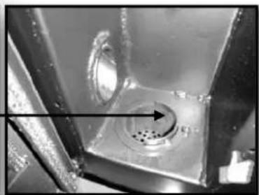
natural_image
Close-up of a circular drain with a perforated outlet, no visible text or symbols
natural_image
Interior view of a mechanical or industrial enclosure with a metal door and circular opening (no visible text or symbols)
natural_image
Close-up of a mechanical component with a central circular feature and a black arrow pointing to it (no visible text or symbols)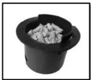
natural_image
Black top hat filled with granular material, no visible text or symbols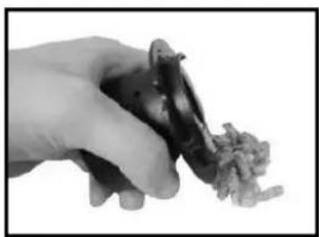
natural_image
Close-up of a hand holding a dark, crumpled object with a small amount of food or meat nearby (no text or symbols visible)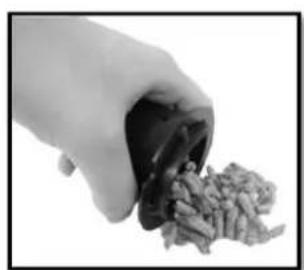
natural_image
Hand holding a small container with granular material, possibly corn kernels or grains (no text or symbols visible)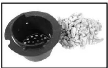
natural_image
Black-and-white photo of a small container with white dots inside and a pile of granular material beside it (no text or symbols visible)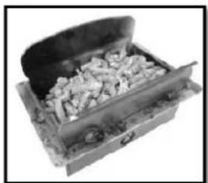
natural_image
Black-and-white photo of a wooden toolbox filled with small debris (no text or symbols visible)
natural_image
Hand holding a metal scoop filled with small white granules (no text or symbols visible)
natural_image
Hand pouring granular material into a pile of granular material (no text or symbols visible)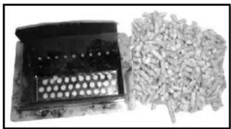
natural_image
Black-and-white photo of a vintage box with circular indentations and a pile of dried plant material beside it (no text or symbols visible)
natural_image
Close-up of a mechanical component with a plastic clip inserted, showing internal wiring and a textured surface (no visible text or symbols)
natural_image
Close-up of a hand pressing down on a mechanical component (no visible text or symbols)
natural_image
Close-up of a metal tray with a rectangular block and a perforated base, next to a circular opening (no visible text or symbols)F-1

text_image
P1 L1 D1 L2 L3 P6 1 SET 23°C OK SET P2 P3 D2 L4 L5 P4 P5F-2

text_image
P1 A3 A1 A2 P6 1 2 3 SET 81 2 00.0°C PROBIE EXHAROUST P2 P3 A4 A5 P4 P5F-3

text_image
B1 B2 8L 2 0.00°C PROBE EXHAUSTF-4

text_image
P2 L1 L4 L2 D1 L5 L3 P3 L0 P1 -1 + - 20.8°C 3F-5
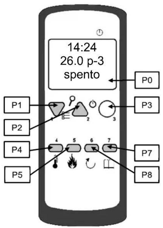
text_image
14:24 26.0 p-3 spento P0 P1 P2 P3 P4 P5 4 5 6 7 P7 P8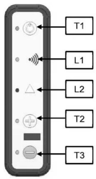
text_image
T1 L1 L2 T2 T3F-6
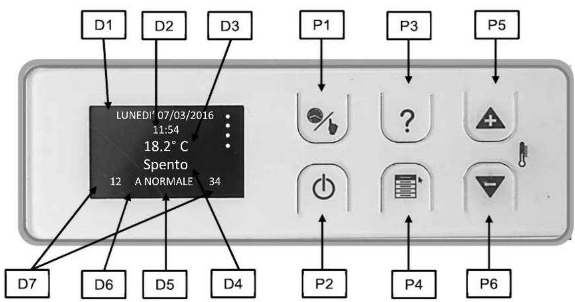
flowchart
graph TD
    A["D1"] --> B["LUNEDI '07/03/2016 11:54 18.2°C Spento 12 A NORMALE 34"]
    C["D2"] --> B
    D["D3"] --> B
    E["D4"] --> B
    F["D5"] --> B
    G["D6"] --> B
    H["D7"] --> B
    I["P1"] --> J["?"]
    K["P3"] --> L["+"]
    M["P5"] --> N["▼"]
    O["P2"] --> P["+"]
    Q["P4"] --> R["+"]
    S["P6"] --> T["+"]
F-7

flowchart
graph TD
    A["A7-a"] --> B["Processing Unit"]
    C["A7-b"] --> D["Processing Unit"]
    E["A7-c"] --> F["Processing Unit"]
    G["A7-d"] --> H["Processing Unit"]
    B --> I["Output Module 0-11"]
    D --> J["Output Module 12-13"]
    F --> K["Output Module 14-15"]
    I --> L["Segmented Block 1"]
    J --> M["Segmented Block 16"]
    K --> N["Segmented Block 17"]
    L --> O["Segmented Block 18"]
    M --> P["Segmented Block 19"]
    N --> Q["Segmented Block 20"]
    O --> R["Segmented Block 21"]
    P --> S["Segmented Block 22"]
    Q --> T["Segmented Block 23"]
    R --> U["Segmented Block 24"]
    S --> V["Segmented Block 25"]
    T --> W["Segmented Block 26"]
    U --> X["Segmented Block 27"]
    V --> Y["Segmented Block 28"]
    W --> Z["Segmented Block 29"]
    X --> AA["Segmented Block 30"]
    Y --> AB["Segmented Block 31"]
    Z --> AC["Output Module 1"]
    AA --> AD["Output Module 2"]
-
PRODUCTVEILIGHEID......pagina 236
-
ROOKKANAAL...... pagina 237
02.01 SCHOORSTEEN.... pagina 239
02.02 TREK.... pagina 239
02.03 EFFICIÊNTIE KACHEL ...... pagina 239
-
INSTRUÇÕES DE INSTALAÇÃO ...... pagina 240
-
INSTALLATIE ...... pagina 242
04.01 PELLETKACHELS.... pagina 243
04.02 PELLETKACHEL MET OVEN ...... pagina 243
04.03 INBOUW-PELLETKACHELS ...... pagina 243
04.04 PELLETFOR NUIS ...... pagina 244
04.05 PELLETFORNUIS MET OVEN ...... pagina 244
04.06 HETE-LUCHTKACHEL...... pagina 245
04.07 LUCHTDICHTE KACHELS.... pagina 246
- GEBRUIK VAN HET PRODUCT...... pagina 246
05.01 ELEKTRONICA MET 6-TOESTEN LED DISPLAY ...... pagina 246 pagina 233 F-1
(Inbouw-pelletkachels – Kanaliseerbare pelletkachel)
05.02 ELEKTRONICA MET 6-TOESTEN LCD DISPLAY ...... pagina 248 pagina 233 F-2 F-3
(Pelletkachels)
05.03 ELEKTRONICA N100 MET 3-TOETSEN DISPLAY ...... pagina 251 pagina 233 F-4
(Pelletkachels – pelletkachel met oven – Pelletfor nuis – pelletformuis met oven)
05.04 ELEKTRONICA N100 MET 6-TOETSEN DISPLAY ...... pagina 253 pagina 233 F-1 (Pelletkachels– Inbouw-pelletkachels)
05.05 ELEKTRONICA MET RADIOCONTROLE ...... pagina 255 pagina 234 F-5
(Pelletkachels)
05.06 ELEKTRONICA MET RADIOCONTROLE LCD ...... pagina 257 pagina 234 F-6
(Luchtdichte kachels)
05.07 ELEKTRONICA MET RADIOCONTROLE LCD ...... pagina 260 pagina 234 F-6
(Hete-luchtkachel)
05.08 IR-AFSTANDSBEDIENING (OPTIONEEL) ...... pagina 263
(Pelletkachels – pelletkachel met oven – Pelletfor nuis – pelletfornuis met oven – Inbouw-pelletkachels)
- REINIGING EN ONDERHOUD ...... pagina 263
- STORINGEN EN MOGELIJKE OPLOSSINGEN ...... pagina 264
- JAARLIJKS GEPLAND ONDERHOUD ...... pagina 265
- INSTALLATIE- EN KEURINGSCERTIFICAAT......pagina 266-267
- GARANTIECERTIFICAAT ......pagina 269
VEILIGHEIDSAANBEVELINGEN
natural_image
Technical drawing of stacked mechanical components with hatched areas indicating material (no text or symbols)text_image
MAX A+1/2A Atext_image
Close-up of a metallic cylindrical device with a label showing technical specifications and a central knob.02.3 EFFICIËNTIE KACHEL
natural_image
Three schematic diagrams of vertical structural elements with directional arrows indicating movement or force, no text or symbols present.natural_image
Simple line drawing of a mechanical or structural component with no visible text, numbers, or symbols.BRANDBARE
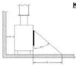
text_image
Technical diagram showing a mechanical setup with labeled dimensions and componentsNIET-BRANDBARE
KACHELS en BOILERS
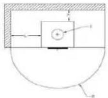
text_image
Technical diagram showing a mechanical or electrical component with labeled parts H and R, including directional arrows and a central positive symbol.BRANDBARE
NIET-BRANDBARE
HETE-LUCHTKACHEL 13,5 KW (15) SPC-15
| ACHTERWAND P = 120 | mm |
| ZIJWAND L = 300 | mm |
| VLOER F = - | mm |
| VOORZIJDE R = 100 | mm |
HETE-LUCHTKACHEL 18 KW (19,5) SPC-19,5
| ACHTERWAND P = 120 | mm |
| ZIJWAND L = 300 | mm |
| VLOER F = - | mm |
| VOORZIJDE R = 100 | mm |
PELLETKACHELS 8 KW (9) SPCT8
| ACHTERWAND P = 100 | mm |
| ZIJWAND L = 250 | mm |
| VLOER F = - | mm |
| VOORZIJDE R = | 1000 mm |
PELLETKACHELS 8 KW (9) SPCT8
| ACHTERWAND P = 100 | mm |
| ZIJWAND L = 150 | mm |
| VLOER F = - | mm |
| VOORZIJDE R = | 1000 mm |
PELLETFOR NUIS 6,7 KW (7,5) CPV-7627 (vrije installatie)
| ACHTERWAND P = 10 | mm |
| ZIJWAND L = 200 | mm |
| VLOER F = - | mm |
| VOORZIJDE R = 1000 | mm |
PELLETFOR NUIS 6,7 KW (7,5) CPV-7627 (ingekapseld in de keuken)
| ACHTERWAND P = 10 | mm |
| ZIJWAND L = 10 | mm |
| VLOER F = - | mm |
| VOORZIJDE R = 1000 | mm |
PELLETFORNUIS MET OVEN 8,6 KW (9,3) CPF-85
| ACHTERWAND P = 50 | mm |
| ZIJWAND L = 50 | mm |
| VLOER F = - | mm |
| VOORZIJDE R = 1000 | mm |
text_image
S A C B A E G H I J K Ltext_image
OVEN RS 232 VEILIGHEIDSTHE RMOSTAAT OMGEVINGSSON DETIMER
natural_image
Close-up of a black metal bracket with cylindrical components and a vertical rod (no text or symbols visible)text_image
DEKSEL PELLETS PAKKING DEKSEL PELLETS VEILIGHEIDSTHERMOSTAATLED CHRONO ACTIEF (L1):
LED OMGEVINGSTHERMOSTAAT (L4):
PROGRAMMA 1 INSCHAKELING/UITSCHAKELING (alleen's ochtends)
UT05 -UT06
ALAR HOT TEMP - Alarm oververhitting rookgassen
ALAR FAN FAIL - Alarm defect zuigventilator rookgassen
Menu M4 – SET CHRONO
Submenu M4 - 1 ENABLE CHRONO
ALARM ACTIVE ALARM FLOW – Obstructie alarm
ALARM ACTIVE HOT EXHAUST - Alarm oververhitting rookgassen
ALARM ACTIVE FAN FAILURE - Alarm defect zuigventilator rookgassen
Menu M2 - SET CHRONO
Submenu M2 - 1 CHRONO ENABLE
AL3 HOT EXHAUST - Alarm oververhitting rookgassen
AL4 FAN FAILURE - Alarm defect encoder rookgassen
Menu M2 – SET CHRONO
Submenu M2 - 1 CHRONO ENABLE
AL3 HOT EXHAUST - Alarm oververhitting rookgassen
AL4 FAN FAILURE - defect encoder rookgassen
Menu M3 - SET CHRONO
Submenu M3 - 1 ENABLE CHRONO
ALARM ACTIVE HOT EXHAUST - Alarm oververhitting rookgassen
ALARM ACTIVE FAN FAILURE - Alarm defect zuigventilator rookgassen
SET TIJDSBESTEKKEN page 234 F-7
Knop (A1) UREN
Knop (A2) NR. ZONE
Knop (A3) DAG
Knop (A4) KOPIEER
Knop (A5) LIJMEN
Knop (A6) VERLATEN
Knop (A7) VERMOGEN
SET TIJDSBESTEKKEN page 234 F-7
Niveau (A7-a) OFF-uit
Niveau (A7-b) ECONOMY
Niveau (A7-c) NORMAL
Niveau (A7-d) COMFORT
SET TIJDSBESTEKKEN page 234 F-7
Knop (A1) UREN
Knop (A2) NR. ZONE
Knop (A3) DAG
Knop (A4) KOPIEER
Knop (A5) LIJMEN
Knop (A6) VERLATEN
Knop (A7) VERMOGEN
SET TIJDSBESTEKKEN page 234 F-7
Niveau (A7-a) OFF
Niveau (A7-b) ECONOMY
Niveau (A7-c) NORMAL
Niveau (A7-d) COMFORT
Instellingen van de maximale vermogensniveaus
natural_image
Black remote control device with four buttons and a red indicator (no visible text or symbols)06. REINIGING EN ONDERHOUD
ALGEMENE BESCHOUWINGEN
natural_image
Close-up of a hand using a tool to clean or repair a black plastic component on a red car (no visible text or symbols)Adres: ____ Postcode: ____
Stad:
Tel.:
Adres: ____ Postcode: ____
Stad:
Tel.:
natural_image
Interior view of a dark metal safe with a magnifying glass resting inside (no visible text or symbols)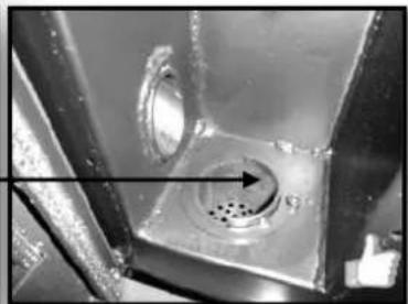
natural_image
Close-up of a metal square drain with a circular vent and a perforated outlet, showing a black arrow pointing to the outlet (no text or symbols visible)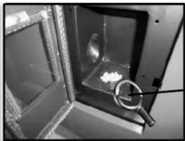
natural_image
Close-up of a metallic door with a handle and internal components (no visible text or symbols)
natural_image
Close-up of a mechanical component with a central circular feature and an arrow pointing to it (no visible text or symbols)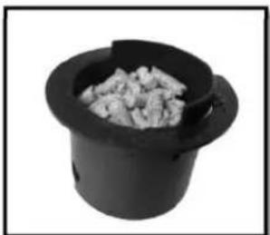
natural_image
Black top hat filled with small white granular material (no text or symbols visible)
natural_image
Hand holding a small object with textured surface, possibly food or material (no visible text or symbols)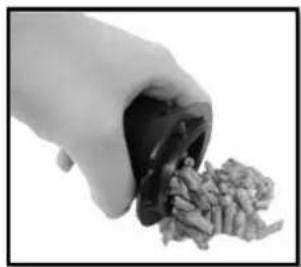
natural_image
Hand holding a container pouring granular material (no text or symbols visible)
natural_image
Black-and-white photo showing a dark container with white dots inside and a pile of dried plant material beside it (no text or symbols visible)
natural_image
Black-and-white photo of a wooden toolbox containing rubble (no text or symbols visible)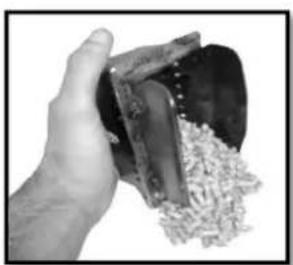
natural_image
Hand holding a metal tool with scattered debris, no visible text or symbols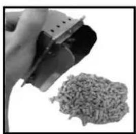
natural_image
Hand pouring granular material from a container onto a pile of granular material (no text or symbols visible)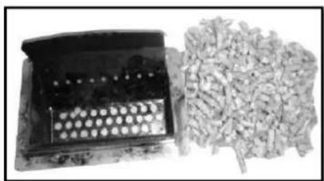
natural_image
Black-and-white photo of an open notebook with a grid of small objects beside it, alongside a pile of dried plant material (no text or symbols visible)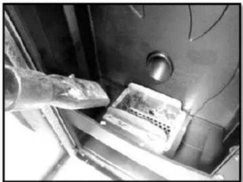
natural_image
Close-up of a mechanical component with a metallic tool inserted, showing internal wiring and a small inset device (no visible text or symbols)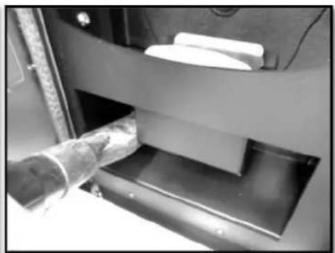
natural_image
Close-up of a mechanical component with a hand inserting a cable into a housing (no visible text or symbols)
natural_image
Close-up of a metal tray with a rectangular block and a perforated base, next to a circular opening (no visible text or symbols)F-1

text_image
P1 L1 D1 L2 L3 P6 1 SET 23°C OK SET P2 P3 D2 L4 L5 P4 P5F-2

text_image
P1 A3 A1 A2 P6 1 2 3 SET 81 2 00.0°C PROJEC EXHPOUST P2 P3 A4 A5 P4 P5F-3
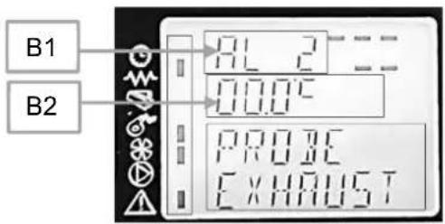
text_image
B1 B2 8L 2 0.00°C PROJEC EXHAUSTF-4
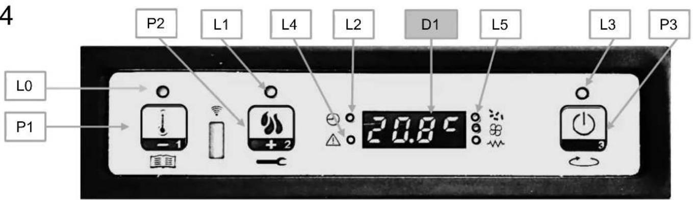
text_image
P2 L1 L4 L2 D1 L5 L3 P3 L0 P1 -1 + - 20.8°C 3
F-5

text_image
14:24 26.0 p-3 slukket P0 P3 P1 P2 P4 P5 P3 4 5 6 7 P7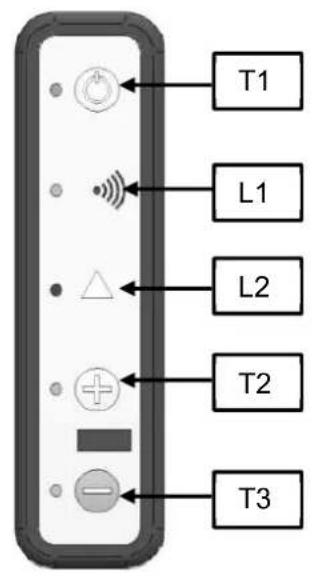
text_image
T1 L1 L2 T2 T3F-6
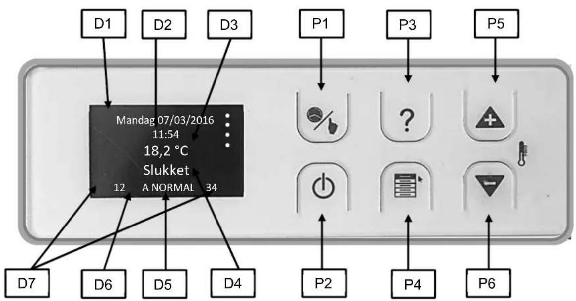
flowchart
graph TD
    D1 --> A["Mandag 07/03/2016 11:54, 18,2 °C Slukket 12 A NORMAL 34"]
    D2 --> A
    D3 --> A
    D4 --> A
    D5 --> A
    D6 --> A
    D7 --> A
    P1 --> B["?"]
    P3 --> C["+"]
    P5 --> D["+"]
    P2 --> E["+"]
    P4 --> F["-"]
    P6 --> G["-"]
F-7
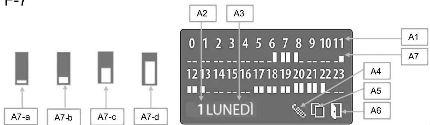
flowchart
graph TD
    A["A7-a"] --> B["Processing Block"]
    C["A7-b"] --> D["Processing Block"]
    E["A7-c"] --> F["Processing Block"]
    G["A7-d"] --> H["Processing Block"]
    B --> I["Output Block 0-11"]
    D --> J["Output Block 12-16"]
    F --> K["Output Block 17-23"]
    I --> L["Output Block 10-11"]
    J --> M["Output Block 14-18"]
    K --> N["Output Block 19-22"]
    L --> O["Output Block 23"]
    M --> P["Output Block 22"]
    N --> Q["Output Block 23"]
    O --> R["Output Block 22"]
    P --> S["Output Block 23"]
    Q --> T["Output Block 22"]
    R --> U["Output Block 23"]
    S --> V["Output Block 22"]
    T --> W["Output Block 23"]

-
PRODUKTSIKKERHED......side 275
-
TRÆKKANAL......side 276
02.01 SKORSTEN......side 278
02.02 TRÆK......side 278
02.03 OVNENS EFFEKTIVITET ....side 278
-
ADVARSLER OG INSTALLATION......side 279
-
INSTALLATION side 281
04.01 TRÆPILLEOVN......side 281
04.02 TRÆPILLEOVN MED OVN......side 282
04.03 TRÆPILLEINDSATS side 282
04.04 TRÆPILLEKOMFUR ......side 283
04.05 TRÆPILLEKOMFUR MED OVN......side 283
04.06 LUFTKEDEL side 284
04.07 LUFTTÆTTE OVNE ....side 284
- BRUG AF PRODUKTET ...... side 285
05.01 ELEKTRONIK MED LED DISPLAY 6 KNAPPER ....side 285 side 272 F-1
(Træpilleindsats – kanaliseret træpilleovn)
05.02 ELEKTRONIK MED DISPLAY LCD 6 KNAPPER....side 287 side 272 F-2 F-3 (Træpilleovn)
05.03 ELEKTRONIK MED LED DISPLAY 3 KNAPPER Nr. 100....side 289 side 272 F-4
(Træpilleovn – træpilleovn med ovn – træpillekomfur – træpillekomfur med ovn)
05.04 ELEKTRONIK MED LED DISPLAY 6 KNAPPER Nr. 100......side 291 side 272 F-1 (Træpilleovn– Træpilleindsats)
05.05 ELEKTRONIK MED RADIOSTYRING......side 293 side 273 F-5
(Træpilleovn)
05.06 ELEKTRONIK MED LCD RADIOSTYRING ....side 295 side 273 F-6
(Lufttætte ovne)
05.07 ELEKTRONIK MED LCD RADIOSTYRING ....side 298 side 273 F-6
(Luftkedel)
05.08 IR FJERNSTYRING (EKSTRAUDSTYR ....side 300
(Træpilleovn – træpilleovn med ovn – træpillekomfur – træpillekomfur med ovn – Træpilleindsats)
- RENG∅RING OG VEDLIGEHOLDELSE side 300
- ANOMALIER OG MULIGE L∅SNINGER.....side 301
- PLANLAGT ARLIG VEDLIGEHOLDELSE ...... side 302
- INSTALLATIONS- OG EFTERSYNSCERTIFIKAT ......side 303 - 304
- GARANTIBEVIS ......side 306
SIKKERHEDSADVARSLER
text_image
MAX A+1/2A Anatural_image
Close-up of a metallic cylindrical industrial pressure vessel with a central knob and control knob (no visible text or symbols)02.3 OVNENS EFFEKTIVITET
natural_image
Three technical diagrams showing vertical structural connections with arrows and components, no text or symbols present.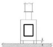
natural_image
Simple line drawing of a mechanical setup with a rectangular block and a top fixture, no text or symbols present.OVNE OG KEDLER
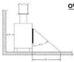
text_image
OV 45°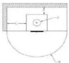
text_image
Technical diagram showing a mechanical or electrical component with labeled parts and directional arrowsBRANDFARLIG
IKKE BRANDFARLIG
BRANDFARLIG
IKKE BRANDFARLIG
LUFTKEDEL13,5 KW (15) SPC-15
| BAGVÆG P = 120 | mm |
| SIDEVÆG L = 300 | mm |
| GULV F = - | mm |
| FRONT R = 100 | mm |
LUFTKEDEL 13,5 KW (15) SPC-15
| BAGVÆG P = 120 | mm |
| SIDEVÆG L = 200 | mm |
| GULV F = - | mm |
| FRONT R = 100 | mm |
LUFTTÆT OVN SLIM 7 KW (8) SPE7
| BAGVÆG P = 50 | mm |
| SIDEVÆG L = 300 | mm |
| GULV F = - | mm |
| FRONT R = 1000 | mm |
LUFTTÆT OVN SLIM 7 KW (8) SPE7
| BAGVÆG P = 50 | mm |
| SIDEVÆG L = 200 | mm |
| GULV F = - | mm |
| FRONT R = 1000 | mm |
LUFTKEDEL 18 KW (19,5) SPC-19,5
| BAGVÆG P = 120 | mm |
| SIDEVÆG L = 300 | mm |
| GULV F = - | mm |
| FRONT R = 100 | mm |
LUFTKEDEL 18 KW (19,5) SPC-19,5
| BAGV/EG P = 120 | mm |
| SIDEV/EG L = 200 | mm |
| GULV F = - | mm |
| FRONT R = 100 | mm |
TRÆPILLEOVN 5 KW (6) SP6
| BAGVÆG P = 250 | mm |
| SIDEVÆG L = 300 | mm |
| GULV F = - | mm |
| FRONT R = 1000 | mm |
TRÆPILLEOVN 5 KW (6) SP6
| BAGV/EG P = 250 | mm |
| SIDEV/EG L = 200 | mm |
| GULV F = - | mm |
| FRONT R = 1000 | mm |
LUFTKEDEL 18,5 KW (20,5) GP-20
| BAGVÆG P = 80 | mm |
| SIDEVÆG L = 200 | mm |
| GULV F = - | mm |
| FRONT R = 100 | mm |
LUFTKEDEL 18,5 KW (20,5) GP-20
| BAGVÆG P = 80 | mm |
| SIDEVÆG L = 100 | mm |
| GULV F = - | mm |
| FRONT R = 100 | mm |
TRÆPILLEOVN 8 KW (9) SPCT8
| BAGVÆG P = 100 | mm |
| SIDEVÆG L = 250 | mm |
| GULV F = - | mm |
| FRONT R = 1000 | mm |
TRÆPILLEOVN 8 KW (9) SPCT8
| BAGVÆG P = 100 | mm |
| SIDEVÆG L = 150 | mm |
| GULV F = - | mm |
| FRONT R = 1000 | mm |
TRÆPILLEKOMFUR 6,7 KW (7,5) CPV-7627
(Fri installation)
| BAGVÆG P = 10 | mm |
| SIDEVÆG L = 200 | mm |
| GULV F = - | mm |
| FRONT R = 1000 | mm |
TRÆPILLEKOMFUR 6,7 KW (7,5) CPV-7627
(Fri installation)
| BAGVÆG P = 10 | mm |
| SIDEVÆG L = 100 | mm |
| GULV F = - | mm |
| FRONT R = 1000 | mm |
TRÆPILLEOVN 7,5 KW (8,6) SPSV
| BAGVÆG P = 200 | mm |
| SIDEVÆG L = 200 | mm |
| GULV F = - | mm |
| FRONT R = 1000 | mm |
TRÆPILLEOVN 7,5 KW (8,6) SPSV
| BAGVÆG P = 150 | mm |
| SIDEVÆG L = 150 | mm |
| GULV F = - | mm |
| FRONT R = 1000 | mm |
| BAGV/EG P = 50 | mm |
| SIDEV/EG L = 150 | mm |
| GULV F = - | mm |
| FRONT R = 1000 | mm |
LUFTTÆT OVN SLIM 8,5 KW (9,5) SPE8,5
| BAGVÆG P = 50 | mm |
| SIDEVÆG L = 50 | mm |
| GULV F = - | mm |
| FRONT R = 1000 | mm |
TRÆPILLEOVN CAN 14 KW (15) SPV-M13
| BAGVÆG P = 200 | mm |
| SIDEVÆG L = 300 | mm |
| GULV F = - | mm |
| FRONT R = 1000 | mm |
TRÆPILLEOVN CAN 14 KW (15) SPV-M13
| BAGVÆG P = 200 | mm |
| SIDEVÆG L = 200 | mm |
| GULV F = - | mm |
| FRONT R = 1000 | mm |
TRÆPILLEOVN MED OVN 7,5 KW (8,5) SPF8.5
| BAGV/EG P = 200 | mm |
| SIDEV/EG L = 300 | mm |
| GULV F = - | mm |
| FRONT R = 1000 | mm |
TRÆPILLEOVN MED OVN 7,5 KW (8,5) SPF8,5
| BAGV/EG P = 200 | mm |
| SIDEV/EG L = 200 | mm |
| GULV F = - | mm |
| FRONT R = 1000 | mm |
| BAGV/EG P = 200 | mm |
| SIDEV/EG L = 200 | mm |
| GULV F = - | mm |
| FRONT R = 1000 | mm |
| BAGV/EG P = 200 | mm |
| SIDEV/EG L = 200 | mm |
| GULV F = - | mm |
| FRONT R = 1000 | mm |
TRÆPILLEOVN SLIM CAN 9,3 KW (10,5) SPCS9
| BAGVÆG P = 50 | mm |
| SIDEVÆG L = 150 | mm |
| GULV F = - | mm |
| FRONT R = 1000 | mm |
text_image
Technical diagram showing cross-sectional views and labeled components of a mechanical or architectural component, with annotations A, B, C, D, E, F.Kun LUFTTÆT OVN
text_image
VENTILATIONSLUFT UDGANG PLADE I STÄL ELLER GLAS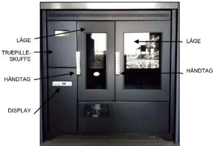
text_image
LÄGE TRÆPILLE- SKUFFE HÄNDTAG DISPLAY LÄGE HÄNDTAGnatural_image
Close-up of a mechanical component with cylindrical and rectangular parts, no visible text or symbolsCRONO LED AKTIVEREDE (L1):
BETYDNING | DISPLAY D1
| DAY 1 - Mandag | DAY 2 - Tirsdag | DAY 3 - Onsdag | DAY 4 - Torsdag | DAY 5 - Fredag | DAY 6 - Lørdag | DAY 7 - Søndag | OFF - Kronotermostat frakoblet |
UT01
text_image
Close-up of a panel with a warning label and a small object, likely indicating a hazard or safety warning.ALAR COOL FIRE - Manglende netspænding alarm
natural_image
Grid of empty circles arranged in a uniform pattern within a rectangular border (no text or symbols)
natural_image
Grid of identical circular patterns arranged in rows and columns (no text or symbols)Menu M4 – SET CHRONO
Undermenu M4 - 1 ENABLE CHRONO
HVAD SKER DER, HVIS ...
natural_image
Close-up of a control panel with vertical slots and a small mark (no visible text or symbols)ALARM ACTIVE FAN FAILURE - Røgudsugningsventilator fejlalarm
Menu M2 – SET CHRONO
Undermenu M2 - 1 CHRONO ENABLE
Menu M2 – SET CHRONO
Undermenu M2 - 1 CHRONO ENABLE
KNAP (P1) - Reducer:
Menu M3 – SET CHRONO
Undermenu M3 - 1 ENABLE CHRONO
HVAD SKER DER, HVIS ...
Strømmangel (black-out)
natural_image
Close-up of a metallic panel with vertical slots and a small mark (no visible text or symbols)CERCA CAMPO
SET TIDSINTERVALLER Side 273 F-7
Knap (A1) TIMER
Knap (A2) ZONENR.
Knap (A3) DAG
Knap (A4) KOPIER
Knap (A5) SÆT IND
Knap (A6) GÅ UD
Knap (A7) EFFEKT
EFFEKTNIVEAUER Side 273 F-7
Niveau (A7-a) OFF
Niveau (A7-b) ECONOMY
Niveau (A7-c) NORMALE
Niveau (A7-d) COMFORT
natural_image
Black remote control device with four buttons and a red indicator lights (no visible text or symbols)06. RENG∅RING OG VEDLIGEHOLDELSE
FORUDSÆTNINGER
natural_image
Close-up of a hand using a tool to trim a dark object on a red car (no visible text or symbols)KUN TIL TRÆPILLEKOMFUR
(Teknisk support service stempel) (Teknisk support service stempel)
Dato 3. vedligeholdelse ____ / ____ / ____ Dato 4. vedligeholdelse ____ / ____ / ____
(Teknisk support service stempel) (Teknisk support service stempel)
INSTALLATIONS- OG EFTERSYNSCERTIFIKAT
KUNDE:
Sælgerens stempel:
VEJNAVN:
BY:
POSTNR.
Installatørens stempel:
PROVINS:
TLF.:
Leveringsdato:
Fornavn:
Leveringsdokument:
Efternavn:
Apparat mod.: