LayZSpa 60031 - Inflatable spa BESTWAY - Free user manual and instructions
Find the device manual for free LayZSpa 60031 BESTWAY in PDF.
| Product Type | Portable inflatable spa |
| Brand | Bestway |
| Model | LayZSpa 60031 |
| Power supply | 220-240 V ~ 50 Hz, single phase |
| Heating power | 2000 W |
| Filtration pump power | 50 W |
| Massage system power | 1200 W |
| HydroJet system power | 800 W |
| Adjustable temperature range | 20 °C to 40 °C |
| Freeze Shield™ antifreeze function | Yes, maintains between 6 °C and 10 °C |
| Energy-saving timer | Yes, adjustable from 1 to 999 hours |
| Electrical safety device | Integrated PRCD (trip at 10 mA) |
| Differential circuit breaker test | Required before each use |
| Cover material | Reinforced PVC (TriTech on some models) |
| Filtration cartridge | Included, weekly replacement recommended |
| Water chemical treatment | Recommended (chlorine or bromine) |
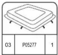
| Safety cover | Included |
| Repair kit | Patch provided for PVC repair |
| Maximum weight supported | Not specified, see manual |
| Overall dimensions | Not specified in the manual |
Frequently Asked Questions - LayZSpa 60031 BESTWAY
User questions about LayZSpa 60031 BESTWAY
0 question about this device. Answer the ones you know or ask your own.
Ask a new question about this device
Download the instructions for your Inflatable spa in PDF format for free! Find your manual LayZSpa 60031 - BESTWAY and take your electronic device back in hand. On this page are published all the documents necessary for the use of your device. LayZSpa 60031 by BESTWAY.
USER MANUAL LayZSpa 60031 BESTWAY
text_image
LAY-Z-SPA®IMPORTANT SAFETY INSTRUCTIONS pg 003
PRE-SETUP CHECK LIST pg 013
INSTALLATION pg 015
SET-UP INSTRUCTION IN WINTER pg 015
USING THE SPA pg 019
MAINTENANCE pg 022
DISASSEMBLY AND STORAGE pg 024
TROUBLESHOOTING pg 026
ERROR CODES pg 027

text_image
Visit w w b es tway corp.com/support for help WE SUGGEST NOT TO RETURN THE PRODUCT TO THE STORE QUESTIONS? PROBLEMS? MISSING PARTS? For FAQ, Manuals, Videos Or spare Parts, Please Visit bestwaycorp.com/supportIMPORTANT SAFETY INSTRUCTIONS
SAFETY INSTRUCTIONS
Carefully read, understand, and follow all information in this user manual before installing and using the spa.
IMPORTANT SAFETY INSTRUCTIONS - READ AND FOLLOW ALL INSTRUCTIONS.
WARNING:
- The spa must be supplied through an isolating transformer or supplied through a residual current device (RCD) having a rated residual operating current not exceeding 30mA.
- The spa must be connected to a grounded mains supply socket with a supply cord fitted with a plug and PRCD with a tripping current of 10mA.
- The pump must be tested before each use, to test follow the instruction of pump.
- If the supply cord is damaged, it must be replaced by the manufacturer, service agent or similarly qualified persons in order to avoid a hazard.
- To reduce the risk of electric shock, do not use extension cord to connect unit to electric supply; provide a properly located outlet.
- No part of the appliance is to be located above the bath during use.
- Parts containing live parts, except parts supplied with safety extra-low voltage not exceeding 12V, must be inaccessible to a person in spa pool; Parts incorporating electrical components, except remote control devices, must be located or fixed so that they cannot fall into the spa pool.
- The spa must be supplied by earthed power source.
- The power source on the wall of building should keep more than 4m away from pool.
- Warning: Always keep plug dry, plug in with wet plug is definitely forbidden!
- The plug shall be directly connected only to a socket-outlet of the fixed electrical installation.
- It is necessary to have the plug accessible after installation of the spa.
CAUTION: In order to avoid a hazard due to inadvertent resetting of the thermal cut-out, this appliance must not be supplied through an external switching device, such as a timer, or connected to a circuit that is regularly switched on and off by the utility.
After using your spa for 3-5 years, you should contact your local qualified maintenance technician to ensure the safety and performance of the spa. The main components, such as heating element, air blower motor and non-return valves within the electric unit should be checked and replaced (if necessary) by professional persons.
• TO AVOID ELECTRIC SHOCK, DO NOT USE THE SPA WHEN IT IS RAINING, THUNDERING OR LIGHTNING.
- Never wear your contact lenses when in your spa.
- Do not use spa during chemical maintenance.
- Extension cords can't be used.
- Don't plug or unplug the appliance if hand is wet.
• Always unplug the appliance:
- before cleaning or other maintenance
- if leave it unattended on holidays
- When the appliance will be not used for a long time, such as in the winter, the spa or pool set should be disassembled and stored indoor.
- For safety reason, only use the accessories provided or approved by the spa manufacturer.
- Do not to place the spa on slippery surface, and to make sure the surface is free of sharp object before installation.
- Never place any electrical supplies or appliance, such as a light, telephone, radio, or television, within 2m of spa.
- Caution: Read the instruction before using the appliance and installation or reassemble every time.
- Safekeeping the instruction. If instruction is missed, please contact with manufacturer or search it in website www.bestwaycorp.com
- Warning: For electric safety, a PRCD is incorporated in the power cord, if the leakage current is detected more than 10mA, the device will operate and cut-off the power supply,
in such case, please unplug and stop using the spa at once. Don't reset the product by yourself. And you must contact the local service agent to check and repair the product.
- This appliance can be used by children aged from 8 years and above and persons with reduced physical, sensory or mental capabilities or lack of experience and knowledge if they have been given supervision or instruction concerning use of the appliance in a safe way and understand the hazards involved. Children shall not play with the appliance. (For EU market)
- Cleaning and user maintenance must be performed by an adult above 18 years old who is familiar with the risk of electric shock. This appliance is not intended for use by persons (including children) with reduced physical, sensory or mental capabilities, or lack of experience and knowledge, unless they have been given supervision or instruction concerning use of the appliance by a person responsible for their safety. Children should be supervised to ensure that they do not play with the appliance. (For market other than EU)
- Water attracts children; always attach a spa cover after each use.
- Do not bury cord. Locate cord to minimize abuse from lawn mowers, hedge trimmers, and other equipment.
- DANGER - Risk of Accidental Drowning (especially children under 5 years). Caution shall be exercised to prevent unauthorized access to the spa by children. This can be reached by adult supervisor securing the means of access or installing a safety protection device to the spa. To avoid accidents during spa use, ensure that children are kept under constant adult supervision.
- DANGER - Risk of Injury. The suction fittings in this spa are sized to match the specific water flow created by the pump. Should the need arise to replace the suction fittings or the pump, be sure that the flow rates are compatible. Never operate the spa if the suction fittings are broken or missing. Never replace a suction fitting with one rated less than the flow rate marked on the original suction fitting.
- RISK OF INJURY. Never operate spa if inlet / outlet pipes are
broken or missing. Never attempt to replace the inlet / outlet pipes. Always consult your local Aftersales centre.
- RISK OF ELECTRIC SHOCK. Install at least 2m from all metal surfaces.
- RISK OF ELECTRIC SHOCK. Never operate any electrical appliance when in your spa or when your body is wet. Never place any electric appliance, such as a light, telephone, radio, or television, within 2m of spa.
- During pregnancy, soaking in hot water may cause damage to the fetus. Limit use to 10 minutes at a time.
• TO REDUCE THE RISK OF INJURY:
A. The water in a spa should never exceed 40^ C ( 104^ F). Water temperature between 38^ C ( 100^ F) and 40^ C ( 104^ F) is considered safe and comfortable for a healthy adult. Lower water temperatures are recommended for young children and when spa use exceeds 10 minutes.
B. Since excessive water temperatures have a high potential for causing fetal damage during the early months of pregnancy, pregnant or possibly pregnant women should limit spa water temperature to 38^ C ( 100^ F).
C. Before entering a spa, the user should measure the water temperature with an accurate thermometer since the tolerance of water temperature regulating device varies.
D. The use of alcohol, drugs, or medication before or during spa use may lead to unconsciousness with the possibility of drowning.
E. Obese persons and persons with a history of heart disease, low or high blood pressure, circulatory system problems, or diabetes should consult a physician before using a spa.
F. Persons using medication should consult a physician before using a spa since some medication may induce drowsiness while other medication may affect heart rate, blood pressure, and circulation.
G. Avoid putting the head under water at all times.
H. Avoid swallowing spa water.
• TO REDUCE THE RISK OF INJURY: Never pour water with a temperature higher than 40^ C ( 104^ F) into the spa pool directly.
- The use of alcohol, drugs, or medication can greatly increase the risk of fatal hyperthermia. Hyperthermia occurs when the internal temperature of the body reaches a level that is several degrees above the normal body temperature of 37°C (98.6°F). The symptoms of hyperthermia include an increase in the internal temperature of the body, dizziness, lethargy, drowsiness, and fainting. The effects of hyperthermia include failure to perceive heat; failure to recognize the need to exit spa or hot tub; unawareness of impending hazard; fetal damage in pregnant women; physical inability to exit the spa or hot tub; and unconsciousness resulting in the danger of drowning.
- Electric installations should follow national wiring rules, consult a qualified electrician with any questions.
• These warnings, instructions, and safety guidelines address some common risks of water recreation, but they cannot cover all risks and dangers in all cases. Always use caution, common sense, and good judgment when enjoying any water activity. Retain this information for future use. In addition, the following information can be supplied depending on the spa type:
Non Swimmers safety
- Continuous, active, and vigilant supervision of weak swimmers and non-swimmers especially in exercise spas, by a competent adult is required at all times (remembering that children under five years of age are at the highest risk of drowning).
- Designate a competent adult to supervise the spa each time it is being used.
- Weak swimmers or non-swimmers should wear personal protection equipment, especially when using the exercise spa.
- When the spa is not in use, or unsupervised, remove all toys from the spa and its surrounding area to avoid attracting children to the spa.
Safety devices
- A safety cover or other safety protection device shall be used, or all doors and windows (where applicable) shall be secured to prevent unauthorized access to the spa.
- Barriers, covers, alarms, or similar safety devices are helpful
aids, but they are not substitutes for continuous and competent adult supervision.
Safety equipment
- It is recommended to keep rescue equipment (e.g. a ring buoy) by the spa (if appropriate).
- Keep a working phone and a list of emergency phone numbers near the spa.
Safe use of the spa
- Encourage all users especially children to learn how to swim.
- Learn Basic Life Support (Cardiopulmonary Resuscitation - CPR) and refresh this knowledge regularly. This can make a life-saving difference in the event of an emergency.
- Instruct all spa users, including children, what to do in case of an emergency.
- Never dive into any shallow body of water. This can lead to serious injury or death.
- Do not use the spa when using alcohol or medication that may impair the bather's ability to safely use the spa.
- When covers are used, remove them completely from the water surface before entering the spa.
- Protect spa occupants from water related illnesses by advising them to keep water treated and practicing good hygiene. Consult the water treatment guidelines in the user's manual.
- Store chemicals out of the reach of children.
- Use the signage provided on the spa or within 2 000 mm of the spa in a prominent visible position.
- Removable ladders, when removed, shall be stored safely where children cannot climb on it.
CONSULT YOUR PHYSICIAN FOR RECOMMENDATIONS. CAUTION:
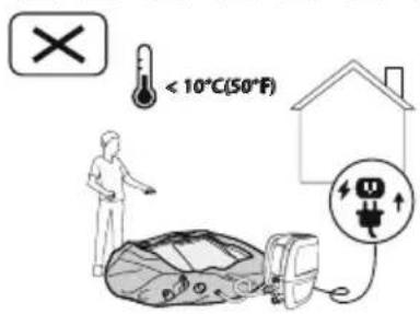
- We strongly recommend not to unfold and inflate the spa if the ambient temperature is below 15°C(59°F). We suggest inflating the spa indoors, and then continuing set up outdoors. If the outdoor temperature is lower than 6°C(42.8°F), the spa heater must always be on. In this mode, the Freeze Shield™ system can keep the internal temperature between 6°C(42.8°F) and 10°C(50°F) to prevent damage, such as water freezing in the
pipes or the circulation system.
Important: If the Freeze Shield™ system isn't working, alarms will pop up on the spa. Be sure to check the status of your spa if the outdoor temperature is below 6°C(42.8°F). In case of a long-term absence from home when there is a risk of temperatures falling below 6°C(42.8°F), we strongly suggest disassembling the spa and storing it following the storage procedure.
- Do not use the spa alone.
- People with infectious diseases should not use a spa.
- Do not use the spa immediately following strenuous exercise.
• Always enter and exit the spa slowly and cautiously. Wet surfaces are slippery.
- To avoid damage to the pump, the spa must never be operated unless the spa is filled with water.
- Immediately leave spa if the user feels uncomfortable or sleepy.
- Never add water to chemicals. Always add chemicals to water to avoid strong fumes or violent reactions that may result in hazardous chemical spray.
- Regarding the information pertaining to cleaning, maintenance of water, and disposal of water, please see section "MAINTENANCE".
- Regarding the information pertaining to the installation, thanks to refer to the below paragraph of the manual.
NOTE:
- Please examine equipment before use. Notify Bestway at the customer service address listed on this manual for any damaged or missing parts at the time of purchase. Verify that the equipment components represent the models that you had intended to purchase.
- This product is not intended for commercial use.
SAVE THESE INSTRUCTIONS
SELECTED LOCATION
Indoor and outdoor & above ground & portable wiring & portable spa
WARNING: The selected location has to be able to support of supporting the expected load.
WARNING: An adequate drainage system has to be provided to deal with overflow water for both indoor and outdoor installations.
- Always keep the spa cover on to minimize heat loss during heating of the spa between uses (but not while it is being used). Ensure the cover is fitted tightly, as per instructions to maximize insulation. It shall be recommended that the cover, when not in use, should be kept off the ground to retain its cleanliness (particularly the surface in close proximity to the water spa water surface). The cover should be stored in an appropriate location, where it cannot be damaged, or cause damage.
- Check the set water temperature and consider lowering it for the times when the spa will typically not be in use.
- Depending on external conditions, consider turning off the heater entirely if not using the spa for an extended period of time (where the spa provides this option, but still maintains residual disinfection/pH-values).
- It is recommended to use an insulating ground cloth underneath the spa to minimize heat loss through the bottom of the spa.
- Maintain clean filters to preserve appropriate working conditions for the pump and avoid unnecessary water replacement and re-heating.
- Keep the spa away from the rest area to minimize noise disturbance.
- Recommended to ask a qualified contractor or a structural engineer to verify if the support material is strong enough to support the maximum design load of the spa, spa water and bathers. Read the filled weight information on the
package.
- Please keep at least 1m clearance around the spa.
- Consult your local government authority for water regulations related to convenient water supply for filling the spa.
- Recommended to consult experts and/or local authorities to apply local or national laws/regulations relating to childproof fencing, safety barriers, lighting, and other safety requirements.
- Do not put the cover on the ground or any other dirty surface when not in place on the spa.
- When the spa is being used, the cover should be placed in a clean, dry area, otherwise it can pick up dirt and bacteria. Covers should not be put on wooden tables or wooden decking because of the risk of bleaching the wood. A cover lifter, or similar device, is useful for ensuring that the cover does not come into contact with the ground. A cover lifter is strongly recommended for spas in rental settings.
IMPORTANT: Because of the combined weight of the Lay-Z-Spa, water, and users, it is extremely important that the base where the Lay-Z-Spa is installed is smooth, flat, level and capable of uniformly supporting the weight for the entire time the Lay-Z-Spa is installed (not on the carpet or other similar material). If the Lay-Z-Spa is placed on a surface, which does not meet these requirements, any damage caused by improper support is not covered under the manufacturer's warranty. It is the responsibility of the Lay-Z-Spa owner to assure the integrity of the site at all times.
1. Indoor Installation:
Be aware of special requirements if you install the spa indoors.
- Humidity is a natural side effect with Lay-Z-Spa installation. Determine the effects of airborne moisture on exposed wood, paper, etc. in the proposed location. To minimize
these effects it is best to provide plenty of ventilation to the selected area. An architect can help determine if more ventilation is needed.
- Consult your local government authority for installation regulations.
- Keep suitable air treatment in the spa chamber (ventilation and dehumidification) regularly to preserve the bathers' safety and comfort.
- Do not to install the spa on carpet or other floor materials (e.g. untreated cork, timber or other porous materials) that promote or harbour moisture and bacteria, or that could be affected by water treatment chemicals used in the spa.
- Empty the spa before remove it from the chamber or building.
2. Outdoor Installation:
- During filling, draining or when in use, water may flow out of the spa. Therefore the Lay-Z-Spa should be installed near a floor drain.
- Do not leave the spa's surface exposed to direct sunlight for long periods of time.
- Consult your local professional installers for environmental conditions, such as ground water and risk of frost.
- Recommended to protecting the spa from direct sunlight exposure by a cover when not in use.
PRE-SETUP CHECK LIST
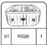
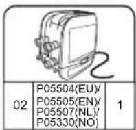
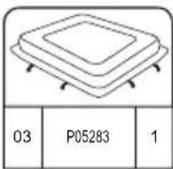
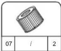
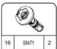
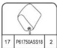
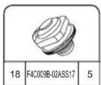
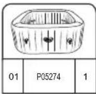
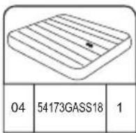
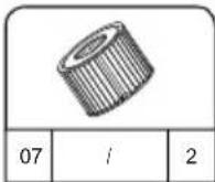
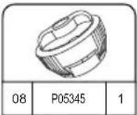
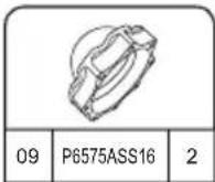
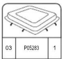
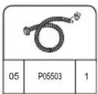
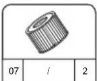
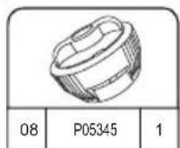
PARTS CHECKS
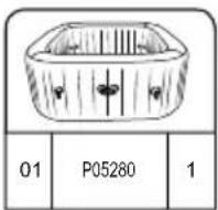
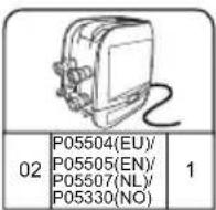
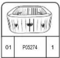
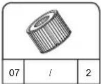
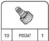
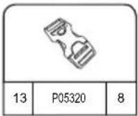
Please examine equipment before use. Notify Bestway® customer service of any damaged or missing parts at the time of purchase. Verify that the equipment components represent the model that you had intended to purchase. For reference please use the diagrams below.
natural_image
Abstract geometric diagram with overlapping planes and shaded regions (no text or symbols)MALDIVES HYDROJET PRO S200102 (60033)
— 2.01 m x 2.01 m x 80 cm / 79" x 79" x 31.5"

5 - 7 1-1.5°C/h

2-3°F/h

1,325 L/h
350 gal/h

1.2PSI 0.08Bar

1050 L
277 gal

1118 kg
2,465 Lb


HAWAII HYDROJET PRO S200102 (60031)
.— 1.80 m x 1.80 m x 71 cm / 71" x 71" x 28"

4 - 6 1.5-2°C/h

3-4°F/h

1,325 L/h
350 gal/h

1.2PSI 0.08Bar

795 L
210 gal

848 kg 1,869 Lb


INSTALLATION

SET-UP
INSTRUCTION
IN WINTER

text_image
< 10°C(50°F)
text_image
> 15°C(59°F) > 15°C(59°F)It is important to follow these suggestions if you are setting up the spa during the winter period. This will prevent damage to the PVC material and extend the life of your product drastically.
- If the ambient temperature is below 10^(50^) , we suggest keeping the package indoor where the temperature is above 15^(59^) for at least 2h before inflation. This will make the spa liner more flexible and easier to set up.
- Open the package in the same room where the temperature is above 15^ C(59^ F) , and inflate the spa using the spa heater.
- Position the spa liner outdoor in the desired position, connect the spa heater and fill with water.
Important: The water temperature used to fill the spa must be above 6^ C( 42.8^ F), otherwise when you begin to operate with the spa heater, the E03 alarm will appear.
Important: If the Freeze Shield™ system isn't working, alarms will pop up on the spa. Be sure to check the status of your spa if the outdoor temperature is below 6°C(42.8°F). In case of a long-term absence from home when there is a risk of temperatures falling below 6°C(42.8°F), we strongly suggest disassembling the spa and storing it following the storage procedure. When you assemble the spa, the automatic warm function will turn on. In this condition, the spa can be used when the temperature is lower than 6°C(42.8°F).
1 2 3
natural_image
Simple line drawing of a folded fabric or material (no text or symbols)
natural_image
Diagram of a cable being inserted into an electrical device (no text or symbols present)
natural_image
Line drawing of an electrical plug device connected to a circular icon showing a plug with lightning and up arrows (no text or symbols)4

flowchart
graph TD
    A["Device Inserted"] --> B["Measurement Equipment"]
    B --> C["Control Panel Display"]
    C --> D["Digital Display Control"]
    D --> E["Time Measurement"]
    E --> F["5 min. Time"]

5 min.
text_image
Maldives A B C5.25.1

natural_image
Diagram showing two rectangular blocks with a curved arrow pointing downward from one to the other (no text or symbols)6

text_image
Diagram illustrating a medical procedure for using a pressure monitor, showing step-by-step instructions and validation outcomes.7
natural_image
Line drawing of a handheld electronic device with hoses and connectors, no text or symbols present8

natural_image
Line drawing of a portable device with a hand panel and a walkie-talkie, showing no text or symbols.9

natural_image
Diagram of a mechanical component with internal gears and a magnified inset showing internal structure (no text or labels)10

natural_image
Diagram showing a device emitting a surface with a magnified inset of a grid-patterned object (no text or symbols)11

text_image
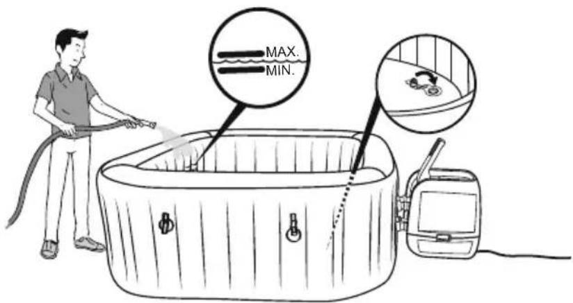
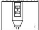
MAX. MIN.16
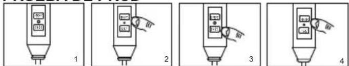
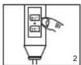
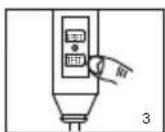
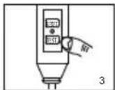
PRCD Test

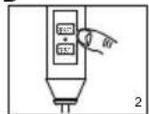
NOTE: Drawings for illustration purpose only. May not reflect actual product. Not to scale.
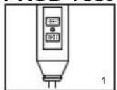
- Insert the plug.
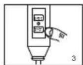
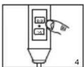
- Press the "RESET" button, the indicator light turns on.
- Press the "TEST" button, the indicator light turns off.
- Press the "RESET" button, the indicator light turns on.
- Press the "On/Off" button for 2 seconds, your pump is ready to use.
text_image
8.8.6 °C °F 6/6 0 +/-WARNING: Before inserting plug into a power outlet, make sure the current rate of the power outlet is suitable for the pump.
WARNING: Using an extension lead or multi plug adaptor with the spa heater can cause the plug to overheat, causing damage to the equipment and surrounding items. The spa is a class I electrical appliance and must be connected directly to a grounded socket. It is recommended to only use a socket which is resistant to humidity and capable of high power loading. Regularly check the plug and socket for signs of damage before using the spa – do not use the spa if the plug or socket is damaged. If you are unsure about the quality of the electrical supply, please consult a qualified electrician before use.
WARNING: The PRCD plug must be tested before each use to avoid risk of electric shock.
WARNING: Do not use the pump if this test fails. For assistance, please visit the support section on our website, www.bestwaycorp.com.
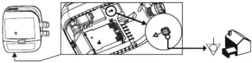
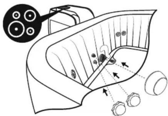
SPA PUMP EQUIPOTENTIAL BONDING TERMINAL
It is recommended to arrange for a qualified electrician to connect the spa pump to an equipotential bonding terminal using a minimum 2.5mm^2 solid copper conductor.
text_image
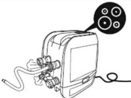
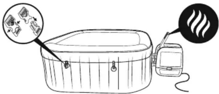
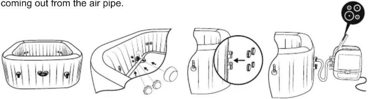
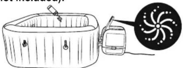
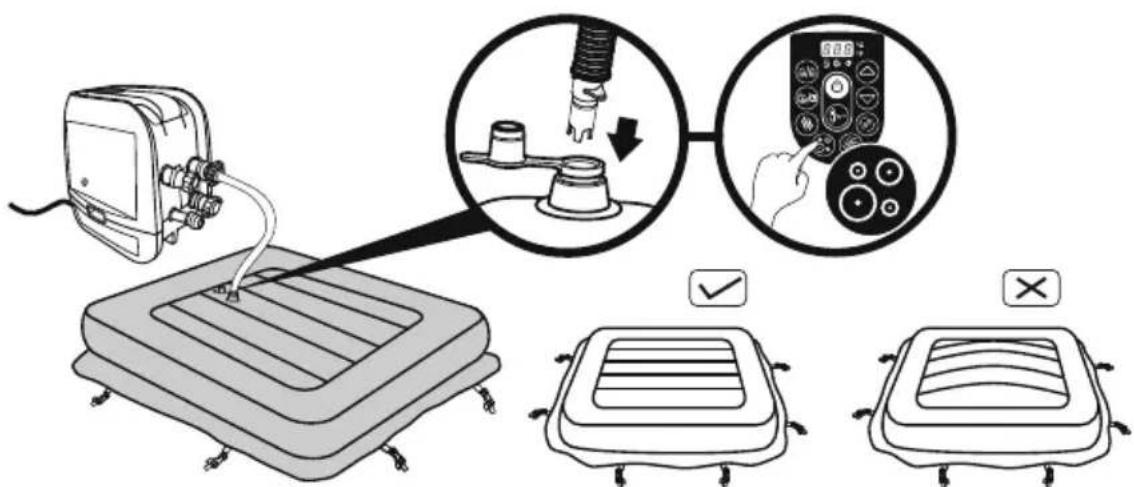
Technical diagram showing a device's internal components and a close-up of a component with a magnified view.When inflating, you will notice that air will be expelled from the area where the air hose connects to the pump, this is normal for technique requirements.
Important: Don't cover the holes on the base of the inflation hose. This operation will over inflate the liner and damage the structure.
Do not use an air compressor to inflate the pool.
Do not drag the pool on rough ground as this may cause damage to the pool liner. Inflation time for reference only.
natural_image
Line drawing of a medical or electrical device with hoses and connectors, connected to a cable (no text or symbols)USING THE SPA
natural_image
Technical line drawing of a mechanical device with no visible text or symbols
natural_image
Technical line drawing of a mechanical device with no visible text or symbols
text_image
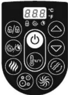
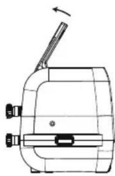
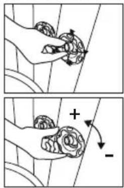
A B C D 8.8.8 °C °F E F G H I JAdjustment of Jet Nozzle
text_image
Diagram illustrating hand manipulation of a flower with directional arrows and polarity signs
A. LOCK/UNLOCK BUTTON: The pump has a 5-minute auto-lock, this light will turn on. To lock or unlock the pump, place a finger over the lock/unlock button for 3 seconds.

B. POWER-SAVING TIMER BUTTON: Designed to help avoid wasting power by setting the time and duration of the heating cycle for the spa. This way, you can enjoy your spa at the time you desire, without needing to leave the heater on at all times.
STEP 1: Set the heating duration
- Press the 🔒 button unit the Ⓞ LED starts to flash.
- Press the 🔒 or ⬇ button to adjust the heating duration (From 1-999 hours).
- Press the button again to confirm the heating duration.
STEP 2: Set the number of hours FROM NOW when the heater will activate
- After setting the heating duration, the LED starts to flash.
- Press the ▶ or ▽ button to adjust the hours until time of activation (From 0-999 hours).
- Press 📄 button again or simply touch nothing for 10 seconds to confirm the setting. The ⚙ LED will light steadily, and the countdown to heater activation will begin.
To modify the timer settings: Press the ⏻ button and use the ⏻ or ⏻ button to adjust. Cancel the setting: Press the ⏻ button for 2 seconds.
NOTE: After setting, the screen flashes the current temperature and time alternately. NOTE: Timer adjustment (amount of time with the heater ON) may be set from 1 to 999 hours; Reservation time adjustment (the number of hours FROM NOW when the heater will begin to function) may be set from 0 to 999 hours. If the timer is set at 0 hour, the heating system will activate immediately.
Note that the timer is one time per use - the user sets the duration of the heating cycle, and how many hours from now the heating cycle begins. The timer does NOT repeat until reset.

C. HEAT BUTTON: Use this button to activate the heating system. When the light above the heat button is red, the heating system is activated. When the light is green, the water is at the set temperature and the heating system is at rest.
NOTE: If the heating system is activated the filtration system will automatically start.
NOTE: After turning off the heating system the filtration system will continue to operate.
NOTE: If the spa heater is on when the water temperature is below 6^ C( 42.8^ F), the heating system will warm the water until 10^ C( 50^ F) automatically.

D. MASSAGE SYSTEM BUTTON: Use this button to activate the massage system, which has a 30-minute auto-shutoff feature. The light above the Massage System Button displays red when activated. IMPORTANT: Do not run the Massage system when the cover is
attached. Air can accumulate inside the spa and cause irreparable damage to the cover and bodily harm.
NOTE: Heat and massage system work together to create a warm massage experience.

E/G. TEMPERATURE ADJUSTMENT BUTTONS: Pressing the
Temperature Increase or Decrease buttons will cause the LED to flash. When it is flashing you can adjust to the desired temperature setting. If you hold these buttons down the values will rapidly increase or decrease. The new and desired temperature setting will remain on the LED display for 3 seconds to confirm the new value.
NOTE: The default temperature is 35^ C ( 95^ F).
NOTE: Temperature adjustment ranges from 20^ C ( 68^ F) to 40^ C ( 104^ F).


F. ON/OFF BUTTON: Press this button for 2 seconds to active the control panel buttons and the light turns to green. Press this button for 2 seconds to turn off all currently activated functions.

H. CELSIUS/FAHRENHEIT TOGGLE: The temperature can be displayed in either Fahrenheit or Celsius.

I. WATER FILTER BUTTON: This button turns the filter pump on and off. The light above the Water Filter Button displays red when activated.

J. HYDROJET SYSTEM BUTTON: This button turns the water pump on and off. The light above the HydroJet system button displays red when activated.
NOTE: The system will shut off automatically after 1 hour.
NOTE: Do not dry run the HydroJet System.

POWER-SAVING TIMER LED:
This flashing LED means you are setting the heating duration. The light will be on when the heating function starts to work.
This flashing LED means you are setting the number of hours FROM NOW when the heater will activate. When the light is on, the Power-Saving Timer function is set.
NOTE: The WATER HEATER rate may change in the conditions below:
- When the outdoor temperature is below 15^ (59°F).
- If the cover is not in position when the heating function is activated.
NOTE: To display the current water temperature, run the filter system for at least a minute.
The water temperature as tested by an external thermometer may vary from the temperature as displayed on the spa panel by as much as approximately 2^ C.
WINTER USE INSTRUCTIONS

- You can keep the spa on during winter when the temperature is lower than 6°C(42.8°F). The Freeze Shield™ system automatically keeps the water temperature between 6°C(42.8°F) and 10°C(50°F), and it will prevent the water from freezing.
Important: If the water temperature is below 6^ C( 42.8^ F), the spa heater must always be on. In this mode, the Freeze Shield ^™ system can keep the internal temperature between 6^ C( 42.8^ F) and 10^ C( 50^ F) to prevent damage, such as water freezing in the pipes or the circulation system.
Important: If the Freeze Shield™ system isn't working, alarms will pop up on the spa. Be sure to check the status of your spa if the outdoor temperature is below 6°C(42.8°F). In case of a long-term absence from home when there is a risk of temperatures falling below 6°C(42.8°F), we strongly suggest disassembling the spa and storing it following the storage procedure.
- Any damage as a result of using the spa in these conditions is the responsibility of the customer. Do not use the spa when the ambient temperature reaches -10^(14^) .
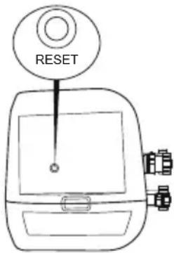
HEATING RESET
When using the Lay-Z-Spa for first time, or after a long period of inactivity, be sure to press the reset button on the pump using a small and thin object.
If the temperature on the control panel (or the water temperature) has not changed 4-5 hours after activation of the heating system, use a thin object to press the RESET BUTTON, and restart the heating system.
text_image
RESETIMPORTANT: The heating system will not operate if the outside temperature is above 40^ C (104 °F) or if the Lay-Z-Spa is under direct sunlight. Under these conditions, please wait until a cooler time of day before pressing the RESET BUTTON with a thin object and restarting the heating system.
IMPORTANT
To reach 40^ C ( 104^ F), the heating duration required is based on the starting water temperature and ambient temperature, the data below is purely for reference. To display the current water temperature, run the filter system for at least a minute.
| Ambient Temperature | Water Temperature | Set Temperature | Heating Duration |
| 10°C(50°F) | 10°C(50°F) | 40°C(104°F) | 18.5h - 21.5h |
| 15°C(59°F) | 15°C(59°F) | 40°C(104°F) | 15h - 18h |
| 20°C(68°F) | 20°C(68°F) | 40°C(104°F) | 11.5h - 14.5h |
| 25°C(77°F) | 25°C(77°F) | 40°C(104°F) | 8.5h - 11h |
| 30°C(86°F) | 30°C(86°F) | 40°C(104°F) | 5.5h - 7.5h |
- Be sure to cover the spa with the spa cover whenever the heating function is activated. Leaving the spa uncovered will increase the heating duration required.
- When the spa is assembled with water, do not switch off the spa heater if the temperature is lower than 6^(42.8^) .
text_image
Diagram showing a device emitting heat from a device with a magnified view of its internal components.| Power Rate Massage Tube PowerHeat Element Power Pump Power | ||||
| 220-240V AC,50Hz, Single Phase2,050W at 20°C | 2,000W at 20°C | 50W 1200W | 800W | |
MAINTENANCE
CAUTION: You must ensure the pump is unplugged before beginning spa maintenance to avoid risk of injury or death.
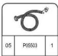
Adding Air: Your spa will require additional air to be added from time to time.
Changes in temperature from day to night will change the pressure in the spa and may cause a certain amount of deflation. Please follow the assembly instructions and inflate to the accurate pressure needed.
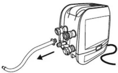
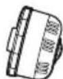
When you need to use the pump for inflation, please block the hoses to prevent water from escaping, then disconnect the pump, screw on the cap to avoid water coming out from the air pipe.
text_image
coming out from the air pipe.Cover Maintenance
The cover shall be cleaned inside and out periodically using a suitable solution that includes adequate disinfection (e.g. 10 mg/l of Free Chlorine).
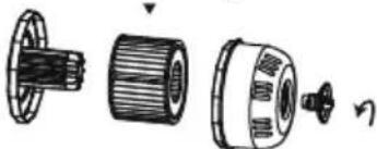
Filter Cartridge Maintenance
To ensure your spa water stays clean, check and clean your filter cartridges every day follow the steps below.
NOTE: We recommend changing your filter cartridges every week or, if the filter cartridges remain soiled and discolored, they should be replaced.
Filter Set
Filter Cartridge
natural_image
Exploded view diagram of a mechanical assembly showing internal components (no text or labels)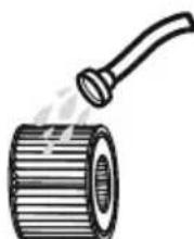
natural_image
Illustration of a pipe roller with a handle emitting steam (no text or symbols)Water Maintenance
Many pollutants in the water settle on surfaces below the water line. These pollutants can cause bacterial, algal or fungal growth. It is recommended that spas are cleaned as regularly as necessary. After a time, tenacious stains or biofilms may develop on the accessible surfaces below the water line or high concentrations of salts or unwanted reaction by-products may also occur. Depending on hygienic condition, cleanliness, visibility, odour, debris and stains, it is recommended to change the water completely and clean/disinfect the spa. When emptying the spa, the regulations and the instructions for draining the water shall be observed. Keeping your spa water clean and chemically balanced is necessary. Simply cleaning the filter cartridge is not enough for proper maintenance, we recommend you use pool chemicals to maintain water chemistry and chlorine or bromine tablets (do not use granules) with the chemical dispenser.
Water quality will be directly related to frequency of use, number of users and overall maintenance of the spa. The water should be changed every 3 days if there is no chemical treatment being performed with the water.
It is highly recommended to use tap water for spa filling to minimize the influence of unwanted content, such as minerals. Barefoot areas and relaxing areas shall be cleaned as well. No cleaning water may flow into the spa or spa water cycle. The dirt and cleaning agents shall be rinsed carefully to drain in the spa surround.
Note: We recommend you take a shower before using your Lay-Z-Spa, as cosmetic products, lotions, and other residues on the skin can quickly degrade water quality. To use the chemical dispenser, please follow the below instruction.
Using chemical tablets (not included):
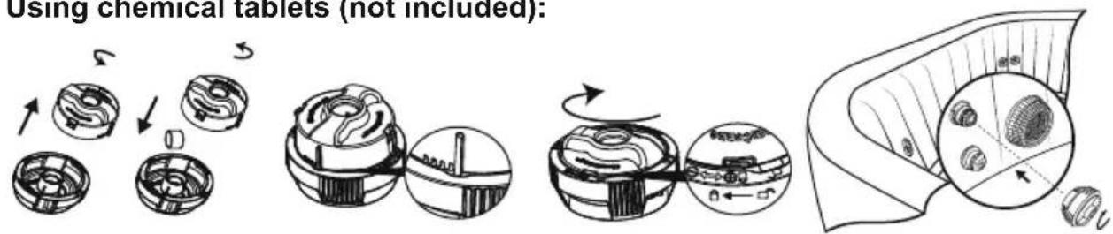
text_image
Using chemical tablets (not included):Using chemical liquid (not included):
natural_image
Illustration of a hot water bath connected to a circular fan with a pointer (no text or symbols)NOTE: Remove the chemical dispenser from spa when the spa is in use.
IMPORTANT: After performing chemical maintenance and before using the spa, use a test kit (not included) to test the water chemistry. We recommend maintaining your water as below table.
| pH | Total Alkalinity | Free Chlorine |
| 7.4-7.6 | 80-120ppm | 2-4ppm |
NOTE: Damage resulting from chemical imbalance is not covered by the warranty. Pool chemicals are potentially toxic and should be handled with care. There are serious health risks from chemical vapors and the incorrect labeling and storage of chemical containers. Please consult your local pool supply retailer for more information about chemical maintenance. Pay close attention to the chemical manufacturer's instructions. Spa damage resulting from misuse of chemicals and mismanagement of spa water is not covered by the warranty.
DISASSEMBLY AND STORAGE
DRAINING THE SPA
1.2.
natural_image
Diagram of a device with a close-up view showing internal components (no text or symbols)
text_image
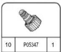
P053473.4.

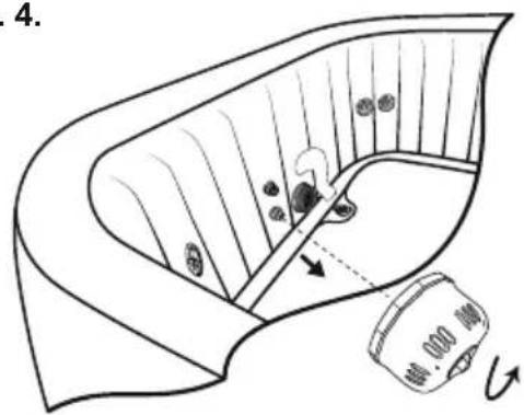
text_image
4.
natural_image
Diagram of a biological structure with arrows indicating internal components and a magnified inset showing cellular structures (no text or labels)5.6.

natural_image
Line drawing of a portable device with a hand panel and a separate device, both shown in line with an arrow indicating direction (no text or symbols present)
text_image
Diagram illustrating a mechanical assembly process with labeled parts and a magnified view showing the assembly being cut by 8 units.
natural_image
Line drawing of a portable electronic device with connectors and a cable (no text or symbols)Make sure the spa and pump are completely dry. This is essential to extend the life of the spa. We recommend using the pump to blow dry the spa, pump and pipes. Remove the filter sets and discard the used filter cartridges. Re-attach the two stopper caps onto the spa's inlet and outlet valves. It is recommended you store the spa in its original package in a warm [above 15°C (59°F)] and dry place.
CLEANING THE SPA
Detergent residues and dissolved solids from bathing suits and chemicals may build up on the spa walls. Use soap and water to clean the walls and rinse thoroughly. NOTE: DO NOT use hard brushes or abrasive cleaners.
DEFLATION
Your spa is equipped with a deflation function to remove all the air from inside the chamber to make it easier to pack and store.
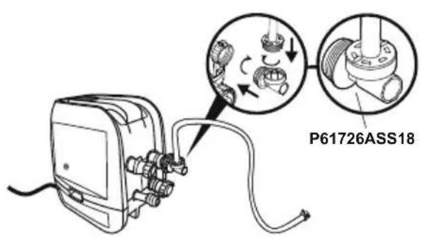
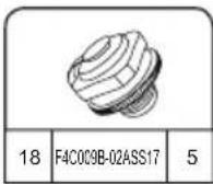
text_image
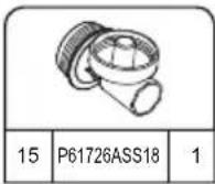
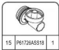
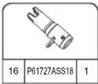
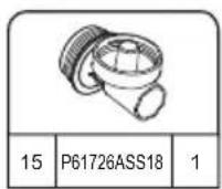
P61726ASS18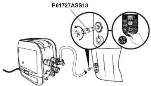
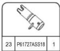
text_image
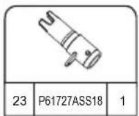
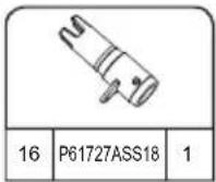
P61727ASS18REPAIR
For PVC part.
If the spa is torn or punctured, use the provided underwater adhesive repair patch.
- Clean area to be repaired.
- Carefully peel patch
- Press patch over area to be repaired.
- Wait 30 seconds before inflation.
For Tritech PVC material.
If the spa is torn or punctured, use the provided PVC repair patch and glue (not included) following these steps:
- Clean and dry area to be repaired.
- Cut the provided PVC patch to appropriate size.
- Use glue (not included) to coat the one side of the newly cut patch. Make sure the glue is evenly distributed.
- Wait for 30 seconds and then place the cut patch with glue over the damaged area.
- Smooth out any bubbles of air that may be trapped underneath, and press firmly for two minutes.
- The product is once again ready for use. Repeat this process should further leaks occur.
- Wait 30 minutes before inflation.
Disposal

Waste electrical products should not be disposed of with household waste. Please recycle where facilities exist. Check with your local authority or retailer for recycling advice.
TROUBLESHOOTING
Bestway strives to provide the most trouble-free spas on the market.
If you experience any problems whatsoever, do not hesitate to contact Bestway or your authorized dealer. Here are some helpful tips to help you to diagnose and rectify some common sources of trouble.
Problems Probable Causes Solutions
| Pump does not operate - Power failure- Power circuits broken | - Check power source- For assistance, please visit the support section on our website, www.bestwaycorp.com | |
| Pump does not heat properly - Temperature set too low- Dirty Filter Cartridge- The thermal cut-out cut off- Spa is not covered- Heating element failed or fuse cutout | - Set to a higher temperature refer to section pump operation- Clean/replace the filter cartridge refer to section filter cartridge cleaning and replacement- Unplug the pump, and put the plug in a dry, cool place. Only restart the pump when the water temperature reaches 35°C (95°F) or lower- Attach the cover- For assistance, please visit the support section on our website, www.bestwaycorp.com | |
| Lay-Z-Massage System does not work | - Air Pump is overheating- The Lay-Z-Spa Massage stops automatically- Air pump is broken | - Unplug the pump and wait two hours until the pump has cooled. Insert the plug and press the Lay-Z-Massage System Button- Press the Lay-Z-Massage System Button to reactivate- For assistance, please visit the support section on our website, www.bestwaycorp.com |
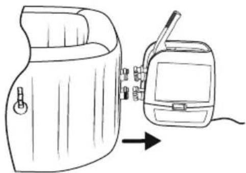
| Pump adapters are not level with the spa adapters | One characteristic of PVC is that it changes shape, which is normal | - Elevate the pump with wood or another type of insulated material to bring the pump's adapters level with the spa's adapters |
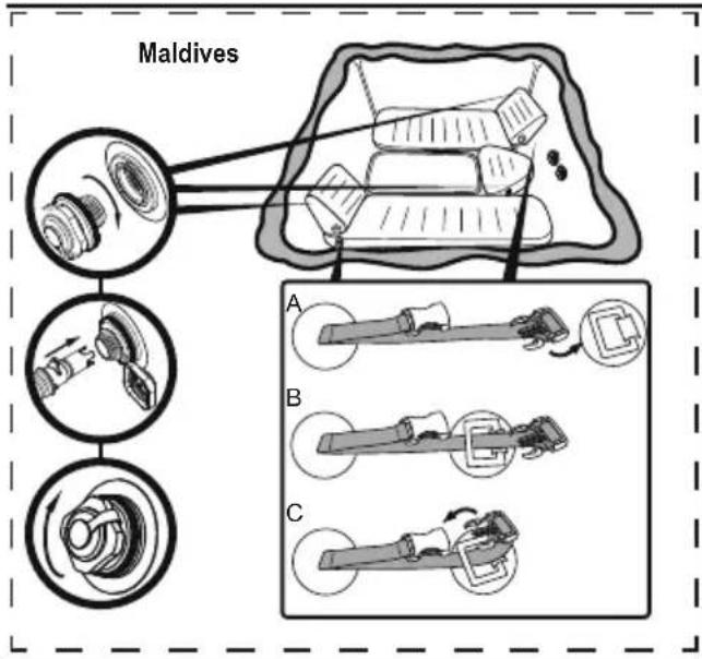
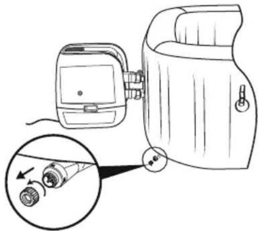
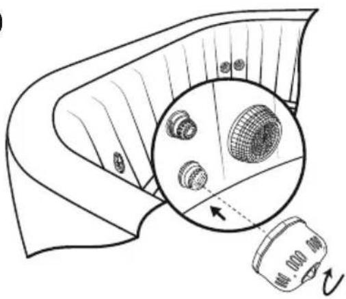
| Spa pool leakage - Spa is torn or punctured- Air valve is loose | - Use provided repair patch- Using soapy water, cover the air-valve to check if air is leaking, if so, use the provided wrench to fasten the air-valve following these steps:1. Deflate the spa.2. With one hand, hold the backside of the air valve from the inner side of the spa wall and turn the wrench clockwise. | |
| Water is not clean - Insufficient filtering time- Dirty Filter Cartridge- Improper water maintenance | - Increase filtration time- Clean/replace the Filter Cartridge (refer to Filter Cartridge Cleaning and Replacement section)- Refer to the chemical manufacturer's instructions | |
| PRCD test failed Something wrong with the spa - For assistance, please visit the support section on our website, www.bestwaycorp.com | ||
| Control panel is not working | The control panel has an auto-lock, which is activated after 5 minutes of inactivity. The LED display has one icon:If the lock icon is highlighted, the control panel is locked.- Control panel is not activated. | - To unlock the control panel, press thebutton for 3 seconds.If the control panel will not unlock, restart the pump – unplug and plug in the pump- Press the on/off button for 2 seconds. If the problem persists,- For assistance, please visit the support section on our website, www.bestwaycorp.com |
| What kind of chemicals should be used for water maintenance? | Please consult your local chemical supplier for information about chemical maintenance.Pay close attention to the chemical manufacturer's instructions | |
| Water leaks from the adapters between the pump and spa | - Seals are missing inside the pump adapters- Seals are not in the correct position- Seals are damaged- Adapters are not tightened correctly | - Insert the stopper caps on the spa ports to prevent the water from escaping and disconnect the pump. Check if the seals are in place.- If the seals are not in the correct position, open the gears, and place the seals in correct position.- If the seals are damaged, they must be replaced. For assistance, please visit the support section on our website, www.bestwaycorp.com.- If the seals are in correct position, the adapters are not tightened correctly. Connect the pump to the spa, hand-tighten the adapters, and remove the stopper caps from the spa ports. If there is leakage, tighten the adapter until there is no leakage. |
| The HydroJetTM system button is not working | - The button is on but water does not come out of the spa- The HydroJet system shuts off automatically after 1 hour- There is some air trapped in the hoses | - The thermofuse cut off the power due to a high temperature being reached by the motor. Power off the spa heater for about 3 hours, wait for the temperature to drop, and restart the HydroJet function. If the problem remains, please visit the support section on our website, www.bestwaycorp.com.- Restart the HydroJet function again to enjoy your spa- Disconnect the water pump and reconnect after draining some water |
CAUSES REASONS SOLUTIONS
The water flow sensors work without pressing the filter or heat button. | 1. The water flow sensor flags didn't fall back into the correct position.2. The water flow sensors are broken. | 1. Unplug the plug gently, strike the side of the pump but not violently, and plug it back in.2. For assistance, please visit the support section on our website, www.bestwaycorp.com. |
After starting or during the functions of filtering or/and heating, the water flow sensors do not detect water flow. | 1. You forgot to remove the 2 stopper caps from inside the pool.2. Filter cartridges are dirty.3. Activate the filter or heat system and put your hand in front of the outlet pipe inside the pool to check if you can feel water flowing out.a. If no water flows out the water pump is broken.b. Water flows out but the alarmEP appears, the water flow sensors are broken.4. Filter blockage5. Bent pipes or poor water flow through the plastic pipes of the liner6. Debris screens are blocked: debris screens can become blocked by hard water due to calcium build-up.7. Perished washersThe washers within the spa couplings may have become perished or worn. | 1. Remove the 2 stopper caps before heating, refer to Assembly section in the User's Manual.2. Remove the filter set from inside the pool and push the filter or heat button. If no alarm appears, clean or change the filter cartridges install the filter set inside the pool.3. For assistance, please visit the support section on our website, www.bestwaycorp.com.4. Clean the filter and check for damage. Replace or re-install as necessary. For assistance, please visit the support section on our website, www.bestwaycorp.com.5. Please check through the spa connection to see if the pipes are bending. For assistance, please visit the support section on our website, www.bestwaycorp.com.6. Empty the spa and place a garden hose inside the pipes to wash the debris. To be sure all debris are removed, perform the operation from the outside and inside of the spa.Use a toothbrush to remove any stubborn debris.For assistance, please visit the support section on our website, www.bestwaycorp.com.7. Check the washers inside the coupling for damage. Unscrew the couplings and remove the washer for further inspection.For assistance, please visit the support section on our website, www.bestwaycorp.com. |
The pump's thermometer reads the water temperature below 4°C (40°F). | 1. The water temperature is lower than 4°C (40°F)2. If the water temperature is higher than 7°C (44.6°F), the pump's thermometer is broken. | 1. The spa is not designed to operate with water temperatures lower than 4°C (40°F). Unplug the pump and only re-start the pump when the water temperature reaches 6°C (43°F).2. For assistance, please visit the support section on our website, www.bestwaycorp.com. |
The pump's thermometer reads the water temperature over 50°C (122°F). | 1. The water temperature is over 50°C (122°F)2. If the water temperature is lower than 45°C (113°F), the pump's thermometer is broken. | 1. The spa is not designed to operate with water temperatures greater than 40°C (104°F). Unplug the pump and only re-start the pump when the water temperature reaches 38°C (100°F) or lower.IMPORTANT: Before you re-start the pump, push the pump's reset button.2. For assistance, please visit the support section on our website, www.bestwaycorp.com. |
The pump's thermometer connections have issues. | 1. The pump's thermometer connectors don't work properly.2. The pump's thermometer is broken. | For assistance, please visit the support section on our website, www.bestwaycorp.com. |
The thermal cut-out cut off. | The manual reset thermal cut-out trips off. 1. Unplug the pump and push the reset button, then plug the pump back in.2. In case the alarm still remains, check the RESET BUTTON section in manual.3. For assistance, please visit the support section on our website, www.bestwaycorp.com. | |
Water leakage inside the pump. The  | system has detected some water leakage inside the pump. | For assistance, please visit the support section on our website, www.bestwaycorp.com. |
Ground Connection Failed. 1. The  | ground bonding of your home has some problem.2. The pump has some problem. | For assistance, please visit the support section on our website, www.bestwaycorp.com. |
natural_image
Abstract geometric diagram with overlapping planes and shaded regions (no text or symbols)MALDIVES HYDROJET PRO S200102 (60033)
— 2.01 m x 2.01 m x 80 cm / 79" x 79" x 31.5"

5 - 7 1-1.5°C/h

2-3°F/h

1,325 L/h
350 gal/h

1.2PSI 0.08Bar

1050 L
277 gal

1118 kg
2,465 Lb


HAWAII HYDROJET PRO S200102 (60031)
.— 1.80 m x 1.80 m x 71 cm / 71" x 71" x 28"

4 - 6 1.5-2°C/h

3-4°F/h

1,325 L/h
350 gal/h

1.2PSI 0.08Bar

795 L
210 gal

848 kg 1,869 Lb


INSTALAÇÃO
natural_image
Simple line drawing of a folded fabric or material (no text or symbols)
natural_image
Diagram of a cable being inserted into an electrical device (no text or symbols present)
natural_image
Line drawing of an electrical plug device connected to a circular icon showing a plug with lightning and up arrows (no text or symbols)4

flowchart
graph TD
    A["Device Inserted"] --> B["Measurement Equipment"]
    B --> C["Control Panel Display"]
    C --> D["Digital Display Control"]
    D --> E["Time Measurement"]
    E --> F["5 min. Time"]

5 min.

text_image
Maldives A B C5.25.1

natural_image
Diagram showing two rectangular blocks with a curved arrow pointing downward from one to the other (no text or symbols)6

text_image
Diagram illustrating a medical procedure for using a pressure monitor, showing step-by-step instructions and validation outcomes.7

natural_image
Line drawing of a handheld electronic device with hoses and connectors, no text or symbols present8

natural_image
Line drawing of a portable device with a hand panel and a walkie-talkie, showing no text or symbols.9

natural_image
Diagram of a mechanical component with internal gears and a magnified inset showing internal structure (no text or labels)10

natural_image
Diagram showing a device emitting a surface with a magnified inset of a grid-patterned object (no text or symbols)11

text_image
MAX. MIN.16
TESTE DO PRCD

text_image
1 2 3 4
text_image
8.8.6 °C °F 6/8 Δ e/Ftext_image
Technical diagram showing a device connected to a device with an inset close-up of internal components and a final output arrow.natural_image
Line drawing of a portable electronic device with cables and connectors, no text or symbols presentUTILIZAÇÃO DO SPA

natural_image
Technical line drawing of a mechanical device with no visible text or symbols
natural_image
Technical line drawing of a mechanical device with no visible text or symbols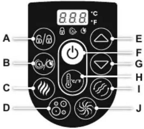
text_image
A B C D 8.8.8 °C °F E F G H I Jtext_image
Diagram illustrating hand positioning and movement of a flower, showing positive and negative directional changes with arrows.
text_image
Diagram showing a device emitting heat from a box, with an inset magnified view of devices emitting heat.natural_image
Line drawing of a hot pot with a device and a circular fan-like object nearby (no text or symbols)natural_image
Diagram of a device with a close-up view showing internal components (no text or symbols)
text_image
P053473.4.

text_image
4.
natural_image
Diagram of a biological structure with arrows indicating internal components and a magnified inset showing circular elements (no text or labels)5.6.

natural_image
Line drawing of a portable device with a hand panel and a separate device, both connected by an arrow (no text or symbols present)
text_image
Diagram illustrating a mechanical assembly process with labeled parts and a magnified view showing a component being processed.
natural_image
Line drawing of a portable electronic device with connectors and a cable (no text or symbols)natural_image
Abstract geometric diagram with overlapping planes and shaded regions (no text or symbols)MALDIVES HYDROJET PRO S200102 (60033)
— 2.01 m x 2.01 m x 80 cm / 79" x 79" x 31.5"

5 - 7 1-1.5°C/h

2-3°F/h

1,325 L/h
350 gal/h

1.2PSI 0.08Bar

1050 L
277 gal

1118 kg
2,465 Lb


HAWAII HYDROJET PRO S200102 (60031)
.— 1.80 m x 1.80 m x 71 cm / 71" x 71" x 28"

4 - 6 1.5-2°C/h

3-4°F/h

1,325 L/h
350 gal/h

1.2PSI 0.08Bar

795 L
210 gal

848 kg 1,869 Lb


INSTALACIÓN

INSTRUCCIONES
PARA USO EN
INVIERNO

text_image
< 10°C(50°F)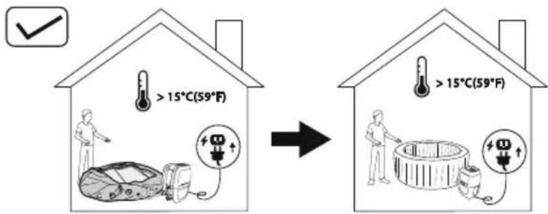
text_image
>15°C(59°F) >15°C(59°F)natural_image
Simple line drawing of a folded fabric or material (no text or symbols)
natural_image
Diagram of a cable being inserted into an electronic device (no text or symbols present)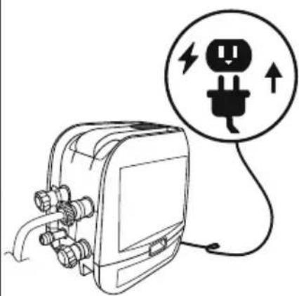
natural_image
Line drawing of an electrical plug connected to a device with a circular warning symbol (no text or labels)4

flowchart
graph TD
    A["5 min. Pump"] --> B["100% pump assembly"]
    B --> C["25% device with power switch"]
    C --> D["30% device with control panel"]
    D --> E["40% device with digital display"]

5 min.

text_image
Maldives A B C5.25.1

natural_image
Diagram showing two rectangular blocks with a curved arrow pointing downward from one to the other (no text or symbols)6

text_image
Diagram illustrating a medical procedure for using a pressure monitor, showing step-by-step instructions and validation outcomes.7

natural_image
Line drawing of a handheld electronic device with hoses and connectors, no text or symbols present8

natural_image
Line drawing of a portable device with a hand panel and a walkie-talkie, showing no text or symbols.9

natural_image
Diagram of a mechanical component with internal gears and a magnified inset showing internal structure (no text or labels)10

natural_image
Diagram of a mechanical component with a magnified inset showing internal components (no text or symbols)11

text_image
MAX. MIN.16
PRUEBA DE PRCD
text_image
1 2 3 4text_image
Technical diagram showing a device connected to a device with an inset close-up of internal components and a final output arrow.natural_image
Line drawing of a portable electronic device with cable and connectors, no text or symbols presentUSO DEL SPA

natural_image
Technical line drawing of a mechanical device with no visible text or symbols
natural_image
Technical line drawing of a mechanical device with no visible text or symbols
text_image
A B C D 8.8.8 °C °F E F G H I Jtext_image
Diagram illustrating hand positioning and movement of a flower, showing positive and negative directional changes with arrows.
text_image
Diagram showing a device emitting heat from a device with labeled components and a smoke iconnatural_image
Line drawing of a hot pot with a device and a circular fan-like object nearby (no text or symbols)natural_image
Diagram of a device with a close-up inset showing internal components (no text or symbols)
text_image
P053473.4.

text_image
4.
natural_image
Diagram of a biological structure with arrows indicating internal components and a magnified inset showing circular elements (no text or labels)5.6.

natural_image
Line drawing of a portable device with a hand panel and a separate device with a cable, both shown without any text or symbols.
text_image
Diagram illustrating a mechanical assembly process with labeled parts and a magnified view showing a component being processed.
natural_image
Line drawing of a portable electronic device with connectors and a cable (no text or symbols)natural_image
Abstract geometric diagram with overlapping planes and shaded regions (no text or symbols)MALDIVES HYDROJET PRO S200102 (60033)
— 2.01 m x 2.01 m x 80 cm / 79" x 79" x 31.5"

5 - 7 1-1.5°C/h

2-3°F/h

1,325 L/h
350 gal/h

1.2PSI 0.08Bar

1050 L
277 gal

1118 kg
2,465 Lb


HAWAII HYDROJET PRO S200102 (60031)
.— 1.80 m x 1.80 m x 71 cm / 71" x 71" x 28"

4 - 6 1.5-2°C/h

3-4°F/h

1,325 L/h
350 gal/h

1.2PSI 0.08Bar

795 L
210 gal

848 kg 1,869 Lb


AUFBAU
natural_image
Simple line drawing of a folded fabric or material (no text or symbols)
natural_image
Diagram of a medical device with tubing and connectors, showing no text or symbols
natural_image
Line drawing of an electrical plug connected to a device with a circular warning symbol (no text or labels)4

flowchart
graph TD
    A["Device Inserted"] --> B["Measurement Equipment"]
    B --> C["Control Panel Display"]
    C --> D["Digital Display Control"]
    D --> E["Time Measurement"]
    E --> F["5 min. Time"]

5 min.

text_image
Maldives A B C5.25.1

natural_image
Diagram showing two rectangular blocks with a curved arrow pointing downward from one to the other (no text or symbols)6
text_image
Diagram illustrating a medical procedure for using a pressure monitor, showing step-by-step instructions and validation outcomes.7

natural_image
Line drawing of a handheld electronic device with hoses and connectors, no text or symbols present8

natural_image
Line drawing of a portable device with a hand panel and a walkie-talkie, showing no text or symbols.9

natural_image
Diagram of a mechanical component with internal gears and a magnified inset showing internal structure (no text or labels)10

natural_image
Diagram of a mechanical component with a magnified inset showing internal components (no text or symbols)11

text_image
MAX. MIN.16
PRCD-Test


text_image
Technical diagram showing a device's internal components and a close-up of a component with a magnified view.natural_image
Line drawing of a portable electronic device with cables and connectors, no text or symbols presentnatural_image
Technical line drawing of a mechanical device with no visible text or symbols
natural_image
Technical line drawing of a mechanical device with no visible text or symbols
text_image
A B C D 8.8.8 °C °F E F G H I Jtext_image
Diagram illustrating hand manipulation of a flower with directional arrows and polarity signs
text_image
Diagram showing a device emitting heat from a device with labeled components and a smoke icontext_image
Diagram illustrating a mechanical assembly process with labeled steps and a magnified inset showing internal components.natural_image
Line drawing of a hot pot with a device and a circular fan-like object (no text or symbols)ENTLEEREN DES WHIRLPOOLS
1.2.

natural_image
Line drawing of a device with a close-up inset showing a connector detail (no text or symbols)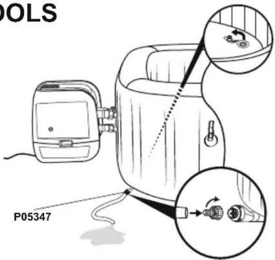
text_image
POLS P053473.4.

text_image
4.
natural_image
Diagram of a biological structure with arrows indicating internal components and a magnified inset showing circular elements (no text or labels)5.6.

natural_image
Line drawing of a portable device with a hand panel and a separate device, both connected by an arrow (no text or symbols present)
text_image
Diagram illustrating a mechanical assembly process with labeled parts and a magnified view showing a component being processed.
natural_image
Line drawing of a portable electronic device with connectors and a cable (no text or symbols)natural_image
Abstract geometric diagram with overlapping planes and shaded regions (no text or symbols)MALDIVES HYDROJET PRO S200102 (60033)
— 2.01 m x 2.01 m x 80 cm / 79" x 79" x 31.5"

5 - 7 1-1.5°C/h

2-3°F/h

1,325 L/h
350 gal/h

1.2PSI 0.08Bar

1050 L
277 gal

1118 kg
2,465 Lb


HAWAII HYDROJET PRO S200102 (60031)
.— 1.80 m x 1.80 m x 71 cm / 71" x 71" x 28"

4 - 6 1.5-2°C/h

3-4°F/h

1,325 L/h
350 gal/h

1.2PSI 0.08Bar

795 L
210 gal

848 kg 1,869 Lb


ASENNUS

ASENNUSOHJEET
TALVELLA
text_image
< 10°C(50°F)
text_image
> 15°C(59°F) > 15°C(59°F)natural_image
Simple line drawing of a folded fabric or material (no text or symbols)
natural_image
Diagram of a cable being inserted into an electrical device (no text or symbols present)
natural_image
Line drawing of an electrical plug connected to a device with a circular warning symbol (no text or labels)4

flowchart
graph TD
    A["5 min. Pump"] --> B["100% pump assembly"]
    B --> C["25% device with power switch"]
    C --> D["30% device with control panel"]
    D --> E["40% device with digital display"]

5 min.

text_image
Maldives A B C5.25.1

natural_image
Diagram showing two rectangular blocks with a curved arrow pointing downward from one to the other (no text or symbols)6

text_image
Diagram illustrating a medical procedure for using a pressure monitor, showing step-by-step instructions and confirmation signs.7

natural_image
Line drawing of a handheld electronic device with hoses and connectors, no text or symbols present8

natural_image
Line drawing of a portable device with a hand panel and a walkie-talkie, showing no text or symbols.9

natural_image
Diagram of a mechanical component with internal gears and a magnified inset showing internal structure (no text or labels)10

natural_image
Diagram showing a device emitting a surface with a magnified inset of a grid-patterned object (no text or symbols)11

text_image
MAX. MIN.16
PRCS Tset


text_image
Technical diagram showing a device with internal components and a close-up of a component with a magnified view.natural_image
Line drawing of a portable electronic device with cable and connectors, no text or symbols presentSPA-ALTAAN KÄYTTÄMINEN

natural_image
Technical line drawing of a mechanical device with no visible text or symbols
natural_image
Technical line drawing of a mechanical device with no visible text or symbols
text_image
A B C D 8.8.8 °C °F E F G H I Jtext_image
Diagram illustrating hand manipulation of a flower with directional arrows and polarity signs
text_image
Diagram showing a device emitting heat from a device with a magnified view of its internal components.natural_image
Line drawings of a bathtub, interior compartments, and medical equipment with no visible text or symbolsKannen huolto
text_image
Diagram illustrating a mechanical assembly process with labeled steps and a magnified inset showing internal components.natural_image
Simple line drawing of a hot water bath connected to a device with a circular fan-like pattern (no text or symbols)natural_image
Diagram of a device with a close-up inset showing internal components (no text or symbols)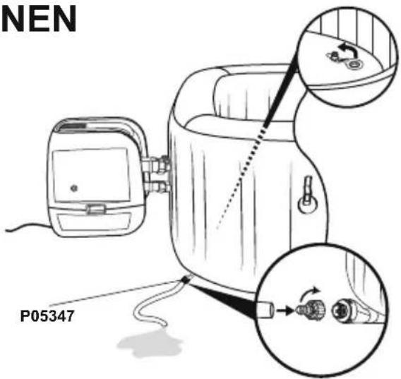
text_image
NEN P053473.4.
text_image
4.
natural_image
Diagram of a biological structure with arrows indicating internal components and a magnified inset showing circular elements (no text or labels)5.6.

natural_image
Line drawing of a portable device with a hand panel and a separate device with a cable, both connected by an arrow (no text or symbols present)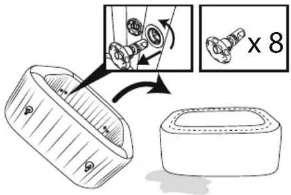
text_image
Diagram illustrating a mechanical assembly process with labeled parts and a magnified view showing a component being processed.
natural_image
Line drawing of a portable electronic device with connectors and a cable (no text or symbols)natural_image
Abstract geometric diagram with overlapping planes and shaded regions (no text or symbols)MALDIVES HYDROJET PRO S200102 (60033)
— 2.01 m x 2.01 m x 80 cm / 79" x 79" x 31.5"

5 - 7 1-1.5°C/h

2-3°F/h

1,325 L/h
350 gal/h

1.2PSI 0.08Bar
1050 L
277 gal

1118 kg
2,465 Lb


HAWAII HYDROJET PRO S200102 (60031)
— 1.80 m x 1.80 m x 71 cm / 71" x 71" x 28"

4 - 6 1.5-2°C/h

3-4°F/h

1,325 L/h
350 gal/h

1.2PSI 0.08Bar

795 L
210 gal

848 kg 1,869 Lb


INSTALLATIE

INSTALLATIE-INSTRUCTIES
IN DE WINTER

text_image
< 10°C(50°F)
text_image
> 15°C(59°F) > 15°C(59°F)natural_image
Simple line drawing of a folded fabric or material (no text or symbols)
natural_image
Diagram of a medical device with tubing and connectors, showing no text or symbols
natural_image
Line drawing of an electrical plug connected to a device with a warning symbol (no text or labels)4

flowchart
graph TD
    A["5 min. Pump"] --> B["100% pump assembly"]
    B --> C["25% device with power switch"]
    C --> D["30% device with control panel"]
    D --> E["40% device with digital display"]

5 min.

text_image
Maldives A B C5.25.1

natural_image
Diagram showing two rectangular blocks with a curved arrow pointing downward from one to the other (no text or symbols)6

text_image
Diagram illustrating a medical procedure for using a pressure monitor, showing step-by-step instructions and validation outcomes.7

natural_image
Line drawing of a handheld electronic device with hoses and connectors, no text or symbols present8

natural_image
Line drawing of a portable device with a hand panel and a walkie-talkie, showing no text or symbols.9

natural_image
Diagram of a mechanical component with internal gears and a magnified inset showing internal structure (no text or labels)10

natural_image
Diagram showing a device emitting a surface with a magnified inset of a grid-patterned object (no text or symbols)11

text_image
MAX. MIN.16
text_image
Technical diagram showing a device's internal components and a process flow with labeled parts and directional arrows.natural_image
Line drawing of a medical device with tubing and connectors, no text or symbols presentnatural_image
Technical line drawing of a mechanical device with no visible text or symbols
natural_image
Technical line drawing of a mechanical device with no visible text or symbols
text_image
A B C D 8.8.8 °C °F E F G H I Jtext_image
Diagram illustrating hand manipulation of a flower with directional arrows and polarity signs
text_image
Diagram showing a device emitting heat from a device, with a magnified inset highlighting internal components.natural_image
Exploded view diagram of a mechanical component showing internal parts and assembly (no text or labels)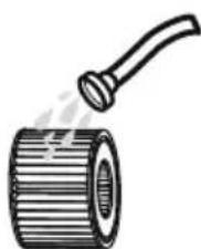
natural_image
Illustration of a cylindrical pipe with a handle emitting vapor (no text or symbols)Wateronderhoud
text_image
Diagram illustrating a mechanical assembly process with labeled parts and directional arrows, including a magnified inset showing internal components.natural_image
Simple line drawing of a hot water bath connected to a device with a circular inset showing a fan-like pattern (no text or symbols)natural_image
Line drawing of a device with a close-up inset showing a connector detail (no text or symbols)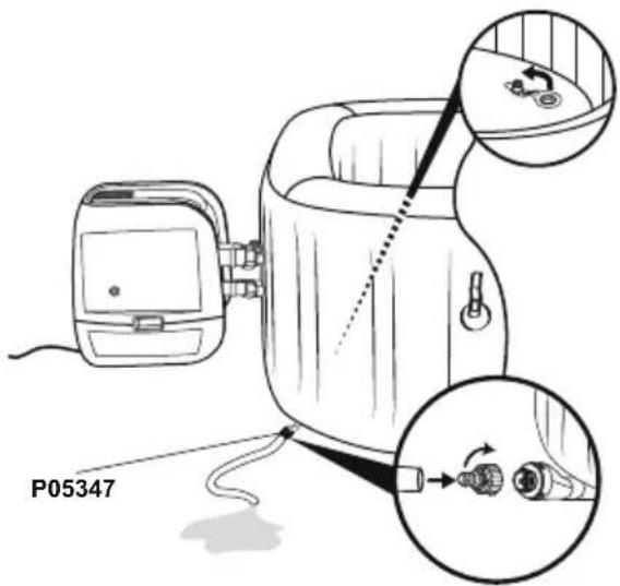
text_image
P053473.4.

text_image
4.
natural_image
Diagram of a biological structure with arrows indicating internal components and a magnified inset showing cellular or vesicular details (no text or labels)5.6.

natural_image
Line drawing of a portable device next to a handheld device with a scroll, showing no text or symbols.
text_image
Diagram illustrating a mechanical assembly process with labeled parts and magnified detail view
natural_image
Line drawing of a portable electronic device with connectors and a cable (no text or symbols)natural_image
Abstract geometric diagram composed of overlapping planes and polygons (no text or symbols)MALDIVES HYDROJET PRO S200102 (60033)
— 2.01 m x 2.01 m x 80 cm / 79" x 79" x 31.5"

5 - 7 1-1.5°C/h

2-3°F/h

1,325 L/h
350 gal/h

1.2PSI 0.08Bar

1050 L
277 gal

1118 kg
2,465 Lb


HAWAII HYDROJET PRO S200102 (60031)
— 1.80 m x 1.80 m x 71 cm / 71" x 71" x 28"

4 - 6 1.5-2°C/h

3-4°F/h

1,325 L/h
350 gal/h

1.2PSI 0.08Bar

795 L
210 gal

848 kg 1,869 Lb


INSTALLAZIONE
natural_image
Simple line drawing of a folded fabric or cushion (no text or symbols)
natural_image
Diagram of a cable being inserted into an electronic device (no text or symbols present)
natural_image
Line drawing of an electrical plug connected to a device with a circular warning symbol (no text or labels)4

flowchart
graph TD
    A["5 min. Pump"] --> B["Switch: 2.5"]
    B --> C["Power Button: 5.25"]
    C --> D["Digital Display: 2.89"]
    D --> E["Time Measurement: 5 min."]

5 min.

text_image
Maldives A B C5.25.1

natural_image
Diagram showing two rectangular blocks with a curved arrow pointing downward from one to the other (no text or symbols)6

text_image
Diagram illustrating a medical procedure for using a pressure monitor, showing step-by-step instructions and validation outcomes.7

natural_image
Line drawing of a handheld electronic device with hoses and connectors, no text or symbols present8

natural_image
Line drawing of a portable device with a hand panel and a walkie-talkie, showing no text or symbols.9

natural_image
Diagram of a mechanical component with internal gears and a magnified inset showing internal structure (no text or labels)10
natural_image
Diagram of a mechanical component with a magnified inset showing internal components (no text or symbols)11

text_image
MAX. MIN.16
text_image
8.86 °C 6/10s +/-text_image
Technical diagram showing a device with internal components and a close-up of a component with a magnified view.natural_image
Line drawing of an electronic device with wires and connectors, no text or symbols presentUTILIZZO DELLA SPA

natural_image
Technical line drawing of a mechanical device with no visible text or symbols
natural_image
Technical line drawing of a mechanical device with no visible text or symbols
text_image
A B C D 8.8.8 °C °F E F G H I Jtext_image
Diagram illustrating hand positioning and movement of a flower, showing positive and negative directional changes with arrows.
text_image
Diagram showing a device emitting heat from a box, with an inset image of a device emitting heat.natural_image
Illustration of a hot water bath connected to a device with a circular fan-like pattern (no text or symbols)natural_image
Diagram of a device with a close-up view showing internal components (no text or symbols)
text_image
CINA P053473.4.

text_image
4.
natural_image
Diagram of a biological structure with arrows indicating internal components and a magnified inset showing circular elements (no text or labels)5.6.
natural_image
Line drawing of a device with a device connected to a battery pack, showing internal components and an arrow indicating direction (no text or symbols)
text_image
Diagram illustrating a mechanical assembly process with labeled parts and a magnified view showing a component being processed.
natural_image
Line drawing of a portable electronic device with connectors and a cable (no text or symbols)natural_image
Abstract geometric diagram with overlapping planes and shaded regions (no text or symbols)MALDIVES HYDROJET PRO S200102 (60033)
— 2.01 m x 2.01 m x 80 cm / 79" x 79" x 31.5"

5 - 7 1-1.5°C/h

2-3°F/h

1,325 L/h
350 gal/h

1.2PSI 0.08Bar

1050 L
277 gal

1118 kg
2,465 Lb


HAWAII HYDROJET PRO S200102 (60031)
— 1.80 m x 1.80 m x 71 cm / 71" x 71" x 28"

4 - 6 1.5-2°C/h

3-4°F/h

1,325 L/h
350 gal/h

1.2PSI 0.08Bar

795 L
210 gal

848 kg 1,869 Lb


INSTALLATION

INSTRUCTIONS
D'INSTALLATION
EN HIVER

text_image
< 10°C(50°F)
text_image
>15°C(59°F) >15°C(59°F)natural_image
Simple line drawing of a folded fabric or material (no text or symbols)
natural_image
Diagram of a medical device with tubing and connectors, showing no text or symbols
natural_image
Line drawing of an electrical plug connected to a device with a circular warning symbol (no text or labels)4

flowchart
graph TD
    A["5 min. Pump"] --> B["Step 1: Internal pump assembly with rotating wheel"]
    B --> C["Step 2: Display panel with power button and screen"]
    C --> D["Step 3: Handheld device with '5.25' display and '2.89' control panel"]
    D --> E["Time: 5 minutes"]

5 min.

text_image
Maldives A B C5.25.1

natural_image
Diagram showing two rectangular plates with a curved arrow pointing downward from one to the other (no text or symbols)6

text_image
Diagram illustrating a medical procedure for using a pressure monitor, showing step-by-step instructions and validation outcomes.7

natural_image
Line drawing of a mechanical device with hoses and connectors, no text or symbols present8

natural_image
Line drawing of a portable device with a hand panel and a walkie-talkie, showing no text or symbols.9

natural_image
Diagram of a mechanical component with internal gears and a magnified inset showing internal structure (no text or labels)10

natural_image
Diagram of a mechanical component with a magnified inset showing internal components (no text or symbols)11
text_image
MAX. MIN.16
Test du PRCD

text_image
Technical diagram showing a device with labeled components and a close-up of a component detail with an arrow indicating direction.natural_image
Line drawing of an electronic device with connectors and wiring, no text or symbols presentUTILISATION DU SPA

natural_image
Technical line drawing of a mechanical device with no visible text or symbols
natural_image
Technical line drawing of a mechanical device with no visible text or symbols
text_image
A B C D 8.8.8 °C °F E F G H I Jtext_image
Diagram illustrating hand positioning and movement of a flower, showing positive and negative directional changes with arrows.
text_image
Diagram showing a device emitting heat from a box, with a magnified inset highlighting internal components.natural_image
Simple line drawing of a hot water bath connected to a device with a circular inset showing a fan-like pattern (no text or symbols)natural_image
Diagram of a device with a close-up view showing internal components (no text or symbols)
text_image
P053473.4.

text_image
4.
natural_image
Diagram of a biological structure with cellular layers and directional arrows, no text or symbols present5.6.

natural_image
Line drawing of a portable device with a hand panel and a separate device, both shown in line with an arrow indicating direction (no text or symbols present)
text_image
Diagram illustrating a mechanical assembly process with labeled parts and magnified detail view
natural_image
Line drawing of a portable electronic device with connectors and a cable (no text or symbols)natural_image
Abstract geometric diagram composed of overlapping polygons in grayscale (no text or symbols)MALDIVES HYDROJET PRO S200102 (60033)
— 2.01 m x 2.01 m x 80 cm / 79" x 79" x 31.5"

5 - 7 1-1.5°C/h

2-3°F/h

1,325 L/h
350 gal/h

1.2PSI 0.08Bar

1050 L
277 gal

1118 kg
2,465 Lb
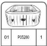

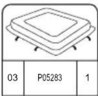


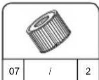
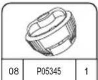

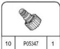
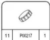

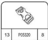

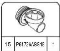

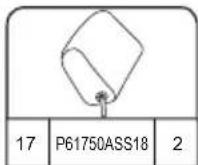
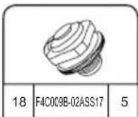


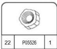


HAWAII HYDROJET PRO S200102 (60031)
— 1.80 m x 1.80 m x 71 cm / 71" x 71" x 28"

4 - 6 1.5-2°C/h

3-4°F/h

1,325 L/h
350 gal/h

1.2PSI 0.08Bar

795 L
210 gal

848 kg 1,869 Lb
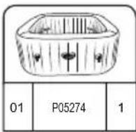


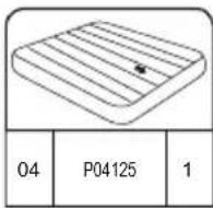
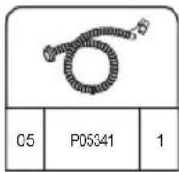


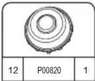

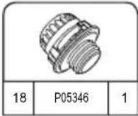


ΕΓΚΑΤΑΣΤΑΣΗ
natural_image
Simple line drawing of a folded fabric or material (no text or symbols)
natural_image
Diagram of a cable being inserted into an electronic device with connectors (no text or symbols)
natural_image
Line drawing of an electrical plug connected to a device with a circular warning symbol (no text or labels)4

flowchart
graph TD
    A["5 min. Pump"] --> B["Switch: 2.5"]
    B --> C["Power Button: 5.25"]
    C --> D["Digital Display: 2.89"]
    D --> E["Time Measurement: 5 min."]

5 min.

text_image
Maldives A B C5.25.1

natural_image
Diagram showing two rectangular plates with a curved arrow pointing downward from one to the other (no text or symbols)6

text_image
Diagram illustrating a medical procedure for using a pressure monitor, showing step-by-step instructions and validation outcomes.7

natural_image
Line drawing of a mechanical device with hoses and connectors, no text or symbols present8

natural_image
Line drawing of a portable device with a hand panel and a walkie-talkie, showing no text or symbols.9
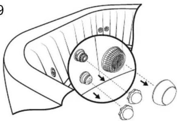
natural_image
Diagram of a mechanical component with internal gears and a magnified inset showing internal structure (no text or labels)10

natural_image
Diagram showing a device with a magnified inset of internal components, no text or symbols present11

text_image
MAX. MIN.PRCD T-ΣET
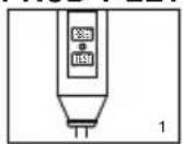
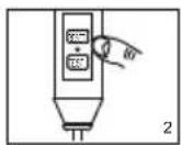
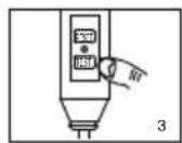
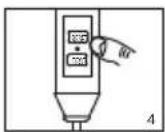
text_image
Technical diagram showing a device with labeled components and a close-up of a component with an arrow indicating direction.natural_image
Line drawing of an electronic device with connectors and wiring, no text or symbols presentΧΡΗΣΗ ΤΟΥ ΣΠΑ

natural_image
Technical line drawing of a mechanical device with no visible text or symbols
natural_image
Technical line drawing of a mechanical device with no visible text or symbols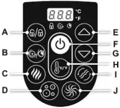
text_image
A B C D 8.8.8 °C °F E F G H I Jtext_image
Diagram illustrating hand manipulation of a flower with directional arrows and polarity signs
text_image
Diagram showing a device emitting heat from a box, with a magnified inset highlighting internal components.natural_image
Illustration of a baby bottle with internal compartments and a close-up of the bottle's internal structure (no text or symbols)natural_image
Exploded view diagram of a mechanical component showing internal parts and assembly (no text or labels)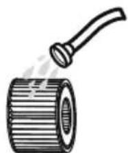
natural_image
Illustration of a cylindrical pipe with a handle emitting steam (no text or symbols)ΣΥΝΤΗΡΗΣΗ ΝΕΡΟΥ
text_image
Diagram illustrating a mechanical assembly process with labeled parts and a magnified detail showing internal components.natural_image
Illustration of a hot air stove with a fan emitting smoke, connected to a small vehicle (no text or symbols)natural_image
Diagram of a device with a close-up view showing internal components (no text or symbols)
text_image
P053473.4.

text_image
4.
natural_image
Diagram of a biological structure with arrows indicating internal components and a magnified inset showing circular elements (no text or labels)5.6.

natural_image
Line drawing of a device with a hand panel connected to a battery pack, showing internal components and an arrow indicating direction (no text or symbols)
text_image
Diagram illustrating a mechanical assembly process with labeled parts and a magnified view showing a component being processed.
natural_image
Line drawing of a portable electronic device with connectors and a cable (no text or symbols)natural_image
Abstract geometric diagram with overlapping planes and shaded regions (no text or symbols)MALDIVES HYDROJET PRO S200102 (60033)
— 2.01 m x 2.01 m x 80 cm / 79" x 79" x 31.5"

5 - 7 1-1.5°C/h

2-3°F/h

1,325 L/h
350 gal/h

1.2PSI 0.08Bar

1050 L
277 gal

1118 kg
2,465 Lb


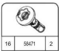
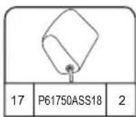


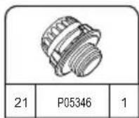


HAWAII HYDROJET PRO S200102 (60031)
— 1.80 m x 1.80 m x 71 cm / 71" x 71" x 28"

4 - 6 1.5-2°C/h

3-4°F/h

1,325 L/h
350 gal/h

1.2PSI 0.08Bar
795 L
210 gal

848 kg 1,869 Lb


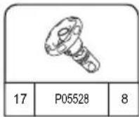


УСТАНОВКА
natural_image
Simple line drawing of a folded fabric or material (no text or symbols)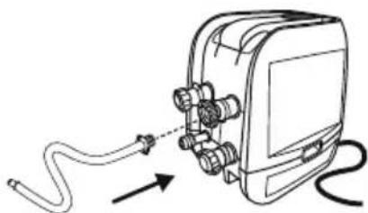
natural_image
Diagram of a cable being inserted into an electronic device with connectors (no text or symbols)
natural_image
Line drawing of an electrical plug connected to a device with a circular warning symbol (no text or labels)4
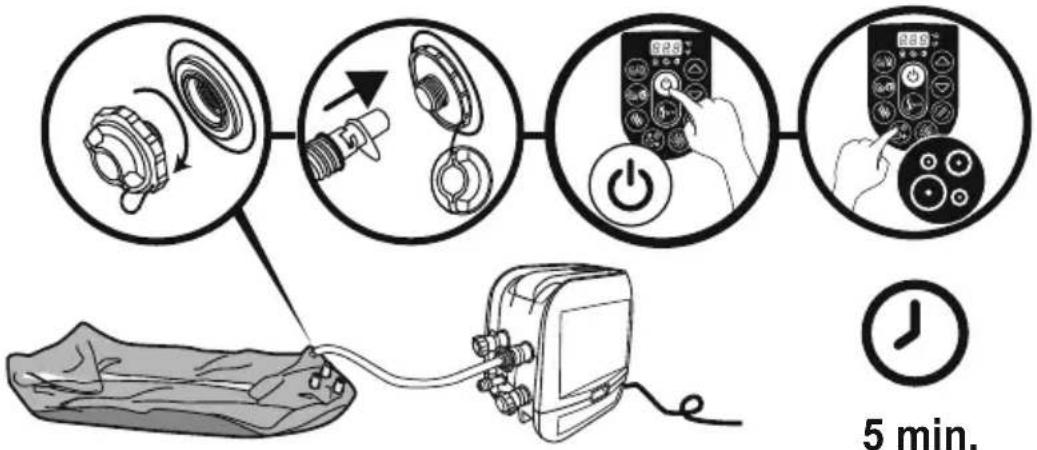
flowchart
graph TD
    A["5 min. Pump"] --> B["Switch: 2.5"]
    B --> C["Power Button: 5.25"]
    C --> D["Digital Display: 2.89"]
    D --> E["Time Measurement: 5 min."]

5 min.

text_image
Maldives A B C5.25.1

natural_image
Diagram showing two rectangular plates with a curved arrow pointing downward from one to the other (no text or symbols)6

text_image
Diagram illustrating a medical procedure for using a pressure monitor, showing step-by-step instructions and validation outcomes.7

natural_image
Line drawing of a mechanical device with hoses and connectors, no text or symbols present8
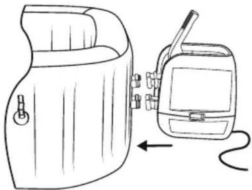
natural_image
Line drawing of a portable device with a hand panel and a walkie-talkie, showing no text or symbols.9

natural_image
Diagram of a mechanical component with internal gear and mesh structure, showing alignment and dislocation (no text or symbols)10

natural_image
Diagram showing a device with a magnified inset of three circular components, no text or symbols present.11

text_image
MAX. MIN.text_image
Technical diagram showing a device with labeled components and a close-up of a component detail with directional arrows.natural_image
Line drawing of an electronic device with connectors and wiring, no text or symbols presentnatural_image
Technical line drawing of a mechanical device with no visible text or symbols
natural_image
Technical line drawing of a mechanical device with no visible text or symbols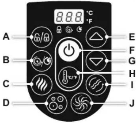
text_image
A B C D 8.8.8 °C °F E F G H I Jtext_image
Diagram illustrating hand manipulation of a flower with directional arrows and polarity signs
text_image
Diagram showing a device emitting heat from a container with labeled components and smoke emissionnatural_image
Illustration of a medical device with labeled parts including a basin, capsule, and digital meter (no text or symbols present)Обслуживание крышки
text_image
Diagram illustrating a mechanical assembly process with labeled parts and directional arrows, including a magnified inset showing internal components.natural_image
Illustration of a hot box connected to a device with a circular fan-like pattern (no text or symbols)natural_image
Diagram of a device with a close-up inset showing internal components (no text or symbols)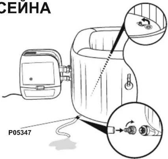
text_image
СЕЙНА P053473.4.

text_image
4.
natural_image
Diagram of a biological structure with arrows indicating internal components and a magnified inset showing circular elements (no text or labels)5.6.

natural_image
Line drawing of a portable device with a hand panel and a separate device with a cable, both without any text or symbols.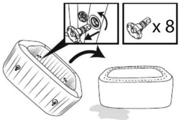
text_image
Diagram illustrating a mechanical assembly process with labeled parts and a magnified view showing a component being processed.
natural_image
Line drawing of a portable electronic device with connectors and a cable (no text or symbols)natural_image
Abstract geometric diagram with overlapping planes and shaded regions (no text or symbols)MALDIVES HYDROJET PRO S200102 (60033)
— 2.01 m x 2.01 m x 80 cm / 79" x 79" x 31.5"

5 - 7 1-1.5°C/h

2-3°F/h

1,325 L/h
350 gal/h

1.2PSI 0.08Bar
1050 L
277 gal

1118 kg
2,465 Lb
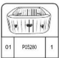


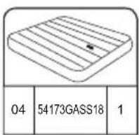

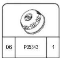
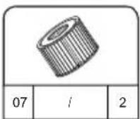


HAWAII HYDROJET PRO S200102 (60031)
— 1.80 m x 1.80 m x 71 cm / 71" x 71" x 28"

4 - 6 1.5-2°C/h

3-4°F/h

1,325 L/h
350 gal/h

1.2PSI 0.08Bar

795 L
210 gal

848 kg 1,869 Lb

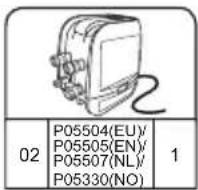


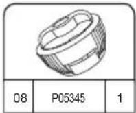


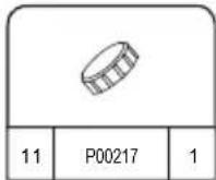


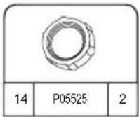


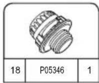

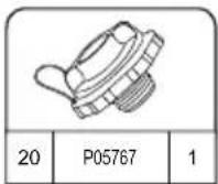
MONTAŻ

INSTRUKCJA
MONTAŻU ZIMAĄ

text_image
< 10°C(50°F)
text_image
>15°C(59°F) >15°C(59°F)natural_image
Simple line drawing of a folded fabric or material (no text or symbols)
natural_image
Diagram of a cable being inserted into an electronic device (no text or symbols present)
natural_image
Line drawing of an electrical plug connected to a device with a circular warning symbol (no text or labels)4

flowchart
graph TD
    A["5 min. Pump"] --> B["Switch: 2.5"]
    B --> C["Power Button: 5.25"]
    C --> D["Digital Display: 2.89"]
    D --> E["Time Measurement: 5 min."]

5 min.

text_image
Maldives A B C5.25.1

natural_image
Diagram showing two rectangular blocks with a curved arrow pointing downward from one to the other (no text or symbols)6

text_image
Diagram illustrating a medical procedure for using a pressure monitor, showing step-by-step instructions and validation outcomes.7

natural_image
Line drawing of a handheld electronic device with hoses and connectors, no text or symbols present8

natural_image
Line drawing of a portable device with a hand panel and a walkie-talkie, showing no text or symbols.9

natural_image
Diagram of a mechanical component with internal gears and a magnified inset showing internal structure (no text or labels)10

natural_image
Diagram of a mechanical component with a magnified inset showing internal components (no text or symbols)11

text_image
MAX. MIN.16
PRCD Test
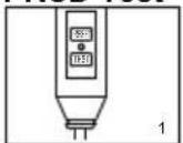


text_image
Technical diagram showing a device with labeled components and a close-up of a component detail with an arrow indicating direction.natural_image
Line drawing of an electronic device with connectors and wiring, no text or symbols presentKORZYSTANIE Z SPA

natural_image
Technical line drawing of a mechanical device with no visible text or symbols
natural_image
Technical line drawing of a mechanical device with no visible text or symbols
text_image
A B C D 8.8.8 °C °F E F G H I Jtext_image
Diagram illustrating hand positioning and movement of a flower, showing correct (+) and incorrect (-) states with directional arrows.
text_image
Diagram showing a device emitting heat from a device with labeled components and a magnified inset highlighting internal components.natural_image
Exploded view diagram of a mechanical component showing internal parts and assembly (no text or labels)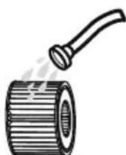
natural_image
Illustration of a cylindrical pipe with a handle emitting vapor (no text or symbols)Utrzymanie wody
text_image
Diagram illustrating a mechanical assembly process with labeled parts and directional arrows, including a magnified inset showing internal components.natural_image
Illustration of a hot water bath connected to a device with a circular inset showing a fan-like pattern (no text or symbols)natural_image
Diagram of a device with a close-up view showing internal components (no text or symbols)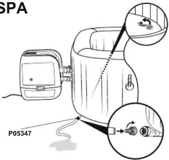
text_image
SPA P053473.4.

text_image
4.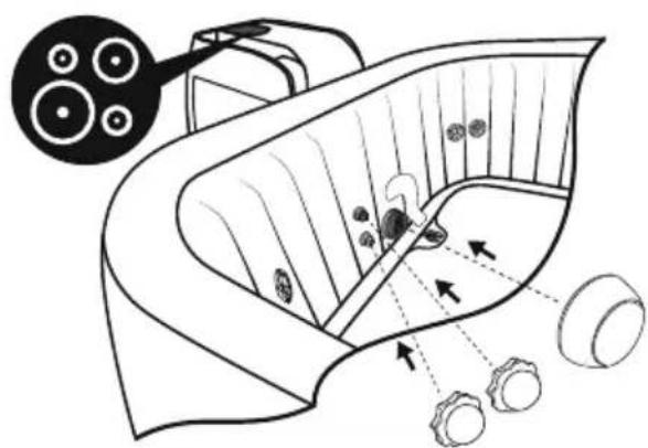
natural_image
Diagram of a biological structure with arrows indicating internal components and a magnified inset showing circular elements (no text or labels)5.6.

natural_image
Line drawing of a portable device with a hand panel and a digital device connected to it, showing no text or symbols.
text_image
Diagram illustrating a mechanical assembly process with labeled parts and a magnified view showing a component being processed.
natural_image
Line drawing of a portable electronic device with connectors and a cable (no text or symbols)natural_image
Abstract geometric diagram with overlapping planes and shaded regions (no text or symbols)MALDIVES HYDROJET PRO S200102 (60033)
— 2.01 m x 2.01 m x 80 cm / 79" x 79" x 31.5"

5 - 7 1-1.5°C/h

2-3°F/h

1,325 L/h
350 gal/h

1.2PSI 0.08Bar

1050 L
277 gal

1118 kg
2,465 Lb
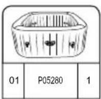
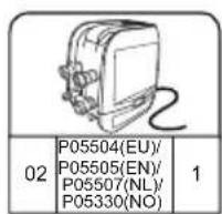

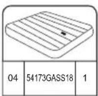


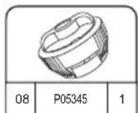

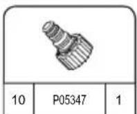
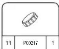


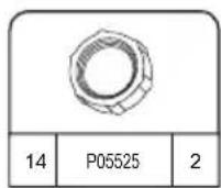

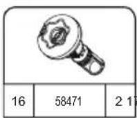
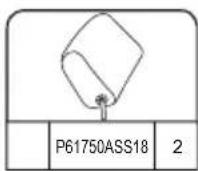

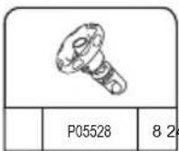
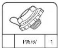
HAWAII HYDROJET PRO S200102 (60031)
— 1.80 m x 1.80 m x 71 cm / 71" x 71" x 28"

4 - 6 1.5-2°C/h

3-4°F/h

1,325 L/h
350 gal/h

1.2PSI 0.08Bar

795 L
210 gal

848 kg 1,869 Lb


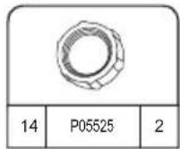


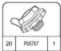
FELÁLLÍTÁS
natural_image
Simple line drawing of a folded fabric or material (no text or symbols)
natural_image
Diagram of a cable being inserted into an electronic device (no text or symbols present)
natural_image
Line drawing of an electrical plug connected to a device with a circular warning symbol (no text or labels)4

flowchart
graph TD
    A["5 min. Pump"] --> B["Switch: 2.5"]
    B --> C["Power Button: 5.25"]
    C --> D["Digital Display: 2.89"]
    D --> E["Time Measurement: 5 min."]

5 min.

text_image
Maldives A B C5.25.1
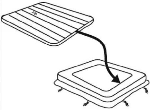
natural_image
Diagram showing two rectangular blocks with a curved arrow pointing downward from one to the other (no text or symbols)6

text_image
Diagram illustrating a medical procedure for using a pressure monitor, showing step-by-step instructions and validation outcomes.78

natural_image
Line drawing of a handheld electronic device with hoses and connectors, no text or symbols present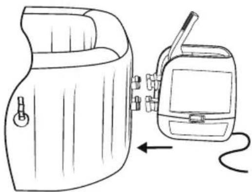
natural_image
Line drawing of a device with a hand panel and a handheld device connected by a cable (no text or symbols)9
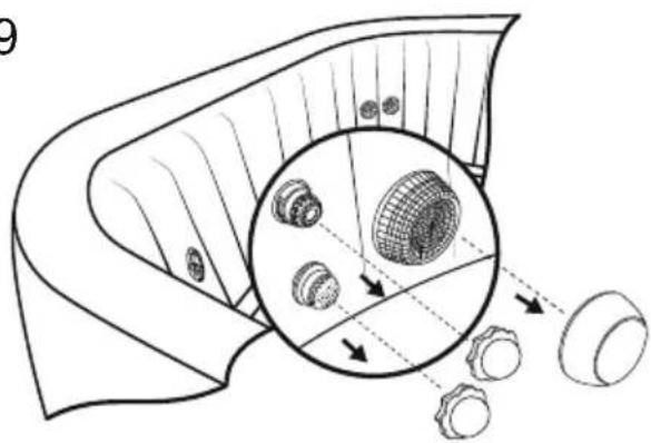
natural_image
Diagram of a mechanical component with internal gears and a magnified inset showing internal structure (no text or labels)10

natural_image
Diagram of a mechanical component with a magnified inset showing internal components (no text or symbols)11

text_image
MAX. MIN.PRCD teszt
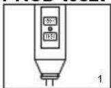
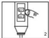


text_image
Technical diagram showing a device with labeled components and a close-up of a component detail with an arrow indicating direction.natural_image
Line drawing of an electronic device with connectors and wiring, no text or symbols presentA FÜRDŐ HASZNÁLATA

natural_image
Technical line drawing of a mechanical device with no visible text or symbols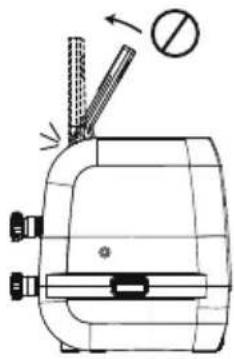
natural_image
Technical line drawing of a mechanical device with no visible text or symbols
text_image
A B C D 8.8.8 °C °F E F G H I Jtext_image
Diagram illustrating hand positioning and movement of a mechanical component, showing positive and negative rotation directions.
text_image
Diagram showing a device emitting heat from a device with a magnified inset highlighting internal components.natural_image
Simple line drawing of a hot water bath connected to a device with a circular inset showing a fan-like pattern (no text or symbols)natural_image
Diagram of a device with a close-up view showing internal components (no text or symbols)
text_image
P053473.4.

text_image
4.
natural_image
Diagram of a biological structure with cellular components and directional arrows, no text or symbols present5.6.

natural_image
Line drawing of a portable device next to a handheld device with a cable, showing no text or symbols.
text_image
Diagram illustrating a mechanical assembly process with labeled parts and magnified detail view
natural_image
Line drawing of a portable electronic device with connectors and a cable (no text or symbols)CHECKLISTA INNAN UPPSTÄLLNING
KONTROLLERA DELAR
natural_image
Abstract geometric diagram with overlapping planes and shaded regions (no text or symbols)MALDIVES HYDROJET PRO S200102 (60033)
— 2.01 m x 2.01 m x 80 cm / 79" x 79" x 31.5"

5 - 7 1-1.5°C/h

2-3°F/h

1,325 L/h
350 gal/h

1.2PSI 0.08Bar

1050 L
277 gal

1118 kg
2,465 Lb

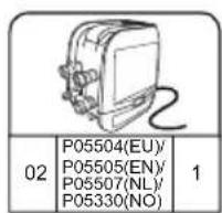
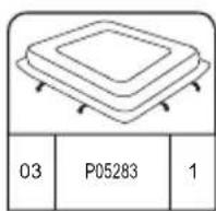


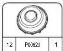


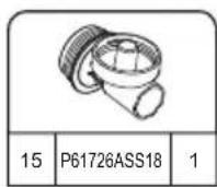


HAWAII HYDROJET PRO S200102 (60031)
— 1.80 m x 1.80 m x 71 cm / 71" x 71" x 28"

4 - 6 1.5-2°C/h

3-4°F/h

1,325 L/h
350 gal/h

1.2PSI 0.08Bar

795 L
210 gal

848 kg 1,869 Lb


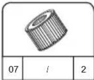

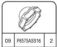


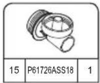
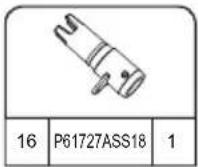


INSTALLATION

UPPSTÄLLNINGSINSTRUKTIONER
PÅ VINTERN

text_image
< 10°C(50°F)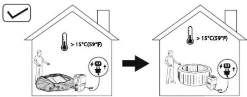
text_image
> 15°C(59°F) > 15°C(59°F)natural_image
Simple line drawing of a folded fabric or material (no text or symbols)
natural_image
Diagram of a medical device with tubing and connectors, showing no text or symbols
natural_image
Line drawing of an electrical plug connected to a device with a circular warning symbol (no text or labels)4

flowchart
graph TD
    A["5 min. Pump"] --> B["Step 1: Internal pump assembly with rotating wheel"]
    B --> C["Step 2: Display device with power button and screen"]
    C --> D["Step 3: Handheld device with 'S25' on screen"]
    D --> E["Step 4: Display device with '289' on screen"]

5 min.

text_image
Maldives A B C5.25.1

natural_image
Diagram showing two rectangular blocks with a curved arrow pointing downward from one to the other (no text or symbols)6

text_image
Diagram illustrating a medical procedure for using a pressure monitor, showing step-by-step instructions and validation outcomes.7

natural_image
Line drawing of a handheld electronic device with hoses and connectors, no text or symbols present8

natural_image
Line drawing of a portable device with a hand panel and a walkie-talkie, showing no text or symbols.9

natural_image
Diagram of a mechanical component with internal gears and a magnified inset showing internal structure (no text or labels)10

natural_image
Diagram of a mechanical component with a magnified inset showing internal components (no text or symbols)11

text_image
MAX. MIN.16
Test jordfelsbrytare
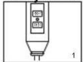
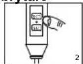

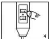
text_image
Technical diagram showing a device with labeled components and a close-up of a component detail with an arrow indicating direction.natural_image
Line drawing of an electronic device with wires and connectors, no text or symbols presentANVÄNDNING AV SPAT
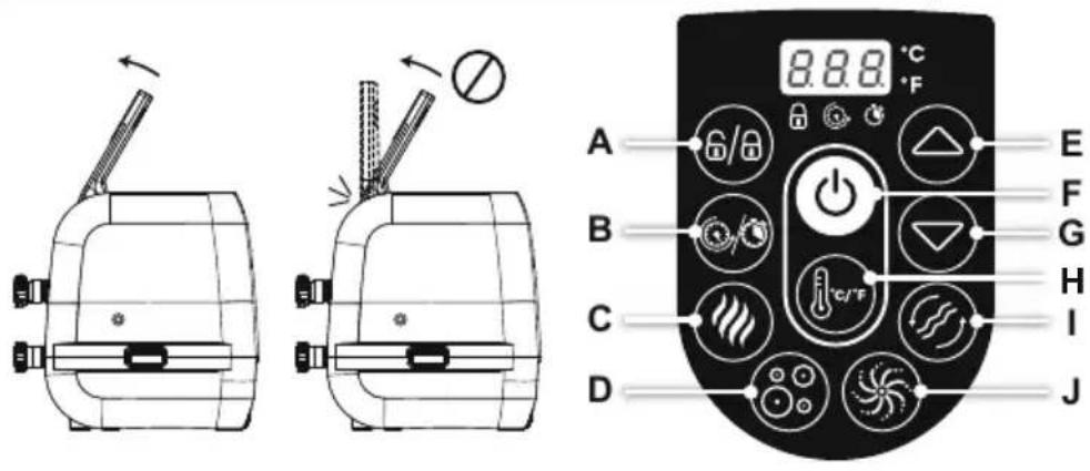
text_image
8.8.8 °C A 6/8 B C D E F G H I Jtext_image
Diagram illustrating hand manipulation or disassembly process with labeled arrows and plus/minus signs indicating movement direction
text_image
Diagram showing a device emitting heat from a container with a magnified inset highlighting internal components.natural_image
Illustration of a hot water bath connected to a device with a circular pattern (no text or symbols)natural_image
Diagram of a device with a close-up view showing internal components (no text or symbols)
text_image
P053473.4.

text_image
4.
natural_image
Diagram of a biological structure with cellular layers and directional arrows, no text or symbols present5.6.

natural_image
Line drawing of a portable device with a hand panel and a separate device, both shown in line with an arrow indicating direction (no text or symbols present)
text_image
Diagram illustrating a mechanical assembly process with magnified detail and 8x magnification view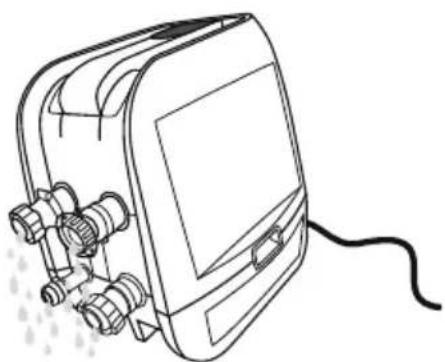
natural_image
Line drawing of a portable electronic device with connectors and a cable (no text or symbols)For support please visit us at:
bestwaycorp.com/support
©2020 Bestway Inflatables & Material Corp.
All rights reserved/Tous droits réservés/Todos los derechos reservados/Alle Rechte vorbehalten/Tutti i diritti riservati ®™ Trademarks used in some countries under license to/
Bestway Inflatables & Material Corp., No.3065 Cao An Road, Shanghai, 201812, China.
Manufactured, distributed and represented in the European Union by/
Bestway (USA) Inc., 3411 E. Harbour Drive, Phoenix, Arizona 85034, United States of America
Tel: +86 21 69135588 (For U.S. and Canada)
Distributed in Australia & New Zealand by Bestway Australia Pty Ltd, Unit 2/98-104 Carnarvon St Silverwater, NSW 2128, Australia
Tel: Australia: (+61) 29 0371 388; New Zealand: 0800 142 101
Exported by/Exporté par/Exportado por/Exportiert von/Esportato da
Bestway (Hong Kong) International Ltd./Bestway Enterprise Company Limited
Suite 713, 7/Floor, East Wing, Tsim Sha Tsui Centre, 66 Mody Road, Kowloon, Hong Kong
www.bestwaycorp.com