Storm 2420 - Snow blower TROY-BILT - Free user manual and instructions
Find the device manual for free Storm 2420 TROY-BILT in PDF.
| Product Type | Two-stage snow blower |
| Brand | Troy-Bilt |
| Model | Storm 2420 |
| Clearing Width | 61 cm (24 in) |
| Intake Height | 53 cm (21 in) |
| Engine | 4-cycle, 208 cc |
| Fuel Tank Capacity | 1.9 L (0.5 US gal) |
| Starting | Electric (with wireless battery) and recoil starter |
| Transmission | Hydrostatic or 6-speed (depending on version) |
| Chute Control | Manual or electric (depending on version) |
| Headlight | Integrated (turns on automatically with engine) |
| Heated Handles | Optional (ON/OFF switch) |
| Chute Clearing Tool | Included (attached to back of auger housing) |
| Skid Shoes | Adjustable (for gravel or smooth surface) |
| Scraper Blade | Adjustable (two positions) |
| Cutting Bars | Removable and adjustable (optional) |
| Recommended Tire Pressure | Indicated on tire sidewall |
| Weight | Approximately 113 kg (250 lb) |
| Warranty | 3 years |
Frequently Asked Questions - Storm 2420 TROY-BILT
User questions about Storm 2420 TROY-BILT
0 question about this device. Answer the ones you know or ask your own.
Ask a new question about this device
Download the instructions for your Snow blower in PDF format for free! Find your manual Storm 2420 - TROY-BILT and take your electronic device back in hand. On this page are published all the documents necessary for the use of your device. Storm 2420 by TROY-BILT.
USER MANUAL Storm 2420 TROY-BILT
French (Français) Page 65
Record Product Information
Before setting up and operating your new snowblower, please locate the model plate on the engine and record the information in the provided area to the right. You can locate the model plate by standing at the operator's position and looking at the rear, right side of the engine. This information will be necessary, should you seek technical support via our web site, Customer Support Department, or with a local authorized service dealer.
Model Number
Serial Number
WARNING
Read and follow all safety rules and instructions in this manual before attempting to operate this machine.
Failure to comply with these instructions may result in personal injury - SAVE THESE INSTRUCTIONS.
WARNING
CALIFORNIA PROPOSITION 65
Engine Exhaust, some of its constituents, and certain vehicle components contain or emit chemicals known to State of California to cause cancer and birth defects or other reproductive harm.
NOTE: This Operator's Manual covers several models. Features may vary by model. Not all features in this manual are applicable to all models and the model depicted may differ from yours.
WARNING

This symbol points out important safety instructions which, if not followed, could endanger the personal safety and/or property of yourself and others. Read and follow all instructions in this manual before attempting to operate this machine. Failure to comply with these instructions may result in personal injury.
When you see this symbol, HEED ITS WARNING!
DANGER
This machine was built to be operated according to the safe operation practices in this manual. As with any type of power equipment, carelessness or error on the part of the operator can result in serious injury. This machine is capable of amputating fingers, hands, toes and feet and throwing debris. Failure to observe the following safety instructions could result in serious injury or death.
Training
- Read, understand, and follow all instructions on the machine and in the manual(s) before attempting to assemble and operate. Keep this manual in a safe place for future and regular reference and for ordering replacement parts.
- Be familiar with all controls and their proper operation. Know how to stop the machine and disengage them quickly.
- Never allow children under 14 years of age to operate this machine. Children 14 and over should read and understand the instructions and safe operation practices in this manual and on the machine and be trained and supervised by an adult.
- Never allow adults to operate this machine without proper instruction.
- Thrown objects can cause serious personal injury. Plan your snow-blowing pattern to avoid discharge of material toward roads, bystanders and the like.
- Keep bystanders, pets and children at least 75 feet from the machine while it is in operation. Stop machine if anyone enters the area.
- Exercise caution to avoid slipping or falling, especially when operating in reverse.
Preparation
Thoroughly inspect the area where the equipment is to be used. Remove all doormats, newspapers, sleds, boards, wires and other foreign objects, which could be tripped over or thrown by the machine.
- Always wear safety glasses or eye shields during operation and while performing an adjustment or repair to protect your eyes. Thrown objects which ricochet can cause serious injury to the eyes.
- Do not operate without wearing adequate winter outer garments. Do not wear jewelry, long scarves or other loose clothing, which could become entangled in moving parts. Wear footwear which will improve footing on slippery surfaces.
- Use a grounded three-wire extension cord and receptacle for all machines with electric start engines.
- Adjust auger housing height to clear gravel or crushed rock surfaces.
- Disengage all control levers before starting the engine.
- Never attempt to make any adjustments while engine is running, except where specifically recommended in the operator's manual.
- Let engine and machine adjust to outdoor temperature before starting to clear snow.
Safe Handling of Gasoline
To avoid personal injury or property damage use extreme care in handling gasoline. Gasoline is extremely flammable and the vapors are explosive. Serious personal injury can occur when gasoline is spilled on yourself or your clothes which can ignite. Wash your skin and change clothes immediately.
- Use only an approved gasoline container.
- Extinguish all cigarettes, cigars, pipes and other sources of ignition.
- Never fuel machine indoors.
- Never remove gas cap or add fuel while the engine is hot or running.
- Allow engine to cool at least 5 minutes before refueling.
-
Never over fill fuel tank. Fill tank to no more than 12 inch below bottom of filler neck to provide space for fuel expansion.
-
Replace gasoline cap and tighten securely.
-
If gasoline is spilled, wipe it off the engine and equipment. Move machine to another area. Wait 5 minutes before starting the engine. If fuel is spilled on clothing, change clothing immediately.
-
Never store the machine or fuel container inside where there is an open flame, spark or pilot light (e.g. furnace, water heater, space heater, clothes dryer etc.).
-
Allow machine to cool at least 5 minutes before storing.
-
Never fill containers inside a vehicle or on a truck or trailer bed with a plastic liner. Always place containers on the ground away from your vehicle before filling.
-
If possible, remove gas-powered equipment from the truck or trailer and refuel it on the ground. If this is not possible, then refuel such equipment on a trailer with a portable container, rather than from a gasoline dispenser nozzle.
-
Keep the nozzle in contact with the rim of the fuel tank or container opening at all times until fueling is complete. Do not use a nozzle lock-open device.
Operation
- Do not put hands or feet near rotating parts, in the auger housing or chute assembly. Contact with the rotating parts can amputate hands and feet.
- The auger control lever is a safety device. Never bypass its operation. Doing so makes the machine unsafe and may cause personal injury.
- The control levers must operate easily in both directions and automatically return to the disengaged position when released.
- Never operate with a missing or damaged chute assembly. Keep all safety devices in place and working.
- Never run an engine indoors or in a poorly ventilated area. Engine exhaust contains carbon monoxide, an odorless and deadly gas.
- Do not operate machine while under the influence of alcohol or drugs.
- Muffler and engine become hot and can cause a burn. Do not touch. Keep children away.
- Exercise extreme caution when operating on or crossing gravel surfaces. Stay alert for hidden hazards or traffic.
- Exercise caution when changing direction and while operating on slopes. Do not operate on steep slopes.
- Plan your snow-blowing pattern to avoid discharge towards windows, walls, cars etc. Thus, avoiding possible property damage or personal injury caused by a ricochet.
- Never direct discharge at children, bystanders and pets or allow anyone in front of the machine.
- Do not overload machine capacity by attempting to clear snow at too fast of a rate.
- Never operate this machine without good visibility or light. Always be sure of your footing and keep a firm hold on the handles. Walk, never run.
- Release auger control lever to disengage power to the auger when transporting or not clearing snow.
-
Never operate machine at high transport speeds on slippery surfaces. Look down and behind and use care when backing up.
-
After striking a foreign object or if the machine should start to vibrate abnormally, stop the engine, remove the safety key or disconnect spark plug wire. Inspect thoroughly for damage. Repair any damage before starting and operating.
- Disengage all control levers, stop engine, remove the safety key or disconnect spark plug wire before you leave the operating position (behind the handles). Wait until the auger comes to a complete stop before unclogging the chute assembly, making any adjustments, or inspections.
- Never put your hand in the discharge or collector openings. Always use the clean-out tool provided to unclog the discharge opening. Do not unclog chute assembly while engine is running. Shut off engine, remove the safety key or disconnect spark plug wire. Remain behind handles until all moving parts have stopped before unclogging.
- Use only attachments and accessories approved by the manufacturer (e.g. wheel weights, tire chains, cabs etc.).
- When starting engine, pull cord slowly until resistance is felt, then pull rapidly. Rapid retraction of starter cord (kickback) will pull hand and arm toward engine faster than you can let go. Broken bones, fractures, bruises or sprains could result.
- If situations occur which are not covered in this manual, use care and good judgment. Contact Customer Support for assistance and the name of your nearest servicing dealer.
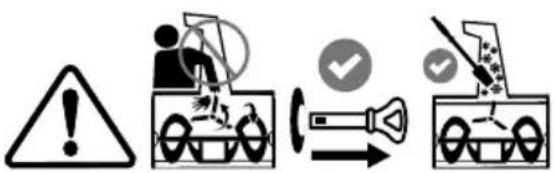
Clearing a Clogged Discharge Chute
Hand contact with the rotating impeller or auger inside the discharge chute is the most common cause of injury associated with snow blowers. Never use your hand to clean out the discharge chute.
To clear the chute:
- SHUT THE ENGINE OFF!
- Remove the safety key or disconnect spark plug wire.
- Wait 10 seconds to be sure the impeller or auger has stopped rotating.
- Always use a clean-out tool, not your hands.
Maintenance & Storage
- Never tamper with safety devices. Check their proper operation regularly. Refer to the maintenance and adjustment sections of this manual.
- Before cleaning, repairing, or inspecting machine, disengage all control levers, stop the engine, remove the safety key or disconnect spark plug wire. Wait until the auger comes to a complete stop.
-
Check bolts and screws for proper tightness at frequent intervals to keep the machine in safe working condition. Also, visually inspect machine for any damage.
-
Do not change the engine governor setting or over-speed the engine. The governor controls the maximum safe operating speed of the engine.
- Snow blower shave plates and skid shoes are subject to wear and damage. For your safety protection, frequently check all components and replace with original equipment manufacturer's (OEM) parts only. "Use of parts which do not meet the original equipment specifications may lead to improper performance and compromise safety!"
- Check control levers periodically to verify they engage and disengage properly and adjust, if necessary. Refer to the adjustment section in this operator's manual for instructions.
- Maintain or replace safety and instruction labels, as necessary.
- Observe proper disposal laws and regulations for gas, oil, etc. to protect the environment.
- Prior to storing, run machine a few minutes to clear snow from machine and prevent freeze up of auger.
- Never store the machine or fuel container inside where there is an open flame, spark or pilot light such as a water heater, furnace, clothes dryer, etc.
- Always refer to the operator's manual for proper instructions on off-season storage.
- Check fuel line, tank, cap, and fittings frequently for cracks or leaks. Replace if necessary.
- Do not crank engine with spark plug removed.
- According to the Consumer Products Safety Commission (CPSC) and the U.S. Environmental Protection Agency (EPA), this product has an Average Useful Life of seven (7) years, or 60 hours of operation. At the end of the Average Useful Life have the machine inspected annually by an authorized service dealer to ensure that all mechanical and safety systems are working properly and not worn excessively. Failure to do so can result in accidents, injuries or death.
Do not modify engine
To avoid serious injury or death, do not modify engine in any way. Tampering with the governor setting can lead to a runaway engine and cause it to operate at unsafe speeds. Never tamper with factory setting of engine governor.
Notice Regarding Emissions
Engines which are certified to comply with California and federal EPA emission regulations for SORE (Small Off Road Equipment) are certified to operate on regular unleaded gasoline, and may include the following emission control systems: Engine Modification (EM), Oxidizing Catalyst (OC), Secondary Air Injection (SAI) and Three Way Catalyst (TWC) if so equipped.
SAFETY SYMBOLS
This page depicts and describes safety symbols that may appear on the snow blower and engine. Read, understand, and follow all warnings and instructions on the snow blower and engine, along with the operator's manuals before attempting to operate.
| Symbol Description | |
 OPESymbol.com OPESymbol.com | WARNING - READ OPERATOR'S MANUAL: Read, understand and follow all the safety rules and instructions in the manual(s) and on the snow blower before attempting to operate this snow blower. Failure to comply with this information may result in personal injury or death. Keep this manual in a safe location for future and regular reference. Using a Smart Phone, scan the QR code symbol to learn more information concerning the warnings contained on this snow blower. You can also go to www.OPESymbol.com for more information. |
 | WARNING - AVOID AMPUTATION INJURY, DISCHARGE CHUTE: Do not put hands near or into the discharge chute while the engine is running. Contact with the rotating impeller or auger can amputate fingers and hands. Stop engine and remove safety key and wait until all moving parts have stopped rotating. Always use clean-out tool to clear the discharge chute, never use your hand. |
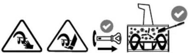 | WARNING - AVOID AMPUTATION INJURY, AUGER HOUSING: Do not put hands or feet near or into the auger housing while the engine is running. Contact with the auger can amputate fingers, hands, toes and feet. Stop engine and remove safety key and wait until all moving parts have stopped rotating. Always use clean-out tool to clear the auger housing, never use your hands. |
 | WARNING - ELECTRICAL SHOCK: Do not plug in and use the engine's electric starter in the rain or wet conditions. |
 | WARNING - GASOLINE IS FLAMMABLE: Allow the engine to cool at least five minutes before refueling. |
 | WARNING - CARBON MONOXIDE: Never run an engine indoors or in a poorly ventilated area. Engine exhaust contains carbon monoxide, an odorless and deadly gas. |
 | WARNING - HOT SURFACE: The muffler and engine become very hot and can cause serious burn injuries. Do not touch. Allow the snow blower to cool for at least five minutes before storing or attempting any service. |
WARNING
Your Responsibility - Restrict the use of the snow blower to persons who read, understand and follow all warnings and instructions on snow blower, along with the operator's manuals. - SAVE THESE INSTRUCTIONS!
OVERVIEW
- Remove packaging materials from snow blower and any loose items from the carton.
- Rotate Handle into the upright position. Refer to Handle Assembly.
• Install the chute. Refer to Chute Assembly Options. - Complete snow blower assembly according to model and equipment. Refer to Set-up.
- If necessary make adjustments to ensure proper snow blower operation. Refer to Adjustments.
- Add fuel and oil. Refer to the Engine Operator's Manual shipped with snow blower.
TOOLS REQUIRED
- Adjustable Wrench or Socket Set
- Needle Nose Pliers
HANDLE ASSEMBLY
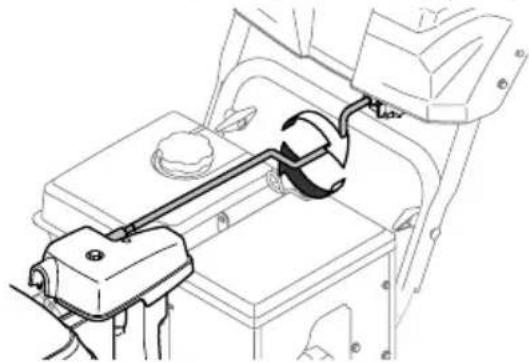
- Cut cable ties securing chute control rod or upper handle to the lower handle (if applicable), set aside the chute control rod (if applicable) and remove the wrap around the handles (if applicable).
NOTE: Do not cut the cable tie securing the control cables to the engine, if equipped.
NOTE: On models with Overhead Chute Control (with Flex Shaft), Four-Way Chute Control, and Electric Chute Control cut cable ties securing flex shaft to the lower handle and set the flex shaft aside. Remove rubber bands securing cables to carriage bolts and cut cable tie securing shift rod to lower handle. Refer to Figure 7 to help identify the control styles.
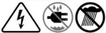
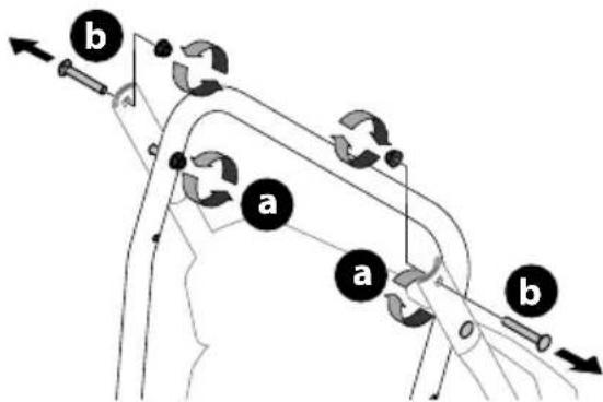
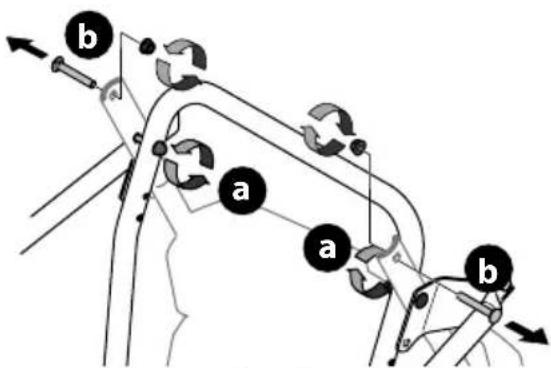
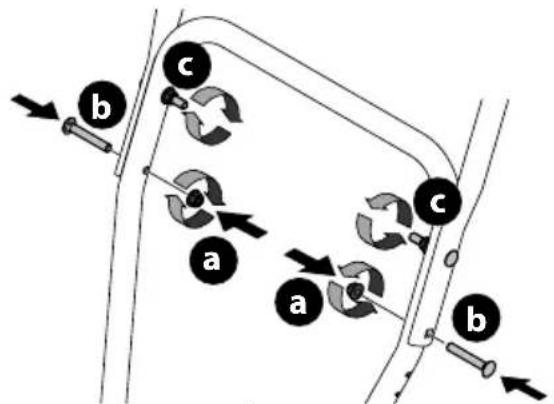
- Loosen the top two nuts (a) securing the upper and lower handle and remove the two carriage bolts (b) from the upper handle and set aside as shown in Figure 1 or Figure 2 for models with side supports.
flowchart
graph TD
    A["Component a"] --> B["Component b"]
    B --> C["Directional arrows indicating flow or movement"]
    style A fill:#f9f,stroke:#333
    style B fill:#ccf,stroke:#333
Figure 1
flowchart
graph TD
    A["Start"] --> B{Condition}
    B -->|Yes| C["a"]
    B -->|No| D["b"]
    C --> E["End"]
    D --> F["End"]
Figure 2
IMPORTANT: Place shift lever in Forward-6 position or fastest forward speed (if equipped).
- Observe lower rear area of equipment to be sure both cables (if equipped) are aligned and seated properly in roller guides (Figure 3).
NOTE: On select models, chute-pitch control cables will be routed under the engine on the left side and will not use roller guides.
natural_image
Mechanical assembly diagram showing two views of a vehicle's suspension components (no text or labels)Figure 3
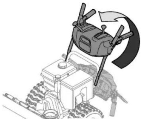
- Ensuring any cables, and wiring harness are clear of pivot points, Pivot handle upward and align the lower handle (Figure 4). Remove and discard any rubber bands, if present. They are for packaging purposes only.
natural_image
Illustration of a drone hovering above a tractor with a curved arrow indicating rotation (no text or symbols)Figure 4
NOTE: On select models with steel rod speed selectors, you may need to lower shift rod to the side slightly to maneuver handle panel over it when pivoting handle upward.
SET-UP
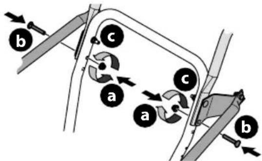
- Attach the two carriage bolts (b) and nuts (a) removed in Step 2. Finish securing the handle by tightening the top two nuts (c) loosened in Step 2. See Figure 5 or Figure 6 for models with side supports.
flowchart
graph TD
    A["Component a"] --> B["Component b"]
    B --> C["Component c"]
    C --> D["Arrow to a component"]
    style A fill:#f9f,stroke:#333
    style B fill:#ccf,stroke:#333
    style C fill:#cfc,stroke:#333
    style D fill:#fcc,stroke:#333
Figure 5
text_image
a b c a b cFigure 6
STOP
Refer to Figure 7 below to identify your "Chute Control Style" and continue to the "Assembly" instructions for your specific style on pages13 - 18.
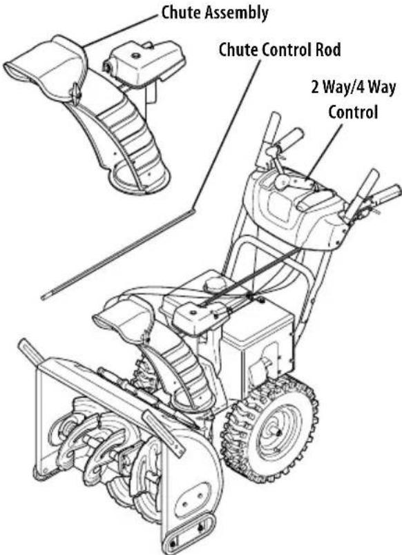
CHUTE CONTROL STYLES
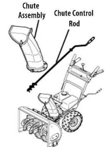
text_image
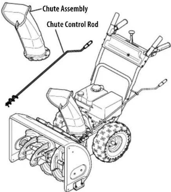
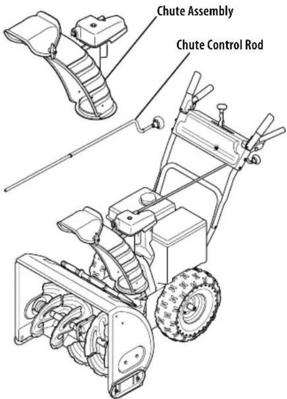
Chute Assembly Chute Control RodSide Mounted Chute Rotation Control w/ Manual Pitch on page 8
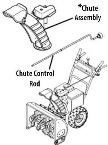
text_image
*Chute Assembly Chute Control RodOverhead Chute Rotation Control w/ Manual Pitch on page 8

text_image
*Chute Assembly 2-Way & 4-Way Chute Control Chute Control RodOverhead Chute Rotation Control w/ 2-Way Pitch or 4-Way Pitch & Rotation Control on page 9
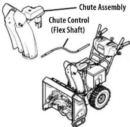
text_image
Chute Assembly Chute Control (Flex Shaft)Overhead Chute Control (Flex Shaft) w/ Steel Chute & 2-Way Pitch Control on page 11
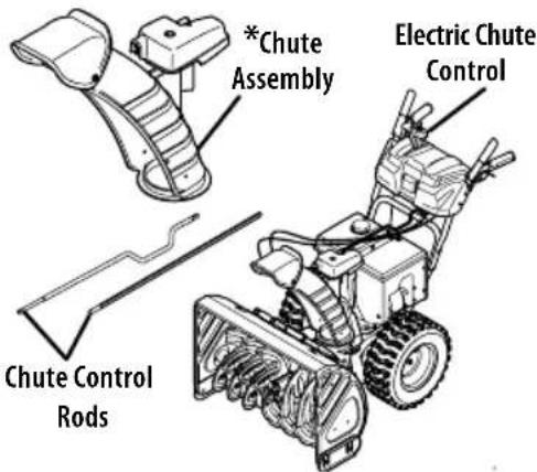
text_image
*Chute Assembly Electric Chute Control Chute Control RodsOverhead Chute Rotation Control w/ 4-Way Electric Pitch & Rotation Control on page 12
*NOTE: This model may be equipped with a metal chute assembly.
natural_image
Technical line drawing of a mechanical component with no visible text or symbolsFigure 7
SIDE MOUNTED CHUTE ROTATION CONTROL W/ MANUAL PITCH
text_image
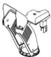
Chute Assembly Chute Control RodFigure 8
- Position chute assembly over base (Figure 9).
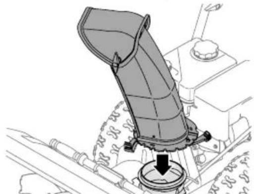
natural_image
Mechanical assembly diagram showing a lever mechanism with a downward arrow indicating motion (no text or symbols present)Figure 9
- Close flange keepers to secure chute assembly to chute base. Flange keepers will click into place when properly secured (Figure 10).
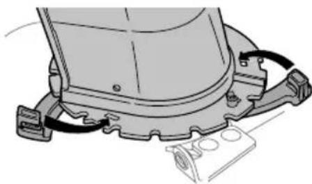
natural_image
Mechanical assembly diagram showing a component with attached parts and wiring (no text or symbols)Figure 10
NOTE: Ensure the lower chute is secured to the flange on the chute base. The lower edge of the chute keeper should be positioned below the flange on the chute base after being clicked into place. If flange keepers will not easily click into place, use palm of your hand to apply swift, firm pressure to the back of the keepers.
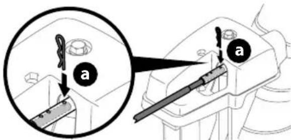
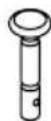
- Remove plastic cap (if present), flat washer (a) and hairpin clip (b) from end of chute control rod (Figure 11).
text_image
Technical diagram showing two mechanical assembly steps labeled a and b, with arrows indicating motion direction.Figure 11
- Insert end of chute control rod into lower bracket and secure with flat washer (a), hairpin clip (b) and plastic cap (if present) removed in Step 1. If necessary, lower bracket can be adjusted. Refer to Side Chute Control on page 16.
STOP
Continue to Set-Up (page 14).
OVERHEAD CHUTE ROTATION CONTROL W/ MANUAL PITCH
text_image
Chute Assembly Chute Control RodFigure 12
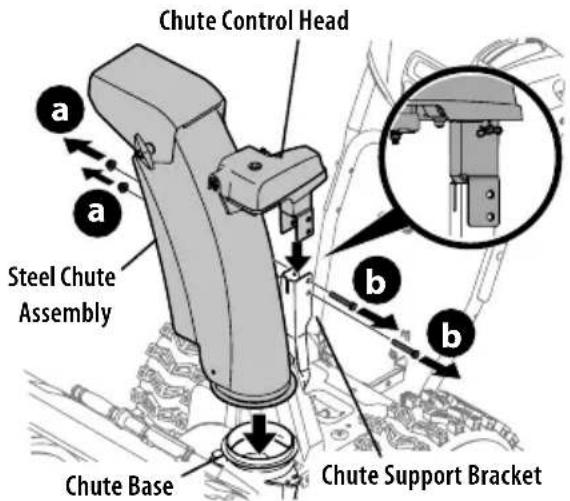
NOTE: If equipped with a metal chute assembly - This assembly will install the same as the standard chute shown in the figures of this procedure.
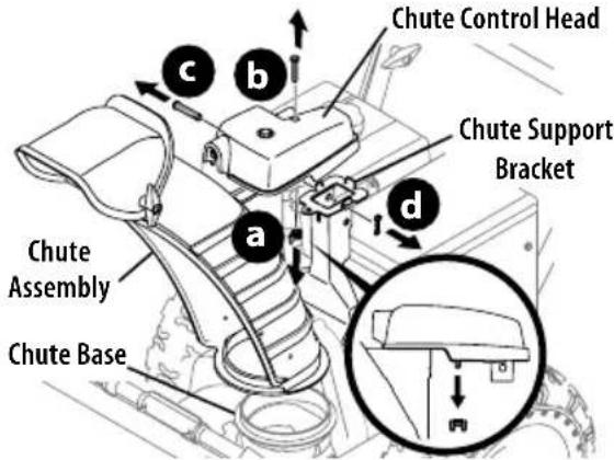
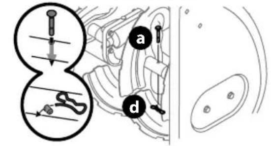
- Remove wing nut (or locknut if equipped) (a) and hex screw (b) from chute control head and clevis pin (c) and cotter pin (d) from chute support bracket. Position chute assembly (forward-facing) over chute base and chute support bracket (Figure 13).
text_image
Chute Control Head Chute Support Bracket Chute Assembly Chute BaseFigure 13
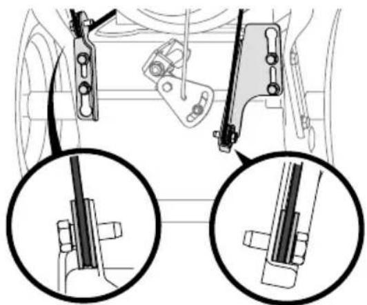
- Secure chute control head to chute support bracket with clevis pin (c) and cotter pin (d) removed in Step 1 (Figure 14).
text_image
Technical diagram of a vehicle seat assembly with labeled parts (c, d) and a magnified inset showing the mechanical component.Figure 14
- Finish securing chute control head to chute support bracket with wing nut (or locknut if equipped) (a) and hex screw (b) removed in Step 1 (Figure 15).
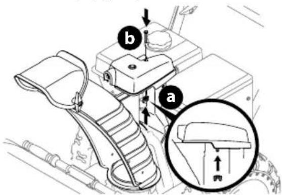
text_image
Technical diagram of a vehicle seatbelt mechanism with labeled parts and an inset showing a bracket detail view.Figure 15
- Insert chute control rod into the support bracket on rear of the dash panel (Figure 16).

natural_image
Technical line drawing of a mechanical device with lever and handle (no text or symbols)Figure 16
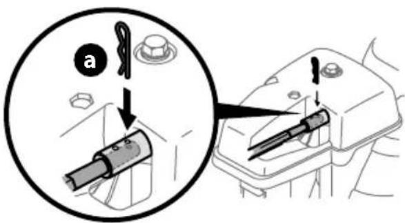
- Remove hairpin clip (a) from rear of chute control head (Figure 17).
text_image
Diagram showing mechanical assembly with labeled parts (a) and (b), including a magnified inset view of a tool interacting with a component.Figure 17
- Insert chute control rod (b) into rear of chute control head (Figure 17) and secure with hairpin clip (a) removed in Step 5.
STOP
Continue to Set-Up (page 14).
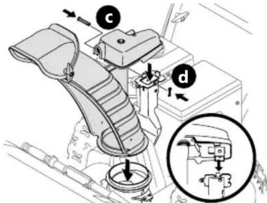
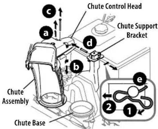
OVERHEAD CHUTE ROTATION CONTROL W/2-WAY PITCH OR 4-WAY PITCH & ROTATION CONTROL
text_image
Chute Assembly Chute Control Rod 2 Way/4 Way ControlFigure 18
NOTE: If equipped with a metal chute assembly - This assembly will install the same as the standard chute shown in the figures of this procedure.

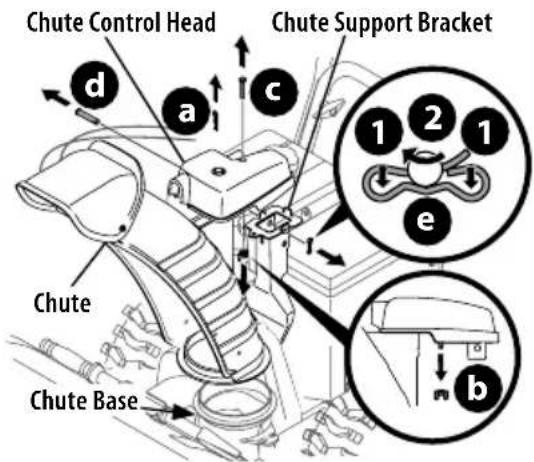
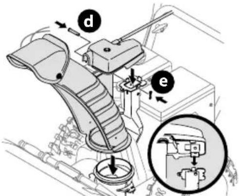
- Remove hairpin clip (a), wing nut (or locknut if equipped) (b) and hex screw (c) from chute control head and clevis pin (d) and bow-tie cotter pin (e) from chute support bracket (Figure 19).
text_image
Chute Control Head Chute Support Bracket Chute Assembly Chute Base e 1 2 c d bFigure 19
NOTE: For smoothest operation, cables should all be to the left of the chute control rod.
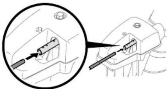
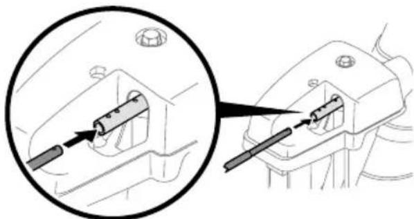
- Insert chute control rod into chute control head. Push rod as far into chute control head as possible, keeping holes in rod pointing upward (Figure 20).
natural_image
Technical diagram showing a mechanical component with a magnified inset view of its internal structure (no text or symbols)Figure 20
- Place chute assembly onto chute base and ensure chute control rod is positioned above lower handle. Install hex screw (c) removed in Step 1, but do not secure with wing nut (or locknut if equipped) at this time (Figure 21).
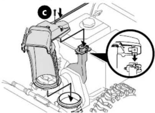
text_image
Technical diagram of a mechanical assembly with labeled components and a magnified inset showing internal components.Figure 21
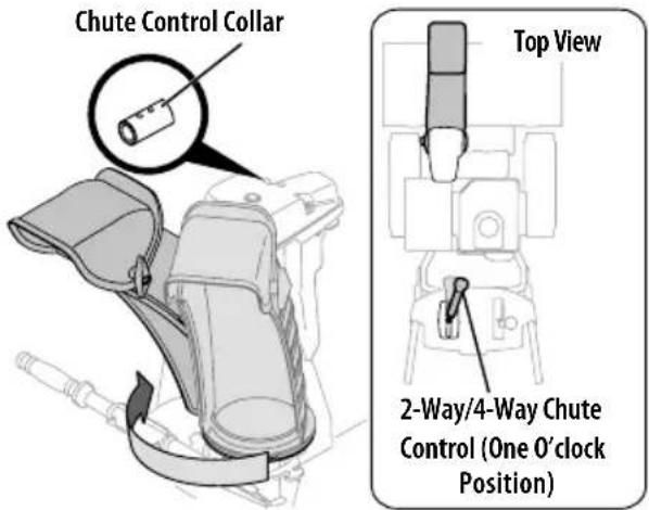
- Squeeze trigger on 2-way/4-way chute control and rotate chute by hand to face forward. The holes in chute control collar will be facing up (Figure 22).
text_image
Chute Control Collar Top View 2-Way/4-Way Chute Control (One O'clock Position)Figure 22
IMPORTANT: Chute will not rotate without squeezing trigger on 2-way/4-way chute control.
- Rotate 2-way/4-way chute control to one o'clock position (Figure 22) so that indicator arrow on pinion gear below control handle faces upward (Figure 23).
text_image
Diagram showing car interior with steering wheel and gear shift, highlighting mechanical component movementFigure 23
- Insert chute control rod into pinion gear under handle panel. Make sure to line up hole in rod with arrow on pinion gear (Figure 24).
text_image
Diagram showing a car interior with a highlighted section and directional arrow, likely illustrating vehicle or mechanical components.Figure 24
NOTE: Chute control rod will fit snug into pinion gear. Support rear of handle panel with one hand while inserting rod with your other hand to ensure rod is inserted all the way into pinion gear.
NOTE: The hole in the chute control rod is a reference for aligning rod with indicator arrow on pinion gear, and will be visible after rod has been fully inserted.
- Push chute control rod toward control panel until hole in rod lines up with hole in chute control input collar closest to chute control head and insert hairpin clip (a) removed in Step 1 (Figure 25).
text_image
Diagram showing a tool being inserted into a device, with labeled parts and directional arrows indicating action.Figure 25
NOTE: Second hole is used to achieve further engagement of chute control rod into pinion gear, if required. Refer to Product Care section for Chute Control Rod adjustments.
- Finish securing chute control head to chute support bracket with wing nut (b), clevis pin (d), and bow-tie cotter pin (e) removed in Step 1.
STOP
Continue to Set-Up (page 14).
OVERHEAD CHUTE CONTROL (FLEX SHAFT) W/STEEL CHUTE & 2-WAY PITCH CONTROL
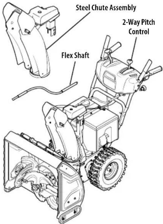
text_image
Steel Chute Assembly 2-Way Pitch Control Flex ShaftFigure 26
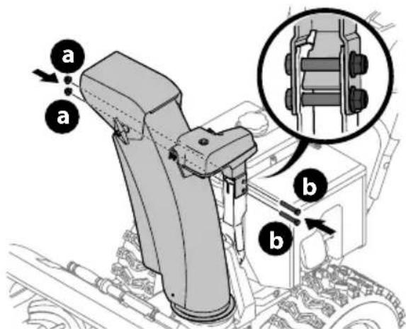
- Remove lock nuts (a) and hex screws (b) from chute support bracket (this will require two wrenches) (Figure 27).
text_image
Chute Control Head Steel Chute Assembly Chute Base Chute Support BracketFigure 27
- Place steel chute assembly onto chute base and chute control head onto chute support bracket (Figure 27).
- Secure chute control head to chute support bracket with lock nuts (a) and hex screws (b) removed in Step 1 (Figure 28).
text_image
Technical diagram of a mechanical assembly with labeled parts (a, b) and an inset showing a close-up of a component.Figure 28
NOTE: For smoothest operation, cables should all be to the left of the chute control rod.
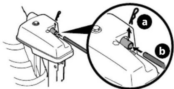
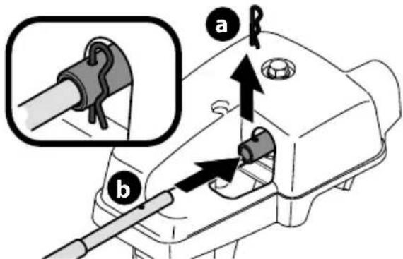
- Remove hairpin clip (a) from rear of chute control head (Figure 29).
text_image
Technical diagram showing mechanical assembly with labeled parts (a and b) and an inset view of a pipe fitting component.Figure 29
- Insert flex shaft (b) into rear of chute control head and secure with hairpin clip (a) removed in Step 4 (Figure 29).
SET-UP
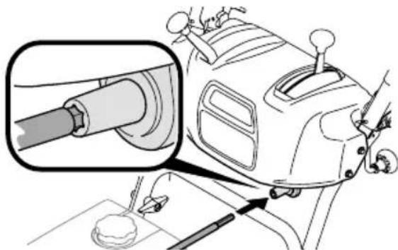
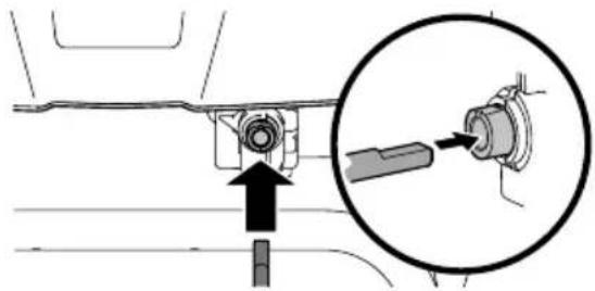
- Perform one of the following to connect the flex shaft to the chute control rod coupling:
- Models with Overhead Rotational - Insert hex end of flex shaft into chute control rod coupling under handle panel (Figure 30).
natural_image
Technical diagram of a vehicle's intake manifold with a magnified inset showing the shaft and wheel (no text or labels)Figure 30
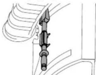
- Models with Electric Chute Control - Insert other end of flex shaft into chute control rod coupling under handle panel. Make sure to line up flat end of rod and flat end of coupler. You may need to rotate rod around until these two surfaces line up (Figure 31 inset).
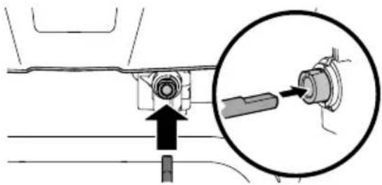
natural_image
Mechanical assembly diagram showing a bolt and shaft assembly with an inset close-up of the component (no text or symbols)Figure 31
Shift Rod (if Equipped)
- Ensure speed selector is in fastest forward speed.
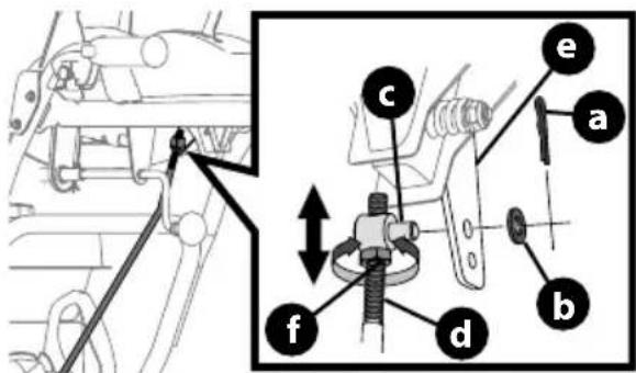
- Remove cotter pin (a) and washer (b) from adjustment ferrule (c) on shift rod (d) and pull it out from shift lever (e) (Figure 32 inset).
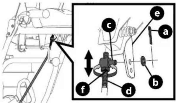
text_image
Technical diagram showing mechanical assembly with labeled parts (a, b, c, d, e, f) and directional arrows indicating movement or force.Figure 32
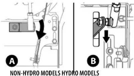
- Make sure the shift lever on the back of the transmission is rotated downward to the full extent of its rotation see Figure 33, Detail "A" for models without hydro transmission or Detail "B" for models with hydro transmission.
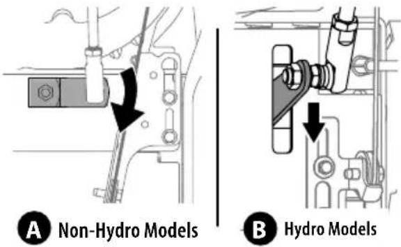
text_image
A Non-Hydro Models B Hydro ModelsFigure 33
- If necessary, loosen the jam nut (f) and rotate the ferrule up or down on the shift rod until the ferrule aligns with the upper hole in the shift lever (Figure 32). Tighten jam nut.
- Insert ferrule into top hole of shift lever and secure with cotter pin (a) and washer (b) removed in Step 2.
STOP
Continue to Set-Up (page 14).
OVERHEAD CHUTE ROTATION CONTROL W/4-WAY ELECTRIC PITCH & ROTATION CONTROL
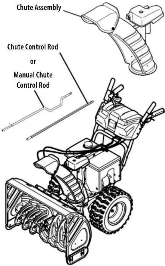
text_image
Chute Assembly Chute Control Rod or Manual Chute Control RodFigure 34
NOTE: If equipped with a metal chute assembly - This assembly will install the same as the standard chute shown in the figures of this procedure.
- Remove cotter pin (a), wing nut (b) and hex screw (c) from chute control head. Remove clevis pin (d) and bow-tie cotter pin (e) from chute support bracket (Figure 35).
text_image
Chute Control Head Chute Support Bracket d a c 1 2 1 e b Chute Chute BaseFigure 35
NOTE: For smoothest operation, cables should all be to the left of the chute control rod.
2. Insert round end of chute control rod into chute control head. Push rod as far into chute control head as possible, keeping holes in rod pointing upward (Figure 36).
natural_image
Technical diagram showing a mechanical component with a magnified inset view of its internal structure (no text or symbols)Figure 36
- Place chute onto chute base and ensure chute control rod is positioned above lower handle. Secure chute control head to chute support bracket with clevis pin (d) and bow-tie cotter pin (e) removed in Step 1 (Figure 37).
text_image
Technical diagram of a mechanical assembly with labeled parts (d, e) and an inset showing a close-up of a component.Figure 37
- Finish securing chute control head by installing hex screw (c) and wing nut (b) removed in Step 1 (Figure 38).
text_image
Technical diagram of a vehicle's intake mechanism with labeled parts (c) and zoomed-in detail view (b)Figure 38
- Insert other end of chute control rod into coupler below handle panel. Make sure to line up flat end of rod and flat end of coupler. You may need to rotate rod around until these two surfaces line up (Figure 39 inset).
natural_image
Mechanical assembly diagram showing a component being inserted into a housing, with an inset close-up highlighting the insertion area (no text or symbols present)Figure 39
- Push chute control rod toward the control panel until hole in rod lines up with middle hole in chute control coupler and insert cotter pin (a) removed in Step 1 (Figure 40).

text_image
Technical diagram showing mechanical assembly steps with labeled component 'a' and directional arrows indicating movementFigure 40
NOTE: There is a reference hole provided at rear end of control rod to help know when holes are vertical.
NOTE: Hole furthest from chute control head is used to achieve further engagement of chute control rod into coupler under control panel, if required. Refer to Adjustments, Overhead Chute Control on page 16.
NOTE: For models equipped with manual chute control rods, the hole closest to chute control head is used for manual movement of chute assembly, if required. Refer to Operation, Manual Chute Rotation Control & Electric Chute Control on page 23.
STOP
Continue to Set-Up (page 14).
SET-UP
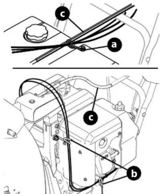
Chute Control Cable Routing (If Equipped)
For models equipped with 2-way or 4-way chute controls, electric chute control and/or chute-pitch controls, ensure control cables are routed properly.
Chute control cables are routed through a single wire guide (a) on top of the engine and/or through two wire guides (b) located on the front and left side of the engine (Figure 41).
NOTE: On models equipped with a cable tie securing the cables to the rear of the gas tank, pull the cables toward the chute and pull the cable tie snug to secure the cables in place.
NOTE: For smoothest operation, cables should all be to the left of the chute control rod (c).
NOTE: The number of cables routed through the wire guides will vary depending on model.
-
Locate cable guide(s) and perform the following:
-
Top Mounted Wire Guide (a) - Check that all cables are properly routed through cable guide on top of engine (Figure 41).
- Front and Side Mounted Wire Guides (b) - Check that all cables are properly routed through the wire guide below the left side of the engine and the wire guide below the chute control head (Figure 41).
text_image
Technical diagram showing mechanical assembly with labeled parts (a, b, c) and connection linesFigure 41
Shear Pins Storage (If Equipped)
On select models, holes are provided in the rear of the handle panel for shear pin (a) and bow-tie cotter pin (b) storage as shown in Figure 42. If not provided, make sure to store them in a safe place until needed.
text_image
Technical diagram showing three labeled mechanical components with bolted fasteners and adjustment arrowsFigure 42
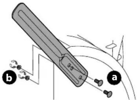
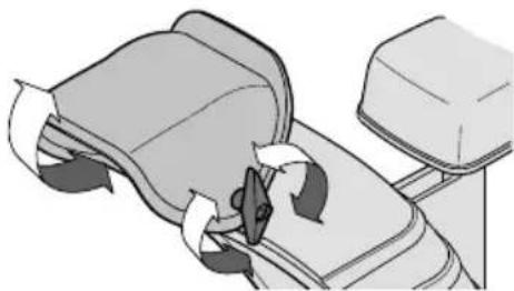
Drift Cutters (If Equipped)
The drift cutters are mounted inverted at the factory for shipping purposes.
Non-Adjustable
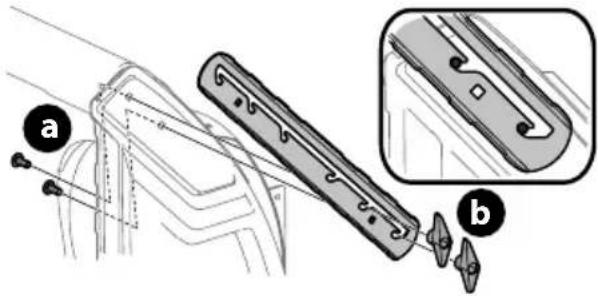
- Remove two carriage bolts (a) and lock nuts (b) that secure each drift cutter, and remove them from the sides of auger housing (Figure 43).
text_image
Diagram illustrating a mechanical device with labeled parts (a and b) and directional arrows indicating motion or force.Figure 43
- Turn the drift cutters around and position them as shown in Figure 43 to the outside of the auger housing.
- Attach drift cutters with carriage bolts (a) and lock nuts (b) removed in Step 1.
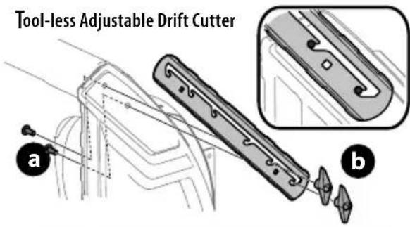
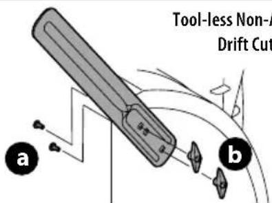
Tool-less
- Remove two carriage bolts (a) and wing nuts (b) that secure each drift cutter, and remove them from the sides of auger housing (Figure 44).
text_image
Tool-less Adjustable Drift Cutter a bTool-less Non-Adjustable Drift Cutter
text_image
Tool-less Non-A Drift Cut a bFigure 44
- Turn the drift cutters around and position them as shown in Figure 44 to the outside of the auger housing.
- Attach drift cutters with carriage bolts (a) and wing nuts (b) removed in Step 1.
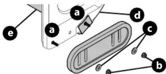
Skid Shoes (If Applicable)
Select models require the installation to the provided skid shoes.
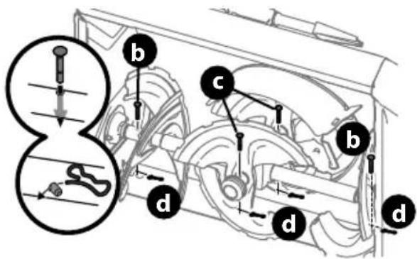
- Using the two carriage bolts (a) and hex flange nuts (b) and flat washers (if equipped) (c), secure the skid shoes to the auger housing (d). Hand tighten hex flange nuts (Figure 45).
- Adjust the skid shoes to provide a minimum of 1/8th inch clearance between the shave plate (e) and the ground. Securely tighten hex flange nuts.
- If necessary refer to Skid Shoes in the Adjustments section on page 15.
text_image
a a d c bFigure 45
Chute Clean-Out Tool
The chute clean-out tool is fastened to the top of the auger housing with a mounting clip (Figure 46).
natural_image
Technical line drawing of a mechanical component with threaded fastener and shaft (no text or symbols)Figure 46
Tire Pressure (If Applicable)
NOTE: Not applicable to models equipped with airless tires.

WARNING
Under any circumstance do not exceed manufacturer's recommended psi. Equal tire pressure should be maintained at all times. Excessive pressure when seating beads may cause tire/rim assembly to burst with force sufficient to cause serious injury. Refer to sidewall of tire for recommended pressure.
The tires are over-inflated for shipping purposes. Check tire pressure before operating. Refer to tire side wall for tire manufacturer's recommended psi and adjust pressure, if necessary.
NOTE: Equal tire pressure is to be maintained at all times for performance purposes.
Adjustments
Skid Shoes
Snow blower skid shoes are adjusted at a factory setting roughly 1/8" below the shave plate. Adjust them upward or downward, if desired, prior to operating.

WARNING
Use extreme caution when operating on or near gravel and adjust skid shoes to clear gravel or crushed rock surfaces to avoid picking up and throwing objects which could cause serious injury or property damage.
- For close snow removal on a smooth surface, raise skid shoes higher on auger housing.
- Use a lower position when area to be cleared is uneven, such as a gravel driveway.
IMPORTANT: If you choose to operate on a gravel surface, keep skid shoes in position for maximum clearance between ground and shave plate.
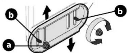
- Loosen four hex nuts (a) (two on each side) and carriage bolts (b). Move skid shoes to desired position (Figure 47).
text_image
a b bFigure 47
NOTE: The skid shoes on your snow blower may look slightly different (and have different hardware) than ones shown in Figure 47.
- Make certain entire bottom surface of skid shoe is against ground to avoid uneven wear on skid shoes.
- Securely tighten hex nuts (a) to carriage bolts (b).
Adjustable Drift Cutters (If Equipped)
The drift cutters are mounted inverted at the factory for shipping purposes.
- Loosen the two carriage bolts (a) and wing nuts (b) that secure each drift cutter to the sides of auger housing (Figure 48).
text_image
Technical diagram showing a mechanical component with labeled parts (a) and (b), including a detailed inset view.Figure 48
- Slide the drift cutters to desired height.
- Securely tighten the two carriage bolts and wing nuts that secure each drift cutter to the sides of auger housing.
Manual Chute pitch Adjustment (If Equipped)
NOTE: For models without manual chute pitch, see Operation on page 21-22.
On models with manual chute pitch, the distance snow is thrown can be adjusted by changing angle of chute assembly. To do so:
- Loosen wing nut found on left side of the upper chute assembly (Figure 49).
natural_image
Illustration of a hand pressing down on a mechanical component with directional arrows (no text or symbols)Figure 49
- Pivot chute upward or downward before re-tightening wing nut.
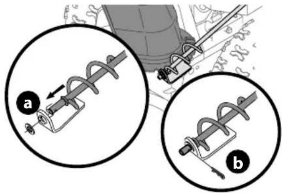
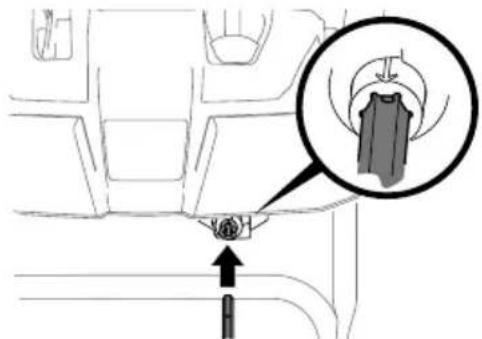
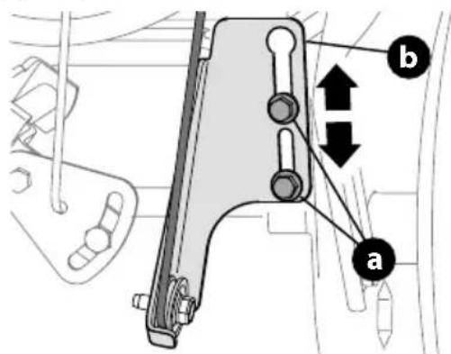
Side Chute Control (If Equipped)
If spiral at bottom of the chute control rod is not fully engaging with chute assembly, the bracket needs to be adjusted. To do so:
- Loosen two nuts (a) which secure the bracket and reposition it slightly (Figure 50).
- Re-tighten nuts.
natural_image
Mechanical diagram showing a spring-loaded cable and its internal components (no text or symbols)Figure 50
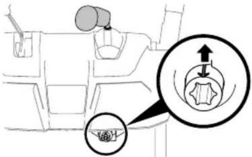
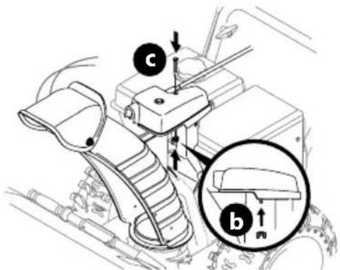
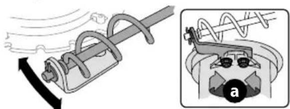
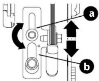
Overhead Chute Control (If Equipped)
If chute fails to remain stationary during operation, preload of chute can be adjusted by tightening hex nut found on front of chute control head.
- To increase preload, tighten hex nut (a) clockwise in 14 turn intervals. The chute control rod (b) will need to be held stationary when tightening the nut (Figure 51).
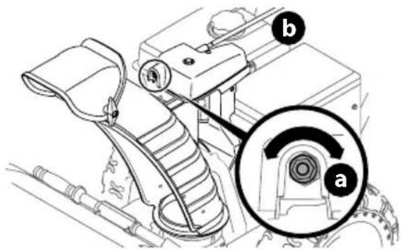
text_image
Technical diagram of a mechanical assembly with labeled parts (a and b) and an inset circular detail view showing internal components.Figure 51
- If chute control rod is difficult to turn, decrease preload by loosening hex nut counter-clockwise in 14 turn intervals.
2-Way or 4-Way Chute Control (If Equipped)
To adjust chute control rod for increased engagement into the handle panel control, proceed as follows:
- Remove hairpin clip (a) from hole closest to chute assembly on chute control head.
- Pull out chute control rod until hole in it lines up with second hole in chute control head (Figure 52).
text_image
Diagram showing a mechanical device being inserted into a housing, with labeled parts and directional arrows indicating insertion or disassembly.Figure 52
- Reinsert hairpin clip (a) through this hole and chute control rod.
Adjustable Shave Plate (If Equipped)
- Allow engine to run until it is out of fuel. Do not attempt to drain fuel from the engine. Remove safety key or disconnect spark plug wire.
- Carefully pivot snow blower up and forward so that it rests on front of auger housing.
- Loosen rear skid shoe nuts (a) on both sides of auger housing and remove carriage bolts (b) and hex nuts (c) which attach shave plate (d) to the bottom of the auger housing (Figure 53).
text_image
a b c d b c c a b cFigure 53
NOTE: 3-Stage model shown.
- Adjust the shave plate to one of 2 mounting positions. Reinstall and securely tighten all carriage bolts, nuts and skid shoe hardware from Step 3 (Figure 53).
- Readjust the skid shoes. See Skid Shoes on page 15.
Auger Control
WARNING
Prior to operating, carefully read and follow all instructions below. Perform all adjustments to verify your snow blower is operating safely and properly.
Refer to the Operation section on page 20 for the location of auger control lever and check adjustment as follows:
- When auger control lever is released and in disengaged "UP" position, the cable should have very little slack. It should NOT be tight.
- In a well-ventilated area, start the engine. Refer to your Engine Operator's Manual.
- While standing in the operator's position (behind the handles), depress the auger control lever to engage auger.
- Allow auger to remain engaged for approximately ten (10) seconds before releasing auger control lever. Repeat this several times.
- With auger control lever in disengaged "UP" position, walk to front of machine.
- Confirm that auger has completely stopped rotating and shows NO signs of motion. If auger shows ANY signs of rotating, immediately shut OFF engine, remove safety key or disconnect spark plug wire. Wait for ALL moving parts to stop before readjusting auger control lever.
- Loosen the two hex screws (a) on auger control cable bracket (b) (Figure 54).
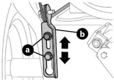
text_image
a bFigure 54
- Position auger control bracket (b) upward to provide more slack in cable or downward to increase tension (Figure 54).
- Re-tighten the hex screws (a).
- Repeat the steps 1 - 6 to verify proper adjustment has been achieved.
Shift Cable (If Equipped)
If full range of speeds (forward and reverse) cannot be achieved, adjust shift cable as follows:
- Place shift lever in fastest forward speed position.
- Loosen hex nut (a) on shift cable index bracket (b) (Figure 55).
- Pivot bracket downward to take up slack in cable.
- Re-tighten hex nut. Torque to 100-120 in-lbs (11.3-13 Nm).
- If further adjustment is necessary move the shift cable to one of the alternate holes in the shift cable index bracket.
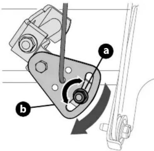
text_image
Technical diagram of a mechanical clamp mechanism with labeled parts a and b, showing rotational motion direction.Figure 55
Shift Rod (If Equipped)
If full range of speeds (forward and reverse) cannot be achieved, adjust shift rod as follows:
- Place shift lever in fastest forward speed position.
- Remove cotter pin (a) and washer (b) from adjustment ferrule (c) on shift rod (d) and pull it out from shift lever (e) (Figure 56).
text_image
Technical diagram showing mechanical assembly with labeled parts (a, b, c, d, e, f) and directional arrows indicating movement or force.Figure 56
- Make sure the shift lever on the back of the transmission is rotated downward to the full extent of its rotation. See Figure 57, Detail "A" for models without hydro transmission or Detail "B" for models with hydro transmission.
text_image
A NON-HYDRO MODELS HYDRO MODELS BFigure 57
- If necessary, loosen the jam nut (f) and rotate the ferrule up or down on the shift rod until the ferrule aligns with the upper hole in the shift lever (Figure 56). Tighten jam nut.
- Insert the ferrule into the upper hole and secure with the washer and cotter pin.
Drive Control (NON-Hydro Models) (If Equipped)
When drive control lever is released and in disengaged "UP" position, cable should have very little slack. It should NOT be tight.
NOTE: If excessive slack is present in drive cable or if drive is disengaging intermittently during operation, the cable may be in need of adjustment.
Check adjustment of drive control lever as follows:
- With drive control lever released, push snow blower gently forward. It should roll freely.
- Engage drive control lever and gently attempt to push the snow blower forward. The wheels should not rotate or roll freely.
- If equipped with a shift lever, with drive control lever released, move shift lever back and forth between the R2 position and the F6 position several times. There should be no resistance in the shift lever.
NOTE: If any of the above tests fail, the drive cable is in need of adjustment. Proceed as follows:
-
Shut OFF engine, remove safety key or disconnect spark plug wire. Refer to the Engine Operator's Manual.
-
Loosen the two hex screws (a) on drive cable bracket (b) (Figure 58).
text_image
Technical diagram showing mechanical assembly with labeled parts a and b, including directional arrows indicating movement or force.Figure 58
- Position drive cable bracket upward to provide more slack (or downward to increase cable tension).
- Re-tighten the hex screws.
- Check adjustment of drive control lever as described above to verify proper adjustment has been achieved.
Drive Control (Hydro Models) (If Equipped)
When drive control lever is released and in disengaged "UP" position, cable should have very little slack. It should NOT be tight.
NOTE: If excessive slack is present in drive cable or if drive is disengaging intermittently during operation, the cable may be in need of adjustment.
- Shut OFF engine, remove safety key or disconnect spark plug wire. Refer to the Engine Operator's Manual.
- Loosen upper hex screw (a) on drive cable bracket (b) (Figure 59).
text_image
Technical diagram showing mechanical assembly with labeled parts a and b, including directional arrows and circular motion indicators.Figure 59
- Position bracket upward to provide more slack (or downward to increase cable tension).
- Re-tighten upper hex screw.
- Check for excessive slack in drive control cable. If necessary repeat Steps 2-4 to re-adjust the drive control.
Snowblower Equipped with Cordless Battery Start
NOTE: To ensure maximum performance and life of lithium-ion battery packs, charge the battery fully before first use.
WARNING
The battery contains corrosive fluid and toxic material; handle with care and keep away from children. Do not puncture, disassemble, mutilate or incinerate the battery. Explosive gases could be vented during charging or discharging. Use in a well ventilated area, away from sources of ignition.
WARNING
Read all safety warnings, instructions, and cautionary markings for the battery pack, charger and product. Failure to follow the warnings and instructions may result in electric shock, fire and/or serious injury.
IMPORTANT: Refer to instructional manual supplied with battery charger for charging, maintenance and battery disposal instructions.
NOTE: Do not use if battery or battery adapter is damaged. Contact Customer Support for assistance and for the name of your nearest servicing dealer.
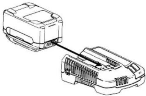
CHARGING THE BATTERY PACK (IF EQUIPPED)
IMPORTANT: Refer to instructional manual supplied with battery charger for charging, maintenance and battery disposal instructions.
natural_image
Line drawing of two electronic devices connected by a cable, showing internal components (no text or symbols)Figure 60
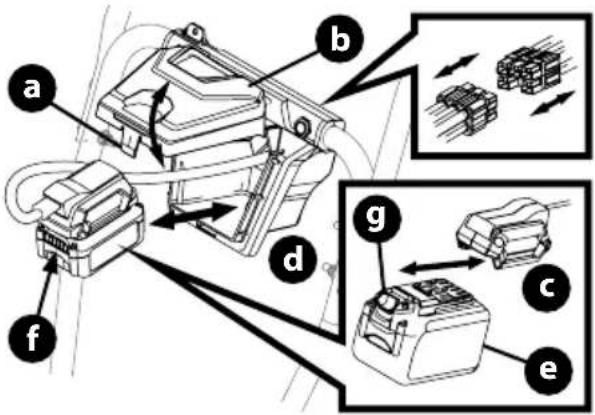
INSTALLING/REMOVING THE BATTERY PACK
- Installing the battery pack (Figure 61):
a. Push up on finger tab (a) and lift the battery box cover (b). b. Remove the battery adapter (c) from the battery box (d).
NOTE: If necessary the battery adapter can be disconnected from the battery start wiring harness (Insert, Figure 61).
c. Insert the battery pack (e) into the battery adapter. An audible "click" will be heard when the battery is properly connected. d. Place the battery pack and battery adapter into the battery box so that the battery gauge button and battery gauge (f) are facing the front of the snowblower.
NOTE: Ensure bottom of battery pack completely sits flat on the battery box floor.
e. Close the battery box cover. There will be an audible "click" when the battery box cover is closed and latched.
- Removing the battery pack (Figure 61):
a. Push up on finger tab and lift the battery box cover (a).
b. Remove the battery adapter (b) and battery pack (d) from the battery box. (c)
c. Press the battery pack release button (g) and remove the battery pack from the battery adapter.
text_image
Technical diagram of a mechanical assembly with labeled components (a–f) and zoomed-in insets showing internal components.Figure 61
ADDING FUEL & OIL
Refer to the Engine Operator's Manual for information on adding fuel and oil.
MODEL FEATURES
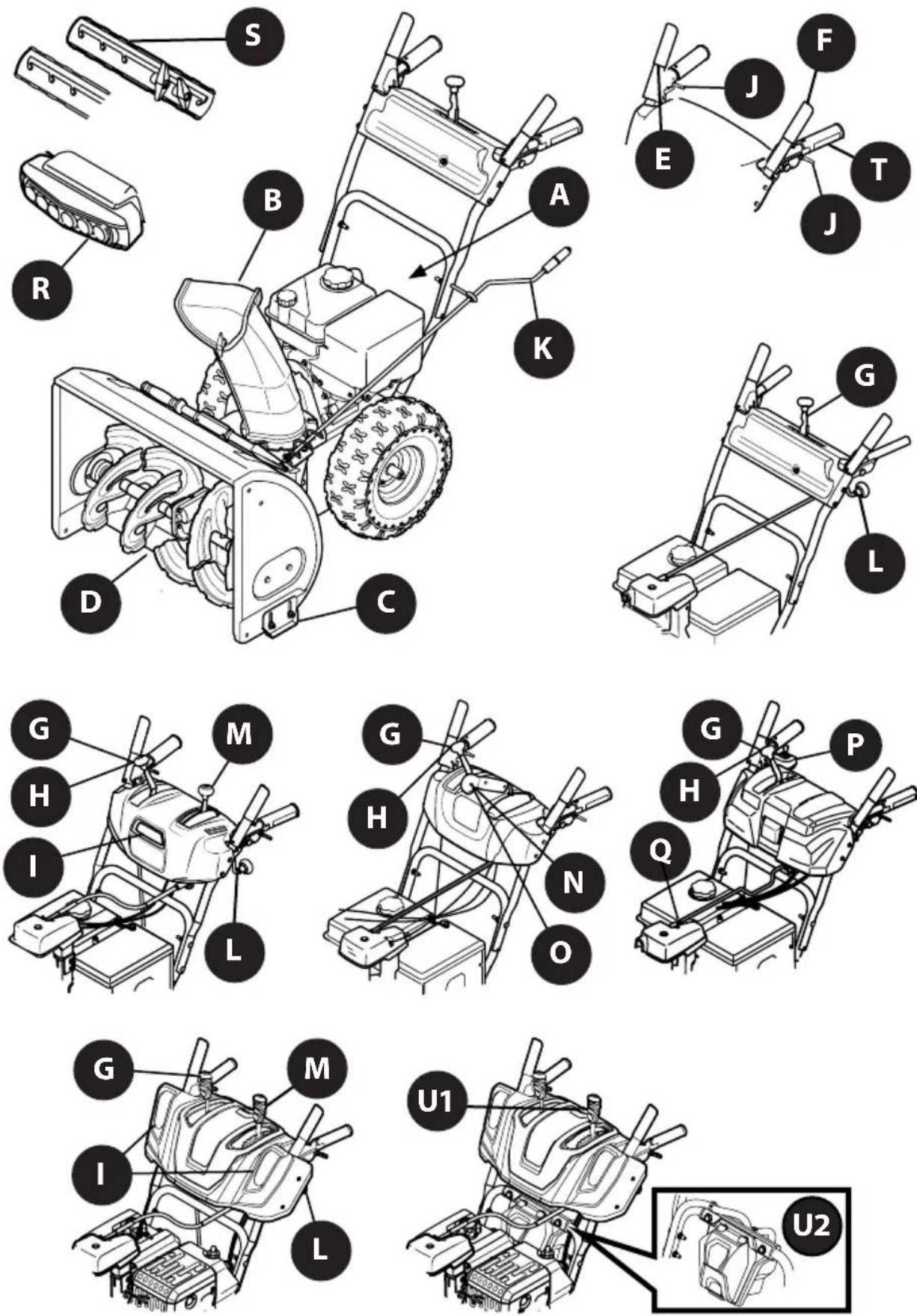
Figure 62
OPERATION
Features
Snow blower controls and features are described below and may be illustrated in Figure 62.
NOTE: This Operator's Manual covers several models. Snow blower features may vary by model. Not all features in this manual are applicable to all snow blower models and the snow blower depicted may differ from yours.
NOTE: All references to the left or right side of the snow blower are from the operator's position. Any exceptions will be noted.
A. ENGINE CONTROLS
Refer to your Engine Operator's Manual for location and description of engine controls pertaining to your engine.
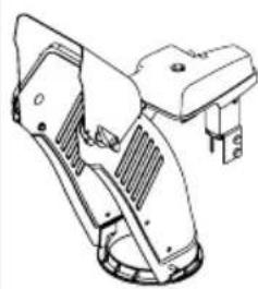
B. CHUTE ASSEMBLY
Snow gathered into the auger and impeller housings is discharged out the chute assembly.
C. SKID SHOES
Skid shoes provide the proper clearance of the shave plate for the surface conditions and the snow to be cleared. Adjust upward for hard-packed snow. Adjust downward when operating on gravel or crushed rock surfaces. Refer to Skid Shoes on page 15.
D. AUGERS
When engaged, the augers rotate and gather snow into the auger and impeller housings.
The drive control lever is located on the right handle. Squeeze the control lever down against the handle to engage the wheel drive. Release to stop (Figure 63).
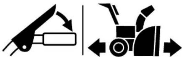
natural_image
Two black-and-white diagrams showing a tool and a tractor, with directional arrows indicating movement or force (no text or symbols)Figure 63
NOTE: Always release drive control lever before changing speeds on all models except the hydro transmission models. Failure to do so will result in increased wear on your machine's drive system.
*On select models, the drive control lever also locks the auger control lever so that you can operate the chute control without interrupting the snow blowing process. When both the auger and drive levers are engaged at any time, the operator can release the auger control lever (on the left handle) and the augers will remain engaged. Release both control levers to stop augers and wheel drive.
The auger control lever down is located on the left handle. Squeeze the control lever against the handle to engage the augers and start snow blowing action. Release to stop (Figure 64).
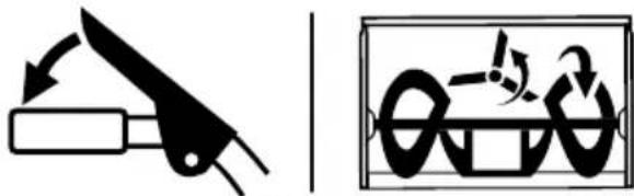
natural_image
Two black-and-white diagrams showing a knife and a mechanical device with arrows indicating motion (no text or symbols)Figure 64
IMPORTANT: Refer to the Auger Control information in the Assembly & Set-Up section prior to operating your snow blower. Read and follow all instructions carefully and perform all adjustments to verify your snow blower is operating safely and properly.
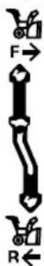
G. SHIFT LEVER (6-SPEED TRANSMISSION) (IF EQUIPPED)
The shift lever is located on the handle panel and is used to determine ground speed and direction of travel.
- Forward
There are six forward (F) speeds. Position one (1) is the slowest and position six (6) is the fastest.
- Reverse
There are two reverse (R) speeds. Position one (1) is the slowest and position two (2) is the fastest.
H. SHIFT LEVER (HYDRO TRANSMISSION) (IF EQUIPPED)
The shift lever is located on the handle panel and is used to determine ground speed and direction of travel. The further forward the lever is moved the faster it will travel. Moving past the detent position to the reverse direction will move the snow blower in reverse.
I. HEADLIGHT (SINGLE OR DUAL) (IF EQUIPPED)
The headlight(s) located on the front of the handle panel is/are automatically turned ON when the engine is started.
OPERATION
J. STEERING TRIGGER CONTROLS (IF EQUIPPED)
The left and right wheel steering trigger controls are located on the underside of the handles (Figure 65).
IMPORTANT: Models with Hydro Transmission - When moving the snow blower without starting the engine, squeeze both right and left triggers to disengage the drive.
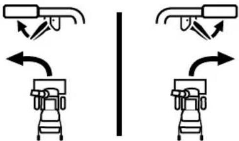
natural_image
Diagram showing two identical mechanical or robotic device configurations with bidirectional arrows indicating motion (no text or symbols)Figure 65
- Squeeze the right trigger control to turn right.
- Squeeze the left trigger control to turn left.

CAUTION
Operate the snow blower in open areas until you are familiar with these controls.
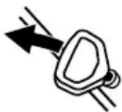
K. SIDE MOUNTED CHUTE ROTATION CONTROL (IF EQUIPPED)
The side mounted chute rotation control is located on the left side of the snow blower. To change direction in which snow is thrown, rotate the control (Figure 66).
natural_image
Two diagrams showing a mechanical device with rotational motion and a magnified view of a circular component (no text or symbols)Figure 66
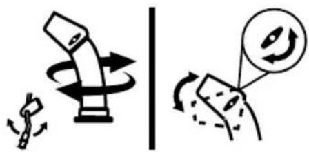
L. OVERHEAD CHUTE ROTATION CONTROL (IF EQUIPPED)
The overhead chute rotation control is located at the rear of the snow blower under the handle panel.
• To change the direction in which snow is thrown, rotate the control (Figure 67).
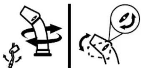
natural_image
Two diagrams showing a pencil and a magnifying glass with rotating arrows, no text or symbols present.Figure 67
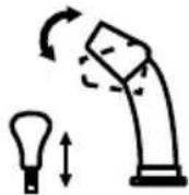
M. CHUTE-PITCH CONTROL (IF EQUIPPED)
The two-way chute-pitch control is located on the left side of the dash panel and is used to raise and lower the upper chute, which will change the distance the snow is thrown.
To raise or lower the upper chute, move the lever forward or backward (Figure 68).
Two-Way Chute-Pitch Control
- To Reduce the Distance Snow is Thrown: Move the lever forward to tilt the upper chute down (Figure 68).
- To Increase the Distance Snow is Thrown: Move the lever rearward to tilt the upper chute up (Figure 68).
Two-Way Indexed Chute-Pitch Control
- To Reduce the Distance Snow is Thrown: Disengage lever from the current chute setting. Move the lever forward to tilt the upper chute down to the desired setting (a) (Figure 68).
- To Increase the Distance Snow is Thrown: Disengage lever from the current chute setting. Move the lever rearward to tilt the upper chute down to the desired setting (b) (Figure 68).
TWO-WAY CHUTE-PITCH CONTROL
TWO-WAY INDEXED CHUTE-PITCH CONTROL
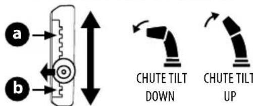
text_image
a b CHUTE TILT DOWN CHUTE TILT UPFigure 68
N. 2-WAY CHUTE ROTATION CONTROL (IF EQUIPPED)
The 2-Way chute rotation control is located on the left side of the dash panel.
- To change direction in which snow is thrown, squeeze button on control and rotate to the right or to the left (Figure 69).
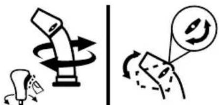
text_image
Diagram illustrating a mechanical or electrical operation with rotating components and directional arrows, possibly indicating motion or rotation.Figure 69
OPERATION
0. 4-WAY CHUTE ROTATION CONTROL (IF EQUIPPED)
The 4-Way chute rotation control is located on the left side of the dash panel.
- To change the direction in which snow is thrown, squeeze the button on the control and rotate to the right or to the left (Figure 70).
• To change the distance which snow is thrown, move the control forward or backward.
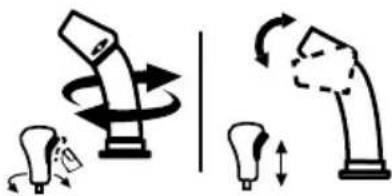
natural_image
Illustration of a robotic arm with rotating arms and motion arrows, no text or symbols presentFigure 70
P. ELECTRIC CHUTE PITCH & ROTATION CONTROL (JOYSTICK) (IF EQUIPPED)
The electric chute control is located on the right side of the dash panel (Figure 71).
- To change the direction in which snow is thrown, move the joystick to the right or to the left.
- To change the distance which snow is thrown, move the joystick forward or backward.
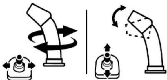
natural_image
Diagram showing two mechanical lever mechanisms with rotational motion arrows, no text or symbols presentFigure 71
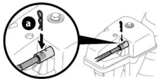
Q. MANUAL CHUTE ROTATION CONTROL & ELECTRIC CHUTE CONTROL (JOYSTICK) (IF EQUIPPED)
Follow this procedure to manually change the chute direction on models equipped with an electric chute control (joystick) and manual chute rotation control rod only (Figure 62).
- Remove cotter pin (a) from either of the holes furthest from the chute assembly on chute control head (Figure 72).
text_image
a aFigure 72
-
Push in chute control rod until the hole in it lines up with the third hole in chute control head (Figure 72).
-
Reinsert cotter pin (a) through this hole and chute control rod (Figure 72).
-
Grasp indented portion of chute control rod and manually rotate chute assembly to the right or to the left (Figure 73).
natural_image
Technical line drawing of a mechanical assembly with no visible text or symbolsFigure 73
R. LED LIGHT BAR (IF EQUIPPED)
The LED headlight is located on top of the auger housing and is automatically turned ON when the engine is running.
S. DRIFT CUTTERS (IF EQUIPPED)
The drift cutters are designed for use in deep snow. Their use is optional for normal snow conditions. Maneuver snow blower so that the cutters penetrate a high standing snow drift to assist snow falling into the augers.
T. HEATED GRIPS (IF EQUIPPED)

CAUTION
It is recommended that you wear gloves when using the heated grip. If the heated grips become too hot, turn them OFF.
To activate the heated grips, move switch found on top (a) or on the rear (b) of dash panel into the ON position (Figure 74). To turn OFF heated grips, move switch to the OFF position.
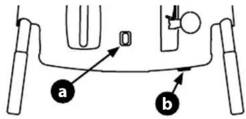
text_image
a b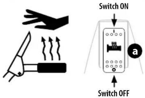
text_image
Switch ON Switch OFF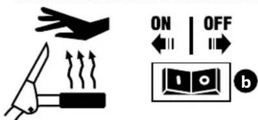
text_image
ON | OFF bFigure 74
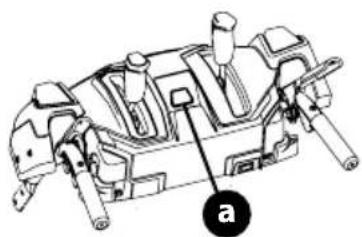
U. CORDLESS BATTERY START (IF EQUIPPED)
- Cordless Battery Start Button: The cordless battery start button (a) is located in the center of the handle panel. After adjusting the engine controls as necessary, pressing the cordless battery start button engages the engine's electric starter (Figure 75). Refer to the Engine Operator's Manual for more information on how to use the engine controls.
IMPORTANT: Do not press the cordless battery start button while the engine is running. The cordless battery start button is not a engine stop button.
natural_image
Technical line drawing of a mechanical assembly with labeled component 'a' (no text or symbols beyond label)Figure 75
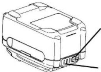
- Battery Box: The battery box is located on the handle if the snowblower is equipped with a cordless battery start.
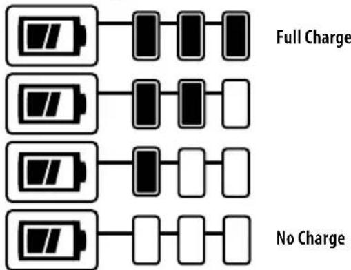
CHECKING BATTERY PACK CHARGE (IF EQUIPPED)

WARNING
Read all safety warnings, instructions, and cautionary markings for the battery pack, charger and product. Failure to follow the warnings and instructions may result in electric shock, fire and/or serious injury.
IMPORTANT: Refer to instructional manual supplied with battery charger for charging, maintenance and battery disposal instructions.
- Press the battery gauge button on front of the battery pack to check charge level (Figure 76):
- Charged Battery - One to three lights of the battery gauge will light to show charge level.
- Discharged Battery - If no lights show, charge battery pack. Refer to manual supplied with battery charger for charging instructions.
natural_image
Technical line drawing of a mechanical component with no visible text or symbolsBattery Gauge
Button
Battery Gauge
flowchart
graph TD
    A["Full Charge"] --> B["Black Battery"]
    B --> C["White Battery"]
    D["No Charge"] --> E["White Battery"]
    E --> F["Black Battery"]
    F --> G["White Battery"]
    H["No Charge"] --> I["White Battery"]
    I --> J["Black Battery"]
    J --> K["White Battery"]
Figure 76
STARTING AND STOPPING THE ENGINE

WARNING
Always keep hands and feet clear of moving parts. Do not use a pressurized starting fluid. Vapors are flammable.
Refer to the Engine Operator's Manual for instructions on starting and stopping the engine.


Electric Start
Recoil Start
Figure 77
TO ENGAGE DRIVE
- With the throttle control in the Fast (rabbit) position, move the shift lever into one of the six forward (F) positions or two reverse (R) positions on 6-speed models or in the desired position on the Hydro models. Select a speed appropriate for the snow conditions and a comfortable pace.
- Squeeze the drive control lever against the handle and the snow blower will move. Release to stop.
TO ENGAGE AUGERS
To engage the augers, squeeze the auger control lever against the left handle. Release to stop.
TO STEER (IF EQUIPPED)
With the drive control lever engaged, squeeze the right steering trigger control to turn right, or squeeze the left steering trigger control to turn left.

CAUTION
Operate the snow blower in open areas and at slow speeds until you are familiar with the drive control and comfortable operating the steering controls.
CLEARING A CLOGGED CHUTE ASSEMBLY

WARNING
Never use your hands to clear a clogged chute assembly. Shut OFF engine, remove safety key or disconnect spark plug wire and remain behind handles until all moving parts have stopped before unclogging.
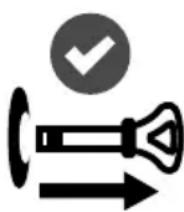
The chute clean-out tool is conveniently fastened to the rear of the auger housing with a mounting clip. Should snow and ice become lodged in the chute assembly during operation, proceed as follows to safely clear the chute assembly and chute opening:
- Release both the auger control lever and the drive control lever and rotate the chute assembly to the left.
- SHUT THE ENGINE OFF! Remove safety key or disconnect spark plug wire. Refer to the Engine Operator's Manual.
- Remove clean-out tool from the clip which secures it to the rear of the auger housing.
- Use the shovel-shaped end of the clean-out tool to dislodge and scoop any snow and ice which has formed in and near the chute assembly. Always use the clean-out tool (Part # 931-2643), not your hands. Refer to the separate supplement for clean-out tool ordering information, if lost or damaged (Figure 78).
- Re-fasten the clean-out tool to the mounting clip on the rear of the auger housing, reinsert the safety key or connect the spark plug wire and start the engine.
- While standing in the operator's position (behind the snow blower), engage the auger control lever for a few seconds to clear any remaining snow and ice from the chute assembly.
natural_image
Icon showing a stylized pen with an arrow and a checkmark inside a circle (no text or symbols)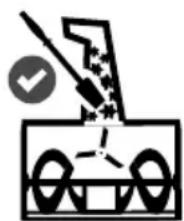
natural_image
Simple line drawing of a mechanical device with no text or symbols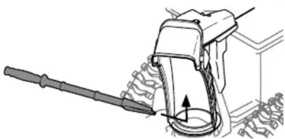
natural_image
Technical line drawing of a mechanical device with a tool and gear assembly (no text or symbols)Figure 78
REPLACING SHEAR PINS

CAUTION
NEVER replace the auger or central accelerator shear pins with anything other than OEM Part No. 738-04124A (round head replacement shear pins), 738-05273 (black colored, round head replacement shear pins) or 738-06654 (hex head replacement shear pins). Any damage to the auger gearbox or other components as a result of failing to do so will NOT be covered by your snow blower's warranty.

WARNING
Shut OFF engine, remove safety key or disconnect spark plug wire prior to replacing shear pins.
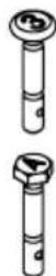
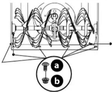
The augers are secured to the spiral shaft with shear pins (a, b or c) and cotter pins (d). If the auger should strike a foreign object or ice jam, the snow blower is designed so that the pins may shear. If the augers will not turn, check to see if the pins have sheared (Figure 79).
IMPORTANT: ALWAYS use the correct OEM replacement shear pin.
2-Stage Snow Blower replacement shear pins
- The auger is secured to the spiral shaft using round head shear pins (a) - OEM Part No. 738-04124A.
3-Stage Snow Blower replacement shear pins
- The side augers are secured to the spiral shaft using round head shear pins (marked with a "3" on the head) (b) - OEM part number 738-05273.
- The central accelerator augers are secured to the spiral shaft using hex head shear pins (marked with an "A" on the head) (c) - OEM part number 738-06654.
2-Stage Snow Blowers
text_image
Diagram illustrating chromosome structure with labeled parts a and d, showing internal organs and genetic elements3-Stage Snow Blowers
text_image
Technical diagram of a mechanical assembly with labeled parts (a, b, c, d) and an inset showing a tool interacting with a component.Figure 79

WARNING
Before servicing, repairing or inspecting the snow blower, disengage the auger control lever. Stop the engine, remove the safety key or disconnect spark plug wire to prevent unintended starting.
TROUBLESHOOTING
Engine
- Engine fails to start, runs erratic, skips (hesitates) or idles poorly. Refer to the Engine Operator's Manual.
- Refer to the Engine Operator's Manual for engine-related troubleshooting and service.
Excessive Vibration
- Loose or damaged parts.
- Stop engine immediately, remove safety key or disconnect spark plug wire. Check for possible damage. Tighten all nuts and bolts. Repair as needed. If the problem persists, contact an authorized service center.
Fails to Propel Itself
- Drive control cable in need of adjustment.
- Adjust drive control cable. Refer to Drive Control on page 18.
- Drive belt loose or damaged.
- Replace drive belt. Contact an authorized Service Center.
- Friction wheel worn.
- Replace friction wheel. Refer to Service section on page 30.
Fails to Discharge Snow
- Chute assembly clogged.
- Stop engine immediately, remove safety key or disconnect spark plug wire. See Engine Operator's Manual.
- Clean chute assembly and inside of auger housing with clean-out tool. Refer to Clearing a Clogged Chute Assembly on page 25.
- Foreign object lodged in auger.
- Stop engine immediately, remove safety key or disconnect spark plug wire. See Engine Operator's Manual.
- Remove object from auger with clean-out tool. Refer to Clearing a Clogged Chute Assembly on page 25.
- Auger control cable in need of adjustment.
• Refer to Auger Control on page 17.
- Auger belt loose or damaged.
• Refer to Auger Belt Replacement on page 29.
- Shear pin(s) sheared.
• Refer to Replacing Shear Pins on page 26.
Chute fails to easily rotate
- Chute assembled incorrectly.
- Disassemble chute control and reassemble as directed in the Set-up section.
Pushes Snow Instead of Blowing
- Low/slow ground speed in wet/slushy snow 1-3" in depth.
- Increase ground speed and always operate snow blower engine at FULL throttle. Refer to Clearing a Clogged Chute Assembly on page 25.
- Shear pin(s) sheared.
• Refer to Replacing Shear Pins on page 26.
Overhead Chute Control Does Not Stay Stationary While Blowing Snow
- Insufficient preload applied to chute control.
- Refer to on Overhead Chute Control (If Equipped) on page 16.
MAINTENANCE
NOTE: If equipped with cordless battery start, remove battery before performing maintenance. See Installing/Removing The Battery Pack on page 19.
Engine
Refer to Engine Operator's Manual.
Tire Pressure
Refer to Tire Pressure on page 15 for information regarding tire pressure.
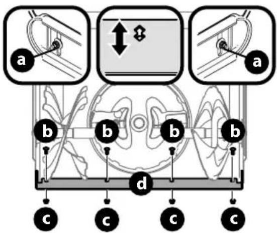
Shave Plate & Skid Shoes
The shave plate and skid shoes on the bottom of the snow blower are subject to wear. They should be checked periodically and replaced when necessary.
NOTE: Deluxe skid shoes (on select models) have two wear edges. When one side wears out, they can be rotated 180^ to use the other edge.
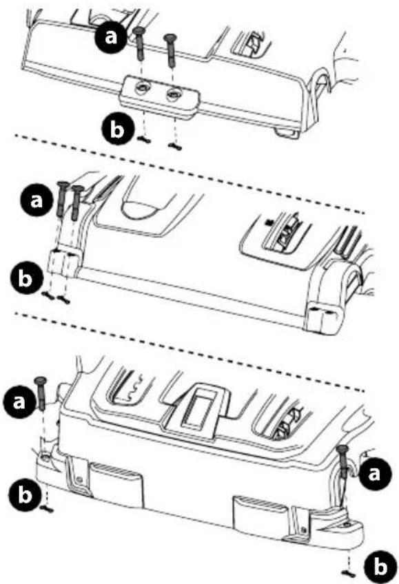
TO REMOVE SKID SHOES (DELUXE SHOWN):
-
Remove four carriage bolts (a) and hex flange nuts (b) and flat washers (c) which secure them to the housing.
-
Rotate and reassemble new skid shoes with four carriage bolts (a) (two on each side) and hex flange nuts (b) and flat washers (c) (Figure 80).
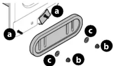
text_image
a a c b c bFigure 80
TO REMOVE SHAVE PLATE:
- Allow the engine to run until it is out of fuel. Do not attempt to drain fuel from the engine. Remove safety key or disconnect spark plug wire.
- Carefully pivot snow blower up and forward so that it rests on the auger housing.
- Remove carriage bolts (a) and hex nuts (b) which attach it to auger housing (Figure 81).
text_image
Technical diagram of a mechanical gear or worm gear assembly with labeled parts 'a' and 'b', showing internal gear structure and alignment indicators.Figure 81
- Reassemble new shave plate, making sure heads of carriage bolts are to the inside of housing. Tighten securely (Figure 81).
- If adjusting the shave plate is necessary, refer to Adjustable Shave Plate (If Equipped) on page 16.
Off-Season Storage
If the snow blower will no longer be used until next season, follow the storage instructions below.
- Run engine until fuel tank is empty and it stops due to lack of fuel. Do not attempt to drain fuel from engine.
- Fill the tank with Fresh, ethanol free fuel treated with a fuel stabilizer or *bottled alcohol free fuel available at your local power equipment retailer.
*NOTE: TruFuel® highly recommended. TruFuel® pre-formulated, canned fuels include fuel stabilizers, do not contain any ethanol, and are sealed to maintain freshness.
- Run engine for 5 – 10 minutes to ensure the old fuel has been removed from the fuel system.
NOTE: Refer to Engine Operator's Manual for information on storing your engine.
NOTE: If equipped, remove battery before storage. See Installing/Removing The Battery Pack on page 19.
- Lubricate machine as instructed on page 28.
- Store in a clean, dry area.
- If storing in an unventilated area, rustproof machine using a light oil or silicone to coat the snow blower.
- Clean the exterior of the engine and the snow blower.
IMPORTANT: When storing or when it is not being serviced, it is to remain in the upright position with both wheels and auger housing on the ground.
LUBRICATION
Wheels
At least once a season, remove both wheels. Clean and coat axles with a multipurpose automotive grease before reinstalling wheels.
Side Mounted Chute ROTATION Control (If Equipped)
Once a season, lubricate eye-bolt bushing and the spiral with 3-in-1 oil.
Non-Hydro Models (If Equipped)
The friction wheel hex shaft should be lubricated at least once a season or after every twenty-five (25) hours of operation.
- Allow engine to run until it is out of fuel. Remove safety key or disconnect spark plug wire.
- Carefully pivot snow blower up and forward so that it rests on auger housing.
- Remove frame cover from underside by removing self-tapping screws (Figure 82).
natural_image
Diagram of a ship's internal structure with directional arrows indicating movement or force (no text or symbols present)Figure 82
- Apply a light coating of Bostik Regular Grade Never-Seez® to hex shaft (Figure 83).
natural_image
Mechanical assembly diagram showing a gear and shaft assembly with a black arrow indicating motion direction (no text or labels)Figure 83
NOTE: When lubricating hex shaft, be careful not to get any lubricant on aluminum drive plate or rubber friction wheel. Doing so will affect the drive system. Wipe off any excess or spilled lubricant.
PRODUCT CARE
Auger Shaft
At least once a season, remove shear pins (a) and cotter pins (b) from auger shaft(s). Spray lubricant inside shaft and around spacers and flange bearings found at either end of shaft(s) (Figure 84).
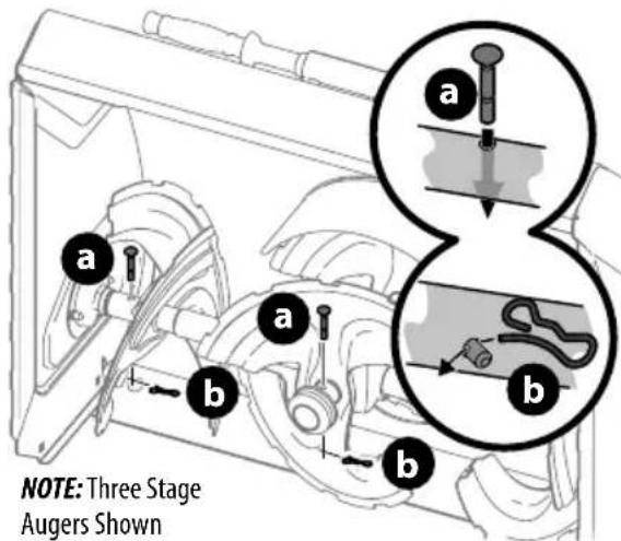
text_image
NOTE: Three Stage Augers ShownFigure 84
IMPORTANT: On 3-stage models, there is an additional shear pin in the rear accelerator.
SERVICE
NOTE: If equipped with cordless battery start, remove battery before performing Service. See Installing/Removing The Battery Pack on page 19.
Auger Belt Replacement
To remove and replace auger belt, proceed as follows:
- Allow engine to run until it is out of fuel. Do not attempt to drain fuel from engine. Remove safety key or disconnect spark plug wire.
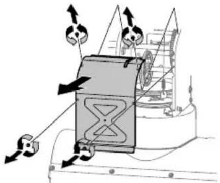
- Remove plastic belt cover on front of engine by removing two self-tapping screws (a) (Figure 85).
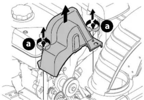
text_image
Technical diagram of a mechanical assembly with labeled parts 'a' and directional arrows indicating motion or force vectors.Figure 85
NOTE: On models equipped with the LED light bar on top of the auger housing, make sure to unplug the wire harness before removing the belt cover (Figure 86).
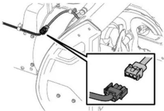
natural_image
Technical diagram showing connector assembly with a close-up inset of a terminal block (no text or symbols present)Figure 86
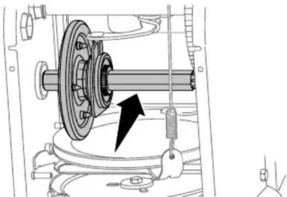
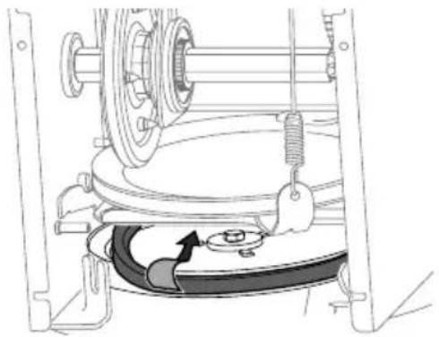
- Roll auger belt off engine pulley (Figure 87).
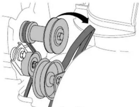
natural_image
Mechanical assembly diagram showing a belt drive mechanism with pulleys and a belt (no text or labels)Figure 87
- Carefully pivot the snow blower up and forward so that it rests on the auger housing.
- Remove frame cover from underside by removing self-tapping screws (Figure 82).
- Loosen and remove shoulder bolt (b) which acts as a belt keeper and unhook the spring (c) from the frame (Figure 88).
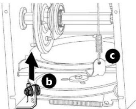
text_image
Technical diagram of a mechanical assembly with labeled parts b, c, and an arrow indicating direction or force.NOTE: Multi-speed unit shown.
Figure 88
- Remove belt from around auger pulley, and slip it between support bracket and auger pulley (Figure 89).
natural_image
Technical line drawing of a mechanical assembly with gears and a belt, no visible text or symbolsFigure 89
NOTE: Engaging auger control will ease removal and reinstallation of belt.
- Replace auger belt by following instructions in reverse order.
NOTE: Make sure to reinstall shoulder bolt (a) and reconnect spring to frame after installing a replacement auger belt (Figure 88).
- After replacing auger belt, test the auger control. Refer to Auger Control on page 17.
Drive Belt Replacement
NOTE: See your authorized service dealer to have drive belt replaced or contact Customer Support.
Friction Wheel Inspection (Steerable 500 and 800 Series & Non-Steerable Single Speed 600 Series)
If snow blower fails to drive with drive control lever engaged, and performing drive control cable adjustment fails to correct problem, the friction wheel may need to be replaced.
IMPORTANT: Special tools are required and several components must be removed in order to replace the friction wheel rubber. See your authorized service dealer to have friction wheel rubber replaced or contact Customer Support.
To inspect friction wheel, proceed as follows:
- Allow engine to run until it is out of fuel. Do not attempt to drain fuel from engine. Remove safety key or disconnect spark plug wire.
- Carefully pivot snow blower up and forward so that it rests on auger housing.
- Remove frame cover from underside by removing four self-tapping screws (Figure 82).
- Inspect friction wheel for signs of wear or cracking.
- Using the four self tapping screws, reinstall the frame cover (Figure 82).
- If friction wheel rubber must be replaced see your authorized service dealer to have friction wheel rubber replaced or contact Customer Support.
Friction Wheel Removal (Multi-Speed Non-Steerable 600 Series)
If snow blower fails to drive with drive control lever engaged, and performing drive control cable adjustment fails to correct the problem, friction wheel may need to be replaced. Follow the instructions below. Examine friction wheel for signs of wear or cracking and replace if necessary.
- Allow engine to run until it is out of fuel. Do not attempt to drain fuel from engine. Remove safety key or disconnect spark plug wire.
- Place shift lever in first Forward (F1) position.
- Carefully pivot snow blower up and forward so that it rests on auger housing.
- Remove frame cover from underside by removing self-tapping screws (Figure 82). Remove right-hand wheel by removing screw and bell washer which secure it to axle. See (Figure 90).
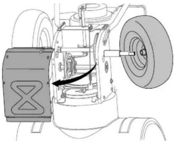
natural_image
Technical diagram of an aircraft fuselage showing internal components and a directional arrow (no text or labels)Figure 90
- Carefully remove hex nut (a) which secures hex shaft to frame and lightly tap the shaft's end to dislodge ball bearing from right side of frame (Figure 91).
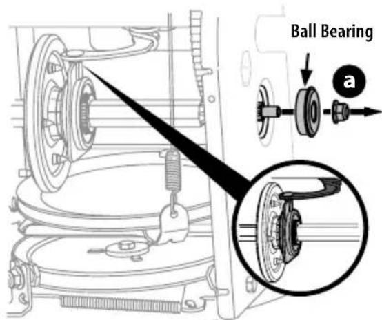
text_image
Ball Bearing aFigure 91
NOTE: Be careful not to damage threads on shaft.
PRODUCT CARE
- Carefully position hex shaft downward and to left before carefully sliding friction wheel assembly off shaft (Figure 92).
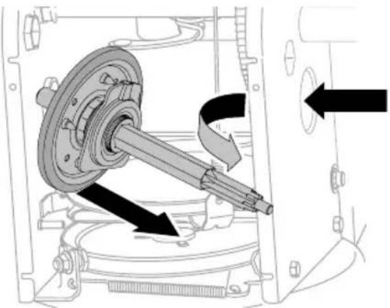
natural_image
Mechanical assembly diagram showing a shaft and housing with directional arrows indicating motion (no text or symbols)Figure 92
NOTE: If you're replacing friction wheel assembly as a whole, discard the worn part and slide new part onto hex shaft.
- Follow previous steps in reverse order to reassemble components.
- Perform Drive Control test shown on page 18.
If you're disassembling friction wheel and replacing only rubber ring, proceed as follows:
NOTE: Not all friction wheels are serviceable. If this is the case, simply replace friction wheel assembly.
9. Remove four screws (b) which secure friction wheel's side plates together (Figure 93).
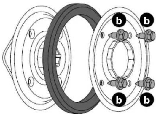
natural_image
Technical diagram of a mechanical assembly showing two bearing housing components with bolted joints (no text or labels)Figure 93
- Remove rubber ring from between the plates.
- Reassemble side plates with a new rubber ring.
NOTE: When reassembling friction wheel assembly, make sure that rubber ring is centered and seated properly between the side plates. Tighten each screw only one rotation before turning wheel clockwise and proceeding with next screw. Repeat this process several times to ensure plates are secured with equal force (between 115-145 in-lbs).
- Apply a light coating of Bostik Regular Grade Never-Seez ^® to hex shaft.
- Slide friction wheel assembly back onto hex shaft and follow the steps above in reverse order to reassemble components.
- After replacing friction wheel, perform Drive Control test shown on page 18.
NOTE: Make sure shift lever pin is in place in bearing housing (Figure 91 inset).
Hydro Transmission (If Equipped)
NOTE: See your authorized service dealer to have the Hydro Transmission serviced or contact Customer Support for assistance and the name of your nearest servicing dealer.
BATTERY DISPOSAL
IMPORTANT: Refer to instructional manual supplied with battery charger for disposal instructions.
Manual del Operador
Soplador de Nieve
natural_image
Mechanical assembly diagram showing two views of a vehicle's suspension components (no text or labels)Figura 3
natural_image
Illustration of a helicopter hovering above a tracked vehicle, with no visible text or symbolsFigura 4
natural_image
Technical line drawing of a mechanical component with no visible text or symbolsFigura 7
natural_image
Technical line drawing of a mechanical assembly with a downward arrow indicating a component (no text or symbols present)Figura 9
natural_image
Technical line drawing of a mechanical component with mounting bracket and wiring (no text or symbols)Figura 10
text_image
Technical diagram showing two mechanical assembly steps labeled a and b, with arrows indicating motion direction.Figura 11
text_image
Technical diagram of a vehicle seatbelt mechanism with labeled parts and directional arrows indicating movement or assembly.text_image
Technical diagram of a mechanical assembly with labeled parts (a, b) and an inset showing a component detail.natural_image
Technical line drawing of a mechanical clamp or lever assembly (no text or symbols)text_image
Diagram showing mechanical assembly with labeled parts (a) and (b), including a magnified inset view of a tool interacting with a component.Figura 17
natural_image
Mechanical assembly diagram showing a lever mechanism inside a housing component, with no visible text or symbols.Figura 20
text_image
Technical diagram of a mechanical assembly with labeled components and an inset showing a close-up of a component detail.Figura 21
text_image
Diagram showing car intake and exhaust system with labeled components and directional arrows indicating flow or movement.Figura 23
text_image
Diagram showing a car interior with a highlighted section of the seatbelt, including a magnified inset of the seatbelt detail.Figura 24
text_image
Diagram showing a mechanical device being inserted into a housing, with a magnified inset highlighting the component's detail.Figura 25
text_image
Technical diagram of a mechanical assembly with labeled parts (a, b) and an inset showing a close-up of a component detail.Figura 28
text_image
Technical diagram showing a mechanical component with labeled parts (a, b) and an inset view of a plug inserted into a housing.Figura 29
natural_image
Technical diagram of a car's front wheel assembly showing internal components and a close-up view of the engine (no text or labels)Figura 30
text_image
Technical diagram showing mechanical assembly with an arrow indicating direction and a magnified inset highlighting a component detail.Figura 31
Varilla de cambio (si viene equipados)
text_image
Technical diagram showing mechanical assembly with labeled parts (a, b, c, d, e, f) and directional arrows indicating movement or force.Figura 32
natural_image
Mechanical assembly diagram showing a tool inserted into a housing component, with magnified detail highlighting the mechanism (no text or symbols present)Figura 36
text_image
Technical diagram of a mechanical assembly with labeled parts (d, e) and an inset showing a close-up of a component.Figura 37
text_image
Technical diagram of a mechanical assembly with labeled parts (b and c) and directional arrows indicating movement or force.Figura 38
text_image
Technical diagram showing mechanical assembly with an arrow indicating direction and a magnified inset highlighting a component being inserted.Figura 39
text_image
Diagram showing a mechanical device with labeled parts and an inset magnified view of the component being inserted.Figura 40
text_image
Medical diagram showing surgical procedure with labeled parts a and c, likely for laparoscopic or endoscopic procedures.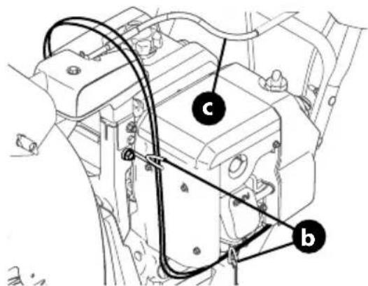
text_image
Technical diagram of a mechanical assembly with labeled components (a, b, c) and connection linesFigura 41
text_image
Technical diagram showing three labeled mechanical assembly steps (a, b) for assembly or maintenance instructions.Figura 42
natural_image
Diagram of a mechanical device with labeled parts (a and b), showing internal components and motion lines without any readable text or symbols.Figura 43
text_image
Technical diagram showing a mechanical component with labeled parts (a) and (b), likely illustrating assembly or assembly steps.natural_image
Technical line drawing of a mechanical assembly with threaded components (no text or symbols)Figura 46
natural_image
Technical diagram showing a mechanical component with labeled parts (a and b), no readable text or symbols present.Figura 48
natural_image
Illustration of a car seatbelt being adjusted with arrows indicating rotation (no text or symbols)Figura 49
natural_image
Diagram of a mechanical device with rotating shaft and spring, showing motion direction (no text or symbols)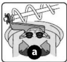
natural_image
Diagram of a mechanical device with a spring and labeled component 'a' (no text or symbols beyond label)Figura 50
Control del Canal Superior (si viene equipado)
text_image
Technical diagram of a mechanical assembly with labeled parts (a and b) and an inset showing a circular component.Figura 51
text_image
Diagram showing a cable being inserted into a device, with labeled parts and directional arrows indicating assembly or inspection.Figura 52
text_image
Technical diagram showing mechanical assembly with labeled parts a and b, including a tool and directional arrow indicating motion or movement.Figura 55
text_image
Technical diagram showing mechanical assembly with labeled parts (a, b, c, d, e, F) and directional arrows indicating movement or assembly.Figure 56
text_image
Technical diagram showing mechanical assembly with labeled parts a and b, including directional arrows indicating movement or force.Figura 58
text_image
Technical diagram showing mechanical assembly with labeled parts a and b, including directional arrows indicating movement or force.Figura 59
natural_image
Line drawing of two electronic devices connected by a cable (no text or symbols)Figure 60
text_image
Technical diagram of a mechanical assembly with labeled components (a–f) and internal assembly views showing internal components.Figure 61
CARGA DE COMBUSTIBLE Y ACEITE
natural_image
Two black-and-white icons showing a knife and a tractor, with directional arrows indicating movement or force (no text or symbols)Figura 63
natural_image
Simple line drawing of a knife with an arrow indicating motion (no text or symbols)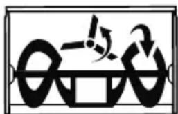
natural_image
Abstract black-and-white graphic with curved shapes and a central symbol (no text or symbols)Figura 64
natural_image
Diagram showing two identical mechanical or robotic arm configurations with directional arrows indicating movement (no text or symbols)Figura 65
text_image
Diagram illustrating magnetic field lines around a current-carrying conductor, showing rotational motion and magnetic polarity.Figura 66
text_image
Diagram illustrating magnetic field lines around a current-carrying conductor, showing rotational motion and magnetic polarity.Figura 67
text_image
Diagram illustrating a mechanical or electrical process with rotating components and directional arrows, possibly indicating rotation or movement.Figura 69
natural_image
Illustration of a robotic arm with rotating arms and motion arrows, showing no text or symbolsFigura 70
natural_image
Diagram showing two mechanical lever mechanisms with rotational and linear motion indicators (no text or symbols)Figura 71
text_image
Technical diagram showing mechanical assembly with labeled parts 'a' and a magnified inset view of a component detail.Figura 72
natural_image
Technical line drawing of a mechanical assembly with a tool and component (no text or symbols)Figura 73
natural_image
Illustration of a hand holding a knife with motion lines indicating heat or airflow (no text or symbols)Interruptor ENCENDIDO
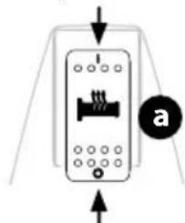
natural_image
Pure diagram of a device with directional arrows and a labeled circle (a), no text or symbols present.Interruptor APAGADO
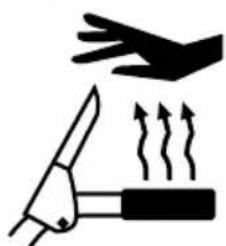
natural_image
Illustration of a knife and hand holding a tool with motion lines indicating movement (no text or symbols)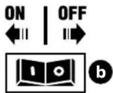
text_image
ON | OFF ←→ → bFigura 74
U. ARRANQUE SIN CUERDA A BATERÍA (SI ESTÁ EQUIPADO)
natural_image
Technical line drawing of a mechanical assembly with labeled component 'a' (no text or symbols beyond label)Figura 75
natural_image
Technical line drawing of a mechanical assembly with a lever and gear (no text or symbols)Figura 78
text_image
Diagram illustrating mechanical assembly steps with labeled components a and d, showing tool paths and cross-sections.text_image
Technical diagram of a mechanical assembly with labeled parts (a, b, c, d) and an inset showing a screw and shaft mechanism.Figura 79

ADVERTENCIA
text_image
Technical diagram of a mechanical device with labeled components and motion indicators, including parts a and b.Figura 81
natural_image
Diagram of a mechanical device with directional arrows indicating motion or force, no visible text or symbolsFigura 82
natural_image
Mechanical assembly diagram showing a gear and shaft assembly with a black arrow indicating motion direction (no text or labels)Figura 83
text_image
Technical diagram of a mechanical component with labeled parts 'a' and directional arrows indicating motion or assembly.Figura 85
natural_image
Technical diagram showing a car electrical connector with cable and socket, plus an inset view of a plug-in connector (no text or symbols present)Figura 86
natural_image
Mechanical assembly diagram showing a belt drive mechanism with pulleys and springs (no text or labels)Figura 87
text_image
Technical diagram of a mechanical assembly with labeled parts b, c, and an arrow indicating directionnatural_image
Mechanical assembly diagram showing a rotating component with spring and pulley (no text or symbols)Figura 89
natural_image
Technical diagram of a mechanical assembly with labeled components and an arrow indicating motion direction (no text or symbols present)Figura 90
natural_image
Mechanical assembly diagram showing a shaft and housing component with directional arrows indicating motion (no text or labels)Figura 92
natural_image
Technical diagram of a mechanical assembly with concentric rings and bolted components (no text or labels)Figura 93
Anglais (English)......Page 2
Français (French) Page 65
natural_image
Mechanical assembly diagram showing two views of a bicycle frame with mechanical components and structural details (no text or labels)Figure 3
natural_image
Illustration of a tracked agricultural machine with a helicopter above it, showing mechanical components and motion arrows (no text or symbols)Figure 4
natural_image
Technical line drawing of a mechanical component with no visible text or symbolsFigure 7
ASSEMBLAGE
COMMANDE LATÉRALE DE ROTATION ET COMMANDE MANUELLE DE DÉFLECTEUR
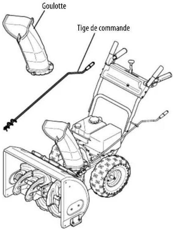
text_image
Goulotte Tige de commandeFigure 8
natural_image
Technical illustration of a mechanical assembly with a downward arrow indicating a component (no text or symbols present)Figure 9
natural_image
Technical line drawing of a mechanical assembly with no visible text or symbolsFigure 10
text_image
Technical diagram showing two mechanical assembly steps labeled a and b, with arrows indicating motion direction.Figure 11
text_image
Technical diagram of a vehicle intake system with labeled components and a magnified inset showing internal components.text_image
Technical diagram of a mechanical device with labeled parts (a, b) and an inset showing a cross-section detail.natural_image
Technical line drawing of a mechanical clamp or lever assembly (no text or symbols)text_image
Technical diagram showing mechanical assembly with labeled parts (a) and (b), including a magnified inset view of the component.natural_image
Mechanical assembly diagram showing a tool inserted into a housing component, with no visible text or symbols.text_image
Technical diagram of a mechanical assembly with labeled components and an inset magnified view showing a close-up detail.text_image
Diagram showing car intake and exhaust system with labeled components and directional arrows indicating flow or movement.Figure 23
text_image
Diagram showing a car interior with a highlighted section and directional arrow, likely illustrating vehicle or mechanical components.Figure 24
text_image
Technical diagram showing a mechanical component being inserted into a housing, with labeled parts and directional arrow.Figure 25
text_image
Technical diagram of a mechanical assembly with labeled parts (a, b) and an inset showing a close-up of a component detail.Figure 28
text_image
Diagram of a car fuel injector with labeled parts and an inset showing the internal component being inserted into a plug.Figure 29
natural_image
Diagram of a car's frontview and side arm assembly, showing mechanical components and a magnified view of the engine shaft (no text or labels)Figure 30
text_image
Technical diagram showing mechanical assembly with an arrow indicating direction and a magnified inset highlighting a component detail.Figure 31
text_image
Technical diagram showing mechanical assembly with labeled parts (a, b, c, d, e) and directional arrows indicating movement or assembly.Figure 32
natural_image
Mechanical assembly diagram showing a valve inserted into a housing with a black arrow indicating direction (no text or symbols)
Sans transmission hydrostatique
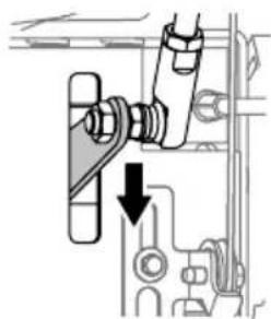
natural_image
Mechanical assembly diagram showing a lever mechanism with a downward arrow indicating motion (no text or symbols present)
Transmission hydrostatique
Figure 33
natural_image
Mechanical assembly diagram showing a tool inserted into a housing component, with no visible text or symbols.Figure 36
text_image
Technical diagram of an engine component with labeled parts and a magnified inset showing a mechanical assembly detail.Figure 37
text_image
Technical diagram showing mechanical assembly with labeled parts (b, c) and directional arrows indicating motion or movement.Figure 38
natural_image
Mechanical assembly diagram showing a bolt and nut assembly with an inset close-up of a mechanical component (no text or symbols)Figure 39
text_image
Diagram showing a mechanical component being inserted into a device, with labeled parts and directional arrows indicating assembly or inspection.Figure 40
text_image
Technical diagram showing cable installation and wiring connections in a vehicle engine compartment, labeled with points a, b, and c.Figure 41
text_image
Technical diagram showing car interior components with labeled parts (a, b) and assembly stepsFigure 42
natural_image
Diagram of a mechanical device with labeled parts (a and b), showing internal components and motion lines without any readable text or symbols.Figure 43
natural_image
Technical line drawing of a mechanical assembly with threaded components (no text or symbols)Figure 46
text_image
Technical diagram showing a mechanical component with labeled parts (a) and (b), including a close-up inset of the internal structure.Figure 48
natural_image
Illustration of a mechanical device with rotating components (no text or symbols)Figure 49
natural_image
Diagram showing a mechanical spring with motion arrows and a close-up of a gear mechanism (no text or symbols)Figure 50
text_image
Technical diagram showing mechanical assembly with labeled parts a and b, including a magnified inset view of a component.Figure 51
text_image
Diagram showing a mechanical device with labeled parts and an inset magnified view of the component being inserted.Figure 52
text_image
Technical diagram of a mechanical clamp or bracket with labeled parts (a and b) and directional arrow indicating motion or movement.Figure 55
text_image
Technical diagram showing mechanical assembly with labeled parts (a, b, c, d, e, f) and directional arrows indicating movement or assembly.Figure 56
text_image
Technical diagram of a mechanical assembly with labeled parts a and b, showing directional arrows and components.Figure 58
text_image
Technical diagram showing mechanical assembly with labeled parts a and b, including directional arrows and circular features.Figure 59
natural_image
Technical line drawing of two electronic components connected by a cable (no text or symbols)Figure 60
Installation/retrait du bloc-batterie
- Installation du bloc-batterie (Figure 61):
text_image
Technical diagram of an electrical switchgear assembly with labeled components and directional arrows indicating movement or assembly.Figure 61
CARBURANT ET HUILE
natural_image
Two black-and-white icons showing a tool and a tractor, with no text or symbols present.Figure 63
natural_image
Two identical diagrams showing a vehicle with directional arrows indicating motion or force, no text or symbols present.Figure 65
UTILISATION
text_image
Diagram illustrating a mechanical or electrical process with rotating components and a magnified view of a device with a circular symbol.Figure 66
L. COMMANDE SUPÉRIEURE DE GOULOTTE (SI PRÉSENT)
text_image
Diagram illustrating a mechanical or electrical concept with labeled components and directional arrows, possibly indicating motion or force.Figure 67
M. COMMANDE DU DÉFLECTEUR DE GOULOTTE (SI PRÉSENT)
text_image
Diagram illustrating a mechanical or electrical operation with labeled components and directional arrowsFigure 69
O. COMMANDE DE GOULOTTE À 4 DIRECTIONS (SI PRÉSENT)
natural_image
Illustration of a robotic arm with rotating arms and a curved handle, showing motion direction (no text or symbols)Figure 70
UTILISATION
P. COMMANDE ÉLECTRIQUE DE GOULOTTE ET DE DÉFLECTEUR D'ÉJECTION (SI PRÉSENT)
natural_image
Diagram showing two robotic arm movements with rotating arms and base mount (no text or symbols)Figure 71
Q. COMMANDE MANUELLE DE GOULOTTE ET COMMANDE ÉLECTRIQUE DU DÉFLECTEUR (SI PRÉSENT)
text_image
Diagram showing car gear shift mechanism with labeled parts 'a' and a magnified inset view of the component.Figure 72
natural_image
Technical line drawing of a mechanical assembly with a hand holding a cable (no text or symbols)Figure 73
R. BARRE DE PHARES DEL (SI PRÉSENT)
natural_image
Technical line drawing of a mechanical assembly with labeled component 'a' (no text or symbols beyond label)Figure 75
natural_image
Technical line drawing of a mechanical component with a tool inserted, showing internal components and motion arrows (no text or symbols)Figure 78
REMPLACEMENT DES GOUPILLES DE CISAILLEMENT

ATTENTION
text_image
Diagram illustrating mechanical assembly with labeled parts a and d, showing directional arrows and componentstext_image
Diagram of a mechanical assembly with labeled parts (a, b, c, d) and directional arrows indicating movement or force.Figure 79

AVERTISSEMENT
Vibrations excessives
text_image
Technical diagram showing mechanical assembly with labeled components a and b, including directional arrows and circular annotations.Figure 81
natural_image
Diagram of a ship's internal structure with directional arrows indicating movement or force (no text or symbols)Figure 82
natural_image
Mechanical assembly diagram showing a gear and shaft assembly with an arrow indicating motion direction (no text or labels)↓
RÉVISION ET ENTRETIEN
Figure 83
text_image
Technical diagram showing mechanical component with labeled parts 'a' and directional arrows indicating movement or assembly.Figure 85
natural_image
Diagram showing cable connection to a vehicle component with an inset close-up of a connector (no text or symbols visible)Figure 86
natural_image
Mechanical assembly diagram showing a belt drive system with pulleys and springs (no text or labels)Figure 87
natural_image
Mechanical diagram showing a car wheel and attached gear assembly with an arrow indicating motion (no text or symbols)Figure 89
natural_image
Mechanical assembly diagram showing a vehicle's internal components with a gear and tire assembly (no text or labels)Figure 90