K 1270 II Rail - Saw HUSQVARNA - Free user manual and instructions
Find the device manual for free K 1270 II Rail HUSQVARNA in PDF.
| Product type | Rail saw (portable cut-off saw) |
| Brand | Husqvarna |
| Model | K 1270 II Rail |
| Displacement | 119 cm³ (7.3 cu in) |
| Power | 5.8 kW / 7.9 hp at 8,400 rpm |
| Idle speed | 2,700 rpm |
| Full throttle speed (no load) | 9,300 rpm (±150) |
| Fuel tank capacity | 1.2 L (40 US fl oz) |
| Weight (without fuel or blade, with 350 mm blade) | 15.3 kg (33.7 lb) |
| Weight (without fuel or blade, with 400 mm blade) | 16.0 kg (35.3 lb) |
| Weight of RA 10 rail attachment | 5.5 kg (12.1 lb) |
| Max spindle speed (350 mm blade) | 4,700 rpm |
| Max spindle speed (400 mm blade) | 4,300 rpm |
| Recommended blade diameter | 350 mm (14") or 400 mm (16") |
| Max cutting depth (350 mm blade) | 118 mm (4.6") |
| Max cutting depth (400 mm blade) | 145 mm (5.7") |
| Max blade thickness | 5 mm (0.2") |
| Blade arbor hole diameter | 25.4 mm (1") or 20 mm (0.79") |
| Cylinder bore | 60 mm (2.4") |
| Piston stroke | 42 mm (1.7") |
| Spark plug | NGK BPMR 7A (gap 0.5 mm) |
| Recommended water pressure | 0.5-10 bar (7-150 PSI) |
| Guaranteed sound power level | 117 dB(A) |
| Sound pressure level at ear | 104 dB(A) |
| Vibration level (front/back handle, 400 mm blade) | 4.4 / 3.9 m/s² |
| Fuel type | 2-stroke gasoline-oil mixture (50:1) |
| Intended use | Cutting rails, concrete, brick, stone, steel |
| Safety | Blade guard, SmartGuard (optional), trigger lock, emergency stop |
| Maintenance | Regular cleaning, replacement of air filter, spark plug, belt, etc. |
| Accessories | Wheel kit, Fleet Services sensor, rail attachment |
Frequently Asked Questions - K 1270 II Rail HUSQVARNA
User questions about K 1270 II Rail HUSQVARNA
0 question about this device. Answer the ones you know or ask your own.
Ask a new question about this device
Download the instructions for your Saw in PDF format for free! Find your manual K 1270 II Rail - HUSQVARNA and take your electronic device back in hand. On this page are published all the documents necessary for the use of your device. K 1270 II Rail by HUSQVARNA.
USER MANUAL K 1270 II Rail HUSQVARNA
K 1270 II, K 1270 II Rail, K 1270 SmartGuard
EN Operator's manual 2-42
Transportation, storage and disposal.... 38
Technical data.... 39
Accessories.... 40
Declaration of Conformity.... 41
Introduction
Product description
These HUSQVARNA, K 1270 II, K 1270 II Rail and K 1270 SmartGuard power cutters are portable handheld cut-off machines powered by 2-stroke combustion engines.
Intended use
The product is used to cut hard materials as concrete, masonry, stone and steel. K 1270 II Rail is specially
made to cut railroad tracks. Do not use the product for other tasks. The product must only be used by professional operators with experience.
Work is constantly in progress to increase your safety and efficiency during operation. Speak to your servicing dealer for more information.
Note: National/Local regulations could restrict the use of this product.
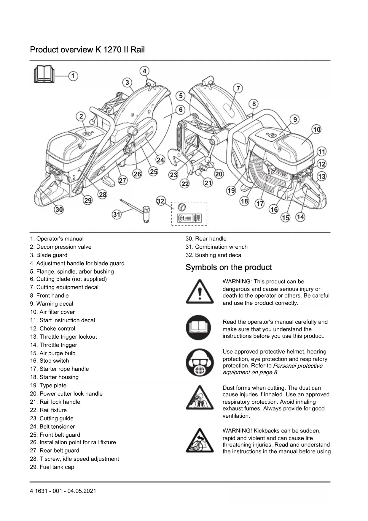
Product overview K 1270 II
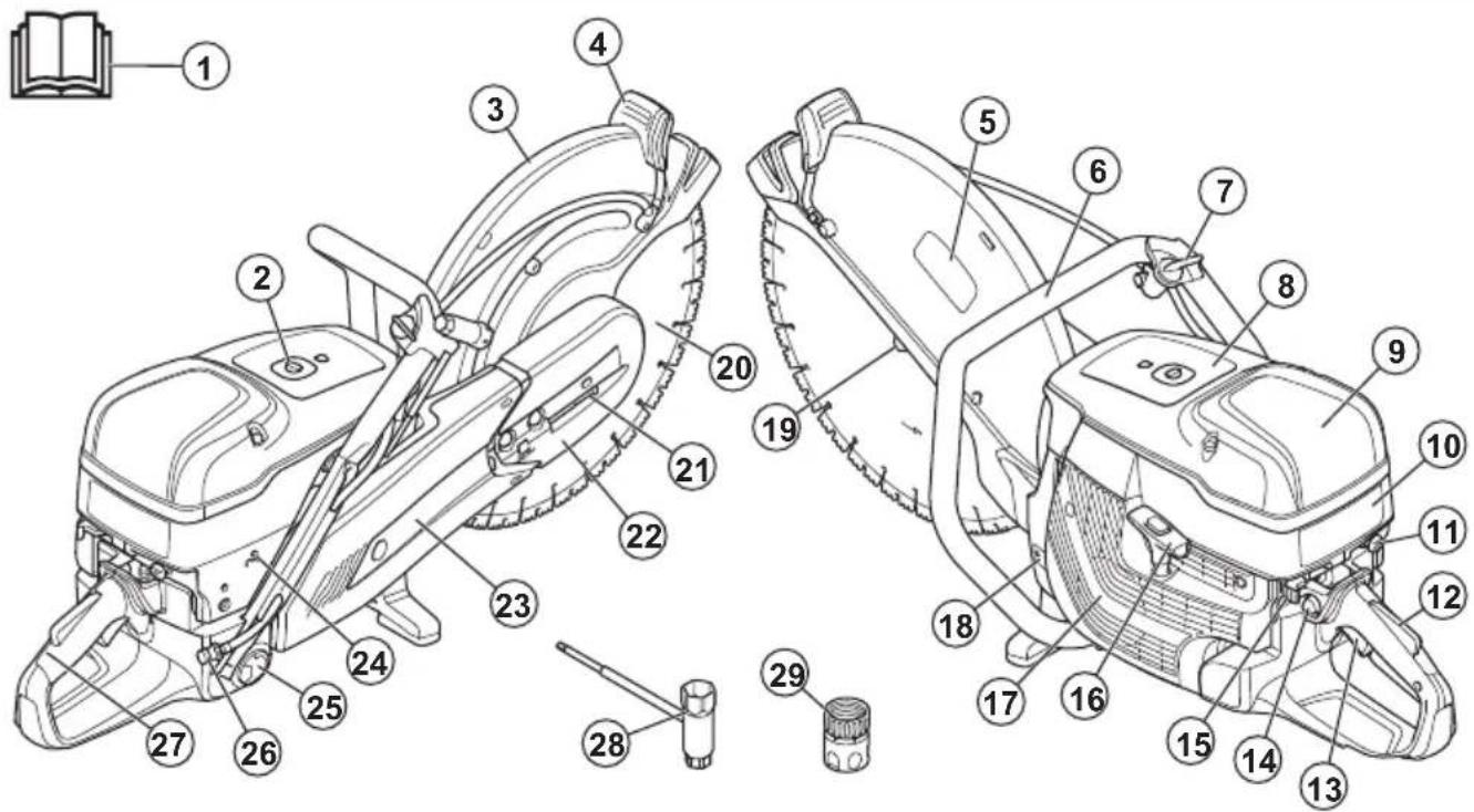
text_image
Technical diagram of a saw cutting machine with numbered parts for identification and assembly reference.- Operator's manual
- Decompression valve
- Blade guard
- Adjustment handle for blade guard
- Cutting equipment decal
- Front handle
- Water valve
-
Warning decal
-
Air filter cover
- Start instruction decal
- Choke control
- Throttle trigger lockout
- Throttle trigger
- Air purge bulb
- Stop switch
-
Starter rope handle
-
Starter housing
- Type plate
- Flange, spindle, arbor bushing
- Cutting blade (not supplied)
- Belt tensioner
- Front belt guard
-
Rear belt guard
-
T screw, idle speed adjustment
- Fuel tank cap
- Water connection with filter
- Rear handle
- Water connector Gardena®
- Combination wrench
Product overview K 1270 SmartGuard
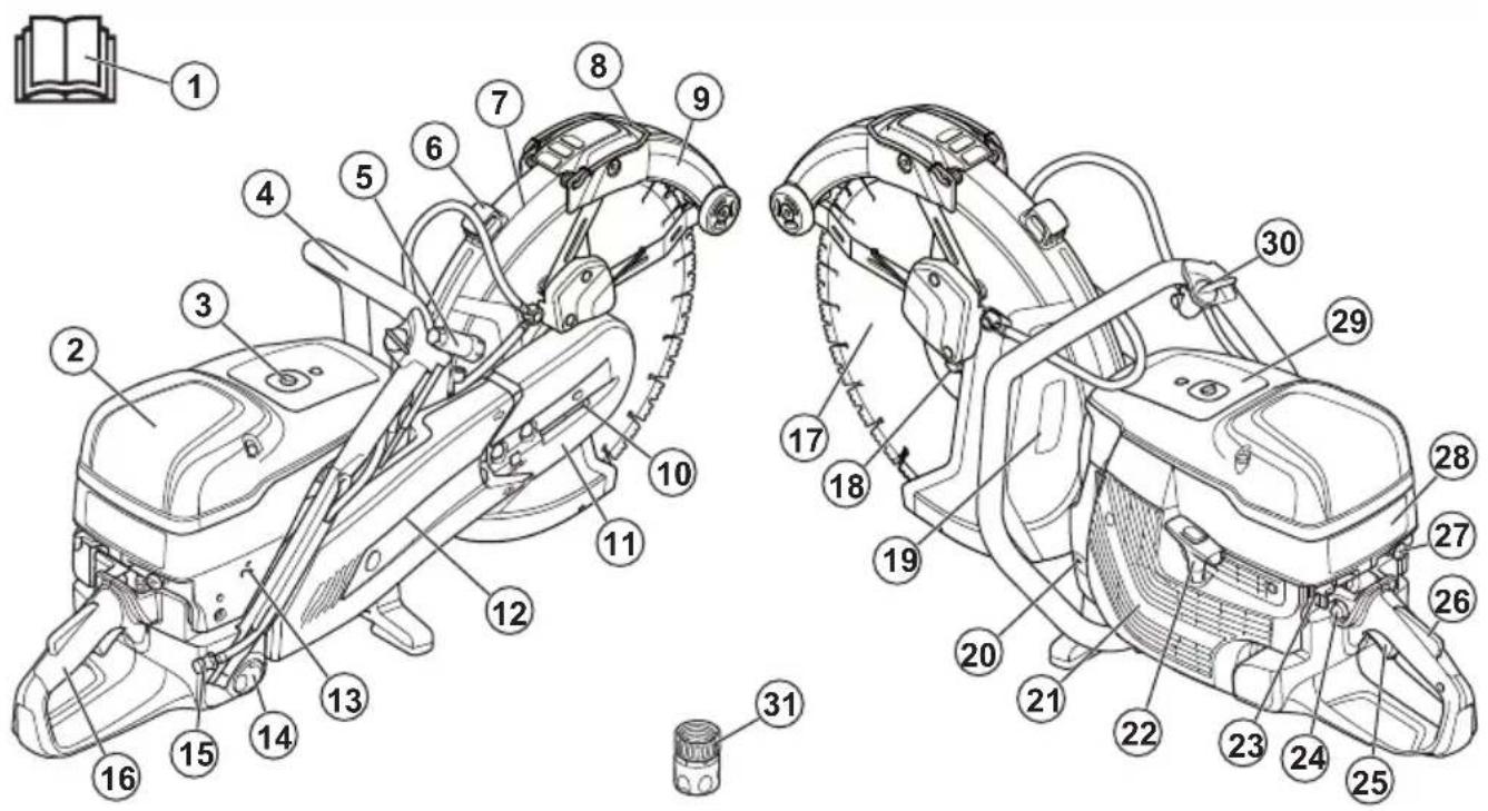
text_image
Technical diagram of a mechanical device with numbered parts, including a close-up inset of the book.- Operator's manual
- Air filter cover
- Decompression valve
- Front handle
- Combination wrench
- Adjustment handle for blade guard
- Blade guard
- SmartGuard handle
- SmartGuard
- Belt tensioner
- Front belt guard
- Rear belt guard
- T screw, idle speed adjustment
- Fuel tank cap
- Water connection with filter
-
Rear handle
-
Cutting blade (not supplied)
- Flange, spindle, arbor bushing
- Cutting equipment decal
- Type plate
- Starter housing
- Starter rope handle
- Stop switch
- Air purge bulb
- Throttle trigger
- Throttle trigger lockout
- Choke control
- Start instruction decal
- Warning decal
- Water valve
- Water connector Gardena®
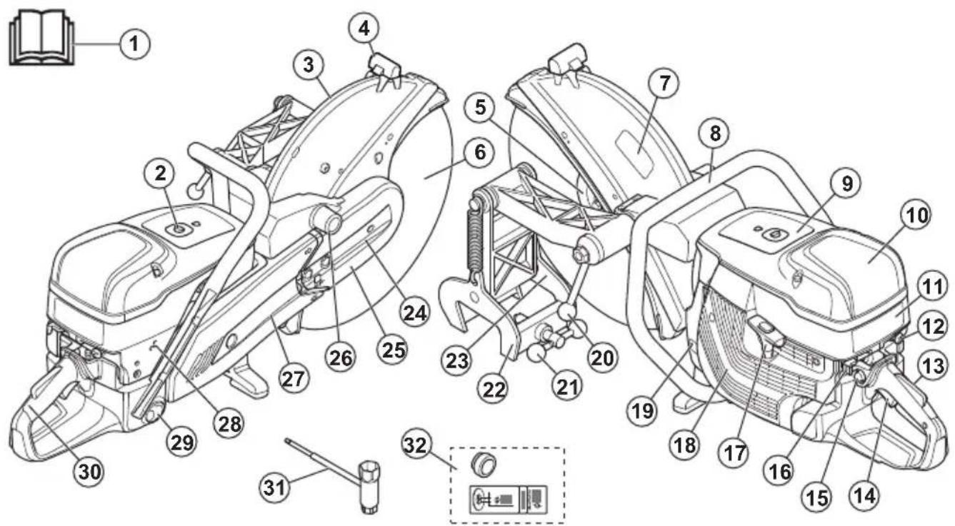
text_image
Technical diagram of a mechanical device with numbered parts, including a book icon and a control panel inset.- Operator's manual
- Decompression valve
- Blade guard
- Adjustment handle for blade guard
- Flange, spindle, arbor bushing
- Cutting blade (not supplied)
- Cutting equipment decal
- Front handle
- Warning decal
- Air filter cover
- Start instruction decal
- Choke control
- Throttle trigger lockout
- Throttle trigger
- Air purge bulb
- Stop switch
- Starter rope handle
- Starter housing
- Type plate
- Power cutter lock handle
- Rail lock handle
- Rail fixture
- Cutting guide
- Belt tensioner
- Front belt guard
- Installation point for rail fixture
- Rear belt guard
- T screw, idle speed adjustment
-
Fuel tank cap
-
Rear handle
- Combination wrench
- Bushing and decal
Symbols on the product

WARNING: This product can be dangerous and cause serious injury or death to the operator or others. Be careful and use the product correctly.

Read the operator's manual carefully and make sure that you understand the instructions before you use this product.

Use approved protective helmet, hearing protection, eye protection and respiratory protection. Refer to Personal protective equipment on page 8
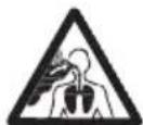
Dust forms when cutting. The dust can cause injuries if inhaled. Use an approved respiratory protection. Avoid inhaling exhaust fumes. Always provide for good ventilation.
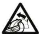
WARNING! Kickbacks can be sudden, rapid and violent and can cause life threatening injuries. Read and understand the instructions in the manual before using
the product. Refer to Kickback on page 16.
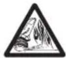
Sparks from the cutting blade can cause fire in fuel, wood, clothes, dry grass or other flammable materials.

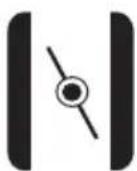
Make sure that the cutting blade does not have cracks or other damages.

Do not use circular saw blades.
Choke
Air purge bulb

Decompression valve
Starter rope handle
Use a fuel mixture of gasoline and oil.

This product complies with applicable EU Directives.
Noise emission to the environment complies with applicable EC Directives. The noise emission of the product is specified in Technical data on page 39 and on the label.
Note: Other symbols/decals on the product refer to special certification requirements for some markets.
Start instructions decal
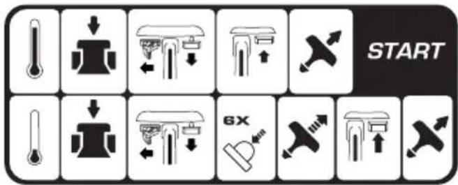
text_image
START 6XRefer to To start the product with a cold engine on page 22 and To start the product with a warm engine on page 24 for instructions.
Cutting equipment decal

text_image
max ③ ① ⑤ ⑤ ④ max ② rpm- Cutting blade diameter
- Max. speed of output shaft
- Max. blade thickness
- Direction of rotation
- Bushing dimension
Type plate
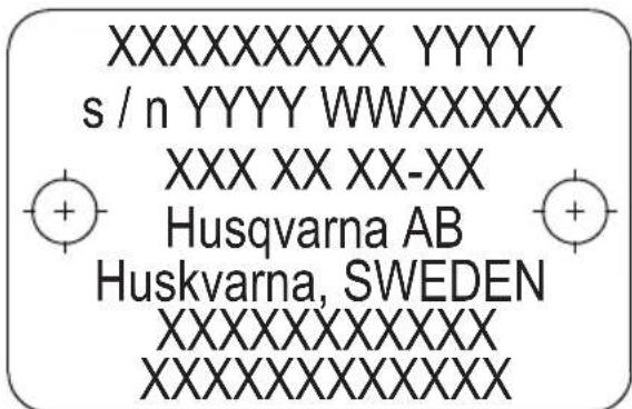
text_image
XXXXXXXX YYYY s / n YYYY WWXXXXX XXX XX XX-XX Husqvarna AB Huskvarna, SWEDEN XXXXXXXXXXXX XXXXXXXXXXXXXRow 1: Brand, Model (X, Y)
Row 2: Serial No. with manufacturing date (Y, W, X): Year, Week, Sequence No.
Row 3: Product No. (X)
Row 4: Manufacturer
Row 5: Manufacturer address
Rows 6–7: EU type approval or Chinese MEIN number

WARNING: Tampering with the engine voids the EU type-approval of this product.
Product liability
As referred to in the product liability laws, we are not liable for damages that our product causes if:
• the product is incorrectly repaired.
- the product is repaired with parts that are not from the manufacturer or not approved by the manufacturer.
- the product has an accessory that is not from the manufacturer or not approved by the manufacturer.
- the product is not repaired at an approved service center or by an approved authority.
Safety
Safety definitions
Warnings, cautions and notes are used to point out specially important parts of the manual.

WARNING: Used if there is a risk of injury or death for the operator or bystanders if the instructions in the manual are not obeyed.

CAUTION: Used if there is a risk of damage to the product, other materials or the adjacent area if the instructions in the manual are not obeyed.
Note: Used to give more information that is necessary in a given situation.
General safety instructions

WARNING: Read the warning instructions that follow before you use the product.
- A power cutter is a dangerous tool if used carelessly or incorrectly and can cause serious injury or death. It is very important that you read and understand the contents of this operator's manual. It is also recommended that first time operators also obtain practical instruction before using the product.
- Do not do modifications to this product. Modifications that are not approved by the manufacturer, can cause serious injury or death.
- Do not operate the product if it is possible that other persons have done modifications to the product.
• Always use original accessories and spare parts. Accessories and spare parts that are not approved by the manufacturer, can cause serious injury or death. - Keep the product clean. Make sure that you can clearly read signs and decals.
-
Never allow children or other persons not trained in the use of the product to use or service it.
-
Do not let a person operate the product unless they read and understand the contents of the operator's manual.
- Only let approved persons operate the product.
- This product produces an electromagnetic field during operation. This field can under some circumstances interfere with active or passive medical implants. To decrease the risk of serious injury or death, we recommend persons with medical implants to speak to their physician and the medical implant manufacturer before operating this product.
- The information in this operator's manual is never a substitute for professional skills and experience. If you are in a situation where you feel unsafe, stop and get expert advice. Speak to your servicing dealer. Do not try any task that you feel unsure of.
Safety instructions for operation

WARNING: Read the warning instructions that follow before you use the product.
- Before you use a power cutter, you must understand the effects of kickback and how to prevent them. Refer to Kickback on page 16.
- Do the safety checks, maintenance and servicing as given in this operator's manual. Some maintenance and servicing must be done by an approved service center. Refer to Introduction on page 27.
- Do not use the product if it is defective.
- Do not use the product if you are tired, ill, or under the influence of alcohol, drugs or medicine. These conditions can have an unwanted effect on your vision, alertness, coordination or judgment.
- Do not start the product without the belt and the belt guard installed. The clutch can become loose and cause injury.
- Sparks from the cutting blade can cause fire in flammable materials such as gasoline, gas, wood, clothes and dry grass.
- Do not cut asbestos material.

WARNING: Read the warning instructions that follow before you use the product.
- The safety distance for the power cutter is 15 m/50 ft. Make sure that animals and bystanders are not in the work area.
- Do not operate the product until the work area is clear and your feet and body are in a stable position.
- Look out for persons, objects and situations that can prevent safe operation of the product.
- Make sure that no persons or objects can come into contact with the cutting equipment or be hit by parts thrown by the blade.
- Do not use the product in fog, rain, strong winds, cold weather, risk of lightning or other bad weather conditions. To use the product in bad weather can have a negative effect on your alertness. Bad weather can cause dangerous work conditions, such as slippery surfaces.
- During operation of the product, make sure that no material can become loose and fall and cause injury to the operator.
- Be very careful when you operate the product on a slope.
- Keep the work area clean and bright.
- Before you operate the product, find out if there are hidden hazards such as electrical cables, water, and gas pipes and flammable substances in the work area. If the product hits a hidden object, stop the engine immediately and examine the product and the object. Do not start to operate the product again until you know that it is safe to continue.
- Before you cut into a drum, a pipe, or other container, make sure that it does not contain flammable or other material that can cause fire or explosion.
Vibration safety

WARNING: Read the warning instructions that follow before you use the product.
- During operation of the product, vibrations go from the product to the operator. Regular and frequent operation of the product can cause or increase the degree of injuries to the operator. Injuries can occur in fingers, hands, wrists, arms, shoulders, and/or nerves and blood supply or other body parts. The injuries can be debilitating and/or permanent, and can increase gradually during weeks, months or years. Possible injuries include damage to the blood circulation system, the nervous system, joints, and other body structures.
- Symptoms can occur during operation of the product or at other times. If you have symptoms and
continue to operate the product, the symptoms can increase or become permanent. If these or other symptoms occur, get medical aid:
- Numbness, loss of feeling, tingling, pricking, pain, burning, throbbing, stiffness, clumsiness, loss of strength, changes in skin color or condition.
- Symptoms can increase in cold temperatures. Use warm clothing and keep your hands warm and dry when you operate the product in cold environments.
- Do maintenance on and operate the product as given in the operator's manual, to keep a correct vibration level.
- The product has a vibration damping system that decreases the vibrations from the handles to the operator. Let the product do the work. Do not push the product with force. Hold the product at the handles lightly, but make sure that you control the product and operate it safely. Do not push the handles into the end stops more than necessary.
- Keep your hands on the handle or handles only. Keep all other body parts away from the product.
- Stop the product immediately if strong vibrations suddenly occurs. Do not continue the operation before the cause of the increased vibrations is removed.
- To cut granite or hard concrete causes more vibration in the product than if you cut soft concrete. Cutting equipment that is blunt, defective, of incorrect type or incorrectly sharpened, increases the vibration level
Exhaust fumes safety

WARNING: Read the warning instructions that follow before you use the product.
- The exhaust fumes from the engine contain carbon monoxide which is an odourless, poisonous and very dangerous gas. To breathe carbon monoxide can cause death. Because carbon monoxide is odourless and cannot be seen, it is not possible to sense it. A symptom of carbon monoxide poisoning is dizziness, but it is possible that a person becomes unconscious without warning if the quantity or concentration of carbon monoxide is sufficient.
- Exhaust fumes also contain unburned hydrocarbons including benzene. Long-term inhalation can cause health problems.
- Exhaust fumes that you can see or smell also contain carbon monoxide.
- Do not use a combustion engine product indoors or in areas that do not have sufficient airflow.
- Do not breathe the exhaust fumes.
- Make sure that the airflow in the work area is sufficient. This is very important when you operate the product in trenches or other small work areas where exhaust fumes can easily collect.
Dust safety

WARNING: Read the warning instructions that follow before you use the product.
- Operation of the product can cause dust in the air. Dust can cause serious injury and permanent health problems. Silica dust is regulated as harmful by several authorities. These are examples of such health problems:
• The fatal lung diseases chronic bronchitis, silicosis and pulmonary fibrosis
- Cancer
- Birth defects
- Skin inflammation
- Use correct equipment to decrease the quantity of dust and fumes in the air and to decrease dust on work equipment, surfaces, clothing and body parts. Examples of controls are dust collection systems and water sprays to bind dust. Decrease dust at the source where possible. Make sure that the equipment is correctly installed and used and that regular maintenance is done.
- Use approved respiratory protection. Make sure that the respiratory protection is applicable for the dangerous materials in the work area.
- Make sure that the airflow is sufficient in the work area.
- If it is possible, point the exhaust of the product where it cannot cause dust to go into the air.
Personal protective equipment

WARNING: Read the warning instructions that follow before you use the product.
- Always use approved personal protective equipment during operation. Personal protective equipment cannot eliminate the risk of injury but it will reduce the degree of injury if an accident does happen. Ask your servicing dealer for help in choosing the right equipment.
- Use an approved protective helmet.
- Use approved hearing protection. Long-term exposure to noise can result in permanent hearing impairment. Be aware of warning signals or shouts when you are wearing hearing protection. Always remove your hearing protection as soon as the engine stops.
- Use approved eye protection to decrease the risk of injury from thrown objects. If you use a face shield then you must also wear approved protective goggles. Approved protective goggles must comply with standard ANSI Z87.1 in the USA or EN 166 in EU countries. Visors must comply with standard EN 1731.
-
Use heavy duty gloves.
-
Use approved respiratory protection. The use of products such as cutters, grinders, drills, that sand or form material can generate dust and vapours which may contain hazardous chemicals. Check the nature of the material you intend to process and use appropriate breathing mask.
- Use tight-fitting, heavy-duty and comfortable clothing that permits full freedom of movement. Cutting generates sparks that can ignite clothing. HUSQVARNA recommends that you wear flame-retardant cotton or heavy denim. Do not wear clothing made of material such as nylon, polyester or rayon. If ignited such material can melt and cling to the skin. Do not wear shorts.
- Use boots with steel toe-cap and non-slip sole.
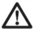
• Always keep a first aid kit near.
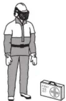
natural_image
Illustration of a person in full safety gear standing next to a first aid kit (no text or symbols visible)- Sparks can come from the muffler or the cutting blade. Always have a fire extinguishing available.
Safety devices on the product

WARNING: Read the warning instructions that follow before you use the product.
- Do not use a product with defective safety devices.
- Do a check of the safety devices regularly. If the safety devices are defective, speak to your HUSQVARNA approved service agent.
- Do not change the safety devices.
- Do not use the product if protective plates, protective covers, safety switches or other protective devices are defective or not attached.
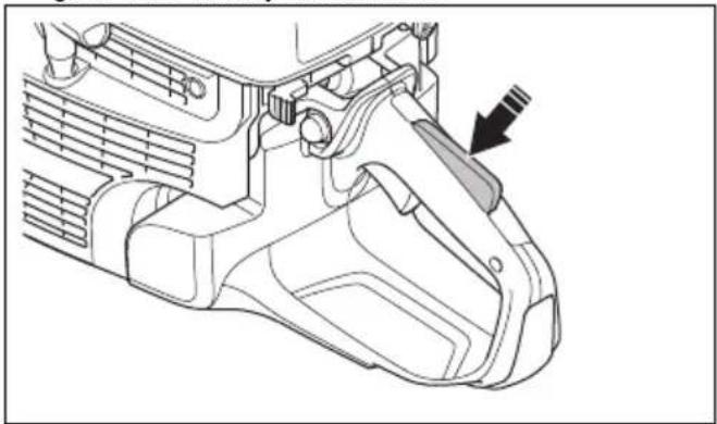
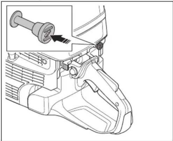
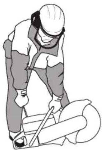
Throttle trigger lockout
The throttle trigger lockout prevents accidental operation of the throttle trigger. If you put your hand around the handle and push the throttle trigger lockout (A), it releases the throttle trigger (B). If you release the handle, the throttle trigger and the throttle trigger lockout
move back to their initial positions. This function locks the throttle trigger at idle speed.
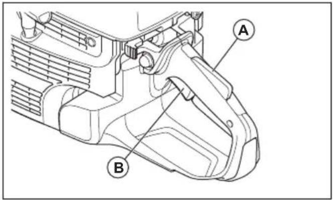
text_image
Technical diagram of a mechanical component with labeled parts A and BTo do a check of the throttle trigger lockout
- Make sure that the throttle trigger is locked at the idle position when the throttle trigger lockout is released.

natural_image
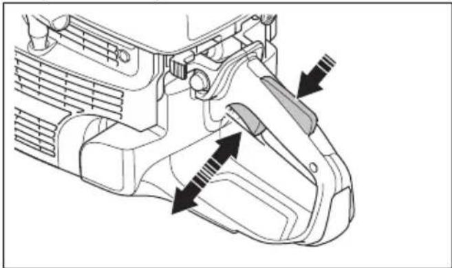
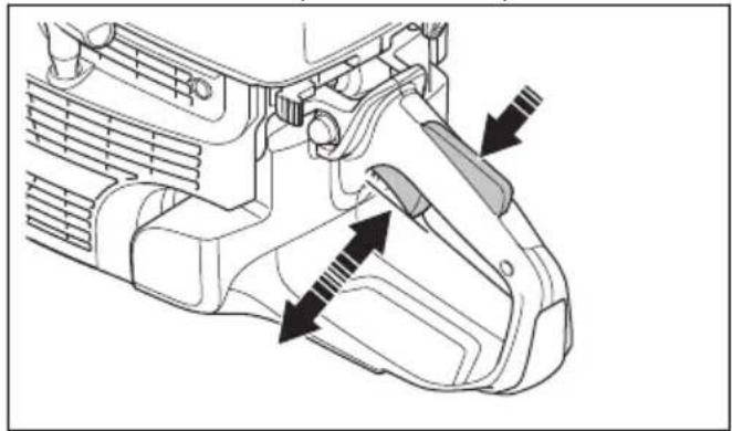
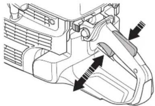
Technical line drawing of a mechanical component with an arrow indicating a specific feature (no text or symbols present)- Push the throttle trigger lockout and make sure that it goes back when you release it.
natural_image
Technical line drawing of a mechanical component with an arrow indicating a specific part (no text or symbols present)- Make sure that the throttle trigger and throttle trigger lockout move freely and that the return springs operate correctly.
natural_image
Technical line drawing of a mechanical component with directional arrows indicating movement or assembly (no text or symbols present)- Start the product and apply full throttle.
- Release the throttle control and make sure that the cutting blade stops and stays stationary.
- If the cutting blade rotates at idle position, adjust the idle speed. Refer to To adjust the idle speed on page 35.
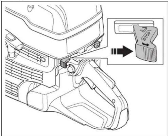
To do a check of the stop switch
- Start the engine.
- Push the stop switch to the STOP position. The engine must stop.
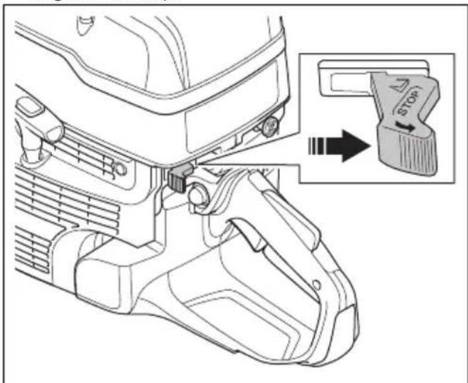
text_image
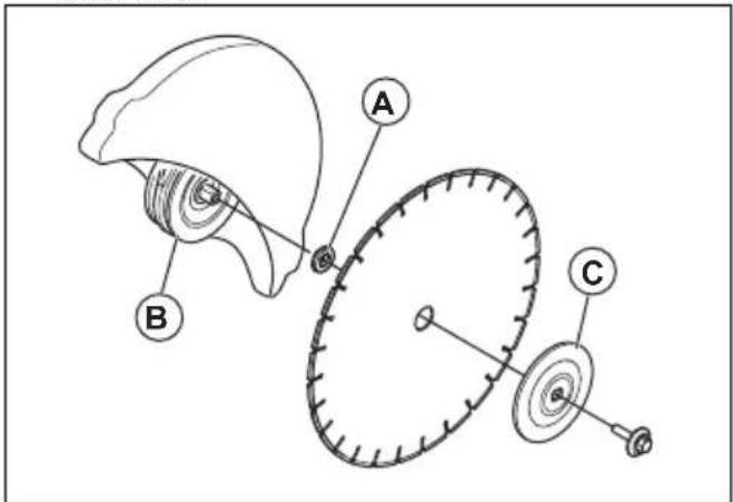
Technical diagram showing a mechanical component with an inset highlighting a stop button labeled 'Stop'.Blade guard and SmartGuard (Optional)
WARNING: Make sure that the blade guard and SmartGuard are correctly attached before you start the product. Do not use the product if the blade guard or SmartGuard is missing, defective or has cracks.
The blade guard (A) and SmartGuard (B) are installed above the cutting blade (C). They prevent injury if pieces
of the blade or cut material are thrown in the direction of the operator.
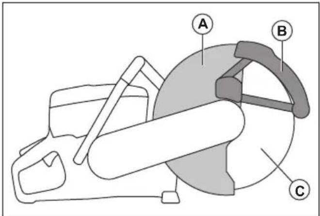
text_image
Diagram of a mechanical device with labeled parts A, B, and C, showing internal components and assembly.The SmartGuard is spring loaded and must always move freely and retract to its initial position by spring force.
To examine the blade and the blade guard
WARNING: A damaged cutting blade can cause injury.
- Make sure that the cutting blade is attached correctly and does not show signs of damage.
- Make sure that the blade guard has no cracks or is damaged.
- Replace the blade guard if it is damaged.
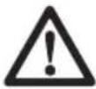
To do a check of the SmartGuard

WARNING: A damaged SmartGuard can cause injury.
CAUTION: The SmartGuard is a plastic guard and can become damaged by heat during intense dry cutting of metal with bonded abrasive blades. Do not do intense dry metal cutting and let the product become cool between the cuts. For intense metal cutting with SmartGuard, we recommend wet cutting together with vacuum brazed diamond blades, such as VARI-CUT FR3.
-
Make sure that the SmartGuard has no cracks or damage.
-
Make sure that the SmartGuard moves freely without much play and retracts by spring force.
natural_image
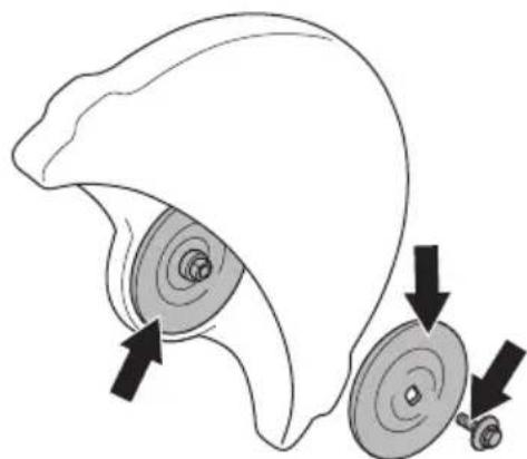
Diagram of a car steering wheel and dashboard with directional arrows indicating rotation (no text or symbols)- Clean or replace the SmartGuard if it does not retract immediately when pushed in, or is damaged.
Vibration damping system
Your product is equipped with a vibration damping system that is designed to minimize vibration and make operation easier. The product's vibration damping system reduces the transfer of vibration between the engine unit/cutting equipment and the product's handle unit.
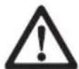
natural_image
Three types of threaded mechanical components shown in line drawings (no text or symbols)To do a check of the vibration damping system
WARNING: Make sure that the engine is off and that the stop switch is in STOP position.
- Make sure that there are no cracks or deformation on the vibration damping units. Replace the vibration damping units if they are damaged.
- Make sure that the vibration damping units are correctly attached to the engine unit and handle unit.
Muffler
The muffler keeps the noise levels to a minimum and sends the exhaust fumes away from the operator.
Do not use the product if the muffler is missing or defective. A defective muffler increases the noise level and the risk of fire.
WARNING: The muffler becomes very hot during and after use and when the engine operates at idle speed. Be careful
near flammable materials and/or fumes to prevent fire.
To do a check of the muffler
- Examine the muffler regularly to make sure that it is attached correctly and not damaged.
Fuel safety

WARNING: Read the warning instructions that follow before you use the product.
- Fuel is flammable and the fumes are explosive. Be careful with fuel to prevent injury, fire and explosion.
- Only refuel the product outdoors, where the airflow is sufficient. Do not breathe in the fuel fumes. The fuel fumes are poisonous and can cause injury, fire and explosion.
- Do not remove the fuel tank cap or fill the fuel tank when the engine is on.
- Let the engine become cool before you refuel.
- Do not smoke near the fuel or the engine.
- Do not put hot objects near the fuel or the engine.
- Do not fill fuel near sparks or flames.
- Before you refuel, open the fuel tank cap slowly and release the pressure carefully.
- Fuel on your skin can cause injury. If you get fuel on your skin, use soap and water to remove the fuel.
- If you spill fuel on your clothing, change clothing immediately.
- Tighten the fuel tank cap fully. If the fuel tank cap is not correctly tightened, the vibrations in the product can loosen it and cause leakage of fuel and fuel fumes. Fuel and fuel fumes are a risk of fire.
- Before you start the product, move the product to a minimum of 3 m/10 ft from where you refueled.
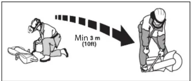
text_image
Min 3 m (10ft)- Do not start the product if there is fuel or oil spilled on the product. Remove the unwanted fuel and oil and let the product dry before you start the engine.
- Examine the engine for leaks regularly. If there are leaks in the fuel system, do not start the engine until the leaks are repaired.
- Keep fuel in approved containers only.
- When the product and fuel is in storage, make sure that fuel and fuel fumes cannot cause damage, fire and explosion.
- Drain the fuel in an approved container outdoors and away from sparks and flames.
Safety instructions for maintenance

WARNING: Read the warning instructions that follow before you use the product.
- Make sure that the engine is off and that the stop switch is in STOP position.
- Use personal protective equipment. Refer to Personal protective equipment on page 8.
- If the maintenance is not done correctly and regularly, the risk of injury and damage to the product increases.
- Only do the maintenance as given in this operator's manual. Let an approved service center do all other servicing.
- Let an approved HUSQVARNA service agent do servicing on the product regularly.
- Replace damaged, worn or broken parts.
• Always use original accessories.
Assembly
Cutting blades

WARNING: Always use protective gloves when you assemble the product.

WARNING: A cutting blade can break and cause injury to the operator.

WARNING: Examine the cutting blade for cracks, lost segments distortion or unbalance prior to use and immediately after
striking an unintended object. Do not use a damaged cutting blade. After inspecting and installing the cutting blade, position yourself and bystanders away from the plane of the rotating cutting blade and run the power tool at maximum no load speed for one minute.

WARNING: The cutting blade manufacturer gives warnings and recommendations for the operation and correct maintenance of the cutting blade. Those warnings are supplied with the cutting blade. Read and obey the instructions that are supplied with the cutting blade.
Applicable cutting blades

WARNING: Only use diamond blades and abrasive blades for concrete and metal. Do not use blades with serrations such as circular wood cutting blades or blades with carbide tips. The risk of kickback is increased and carbide tips can come off and be thrown at high speed. This can result in injury or death.

WARNING: Never use a cutting blade for any other materials than what it was intended to cut.
WARNING: Use only cutting blades that comply with applicable national or regional standards, for example EN12413, EN13236 or ANSI B7.1.

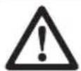
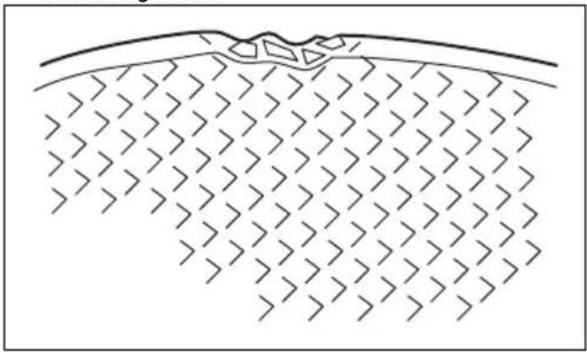
WARNING: Do not use a cutting blade with a rated speed value lower than that of the product. The rated speed value of the cutting blade is marked on the cutting blade, and that of the product is marked on the blade guard.
pie
| Category | Value | |---|---| | 100 m/s | 100 | | XXXX rpm | 100 |Note: Many cutting blades that can be attached to this product are made for stationary saws. The rated speed value of those cutting blades is too low for this product.
CAUTION: Do not use cutting blades with thickness exceeding maximum recommended thickness. Refer to Technical data on page 39.
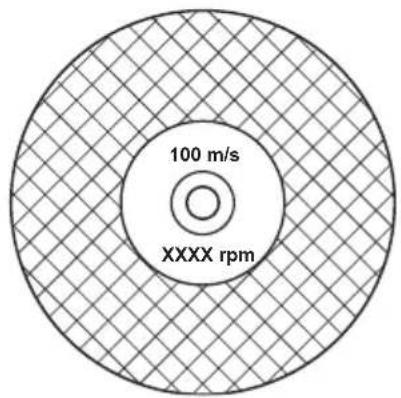
- Cutting blades applicable to this product are available in two basic models; bonded abrasive blades and diamond blades.
natural_image
Technical line drawing of two interlocking gears with no text or symbols- Make sure that the cutting blade has the correct center hole dimension for the installed arbor bushing.
Cutting blade vibration

CAUTION: If you use the product with too much force, the cutting blade can become too hot, bend and cause vibrations. Use the product with less force. If the vibrations continue, replace the cutting blade.
Bonded abrasive cutting blades
WARNING: Do not use bonded abrasive cutting blades together with water. Moisture decreases the strength in the bonded abrasive cutting blade and the cutting blade can break and cause injury.
A bonded abrasive cutting blade is made of small abrasive grains joined with an organic or vitrified bond, molded with fabric reinforcements, which prevents the cutting blade from breaking during high speed operation.
Bonded abrasive cutting blades for different materials
Note: Make sure that you use the correct cutting blades for rail cutting.
| Blade type Material | |
| Concrete blade | Concrete, asphalt, stone masonry, cast iron, aluminum, copper, brass, cables, rubber and plastic. |
| Metal blade Steel | alloy steel and other hard metal. |
| Cutting blade for rail cutting | Rail |
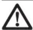
To examine a bonded abrasive cutting blade
• Make sure that there are no cracks or damages on the cutting blade.
natural_image
Diagram of a geological cross-section showing layered strata with no text or symbols- Hang the cutting blade on your finger and hit the cutting blade lightly with a screwdriver. If you do not hear a clear sound, the cutting blade is damaged.
text_image
100 m/s xxxx rpmDiamond blades

WARNING: Diamond blades become very hot when used. A diamond blade that is too hot gives bad performance, blade damage and is a safety risk.

WARNING: Do not use diamond blades to cut plastic material. The hot diamond blade can melt the plastic, which can cause a kickback.
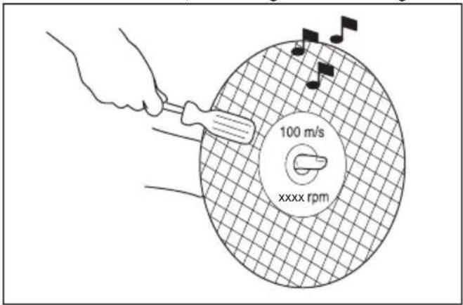
- Diamond blades have a steel core with segments that are made of industrial diamonds.
- Diamond blades are used for masonry, reinforced concrete and stone.
• Make sure that the diamond blade rotates in the direction of the arrows shown on the diamond blade.
natural_image
Circular mechanical gear diagram with evenly spaced teeth and central bore (no text or symbols)• Always use a sharp diamond blade.
- Diamond blades can become blunt if you use an incorrect feeding pressure or when you cut materials such as hard reinforced concrete. If you use a blunt diamond blade it becomes too hot, which can cause the diamond segments to come loose.
To sharpen the cutting blade
Note: For the best cutting results, use a sharp cutting blade.
- To sharpen the cutting blade, cut into soft material, such as sandstone or brick.
Diamond blades for wet cutting
- Diamond blades for wet cutting must be used with water.
- Water decreases the temperature of the cutting blade, increases its service life and decreases dust during operation.
- When wet cutting, collect the waste water safely.
Diamond blades for dry cutting
- For diamond blades for dry cutting it is necessary to have a sufficient airflow around the cutting blade to decrease the temperature. Because of this, diamond blades for dry cutting are recommended only for intermittent operation. After some seconds of operation, it is necessary to let the diamond blade rotate freely, away from the cut. This lets the airflow around the blade decrease the temperature of the diamond blade.
Diamond blade - side clearance
WARNING: Certain cutting situations or poor blades can suffer excessive wear on the side of the segments. Make sure the diamond segment (A) is wider than the blade (B). This is to prevent pinching in the cutting slot and kickback. Refer to Kickback on page 16.
text_image
A B 0
CAUTION: Some cutting situations and worn blades may cause increased wear on the side of the segments. Replace the blade before it is worn out.
To examine the spindle shaft and the flange washers

CAUTION: Use only HUSQVARNA flange washers with a minimum diameter of 105 mm/4.1 in.
WARNING: Do not use defective, worn or dirty flange washers. Use only flange washers of the same dimension. Incorrect flange washers can cause the cutting blade to become damaged or come loose.
Examine the spindle shaft and the flange washers when you replace the cutting blade.
- Make sure that the threads on the spindle shaft are not damaged. Replace damaged parts.
natural_image
Diagram of a mechanical component with two circular parts and directional arrows indicating motion (no text or symbols)-
Make sure that the areas of contact on the cutting blade and the flange washers are not damaged. Replace damaged parts.
-
Make sure that the flange washers are clean and of the correct dimension.
-
Make sure that the flange washers move freely on the spindle shaft.
To do a check of the arbor bushing
The arbor bushings are used to attach the product to the center hole of the cutting blade. The product is supplied with one of these two types of arbor bushings:
- An arbor bushing that can be turned to the other side and be applicable for 20 mm/0.79 in. or 25.4 mm/1 in. center holes.
• A 25.4 mm/1 in. arbor bushing. - A decal on the blade guard shows installed arbor bushing and specification for applicable cutting blades.
natural_image
Simple line drawing of a globe with a downward arrow and partial geometric shapes (no text or symbols)• Make sure that the dimension of the center hole of the cutting blade agrees with the installed arbor bushing. The diameter of the center hole is printed on the cutting blade.
- Use only HUSQVARNA arbor bushings.
To examine the direction of rotation of the cutting blade
- Find the arrows on the rear belt guard that show the direction of rotation of the spindle shaft.
text_image
Technical diagram illustrating gear meshing process with labeled components and directional arrows- Find the arrow on the cutting blade that shows the direction of rotation of the cutting blade.
- Make sure that the direction arrows of the cutting blade and the spindle shaft have the same direction.
To install the cutting blade

WARNING: Make sure that the engine is off and that the stop switch is in the STOP position.

WARNING: Always use protective gloves when you assemble the product.
- Examine the flange washers and the spindle shaft. Refer to To examine the spindle shaft and the flange washers on page 14.
- Push back and hold the SmartGuard in the retracted position.
natural_image
Diagram of a mechanical device with rotating components and directional arrows (no text or symbols)Note: This step only applies to K 1270 SmartGuard.
- Put the cutting blade on the arbor bushing (A) between the inner flange washer (B) and the flange washer (C). Turn the flange washer until it holds on to the shaft.
text_image
Diagram of a biological structure with labeled parts A, B, and C, likely illustrating a developmental or anatomical process.- Put a tool into the hole in the front belt guard and turn the cutting blade until the shaft is locked.
natural_image
Line drawing of a mechanical device with no visible text or symbols- Tighten the cutting blade bolt to 25 Nm/18.5 ft-lb.
natural_image
Technical line drawing of a mechanical tool or cutting machine (no text or symbols present)To reverse the cutting head (K 1270 II)
WARNING: Only cut with the cutting head reversed if a standard procedure is not possible.
The product has a reversible cutting head that lets you cut near a wall or at ground level. Only cut with the cutting head reversed if a standard procedure is not possible. If a kickback occurs, it is more difficult to control the product if the cutting head is reversed. The distance between the cutting blade and the center of the product is longer, which means that the handle and the cutting blade do not align. This has a negative effect on the balance in the product and it is more difficult to hold the product if the cutting blade is pinched or stalled in the kickback zone. Refer to Kickback on page 16.

WARNING: Make sure that the engine is off and that the stop switch is in the STOP position.

WARNING: Always use protective gloves when you assemble the product.
- Remove the cutting blade, the front belt cover and the cutting head. Refer to steps 1-5 in To replace the drive belt on page 29.
- Remove the 2 screws and nuts that hold the spray nozzle.
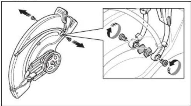
natural_image
Technical diagram showing mechanical assembly with arrows indicating motion, including a close-up inset of hands holding fasteners (no text or symbols present)- Remove the 2 screws from the adjustment handle for the blade guard.
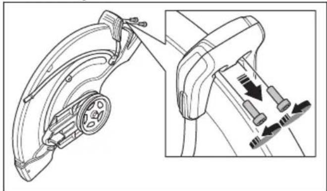
natural_image
Technical line drawing of a mechanical device with internal components and directional arrows indicating motion (no text or symbols)- Remove the adjustment handle for the blade guard
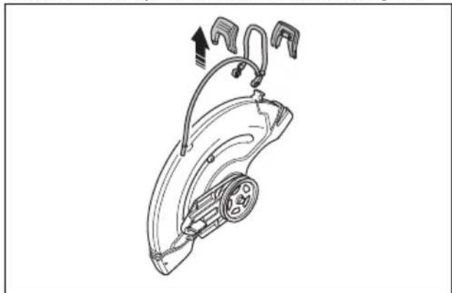
natural_image
Technical line drawing of a mechanical device with attached clamps and a central hub (no text or symbols)- Remove the stop sleeve.
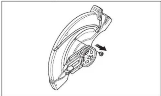
natural_image
Technical line drawing of a mechanical component with no visible text or symbols- Move the bearing housing and install the stop sleeve.
natural_image
Mechanical component diagram showing a rotating wheel and housing mechanism (no text or symbols)-
Install the stop sleeve.
-
Install the drive belt on the opposite side.
natural_image
Mechanical assembly diagram showing a wheel and bracket assembly with directional arrows (no text or labels)-
Install the cutting head and the drive belt cover, refer to To replace the drive belt on page 29.
-
Install the spray nozzle and the cutting blade in the opposite sequence to how they were removed.
Operation
Introduction

WARNING: Read and understand the safety chapter before you use the product.
Kickback
WARNING: Kickbacks are sudden and can be very violent. The power cutter can be thrown up and back towards the user in a rotating motion causing serious or even fatal injury. It is vital to understand what causes
kickback and how to avoid it before using the product.
Kickback is the sudden upward motion that can occur if the blade is pinched or stalled in the kickback zone. Most kickbacks are small and pose little danger. However a kickback can also be very violent and throw the power cutter up and back towards the user in a rotating motion causing serious or even fatal injury.
Reactive force
A reactive force is always present when cutting. The force pulls the product in the opposite direction to the blade rotation. Most of the time this force is insignificant.
If the blade is pinched or stalled, the reactive force will be strong and you might not be able to control the power cutter.
natural_image
Diagram showing a mechanical component interacting with a circular object, with directional arrows indicating motion (no text or symbols)Never move the product when the cutting equipment is rotating. Gyroscopic forces can obstruct the intended movement
Kickback zone
Never use the kickback zone of the blade for cutting. If the blade is pinched or stalled in the kickback zone, the reactive force will push the power cutter up and back towards the user in a rotating motion causing serious or even fatal injury.
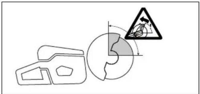
text_image
Diagram illustrating safety hazard with a warning sign and circular hazard symbol, likely from an emergency or hazard context.Rotational kickback
A rotational kickback occurs when the cutting blade does not move freely in the kickback zone.
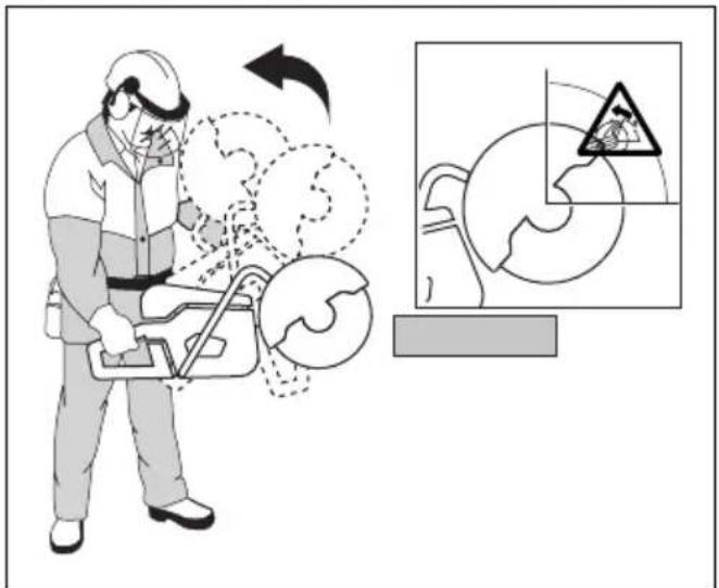
text_image
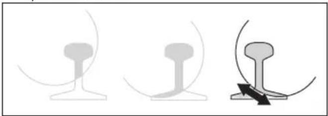
Safety instruction illustration showing a worker using a tool to clean air, with an inset diagram illustrating hazard zones.Climbing kickback
If the kickback zone is used for cutting, the reactive force drives the blade to climb up in the cut. Do not use the kickback zone. Use the lower quadrant of the blade to avoid climbing kickback.
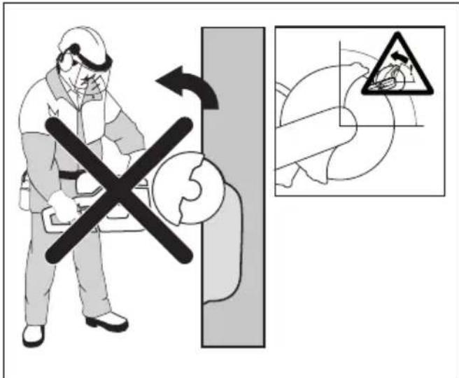
text_image
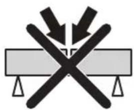
Safety warning illustration showing a worker using a tool to switch over a gear, with an inset showing a hazard symbol.Pinching kickback
Pinching is when the cut closes and pinches the blade. If the blade is pinched or stalled the reactive force will be strong and you might not be able to control the power cutter.
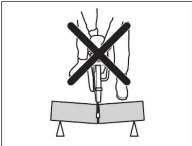
natural_image
Diagram of a medical procedure with a surgical tool and X-shaped cross symbol above a rectangular block (no text or labels)If the blade is pinched or stalled in the kickback zone, the reactive force will push the power cutter up and back towards the user in a rotating motion causing serious or even fatal injury. Be alert for potential movement of the work piece. If the work piece is not properly supported and shifts as you cut, it might pinch the blade and cause a kick back.
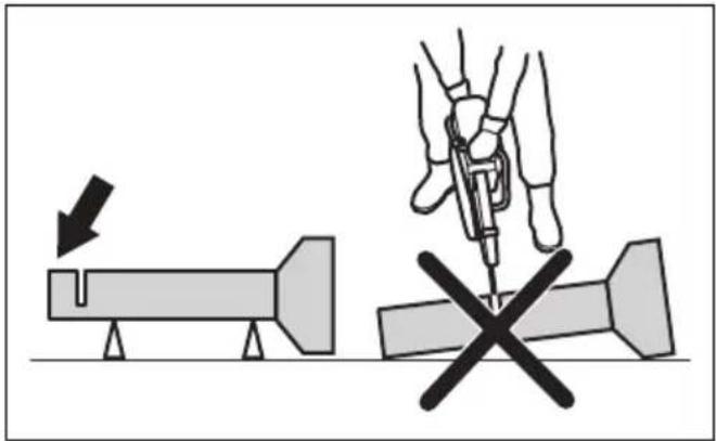
Pipe cutting
Special care should be taken when cutting in pipes. If the pipe is not properly supported and the cut kept open throughout the cutting, the blade might be pinched. Be especially alert when cutting a pipe with a belled end or
a pipe in a trench that, if not properly supported, may sag and pinch the blade.
If the pipe is allowed to sag and close the cut, the blade will be pinched in the kick back zone and a severe kick back might develop. If the pipe is properly supported, the end of the pipe will move downward, the cut will open and no pinching will occur.
Secure the pipe so it does not move or roll during cutting. Make sure that the cut opens to avoid pinching the blade.
text_image
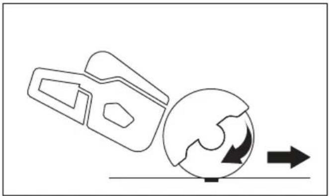
Diagram illustrating a mechanical or robotic operation with labeled components and directional arrows indicating movement.To cut in smaller pipes

WARNING: If the blade is pinched in the kickback zone, it will cause a severe kickback.
If the pipe is smaller than the maximum cutting depth of the product, the cutting operation can be done in 1 step from top to bottom.
- Cut the pipe from top to bottom.
natural_image
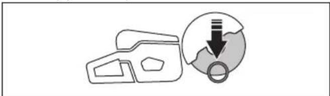
Simple line drawing of a device and a circular diagram with a downward arrow (no text or symbols)To cut in larger pipes

WARNING: If the blade is pinched in the kickback zone it will cause a severe kickback.
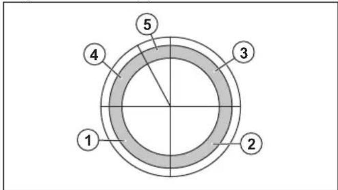
If the pipe is larger than the maximum cutting depth of the product, and can not be rolled, the cutting operation needs to be divided in 5 steps.
- Divide the pipe into 5 sections. Do a mark of those sections and of a cutting line. Cut a shallow guide groove around the pipe.
text_image
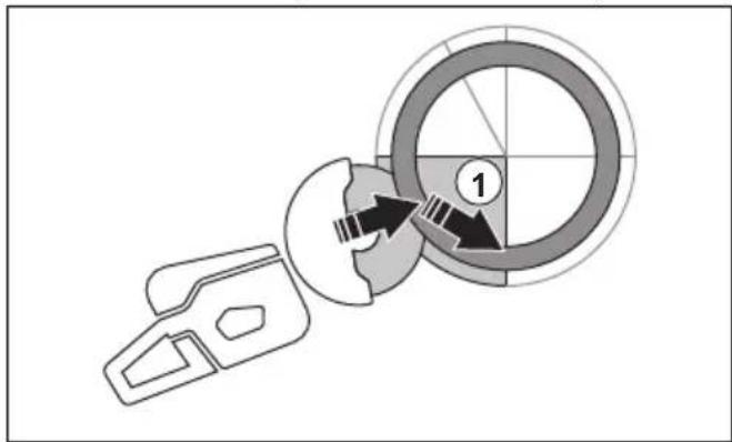
1 2 3 4 5- Cut those sections in 5 steps with the cutting directions shown by the arrows in each step.
natural_image
Diagram showing a mechanical component with a circular target and directional arrow, no text or symbols present.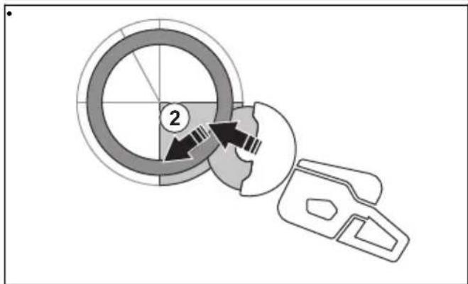
text_image
Diagram showing a circular component with labeled parts and directional arrows, likely illustrating a mechanical or electrical process.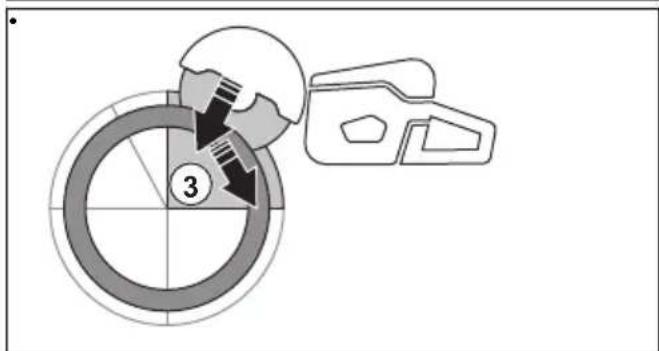
text_image
③
text_image
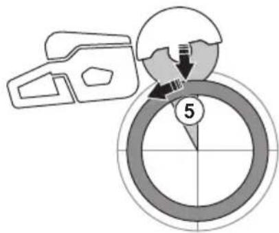
Diagram showing a mechanical assembly with labeled component '4' and directional arrows indicating motion or movement.- Make the final separating cut from the top of the pipe pulling backwards, without involving the upper quadrant of the blade. Adjust the blade guard to full forward position for maximum protection.
text_image
5
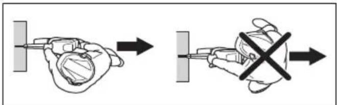
WARNING: If the pipe is properly supported, it should not pinch the blade when separated in section 5. However be alert if the blade is pinched during the final separation. If the blade is pinched in the lower section, the product may pull forward away from the operator, rather then resulting in a rotating kickback.
To prevent a kickback

WARNING: Avoid situations where there is a risk of kickback. Take care when using your power cutter and make sure that the blade is never pinched in the kickback zone.

WARNING: Be careful when you put the blade in an existing cut.

WARNING: Make sure that the work piece cannot move during a cutting operation.
WARNING: Only you and proper working technique can eliminate kickback and its dangers.
• Always support the work of piece so that the cut can keep open when cutting through. When the cut is open there is no kickback. If the cut is closed and pinches the blade, there is a risk of kickback.
natural_image
Symbolic illustration of crossed-out black-and-white lines crossing over a gray rectangular block, with no text or symbols present.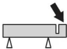
natural_image
Simple diagram of a beam with supports and a downward arrow indicating force or direction (no text or symbols)Basic working techniques
WARNING: Do not pull the product to one side. This can prevent the free movement of the cutting blade. The cutting blade can break and cause injury to the operator or bystanders.

WARNING: Do not grind with the side of the cutting blade. The cutting blade can break and cause injury to the operator or bystanders. Only use the cutting edge.

WARNING: Make sure that the cutting blade is installed correctly and does not show signs of damage.

WARNING: Before cutting in an existing cut made by a different blade, make a sure that the slot is not thinner than your blade as that can result in binding in the cutting slot and a kickback.

WARNING: Cutting metal generates sparks that can cause fire. Do not use the product near flammable material or gases.
- The product is made to cut with bonded abrasive cutting blades or diamond blades made for high speed handheld product. The product must not be used with other types of blade, or for other types of operation.
- Do a check that the correct cutting blade is used for the material to be cut. Refer to Applicable cutting blades on page 12 for instructions.
- Do not cut asbestos materials.
- Keep a safe distance from the cutting blade when the engine is on. Do not try to stop a rotating blade with a part of your body. To touch a rotating blade, although the engine is off, can result in serious injury or death.
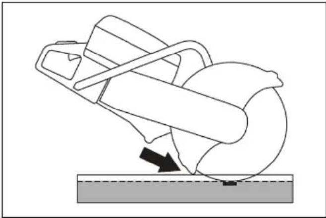
• The cutting blade continues to rotate for a while after the throttle trigger is released. Make sure that the
cutting blade has stopped before the product is moved or put down. If it is necessary to stop the cutting blade quickly, let the cutting blade lightly touch a hard surface.
- Do not move the product with the engine on.
- Hold the product with 2 hands. Hold the product tightly with thumbs and fingers fully around the plastic handles with insulation. The right hand must be on the rear handle and the left hand on the front handle. All operators must use this hold. Do not operate a power cutter with only 1 hand.
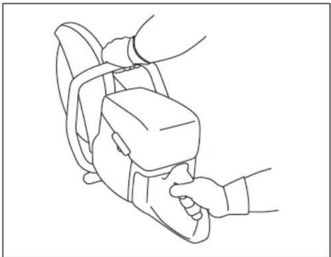
natural_image
Line drawing of a person using a handheld device to interact with another person (no text or symbols present)- Stand parallel to the cutting blade. Avoid standing straight behind. If a kickback occur, the saw will move in the plane of the cutting blade.
text_image
Diagram illustrating a hand holding a device before and after disassembly, with a cross symbol indicating disassembly.- Do not go away from the product with the engine on. Before you go away from the product, stop the engine and make sure that there is no risk of accidental start.
- Use the adjustment handle of the blade guard to adjust the rear section of the guard flush with the work piece. Spatter and sparks from the cut material are then collected up by the guard and led away from the operator. The guards for the cutting
equipment must always be installed when the product is on.
natural_image
Diagram of a mechanical device with a rotating shaft and base, showing motion direction (no text or symbols)- Do not use the kickback zone of the blade for cutting. Refer to Kickback zone on page 17 for instructions.
- Do not operate the product before the work area is clear and your feet and body are in a stable position.
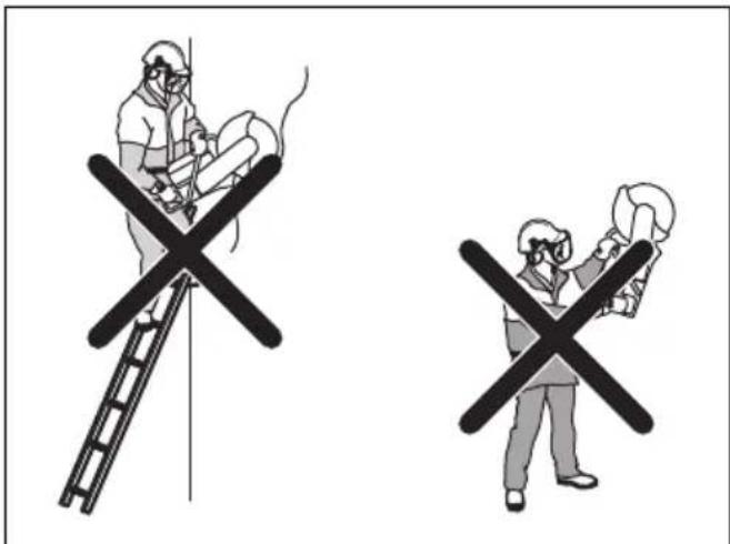
- Do not cut above shoulder height.
- Do not cut from a ladder. Use a platform or scaffold if the cut is above shoulder height. Do not overreach.
text_image
Safety warning illustration showing two workers using a ladder to smoke or fire, with one crossed out and the other holding a helmet.- Stay at a comfortable distance from the work piece.
• Make sure that the cutting blade can move freely when the engine is started. - Apply the cutting blade carefully with high rotating speed (full throttle). Keep full speed until cutting is complete.
- Let the product do the work. Do not push the cutting blade.
- Feed the product down in line with the blade. Pressure from the side can cause damage to the blade and is very dangerous.
natural_image
Line drawing of a person using a handheld device to lift or lift an object, no text or symbols present- Move the blade slowly forward and rearward to get a small contact area between the blade and the material to be cut. This decreases the temperature of the blade and is an effective way to cut.
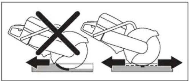
natural_image
Diagram showing two mechanical components with a crossed-out black X mark, no text or symbols presentBasic working techniques with K 1270 SmartGuard
WARNING: The SmartGuard function is disengaged if the SmartGuard is manually retracted. Only retract the SmartGuard manually if you must and there are no risks of kickback.
SmartGuard gives more coverage of the blade. This decreases the risk that you touch the blade if a kickback occurs.
- You can retract the SmartGuard manually with the SmartGuard handle.
- Hold the SmartGuard handle with a left hand finger while the remaining fingers hold the front handle at the same time.
natural_image
Line drawing of a person using a power saw to cut a saw (no text or symbols present)To decrease dust during operation
The product has a wet cutting kit to decrease harmful dust in the air during operation. The wet cutting kit has low water consumption.
- When possible, use wet cutting blades with water cooling. Refer to Cutting blades on page 11.
- Adjust the water flow with the valve. The correct flow is different for different types of tasks.
- Make sure that the water pressure is correct. Refer to Technical data on page 39. If the water hose comes off at the supply source, the supplied water pressure can be too high.
Fuel
This product has a two-stroke engine.

CAUTION: Incorrect type of fuel can result in engine damage. Use a mixture of gasoline and two-stroke oil.
Two-stroke oil
- For best results and performance use HUSQVARNA two-stroke oil.
- If HUSQVARNA two-stroke oil is not available, use a two-stroke oil of good quality for air-cooled engines. Speak to your servicing dealer to select the correct oil.

CAUTION: Do not use two-stroke oil for water-cooled outboard engines, also referred to as outboard oil. Do not use oil for four-stroke engines.
Premixed fuel
- Use HUSQVARNA premixed alkylate fuel for best performance and extension of the engine life. This fuel contains less harmful chemicals compared to regular fuel, which decreases harmful exhaust fumes. The quantity of remains after combustion is
lower with this fuel, which keeps the components of the engine more clean.
To mix gasoline and two-stroke oil
| Gasoline, liter Two-stroke oil, | liter |
| 2% (50:1) | |
| 5 0.10 | |
| 10 0.20 | |
| 15 0.30 | |
| 20 0.40 | |
| US gallon US fl. oz. | |
| 1 2 12 | |
| 2 1/2 6 12 | |
| 5 12 78 |
CAUTION: Small errors can influence the ratio of the mixture drastically when you mix small quantities of fuel. Measure the quantity of oil carefully and make sure that you get the correct mixture.
text_image
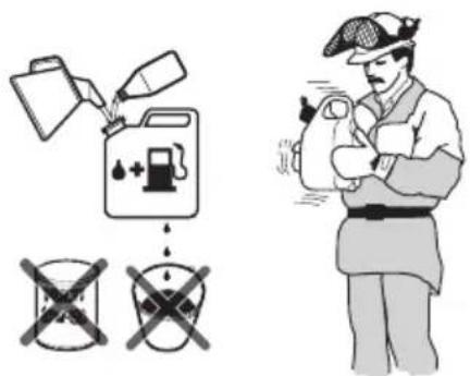
Safety warning illustration showing fuel injection and cross symbol with a person holding a bottle- Fill half the quantity of gasoline in a clean container for fuel.
- Add the full quantity of oil.
- Shake the fuel mixture.
- Add the remaining quantity of gasoline to the container.
- Carefully shake the fuel mixture.
CAUTION: Do not mix fuel for more than 1 month at a time.
To fill fuel

CAUTION: Do not use gasoline with an octane number less than 90 RON (87 AKI). It causes damage to the product.

CAUTION: Do not use gasoline with more than 10% ethanol concentration (E10). It causes damage to the product.
Note: Carburetor adjustment is in some conditions necessary when you change the type of fuel.
- Use gasoline with a higher octane number if you frequently use the product at continuously high engine speed.
- Open the fuel tank cap slowly to release the pressure.
- Fill slowly with a fuel can. If you spill fuel, remove it with a cloth and let the remaining fuel dry off.
- Clean the area around the fuel tank cap.
- Tighten the fuel tank cap fully. If the fuel tank cap is not tightened, there is a risk of fire.
- Move the product a minimum of 3 m (10 ft) from the position where you filled the tank before a start.
To start the product with a cold engine
text_image
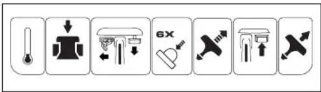
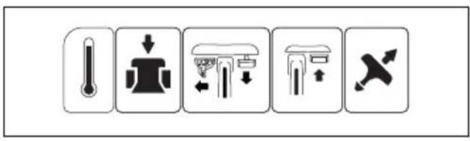
Row of eight black-and-white icons representing various industrial or mechanical components, including thermometer, valve, 6X valve, hammer, pump, and directional arrows.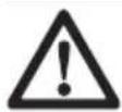
WARNING: Make sure that the cutting blade can rotate freely. It starts to rotate when the engine starts.
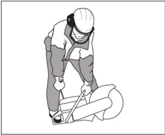
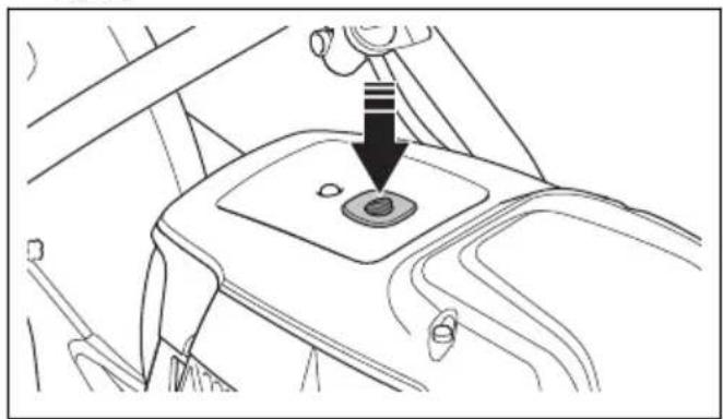
- Push the decompression valve to decrease the pressure in the cylinder. The decompression valve goes back to its initial position when the product starts.
natural_image
Line drawing of a car gear shift lever with a downward arrow indicating motion (no text or symbols)- Make sure that the STOP switch is in the left position.

text_image
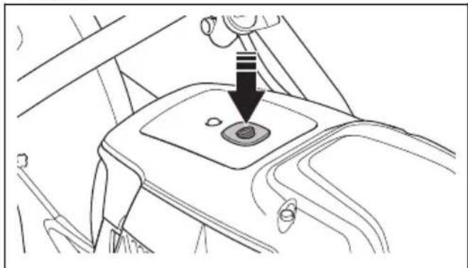
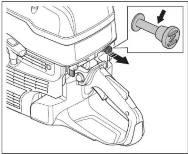
STOP- Pull the choke control fully to get the start throttle position.
natural_image
Technical line drawing of a mechanical component with an inset showing a pin assembly (no text or symbols present)- Push the air purge bulb 6 times until it is fully filled with fuel.
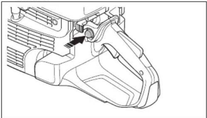
natural_image
Technical line drawing of a mechanical component with no visible text or symbols-
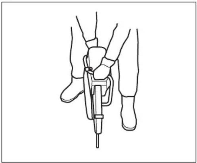
Hold the front handle with your left hand.
-
Put your right foot on the lower section of the rear handle to push the product against the ground.
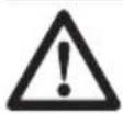
WARNING: Do not wind the starter rope around your hand.
- Pull the starter rope slowly with your right hand until you feel a resistance as the starter pawls engage. Then pull continuously and quickly.
natural_image
Illustration of a worker in safety gear using a tool on a circular object (no text or symbols)
CAUTION: Do not pull the starter rope fully and do not let go of the starter rope handle when the starter rope is extended. This can cause damage to the product.
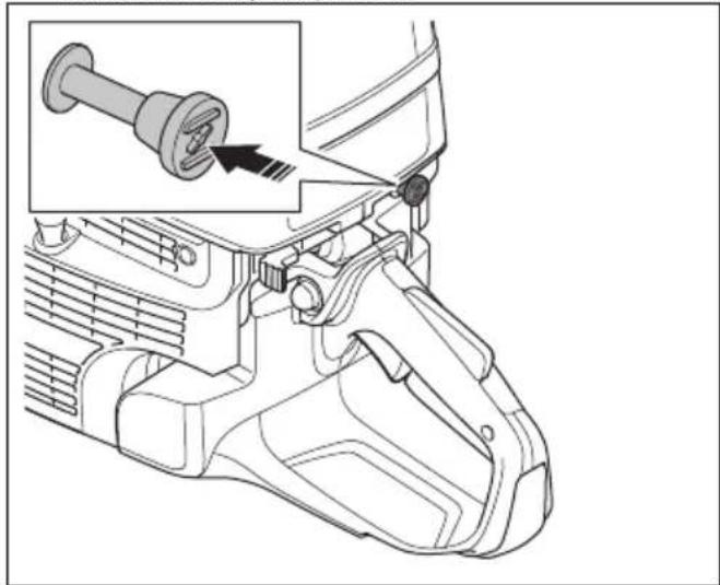
- Push the choke control when the engine starts. If the choke is pulled out, the engine will stop after some seconds. If the engine stops, pull the starter rope handle again.
natural_image
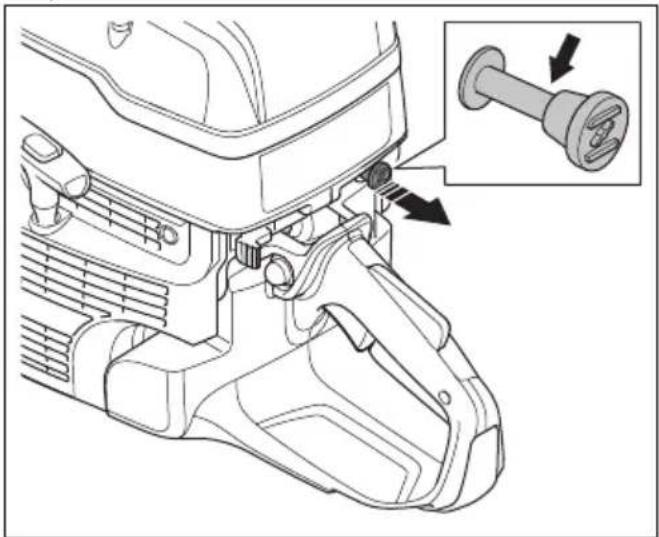
Technical line drawing of a mechanical component with an inset showing a pin inserted into a housing (no text or symbols present)- Push the throttle trigger to disengage the start throttle and set the product at idle speed.
natural_image
Technical line drawing of a mechanical component with directional arrows indicating movement or assembly (no text or symbols present)To start the product with a warm engine
text_image
Diagram showing five different weather and heating symbols with corresponding icons and labels
WARNING: Make sure that the cutting blade can rotate freely. It starts to rotate when the engine starts.
- Push the decompression valve to decrease the pressure in the cylinder. The decompression valve goes back to its initial position when the product starts.
natural_image
Mechanical gear shift lever diagram showing a downward force application on the intake tray (no text or symbols present)- Make sure that the STOP switch is in the left position.

text_image
STOP- Pull the choke control fully to get the start throttle position.
natural_image
Technical line drawing of a mechanical component with an inset showing a pin assembly (no text or symbols present)- Push the choke control to disable the choke. The start throttle stays in position.
natural_image
Technical line drawing of a mechanical component with an inset showing a pin inserted into a housing (no text or symbols present)- Hold the front handle with your left hand.
- Put your right foot on the lower section of the rear handle to push the product against the ground.
WARNING: Do not wind the starter rope around your hand.
- Pull the starter rope slowly until you feel a resistance as the starter pawls engage. Then pull continuously and quickly.
natural_image
Illustration of a worker in safety gear performing manual labor on a large object (no text or symbols visible)
CAUTION: Do not pull the starter rope fully and do not let go of the starter rope handle when the starter rope is extended. This can cause damage to the product.
- Push the throttle trigger to disengage the start throttle and set the product at idle speed.
natural_image
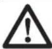
Technical line drawing of a mechanical component with directional arrows indicating movement or force (no text or symbols present)To stop the product

WARNING: The cutting blade continues to rotate for a while after the engine stops. Make sure that the cutting blade can rotate freely until it fully stops. If it is necessary to stop the cutting blade quickly, let the cutting blade lightly touch a hard surface. Risk of serious injury.
- Move the STOP switch to the right to stop the engine.
text_image
Technical diagram showing a mechanical component with an inset highlighting a stop button labeled 'STOP'Rail cutting (K 1270 II Rail)
General

CAUTION: Do not install the rail fixture on the product during transport or when you move the product. When the product and the rail fixture are put together, there is a larger risk of damage than when they are disconnected. Damages, such as bent parts, can result in less accurate cuts.
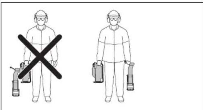
text_image
Safety warning illustration showing two workers in protective gear holding fire extinguishers, with one crossed out by a black X symbol.To install the rail fixture

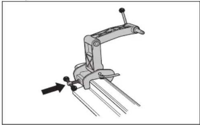
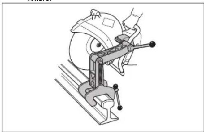
CAUTION: Install the rail fixture to the rail before you install the product to the rail fixture. There is a risk that the rail fixture is not installed at a correct angle if the product is installed first.
- Attach the rail fixture to the rail. Tighten the handle fully.
natural_image
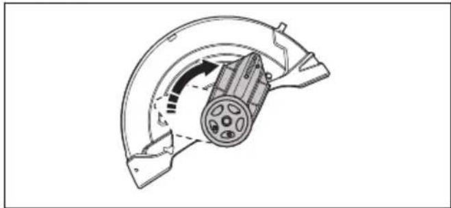
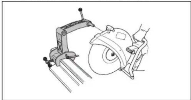
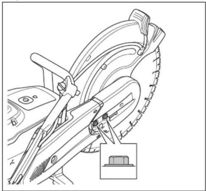
Mechanical clamp device with lever mechanism and directional arrow (no text or symbols)- Install the product on the rail fixture with the right side of the product against the rail fixture.
natural_image
Technical line drawing of a mechanical device with a circular component and lever mechanism (no text or symbols)Note: It is also possible to install the product with the left side against the rail fixture, but we recommend to use the right side when possible.
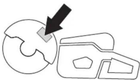
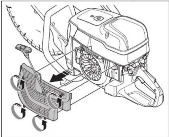
To prepare the cutting guide
Note: The first time you use the rail system, you must cut the cutting guide.
The cutting guide helps the operator to put the cutting blade in correct position for the cut.
- Fold out the cutting guide.
- Put the cutting guide parallel to the rail.
natural_image
Technical line drawing of a cutting machine with a blade and tool, showing no text or symbols- Carefully cut off the cutting guide.
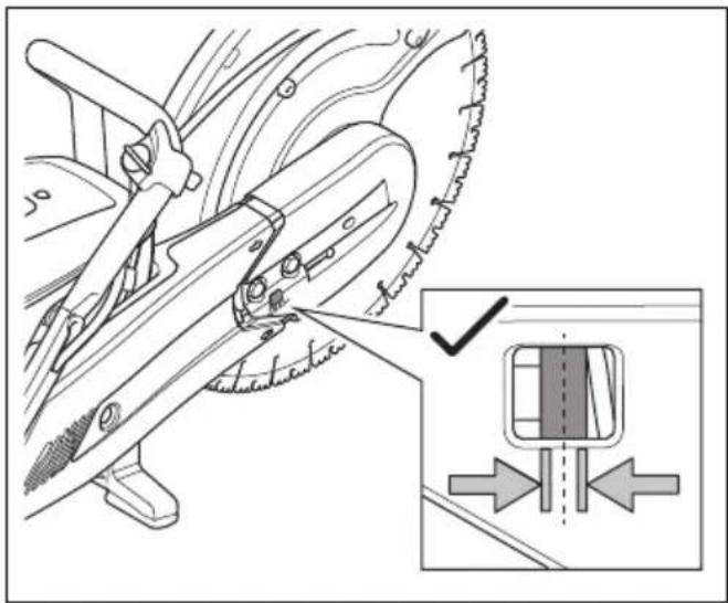
To use the rail fixture
- Fold out the cutting guide.
-
Align the saw cut and fold in the cutting guide.
-
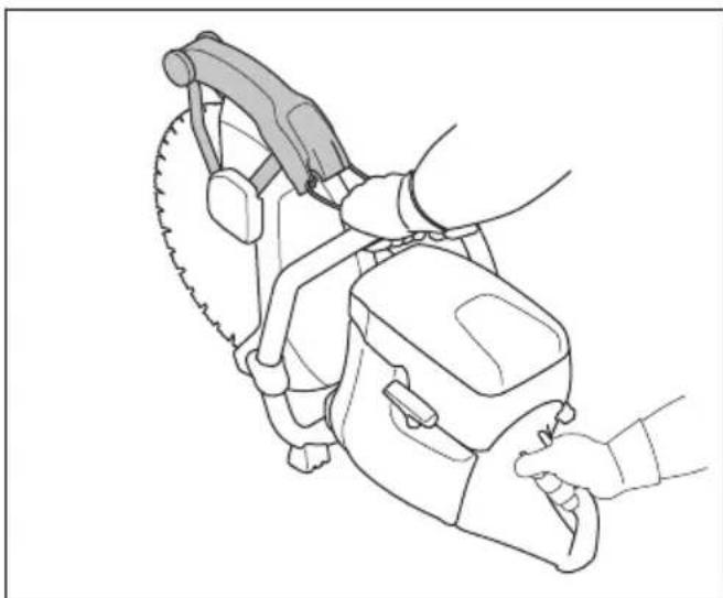
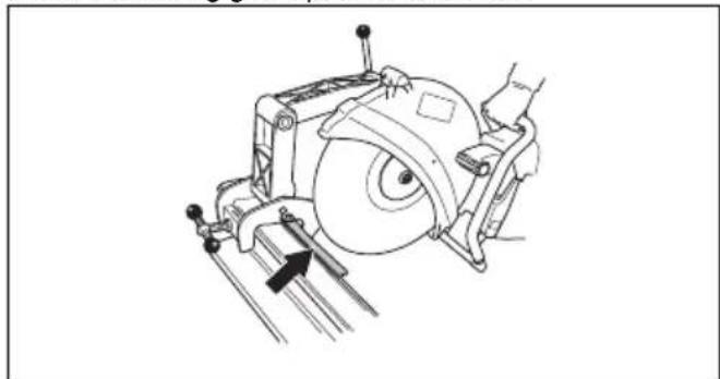
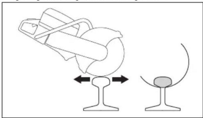
Move the product rearward and forward to decrease the contact surface between the cutting blade and the rail. More contact surface increases the risk of glazing the cutting blade or making it blunt.
natural_image
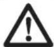
Diagram showing a mechanical device with a curved handle and a circular component, both mounted on a stand (no text or symbols present)- Cut the rail.
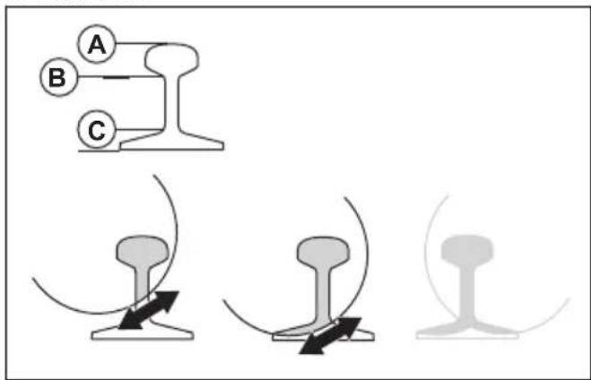
text_image
Diagram illustrating rail track joint movements with labeled points A, B, and C, showing structural changes and motion direction.a) Cut through the section at the top (A).
b) Cut through the section in the middle (B).
c) Cut through the section in the bottom (C).
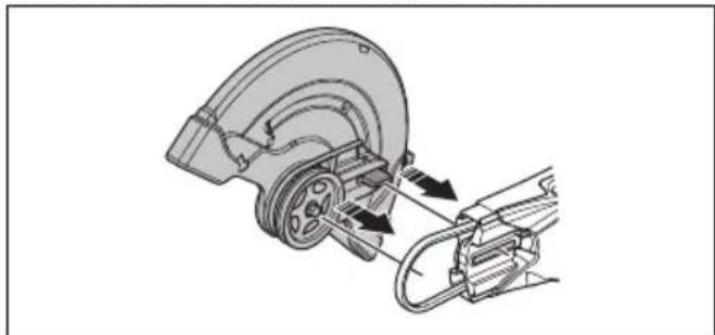
- If the cut cannot be completed from 1 side, the product must be turned around.
a) Stop the product. Refer to To stop the product on page 25.
b) Remove the product from the rail fixture.
c) Install the product with its left side to the rail fixture.
natural_image
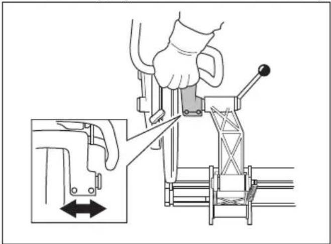
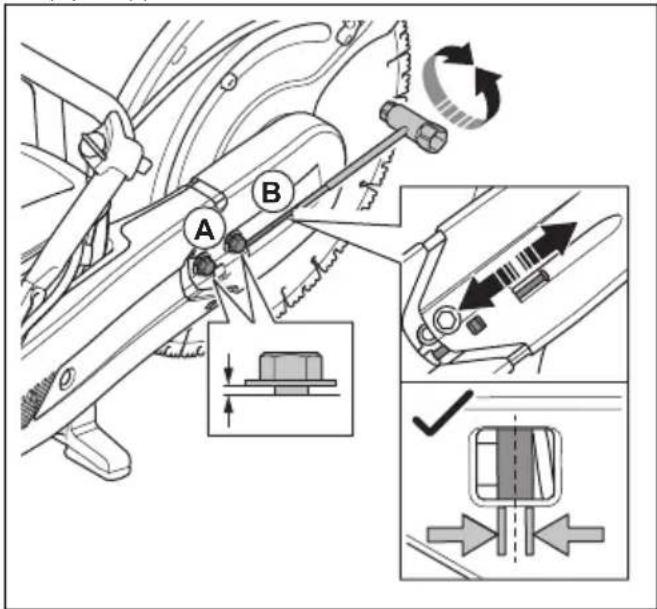
Technical line drawing of a mechanical clamp or bracket assembly (no text or symbols)d) Put the cutting blade against the rail and make sure that it is in the center of the cut. If it is necessary, adjust the fixture attachment bushing.
natural_image
Technical illustration of a mechanical device with a hand operating a lever, showing internal components and a close-up view of the lever mechanism (no text or symbols present)e) Continue to cut.
natural_image
Three abstract diagrams showing different mechanical or structural configurations, with no visible text or symbols.-
Complete the cut.
-
Stop the product.
-
Remove the product from the rail fixture.
-
Remove the rail fixture from the rail.
To cut rail, recommendations
Note: With correct cutting technique, the time to cut a 50 kg/m rail is 1 minute and to cut 60 kg/m rail is 1.5 minute. If more time is necessary, do a check of the cutting technique and the cutting blades. Incorrect cutting technique causes problems, such as cuts that are not accurate. An incorrect, blunt or worn cutting blade can also cause cuts that are not accurate.
-
To get accurate cuts, only use high quality cutting blades that are made specially to cut rail.
• To make straight cuts, start with these steps: -
Apply full throttle until the blade is at full speed.
- Decrease the throttle and keep it below the speed limit until the cutting blade is stable with no vibrations.
- Start to cut.
- Apply full throttle and keep full speed until the cut is completed.
- Hold the product handle with your hands aligned with the cutting blade. This gives a straight cut and decreases the wear on the cutting blade.
- For the best result and a straight cut, install the power cutter with its right side to the fixture.
Maintenance
Introduction

WARNING: Read and understand the safety chapter before you do maintenance on the product.
For all servicing and repair work on the product, special training is necessary. We guarantee that professional repairs and servicing is available. If your dealer is not a
service agent, speak to them for information about the nearest service agent.
For spare parts, speak to your HUSQVARNA dealer or service agent.
Maintenance schedule
The maintenance schedule shows the necessary maintenance of the product. The intervals are calculated on daily use of the product.
* Refer to Safety devices on the product on page 8.
** Refer to Cutting blades on page 11.
| Daily Weekly Monthly Yearly | ||||
| Clean External cleaning | Spark plug | |||
| Cold air intake Fuel tank | ||||
| Function inspection | General inspection Vibration damping system* Fuel system | |||
| Fuel leaks Muffler* Air filter | ||||
| Water delivery system Drive belt Clutch | ||||
| Throttle lockout* Carburetor | ||||
| Stop switch* Starter housing | ||||
| Blade guard and SmartGuard* | ||||
| Cutting blade** | ||||
| Replace Fuel filter | ||||
| * Refer to Safety devices on the product on page 8. ** Refer to Cutting blades on page 11. | ||||
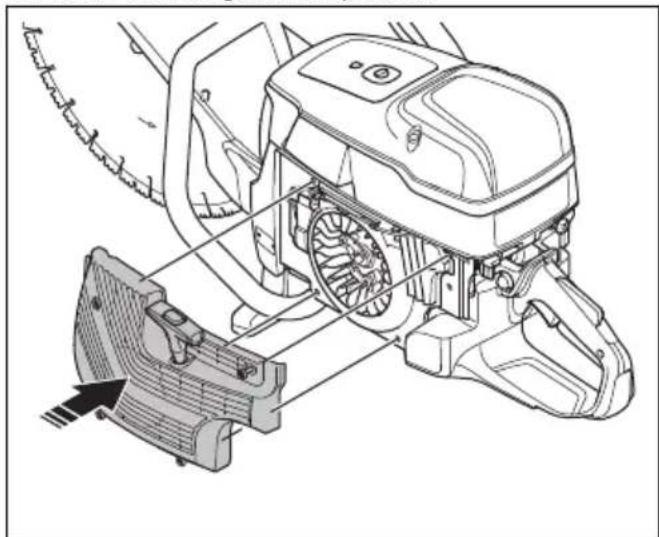
To clean externally
- Flush the product externally with clean water after each day of operation. If it is necessary, use a brush.
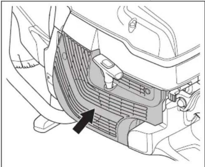
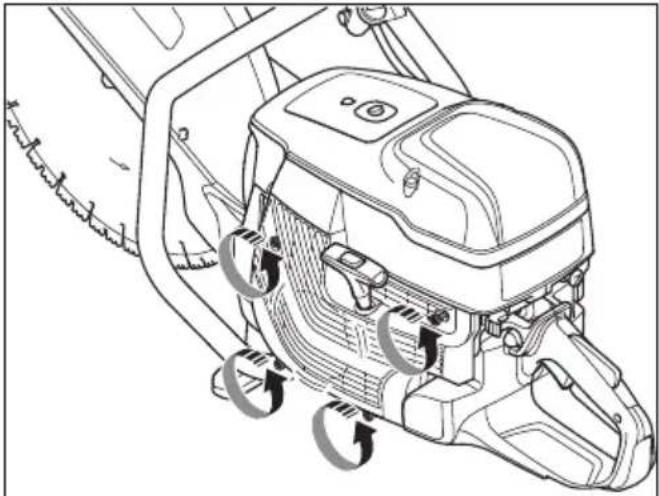
To clean the cold air intake
Note: A dirty or blocked air intake makes the product too hot. This can cause damage to the piston and cylinder.
- Clean the cold air intake if it is necessary.
natural_image
Technical diagram of a car air vent assembly with no visible text or symbols- Remove blockage, dirt and dust with a brush.
To examine the spark plug
Note: Always use the recommended spark plug type. Use of the incorrect spark plug can cause damage to the piston and cylinder. For recommended spark plug refer to Technical data on page 39.
Examine the spark plug if the product is low on power, does not start easily or if it operates unsatisfactorily at idle speed.
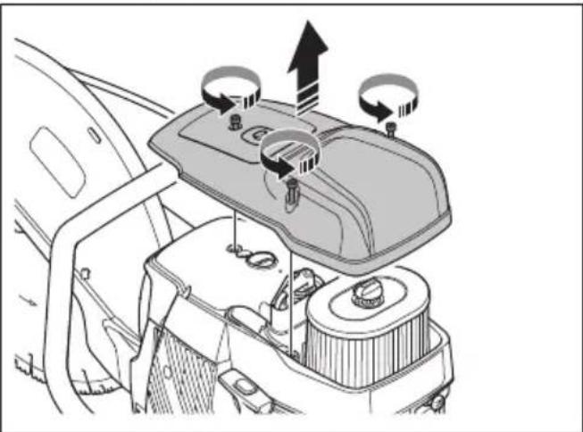
- Loosen the 3 screws on the air filter cover and remove the air filter cover.
natural_image
Diagram of a car interior showing dashboard, intake manifold, and battery compartment with directional arrows (no text or symbols)- Make sure that the spark plug cap and ignition cable are not damaged to prevent the risk of electrical shock.
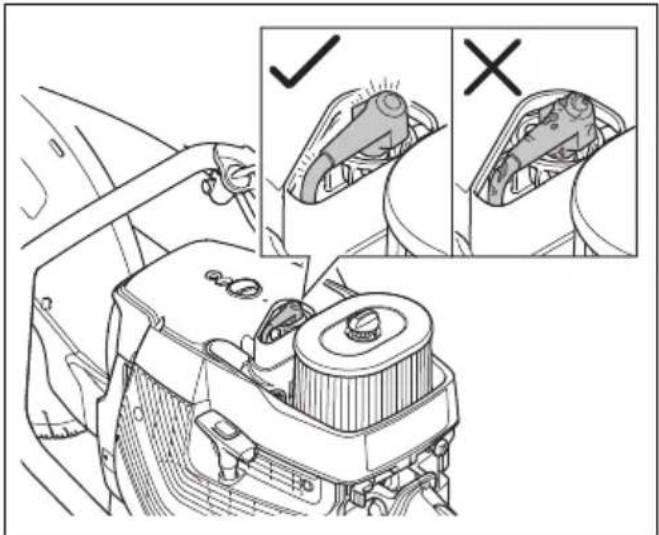
text_image
Diagram illustrating car interior cleaning steps with check and cross icons for inspection and repair actions- Clean the spark plug if it is dirty.
- Make sure that the electrode gap is 0.5 mm.
- If it is necessary, replace the spark plug.
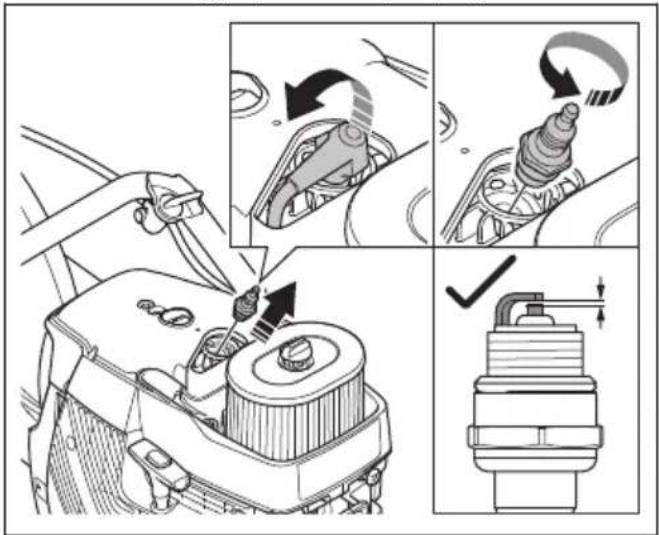
text_image
Technical diagram illustrating engine tool path and valve mechanism with labeled steps and component illustrationsTo do a general inspection
- Make sure that all nuts and screws on the product are tightened correctly.
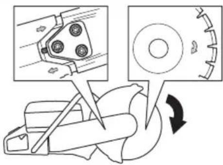
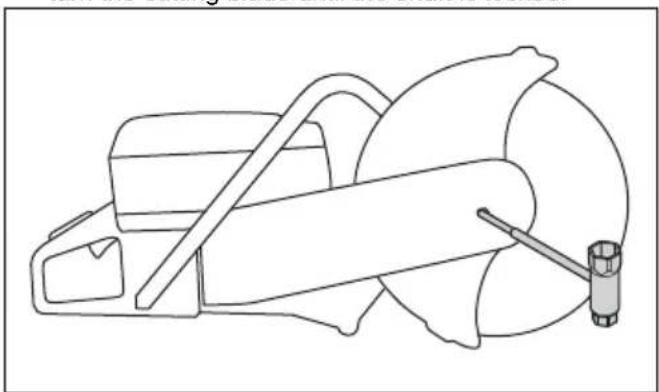
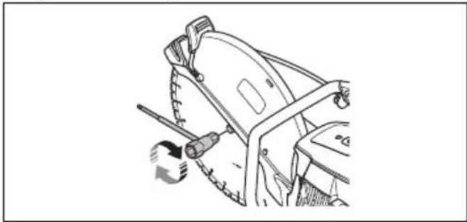
To replace the drive belt

WARNING: Do not start the product without all guards and covers installed.
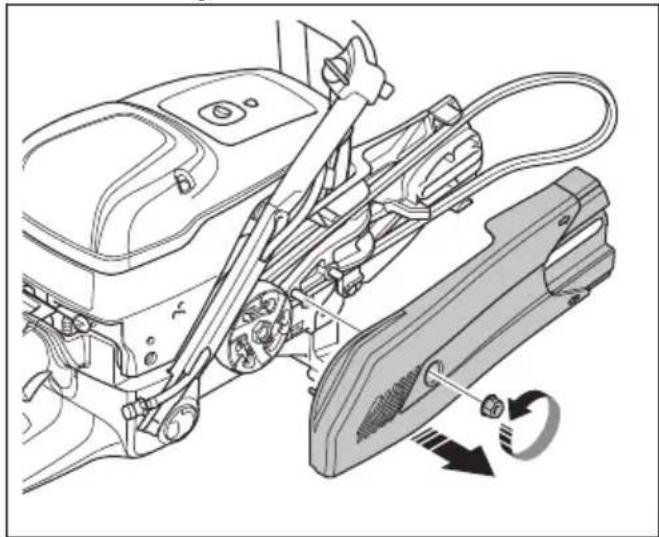
- Turn the bolt for the cutting blade counterclockwise with a wrench to remove the cutting blade.
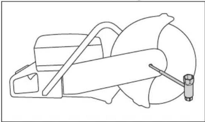
natural_image
Line drawing of a mechanical device with a tool and base (no text or symbols)- Loosen the 2 bolts (A) and then the adjuster screw (B) to release the belt tension.
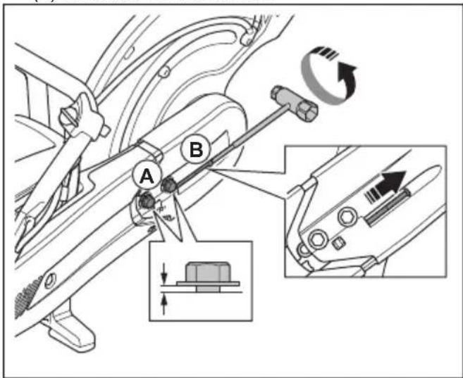
text_image
Technical diagram showing mechanical assembly with labeled parts A and B, including directional arrows and component details- Remove the 2 bolts.
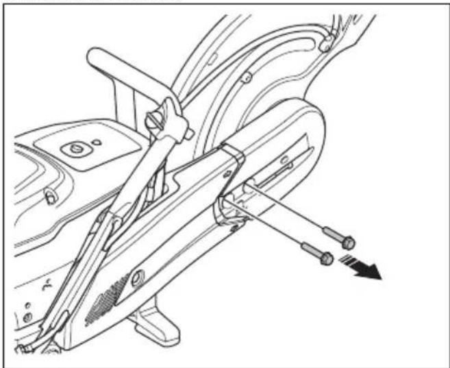
natural_image
Technical line drawing of a car's steering wheel assembly (no text or symbols)- Remove the front belt guard.
natural_image
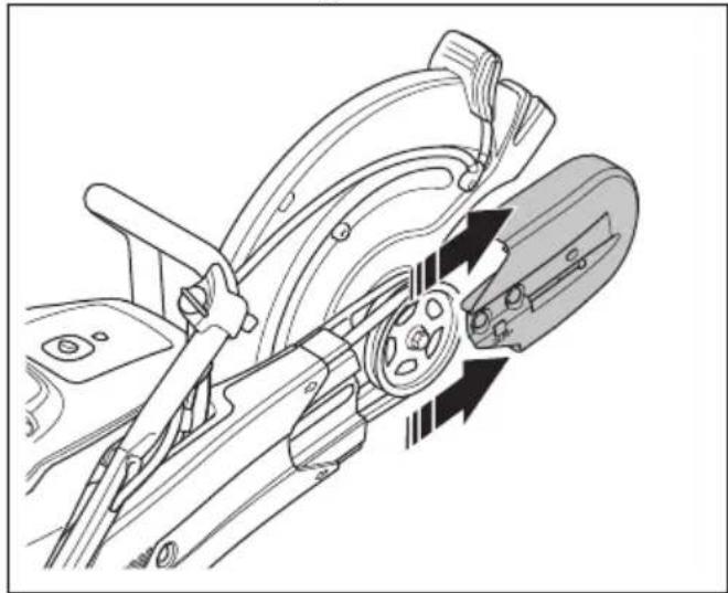
Technical line drawing of a mechanical assembly with directional arrows indicating motion or force (no text or symbols)- Remove the drive belt from the belt pulley and remove the cutting head.
text_image
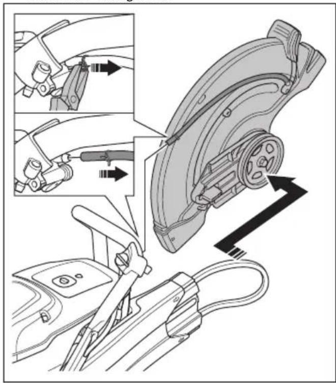
Technical diagram showing car brake assembly steps with labeled parts and directional arrows indicating motion- Remove the nut on the rear belt guard and remove the rear belt guard.
natural_image
Technical line drawing of a mechanical assembly with no visible text or symbols- Replace the drive belt.
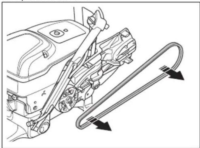
natural_image
Technical diagram of a car's internal engine compartment showing lever and guide rails (no text or labels)- Assemble in opposite sequence. To install the cutting blade, refer to To install the cutting blade on page 14.
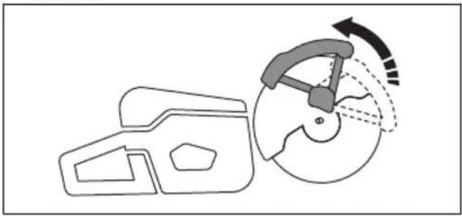
To adjust the tension of the drive belt
The tension of the drive belt is correct when the adjustment nut is opposite the mark on the drive belt cover.
natural_image
Technical diagram of a mechanical gear assembly with an inset showing a close-up of a component (no text or symbols present)- Loosen the 2 bolts that hold the cutting head to the product.
natural_image
Technical line drawing of a mechanical tool with a saw cutting through it, showing no text or symbols.- Turn the adjuster screws (A) until the adjustment nut (B) is opposite the mark on the drive belt cover.
text_image
Technical diagram of a mechanical device with labeled parts A and B, showing directional arrows and component layout.- Use a combination wrench and tighten the 2 bolts that hold the cutting head to the product.
Starter housing

WARNING: Always be careful and always use eye protection when you replace the recoil spring or the starter rope. There is tension in the recoil spring when it is wound in the starter housing. The recoil spring can eject and cause injury.
To remove the starter housing
- Loosen the 4 screws on the starter housing.
natural_image
Technical line drawing of a mechanical assembly with a motor and gear mechanism (no text or symbols)- Remove the starter housing.
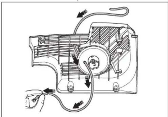
To replace a damaged starter rope
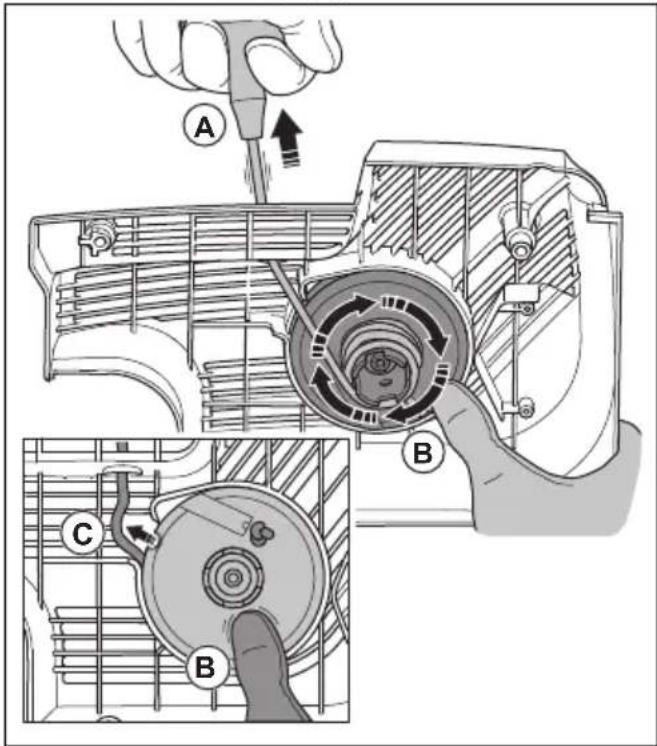
- Pull out the starter rope approximately 30 cm (A).
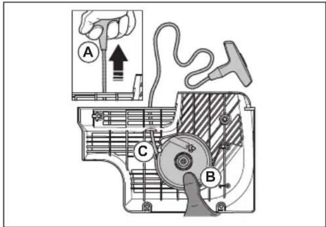
text_image
Technical diagram of a mechanical device with labeled parts A, B, and C, showing internal components and directional arrows.-
Hold the starter rope pulley (B) with your thumb.
-
Put the starter rope in the notch (C) in the starter pulley.
-
Put the starter rope around the metal sleeve.
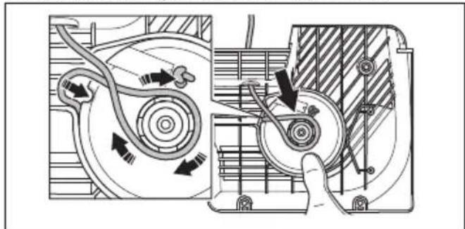
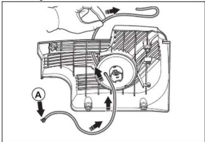
natural_image
Technical diagram of a mechanical assembly with directional arrows indicating motion or flow (no text or symbols present)- Let the starter pulley rotate slowly and the starter rope wind up on the metal sleeve.
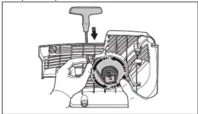
natural_image
Technical illustration of a mechanical assembly with hands holding a circular component (no text or symbols visible)- Pull the starter rope to release it from the metal sleeve.
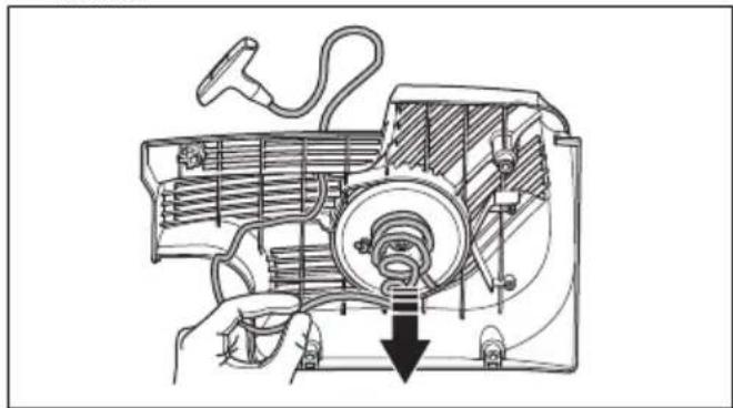
natural_image
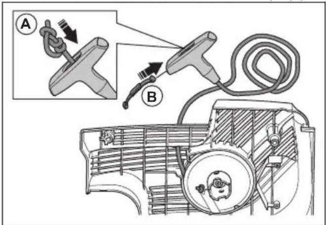
Technical line drawing of a mechanical device with a hand operating it, showing internal components and a downward arrow indicating motion (no text or symbols present)- Remove the cover on the starter rope handle (A).

text_image
Diagram illustrating cable installation steps with labeled components A, B, and C, showing cable routing from a vehicle chassis.- Pull the starter rope up through the handle (B).
- Release the knot (C).
- Remove the starter rope.
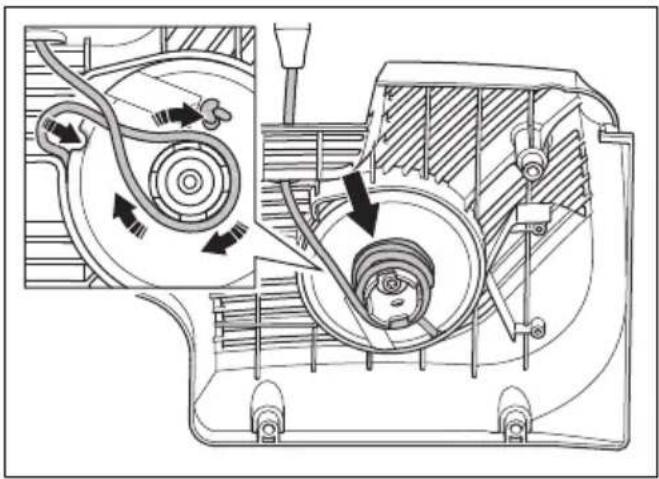
natural_image
Technical diagram of a mechanical device with internal components and directional arrows indicating flow or movement (no text or labels)- Make sure that the recoil spring is clean and not damaged.
- Put a new starter rope (A) in the hole in the starter housing.
text_image
Technical diagram of an air duct system with labeled components and directional arrows indicating flow or movement.- Pull the starter rope through the starter rope handle and make a knot at the end of the starter rope (A).
text_image
Diagram illustrating a car tire knot and rope routing process, labeled with parts A and B.- Attach the cover on the starter rope handle (B).
- Adjust the tension of the recoil spring. Refer to To adjust the tension of the recoil spring on page 33.
To adjust the tension of the recoil spring
- Pull out the starter rope.
- Put the starter rope in the notch and wind it up around the metal sleeve.
natural_image
Technical diagram of a mechanical device showing internal components and airflow paths (no text or labels)- Pull out the starter rope (A).
text_image
Technical diagram of a mechanical device with labeled parts A, B, and C showing internal components and assembly steps.- Put your thumb on the starter pulley (B) to keep the starter rope pulled out.
- Release the starter rope from the notch (C).
- Remove your thumb to release the starter pulley (A) and let the starter rope (B) wind up on the pulley.
text_image
Technical diagram of a mechanical device with labeled parts A and B, showing internal components and directional arrows.- Pull out the starter rope fully to do a check that the recoil spring is not at its end position. Make sure that the starter pulley can be turned half a turn or more before the recoil spring stops the movements.
To remove the spring assembly

WARNING: Always use eye protection when you disassemble the spring assembly.
There is a risk for eye injury, especially if a spring is broken.
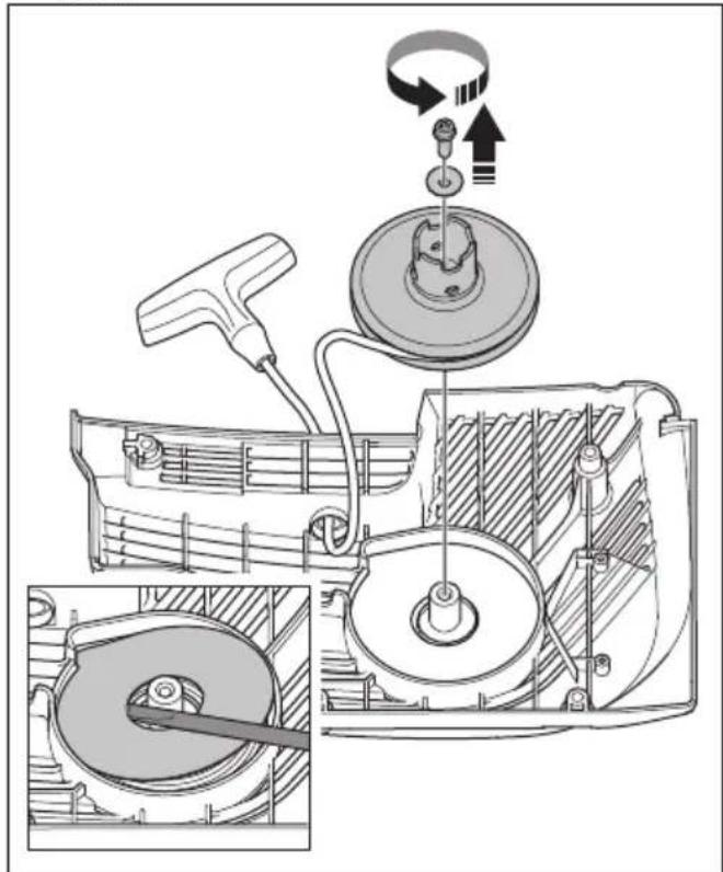
- Remove the bolt in the center of the starter pulley and remove the starter pulley. Carefully remove the cover.
natural_image
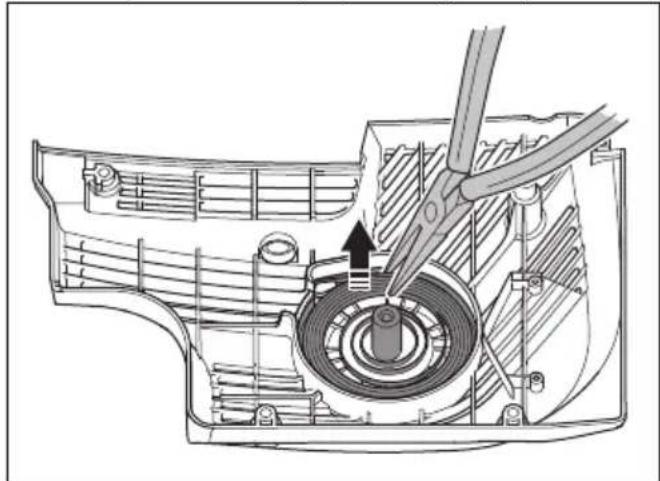
Technical illustration of a mechanical assembly with exploded view and close-up views (no text or symbols)The recoil spring has tension in the starter housing.
- Carefully remove the spring. Use a pair of pliers.
natural_image
Technical line drawing of a mechanical assembly with a tool inserted, showing internal components and a black arrow indicating a specific part (no text or symbols present)To clean the spring assembly

CAUTION: Do not remove the spring from the assembly.
- Blow the spring with compressed air until it is clean.
- Apply a light oil to the spring.
To attach the spring assembly
- Assemble in the opposite sequence of the spring assembly on page 33. To remove
To install the starter housing

CAUTION: The starter pawls must come into the correct position against the starter pulley sleeve.
- Put the starter against the product.
natural_image
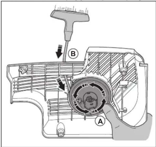
Technical line drawing of a mechanical assembly with gears and housing (no text or symbols)- Install the starter pawls into the correct position against the starter pulley sleeve. Pull out the starter rope approximately 0.5 m. (A). If the position is correct, you hear a click sound (B).

text_image
Medical diagram showing ear anatomy with labeled parts A and B, including a magnified inset of the ear.-
Slowly release the starter rope.
-
Tighten the 4 screws on the starter
natural_image
Technical line drawing of a mechanical device with gear and adjustment knobs (no text or symbols)To examine the carburetor
Note: The carburetor has rigid needles to make sure that the product always receives the correct mixture of fuel and air.
- Examine the air filter. Refer to To examine the air filter on page 35
- If it is necessary, replace the air filter.
- If the engine continues to decrease in power or speed, speak to your HUSQVARNA servicing dealer.
To examine the fuel system
- Make sure that the fuel tank cap and its seal are not damaged.
- Examine the fuel hose. Replace the fuel hose if it is damaged.
To adjust the idle speed
WARNING: If the cutting blade rotates at idle speed, speak to your servicing dealer. Do not use the product until the idle speed is correctly adjusted or repaired.
Note: For recommended idle speed refer to Technical data on page 39.
- Start the engine.
-
Examine the idle speed. When the carburetor is correctly adjusted, the cutting blade stops when the engine is at idle speed.
-
Use the T screw to adjust the idle speed.
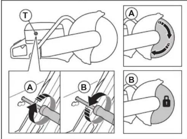
text_image
Technical diagram illustrating mechanical assembly steps with labeled components A and B, including tool positioning and lock mechanisma) Turn the screw clockwise until the blade starts to rotate (A).
b) Turn the screw counterclockwise until the blade stops to rotate (B).
Fuel filter
The fuel filter is installed in the fuel tank. The fuel filter prevents contamination of the fuel tank when the fuel tank is filled. The fuel filter must be replaced yearly or more frequently if it is clogged.

CAUTION: Do not clean the fuel filter.
To examine the air filter
Note: Examine the air filter only if the engine power decreases.
CAUTION: Be careful when you remove the air filter. Particles that fall into the carburetor inlet can cause damage.

WARNING: Use approved respiratory protection when you clean or replace the air filter. Discard used air filters correctly. The dust in the air filter is dangerous to your health.
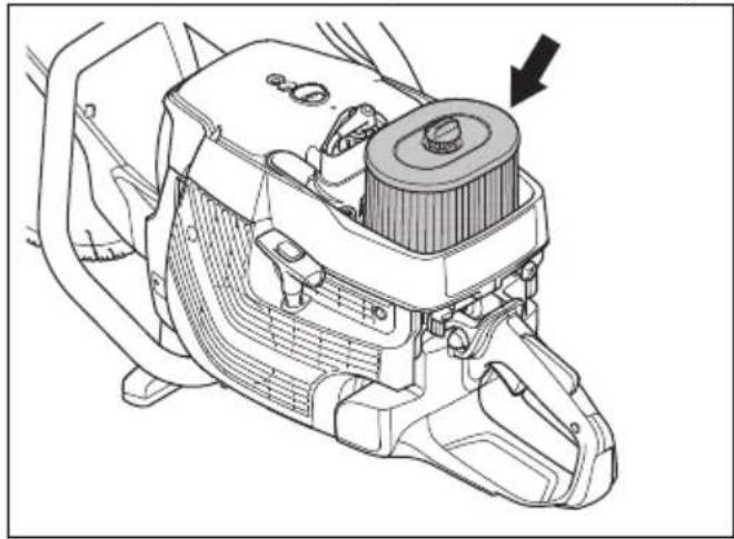
- Loosen the 3 screws on the air filter cover.
-
Remove the air filter cover.
-
Examine the air filter and replace it if it is necessary.
natural_image
Technical line drawing of a mechanical assembly with no visible text or symbols
CAUTION: Do not clean the air filter or blow compressed air on it. This will do damage to the air filter.
- Replace the air filter if it is necessary.
a) Loosen the screw on the air filter housing and remove it.
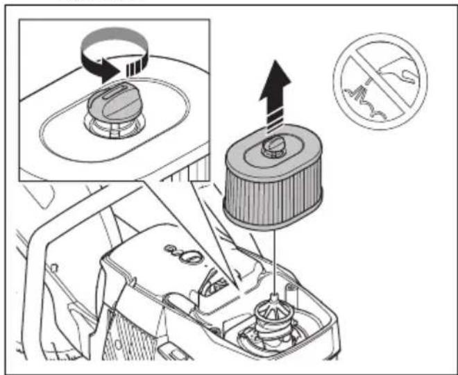
text_image
Diagram illustrating car exhaust system with labeled components and a no-smoking symbolb) Install the new air filter.
- Attach the air filter cover and tighten the 3 screws.
To do a check of the water supply system
- Examine the nozzles on the blade guard and make sure that they are not clogged.
- Clean as necessary.
- Examine the filter on the water connector. Make sure that it is not clogged.
- Clean as necessary.
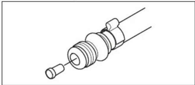
natural_image
Technical line drawing of a mechanical component with threaded end and shaft (no text or symbols)- Examine the hoses and make sure that they are not damaged.
Troubleshooting
| Problem Cause Possible solutions | ||
| The product does not start. | The start procedure is done incorrectly. | Refer to To start the product with a cold engine on page 22 and To start the product with a warm engine on page 24. |
| The stop switch in the right (STOP) position. | Make sure that the stop switch (STOP) is in the left position. | |
| There is no fuel in the fuel tank. Fill with fuel. | ||
| The spark plug is defective. Replace the spark plug. | ||
| The clutch is defective. Speak to your service agent. | ||
| The cutting blade rotates at idle speed. | The idle speed is too high. Adjust the idle speed. | |
| The clutch is defective. Speak to your service agent. | ||
| The cutting blade does not rotate when the operator throttles up. | The belt is too loose or defective. | Tighten the belt or replace the belt with a new one. |
| The clutch is defective. Speak to your service agent. | ||
| The cutting blade is installed incorrectly. | Make sure that the cutting blade is correctly installed. | |
| The product has no power when the operator tries to throttle up. | The air filter is clogged. | Examine the air filter. If it is necessary, replace it. |
| The fuel filter is clogged. Replace the fuel filter. | ||
| The fuel tank flow is blocked. Speak to your service agent. | ||
| The vibration levels are too high. | The cutting blade is installed incorrectly. | Make sure that the cutting blade is correctly installed and that it is not damaged. Refer to To install the cutting blade on page 14. |
| The cutting blade is defective. | Replace the cutting blade and make sure that it is not damaged. | |
| A vibration damping unit is defective. Speak to your service agent. | ||
| The temperature of the product is too high. | The air intake or the cylinder flanges are blocked. | Clean the air intake and the cylinder flanges. |
| The drive belt tension is not sufficient. | Examine the belt. Adjust the tension. | |
| The clutch is defective. | Always cut at full throttle. | |
| Examine the clutch. Speak to your service agent. | ||
| The engine decreases in power or in speed. | The air filter is clogged. Examine the air filter. Refer to To examine the air filter on page 35. | |
| There is much dust during operation. You can see dust in the air. | The water supply or water pressure is not sufficient. | Do a check of the water supply to the product. |
| Refer to To do a check of the water supply system on page 36. | ||
| The SmartGuard does not move freely. | The moving parts of the SmartGuard are clogged. | Clean the moving parts. |
| The SmartGuard does not retract when the product is removed away from the work piece. | The springs of the SmartGuard does not operate correctly. | Do a check of the springs. Clean the springs. |
Transportation, storage and disposal
Transportation and storage

CAUTION: Do not install the rail fixture to the product during transport of the product. The rail fixture is a precision tool. A damaged tool gives less accurate cuts.

text_image
Safety warning illustration showing two workers in protective gear holding fire extinguishers, with one crossed out by a 'X' symbol.- Keep the rail fixture separated from the product in the supplied box.
- Secure the product during transportation to prevent damage and accidents.
- Remove the cutting blade before transportation or storage of the product.
- Keep the product in a locked area to prevent access for children or persons that are not approved.
- Keep the cutting blades in dry, frost free conditions.
- Examine all new and used blades for transport and storage damage before assembly.
- Clean and maintain the product before storage. Refer to Maintenance on page 27.
- Remove the fuel from the fuel tank before long-term storage.
Disposal
- Obey the local recycling requirements and applicable regulations.
- Discard all chemicals, such as oil or fuel, at a service center or at an applicable disposal location.
- When the product is no longer in use, send it to a HUSQVARNA dealer or discard it at a recycling location.
Technical data
Technical data
| K 1270 II K 1270 II Rail | K 1270 Smart-Guard | ||
| Cylinder displacement, cm3/cu.in. 119/7.3 119/7.3 119/7.3 | |||
| Cylinder bore, mm/in. 60/2.4 60/2.4 60/2.4 | |||
| Travel length, mm/in. 42/1.7 42/1.7 42/1.7 | |||
| Idle speed, rpm 2700 2700 2700 | |||
| Wide open throttle, no load, rpm 9300 (+/- 150) 9300 (+/- 150) 9300 (+/- 150) | |||
| Power, kW/hp @rpm 5.8 /7.9 @8400 5.8 /7.9 @8400 5.8 /7.9 @8400 | |||
| Spark plug NGK BPMR 7A NGK BPMR 7A NGK BPMR 7A | |||
| Electrode gap, mm/in. 0.5/0.02 0.5/0.02 0.5/0.02 | |||
| Fuel tank capacity, liters/US fl oz | 1.2/40 1.2/40 | 1.2/40 | |
| Recommended water pressure, bar/PSI | 0.5-10/7-150 | N/A | 0.5-10/7-150 |
| Weight | |||
| Power cutter without fuel and cutting blade 350mm (14in.), kg/lb | 13.6/30.0 | 15.3/33.7 | N/A |
| Power cutter without fuel and cutting blade 400mm (16in.) kg/lb | 14.2/31.3 | 16.0/35.3 | 15.1/33.3 |
| Rail fixture kg/lb | |||
| RA 10 | N/A | 5.5/12.1 | N/A |
| RA 10 S | N/A | 5.7/12.6 | N/A |
| Spindle, output shaft | |||
| Max. spindle speed with cutting blade 350mm (14in.), rpm | 4700 4700 4700 | ||
| Max. spindle speed with cutting blade 400mm (16in.), rpm | 4300 4300 4300 | ||
| Max. peripheral speed, m/s or ft/min | 90 or 18000 | 90 or 18000 | 90 or 18000 |
| Noise emissions 1 | |||
| Sound power level, measured dB (A) | 116 | 116 | 116 |
| Sound power level, guaranteed LWA dB (A) | 117 | 117 | 117 |
| Sound levels 2 | |||
| Equivalent sound pressure level at the ear of the operator, dB (A) | 104 104 104 | ||
| Equivalent vibration levels, a_hveq^3 | |||
| Front/ rear handle 14in. 4.5/3.7 3.4/3.5 N/A | |||
| Front/ rear handle 16in. 3.9/4.0 4.4/3.9 4.7/4.8 | |||
Recommended cutting blade dimensions
| Cutting blade diameter, in./mm | Max. cutting depth, mm/in. | Blade speed rat-ing, rpm | Blade speed rat-ing, m/s or ft/min | Blade center hole diameter, mm/in. | Max. blade thickness, mm/in. |
| 14/350 118/4.6 550 | 100 or 19600 25 | 4/1 or 20/0.79 5/0.2 | |||
| 16/400 145/5.7 480 | 100 or 19600 25 | 4/1 or 20/0.79 5/0.2 |
Noise and vibration declaration statement
These declared values were obtained by laboratory type testing in accordance with the stated directive or standards and are suitable for comparison with the declared values of other products tested in accordance with the same directive or standards. These declared
values are not suitable for use in risk assessments and values measured in individual work places may be higher. The actual exposure values and risk of harm experienced by an individual user are unique and depend upon the way the user works, in what material the product is used, as well as upon the exposure time and the physical condition of the user, and the condition of the product.
Accessories
Sensor for Husqvarna Fleet Services™
This product is compatible with the Husqvarna Fleet machine sensor. The product can then be connected to Husqvarna Fleet Services ^™ , which is a cloud solution that gives the commercial fleet manager an overview of all products. For more information about Husqvarna Fleet Services ^™ , refer to www.husqvarna.com.
Wheel kit
The wheel kit is attached at the bottom of the product.
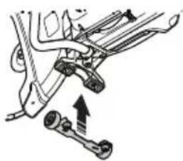
natural_image
Mechanical assembly diagram showing linkage components with an upward arrow (no text or labels)Cutting trolley
A cutting trolley makes it easier to cut in floors and roads, especially long cuts at a set depth. Quick connections make it easy to install the product on the cutting trolley.
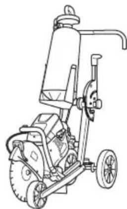
natural_image
Line drawing of a mechanical power tool with wheels and a central pump (no text or symbols)Declaration of Conformity
EU Declaration of Conformity
We, Husqvarna AB, SE-561 82 Huskvarna, Sweden, tel: +46-36-146500, declare on our sole responsibility that the product:
| Description Portable cut-off machine | |
| Brand HUSQVARNA | |
| Type/Model K 1270 II, K 1270 II Rail, K 1270 SmartGuard | |
| Identification Serial numbers dating from 2021 and onwards |
complies fully with the following EU directives and regulations:
| Directive/Regulation Description | |
| 2006/42/EC "relating to machinery" | |
| 2000/14/EC "relating to outdoor noise" | |
| 2014/30/EU "relating to electromagnetic compatibility" | |
| 2011/65/EU "relating to restriction of hazardous substances" |
and that the following harmonized standards and/or technical specifications are applied;
EN ISO 12100:2010, EN ISO 19432-1:2020, EN 55012:2008+A1:2009, EN ISO 14982:2009, EN IEC 63000:2018.
2000/14/EC, conformity assessment procedure: Annex V. For information relating to noise emissions, refer to Technical data on page 39.
Partille, 2021-04-29

Erik Silfverberg
R&D Director, Concrete Sawing & Drilling Equipment
Husqvarna AB, Construction Division
Responsible for technical documentation

UK Declaration of Conformity
We, Husqvarna AB, SE-561 82 Huskvarna, Sweden, tel:
+46-36-146500, declare on our sole responsibility that
the product:
| Description Portable cut-off machine | |
| Brand HUSQVARNA | |
| Type/Model K 1270 II, K 1270 II Rail, K 1270 SmartGuard | |
| Identification Serial numbers dating from 2021 and onwards |
complies fully with the following UK directives and
regulations:
| Regulation Description | |
| S.I. 2008/1597 The Supply of Machinery (Safety) Regulations 2008 | |
| S.I. 2016/1091 Electromagnetic Compatibility Regulations 2016 | |
| S.I. 2001/1701 The Noise Emission in the Environment by Equipment for use Outdoors Regulations 2001 | |
| S.I. 2012/3032 The Restriction of the Use of Certain Hazardous Substances in Electrical and Electronic Equipment Regulations 2012 | |
and that the following harmonized standards and/or technical specifications are applied;
EN ISO 12100:2010, EN ISO 19432-1:2020, EN
55012:2008+A1:2009, EN ISO 14982:2009, EN IEC
63000:2018.
Conformity assessment procedure acc S.I. 2001/1701:
Schedule 8. For information relating to noise emissions, refer to Technical data on page 39.
Partille, 2021-04-29

UK Importer:
Husqvarna UK Limited
Preston Road, Aycliffe
Business Park Newton
Aycliffe, County Durham
UK DL5 6UP
Erik Silfverberg
R&D Director, Concrete Sawing & Drilling Equipment
Husqvarna AB, Construction Division
Responsible for technical documentation
UK
CA
Inhalt
text_image
Technical diagram of a mechanical device with numbered parts for identification and assembly reference.text_image
Technical diagram of a mechanical device with numbered parts for identification and assembly reference.text_image
Technical diagram of a mechanical device with numbered parts, including a book icon and a control panel inset.natural_image
Illustration of a person in full safety gear with first aid kit (no text or symbols)text_image
Technical diagram of a mechanical assembly with labeled parts A and Bnatural_image
Technical line drawing of a mechanical component with an arrow indicating a specific part (no text or symbols present)natural_image
Technical line drawing of a mechanical component with an arrow indicating a specific part (no text or symbols present)natural_image
Technical line drawing of a mechanical component with directional arrows indicating assembly or movement (no text or symbols present)natural_image
Technical line drawing of a mechanical component with an inset showing a close-up of a component (no text or symbols present)text_image
Diagram of a car interior with labeled parts A, B, and C indicating different components or areas.natural_image
Diagram of a car's seat and steering wheel assembly (no text or labels)natural_image
Three types of threaded mechanical components shown in line drawings (no text or symbols)natural_image
Technical line drawing of two interlocking gears with no text or symbolsnatural_image
Diagram of a geological cross-section showing layered strata with no text or symbolsnatural_image
Circular mechanical gear diagram with evenly spaced teeth and central bore (no text or symbols)natural_image
Diagram of a mechanical component with two circular parts and directional arrows indicating motion (no text or symbols)natural_image
Simple line drawing of a gear and cam mechanism with a black arrow pointing to the gear (no text or symbols)text_image
Technical diagram showing mechanical assembly with gear and component details, including a circular component and rotational motion arrow.natural_image
Diagram of a car steering wheel and its motion, showing gear shift and wheel (no text or symbols)text_image
Diagram of a mechanical device with labeled parts A, B, and C showing internal components and alignment.natural_image
Line drawing of a mechanical device with no visible text or symbolsnatural_image
Technical line drawing of a mechanical assembly with a tool and component (no text or symbols)natural_image
Technical diagram of a car brake caliper assembly with directional arrows and inset showing internal components (no text or labels)natural_image
Technical line drawing of a bicycle steering wheel assembly with mounting brackets and gear mechanism (no text or symbols)natural_image
Technical line drawing of a mechanical device with attached clamps and tubing (no text or symbols)natural_image
Technical line drawing of a mechanical component with no visible text or symbolsnatural_image
Technical diagram of a mechanical component with a curved housing and internal gear mechanism (no text or labels)natural_image
Mechanical assembly diagram showing a wheel and bracket assembly with directional arrows (no text or labels)natural_image
Diagram showing a mechanical component interacting with a circular object, with directional arrows indicating motion (no text or symbols)text_image
Technical diagram showing a mechanical component with a warning symbol and directional arrows indicating motion or flow.text_image
Safety instruction diagram showing a worker using a tool to clean air, with an inset illustrating hazard zones.text_image
Safety warning illustration showing a worker crossed over a gear with a cross symbol, alongside an accident hazard symbol.Blockierung
natural_image
Diagram of a medical or surgical procedure with a cross symbol over a tool, no text or labels presenttext_image
Diagram illustrating a mechanical tool application with a hand operating a tool and a cross symbol indicating no change or failure.natural_image
Simple line drawing of a plastic bag and a magnifying glass with a downward arrow (no text or symbols)natural_image
Diagram showing a mechanical component with a circular target and directional arrows, no text or symbols present.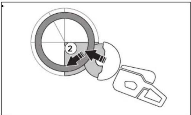
text_image
Diagram showing a circular component with labeled parts and directional arrows, likely illustrating a mechanical or electrical process.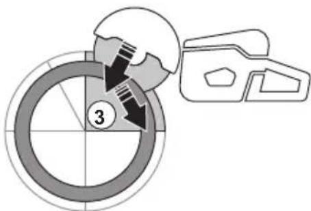
text_image
3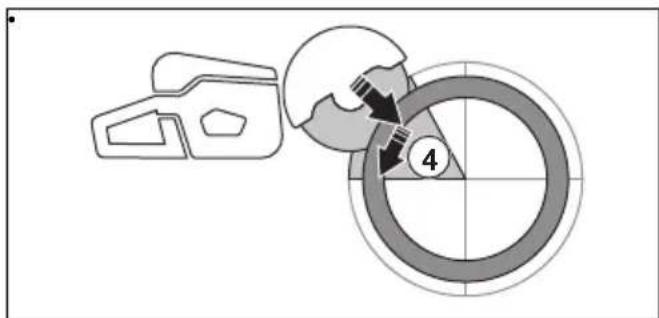
text_image
4natural_image
Two diagrams showing a cross-shaped object with downward arrows and triangular supports, next to a U-shaped object with downward arrow (no text or symbols)natural_image
Line drawing of a person using a handheld device to interact with another person (no text or symbols present)text_image
Diagram illustrating a hand holding a device before and after disassembly, with a cross symbol indicating disassembly.natural_image
Diagram of a mechanical device with a rotating shaft and base, showing motion direction (no text or symbols)text_image
Safety warning illustration showing two workers in protective gear using a ladder and cross symbol to prevent equipment damage.natural_image
Line drawing of a person using a handheld device to lift or lift an object, wearing boots (no text or symbols)natural_image
Diagram showing two mechanical components with a cross mark, no text or symbols presentnatural_image
Line drawing of a person using a cutting tool to cut a saw (no text or symbols present)text_image
Safety warning illustration showing fuel injection and hazard symbols for a worker in protective geartext_image
Row of eight black-and-white icons representing various heating and cooling systems, including thermometer, valve, 6X, and directional arrows.
natural_image
Line drawing of a car gear shift lever with a black arrow indicating the direction (no text or symbols present)natural_image
Technical line drawing of a mechanical component with an inset showing a pin assembly (no text or symbols present)natural_image
Technical line drawing of a mechanical component with no visible text or symbolsnatural_image
Illustration of a worker in safety gear performing manual labor on a stretcher (no text or symbols)
natural_image
Technical line drawing of a mechanical component with an inset showing a pin inserted into a housing (no text or symbols present)natural_image
Technical line drawing of a mechanical component with directional arrows indicating movement or force (no text or symbols present)text_image
Diagram showing five different weather and heating symbols with corresponding icons and labels
natural_image
Line drawing of a car gear shift lever with a downward arrow indicating the direction (no text or symbols present)natural_image
Technical line drawing of a mechanical component with an inset showing a pin assembly (no text or symbols present)natural_image
Technical line drawing of a mechanical component with an inset showing a pin inserted into a housing (no text or symbols present)natural_image
Illustration of a worker in safety gear cutting a large cylindrical object (no text or symbols)
natural_image
Technical diagram of a mechanical assembly with directional arrows indicating movement or force (no text or symbols present)text_image
Technical diagram showing a mechanical component with an inset highlighting a specific part labeled '50mm'.text_image
Safety warning illustration showing cross symbol crossed out of a person in protective gear, with another figure holding fire extinguisher equipment.natural_image
Mechanical clamp mechanism diagram showing lever and guide assembly (no text or symbols)natural_image
Technical line drawing of a mechanical clamp and wheel assembly (no text or symbols)natural_image
Technical line drawing of a mechanical device with a circular component and directional arrows (no text or symbols)natural_image
Diagram showing a mechanical device with directional arrows indicating motion or force (no text or symbols present)text_image
Diagram illustrating rail track joint movements with labeled points A, B, and C, showing structural changes and motion directions.natural_image
Technical illustration of a mechanical clamp or clamping device with hands operating it (no text or symbols visible)natural_image
Technical illustration of a hand operating a mechanical device with an inset showing a left-hand rule and a close-up of the lever mechanism (no text or symbols present)natural_image
Three abstract line drawings showing different mechanical or structural configurations (no text or symbols)natural_image
Technical diagram of a car air vent or airflow system showing airflow path and component placement (no text or labels)natural_image
Diagram of a car interior showing dashboard, intake manifold, and fan (no text or symbols)text_image
Diagram illustrating car engine toolpath and valve mechanism with checkmark and cross symbols indicating correct and incorrect statestext_image
Technical diagram illustrating engine tool manipulation steps with labeled diagrams and arrows indicating action sequencenatural_image
Line drawing of a mechanical device with a tool and circular component (no text or symbols)text_image
Technical diagram of a mechanical assembly with labeled parts A and B, showing directional arrows and component details.natural_image
Technical line drawing of a car suspension system with mechanical components and motion arrows (no text or symbols)natural_image
Technical line drawing of a mechanical assembly with no visible text or symbolstext_image
Technical diagram showing car seat assembly with labeled parts and directional arrows indicating fastening or locking mechanism.natural_image
Technical line drawing of a mechanical assembly with no visible text or symbolsnatural_image
Technical line drawing of a car engine compartment with attached suspension components (no text or symbols)natural_image
Technical diagram of a mechanical device with gear and adjustment arrows, no readable text or symbols presentnatural_image
Technical line drawing of a mechanical tool or saw cutting process, showing blade and gear assembly (no text or symbols)text_image
Technical diagram illustrating mechanical assembly with labeled parts A and B, showing directional arrows and a checkmark indicating inspection or adjustment.natural_image
Technical line drawing of a mechanical assembly with a motor and gear mechanism (no text or symbols)text_image
Technical diagram of a mechanical device with labeled components A, B, and C, showing internal structure and directional arrows.natural_image
Technical diagram of a mechanical assembly with rotating components and directional arrows (no text or labels)natural_image
Technical illustration of a mechanical assembly with hands holding a circular component (no text or symbols visible)natural_image
Technical line drawing of a mechanical device with internal components and a downward arrow indicating a component (no text or symbols present)text_image
Diagram illustrating cable installation steps with labeled components A, B, and C, showing cable connection to a vehicle chassis.natural_image
Technical diagram of a mechanical device with internal components and wiring, no visible text or symbolstext_image
Technical diagram of a mechanical device with labeled components and directional arrows indicating flow or movement.text_image
Diagram illustrating a car tire knot and rope installation with labeled parts A and B, showing mechanical components and assembly.natural_image
Technical line drawing of a mechanical device with internal components and directional arrows indicating flow or movement (no text or symbols)text_image
Technical diagram of a mechanical device with labeled parts A, B, and C showing internal components and directional arrows.text_image
Technical diagram of a mechanical device with labeled parts A and B, showing internal components and directional arrows.natural_image
Technical illustration of a mechanical assembly with exploded view and close-up views (no text or symbols)natural_image
Technical line drawing of a mechanical assembly with a tool inserted, showing internal components and a central component (no text or symbols)natural_image
Technical line drawing of a mechanical assembly with no visible text or symbolstext_image
Technical diagram of a medical or automotive device with labeled parts A and B, showing mechanical components and a magnified inset of the ear.natural_image
Technical line drawing of a mechanical device with gear and adjustment arrows (no text or symbols)Vergaser überprüfen
text_image
Diagram illustrating mechanical assembly steps with labeled components A, B, and T, showing tool path and lock mechanism.natural_image
Technical line drawing of a mechanical assembly with a central component and an arrow indicating direction (no text or symbols present)
text_image
Diagram illustrating a mechanical device with an inset showing a component being lifted, accompanied by a no-smoking symbol.natural_image
Line drawing of a mechanical component with threaded body and connector (no text or symbols)text_image
Safety warning sign showing a person with crossed-out X symbol and fire extinguisher icon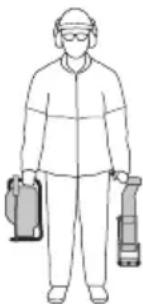
natural_image
Line drawing of a person wearing protective gear and holding two equipment cases (no text or symbols)natural_image
Mechanical assembly diagram showing two connected components with directional arrows indicating motion (no text or labels)Führungswagen
natural_image
Line drawing of a mechanical power tool with wheels and a cylindrical component (no text or symbols)Husqvarna AB, Construction Division
text_image
Technical diagram of a saw cutting machine with numbered parts for identification and assembly reference.text_image
Technical diagram of a mechanical device with numbered parts, including a close-up inset of the book.text_image
Technical diagram of a mechanical device with numbered parts, including a book icon and a control panel inset.Précautions relatives aux vibrations

natural_image
Illustration of a person wearing full protective gear standing next to a first aid kit (no text or symbols)text_image
Technical diagram of a mechanical component with labeled parts A and Bnatural_image
Technical line drawing of a mechanical component with an arrow indicating a specific feature (no text or symbols present)natural_image
Technical line drawing of a mechanical component with no visible text or symbolsnatural_image
Technical line drawing of a mechanical component with directional arrows indicating movement or assembly (no text or symbols present)text_image
Technical diagram showing a mechanical component with an inset highlighting a stop button mechanism.text_image
Diagram of a mechanical device with labeled parts A, B, and C, showing internal components and assembly.natural_image
Diagram of a car interior showing steering wheel and gear mechanism (no text or symbols)natural_image
Three identical mechanical screw components shown in isometric view, no text or symbols presentnatural_image
Technical line drawing of two interlocking gears with no text or symbolsnatural_image
Diagram of a geological cross-section showing layered strata with no text or symbolsnatural_image
Circular mechanical component with evenly spaced teeth and central bore, no text or symbols presentnatural_image
Diagram of a mechanical component with two circular parts and directional arrows indicating motion (no text or symbols)natural_image
Simple line drawing of a gear and cam mechanism with a black arrow pointing to the gear (no text or symbols)text_image
Diagram illustrating gear meshing process with labeled components and rotation directionnatural_image
Diagram of a mechanical device with rotating components and directional arrows (no text or symbols)text_image
Diagram of a mechanical device with labeled parts A, B, and C showing internal components and motion paths.natural_image
Line drawing of a mechanical device with a lever and base mount (no text or symbols)natural_image
Technical line drawing of a mechanical tool interacting with a cutting board (no text or symbols)natural_image
Mechanical assembly diagram showing a pulley mechanism and its internal components (no text or labels)natural_image
Technical line drawing of a mechanical component with internal parts and directional arrows indicating assembly (no text or symbols)natural_image
Technical line drawing of a mechanical device with attached clamps and a central component (no text or symbols)natural_image
Technical line drawing of a mechanical component with no visible text or symbolsnatural_image
Mechanical component diagram showing a rotating wheel and housing mechanism (no text or symbols)natural_image
Mechanical assembly diagram showing a wheel and bracket assembly with directional arrows (no text or labels)natural_image
Diagram showing a mechanical component and a circular object with directional arrows, no text or symbols present.text_image
Diagram illustrating safety hazard with a warning sign and gear mechanism, showing mechanical components and safety symbols.Rebond rotationnel
text_image
Safety instruction illustration showing a worker using a power tool to adjust equipment with a warning symbol and safety hazard.Rebond de grimpée
text_image
Safety warning illustration showing a worker crossed over a gear with a cross symbol, alongside a technical diagram of a gear fault.Rebond de pincement
natural_image
Diagram of a medical procedure with a surgical tool and X-shaped cross symbol (no text or labels)text_image
Diagram illustrating a mechanical or robotic operation with labeled components and directional arrows indicating movement.natural_image
Simple line drawing of a car outline and a circular diagram with a downward arrow (no text or symbols)text_image
Diagram showing a magnifying glass interacting with a circular target, labeled with number 1 and directional arrows.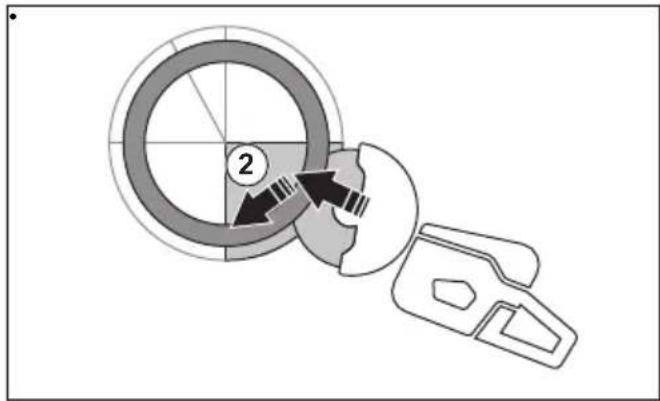
text_image
Diagram showing a circular component with labeled parts and directional arrows, likely illustrating a mechanical or electrical process.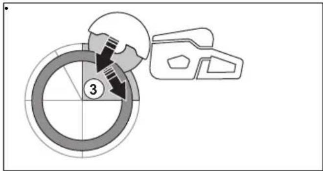
text_image
③
text_image
Diagram showing a mechanical assembly with labeled component '4' and directional arrows indicating motion or movement.natural_image
Two schematic diagrams showing a beam with cross-shaped load and a stepped beam with triangular supports, no text or symbols present.natural_image
Line drawing of a person using a handheld device to interact with another person (no text or symbols present)text_image
Diagram illustrating hand positioning and crossed-out gesture with directional arrows, showing correct and incorrect states.natural_image
Diagram of a mechanical device with a rotating shaft and base, showing motion direction (no text or symbols)text_image
Safety warning illustration showing two workers with crossed-out X-shaped signs, one using a ladder to smoke and the other holding a helmet.natural_image
Line drawing of a person using a handheld tool on their lower legs (no text or symbols)natural_image
Diagram showing two mechanical components with a crossed-out black X mark, each with directional arrows indicating movement or force (no text or symbols)natural_image
Line drawing of a person using a power saw to cut a chain (no text or symbols present)text_image
Safety warning illustration showing fuel injection and discharge symbols with cross symbols, alongside a uniformed officer holding a bag.text_image
Row of seven black-and-white icons representing various mechanical or industrial components, including thermometer, valve, 6x, hammer, gear, and motion arrow.
natural_image
Line drawing of a car gear shift lever with a downward arrow indicating the direction (no text or symbols present)natural_image
Technical line drawing of a mechanical component with an inset showing a pin assembly (no text or symbols present)natural_image
Technical line drawing of a mechanical component with internal structure and a black arrow indicating a feature (no text or symbols present)natural_image
Illustration of a worker in safety gear performing a manual labor or cutting operation (no text or symbols visible)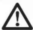
natural_image
Technical line drawing of a mechanical component with an inset showing a pin inserted into a housing (no text or symbols present)natural_image
Technical line drawing of a mechanical component with directional arrows indicating movement or force (no text or symbols present)text_image
Six labeled icons representing different heating and cooling system symbols, including thermometer, valve, down arrow, valve, down arrow, down arrow, and cross.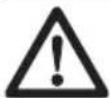
natural_image
Line drawing of a car gear shift lever with a downward arrow indicating the direction (no text or symbols present)natural_image
Technical line drawing of a mechanical assembly with an inset showing a pin inserted into a housing (no text or symbols present)natural_image
Technical line drawing of a mechanical component with an inset showing a pin inserted into a housing (no text or symbols present)natural_image
Illustration of a worker in safety gear performing manual labor on a wheel (no text or symbols)
natural_image
Technical line drawing of a mechanical component with directional arrows indicating movement or force (no text or symbols present)text_image
Technical diagram showing a mechanical component with an inset highlighting a stop button labeled 'STOP'text_image
Safety warning illustration showing two individuals in protective gear holding fire extinguishers, with one marked by a crossed X symbol.Installation de la fixation de rail
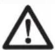
natural_image
Mechanical clamp mechanism diagram showing lever and guide assembly (no text or symbols)natural_image
Technical line drawing of a mechanical assembly with a clamp and wheel (no text or symbols)natural_image
Technical line drawing of a mechanical device with a circular component and directional arrows indicating motion (no text or symbols)natural_image
Diagram showing a mechanical device with directional arrows indicating motion or force (no text or symbols present)- Découpez le rail.
text_image
Diagram illustrating rail track joint movements with labeled points A, B, and C, showing structural changes and motion directions.natural_image
Technical line drawing of a mechanical clamp or clamping device with a wheel and handle (no text or symbols)text_image
Technical diagram showing a hand operating a mechanical device with directional arrows indicating movement or assembly.e) Continuez de rincer.
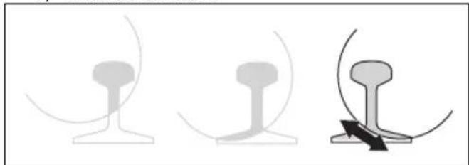
natural_image
Three abstract line drawings showing different mechanical or structural configurations (no text or symbols)natural_image
Technical diagram of a vehicle's air vent system showing airflow path and component placement (no text or labels)natural_image
Interior view of a car showing dashboard and steering wheel (no text or symbols)text_image
Diagram illustrating car intake and exhaust behavior with labeled parts and checkmark indicatorstext_image
Technical diagram illustrating engine component assembly and valve mechanism, with labeled parts and directional arrows indicating motion.natural_image
Line drawing of a mechanical device with a cylindrical component and lever (no text or symbols)text_image
Technical diagram showing mechanical assembly with labeled parts A and B, including directional arrows and component detailsnatural_image
Technical line drawing of a mechanical assembly with no visible text or symbolsnatural_image
Technical line drawing of a mechanical assembly with directional arrows indicating motion or force (no text or symbols)text_image
Technical diagram showing car seat assembly with labeled parts and directional arrows indicating movement or adjustment.natural_image
Technical line drawing of a mechanical assembly with no visible text or symbolsnatural_image
Technical line drawing of a car's internal components with directional arrows indicating motion or assembly (no text or symbols)text_image
Technical diagram showing mechanical components with a magnified inset highlighting a key mechanism with directional arrows.natural_image
Technical line drawing of a mechanical tool or bracket with a gear and base, showing no text or symbols.text_image
Technical diagram showing mechanical assembly with labeled parts A and B, including directional arrows and a checkmark indicating inspection or status.natural_image
Technical diagram of a mechanical assembly with labeled parts and directional arrows (no text or symbols)text_image
Technical diagram of a mechanical device with labeled parts A, B, and C, showing internal components and directional arrows.natural_image
Technical diagram of a mechanical device showing internal components and directional arrows (no text or labels)natural_image
Illustration of a hand assembling a mechanical component with a tool and internal gear (no text or symbols)natural_image
Technical line drawing of a mechanical device with a hand operating the housing and a black arrow indicating a downward motion (no text or symbols present)text_image
Diagram illustrating three stages of a mechanical or electrical device operation, labeled A, B, and C, with arrows indicating connection or movement.natural_image
Cross-sectional diagram of a mechanical device showing internal components and airflow paths (no text or labels)text_image
Technical diagram of an air duct system with labeled components and directional arrows indicating flow or movement.text_image
Technical diagram showing mechanical assembly with labeled parts A and B, including a rope knot and cable connection.natural_image
Technical line drawing of a mechanical device showing internal components and directional arrows (no text or symbols)text_image
Technical diagram illustrating a mechanical assembly with labeled parts A, B, and C, showing tool path and component layout.text_image
Technical diagram of a mechanical device with labeled parts A and B, showing internal components and directional arrows.natural_image
Technical illustration of a mechanical assembly with exploded view and close-up views (no text or symbols)natural_image
Technical diagram of a mechanical assembly with a tool inserted, showing internal components and a black arrow indicating a specific part (no text or labels present)natural_image
Technical line drawing of a mechanical assembly with no visible text or symbolstext_image
Technical diagram of a medical device with labeled parts A and B, showing ear anatomy and surgical hardware.natural_image
Technical line drawing of a mechanical device with gear and adjustment knobs (no text or symbols)natural_image
Technical line drawing of a mechanical assembly with no visible text or symbols
text_image
Diagram illustrating car exhaust system with labeled components and a no-smoking symbolnatural_image
Technical line drawing of a mechanical component with threaded end and shaft (no text or symbols)text_image
Safety warning illustration showing two workers in protective gear with a crossed-out X symbol and fire extinguisher, one holding the other.natural_image
Mechanical assembly diagram showing linkage components with an upward arrow indicating motion (no text or labels)Chariot de découpe
natural_image
Line drawing of a manual lawn mower with wheels and handle (no text or symbols)Husqvarna AB, division Construction
Responsable de la documentation technique

Inhoud
Inleiding.... 129
Veiligheid.... 133
Montage....139
Werking....144
Onderhoud....155
Probleemoplossing.... 165
text_image
Technical diagram of a mechanical device with numbered parts, including a book icon and exploded view.text_image
Technical diagram of a mechanical device with numbered parts, including a close-up inset of the book and a detailed view of its internal components.text_image
Technical diagram of a mechanical device with numbered parts, including a book icon and a control panel inset.Sticker snijuitrusting
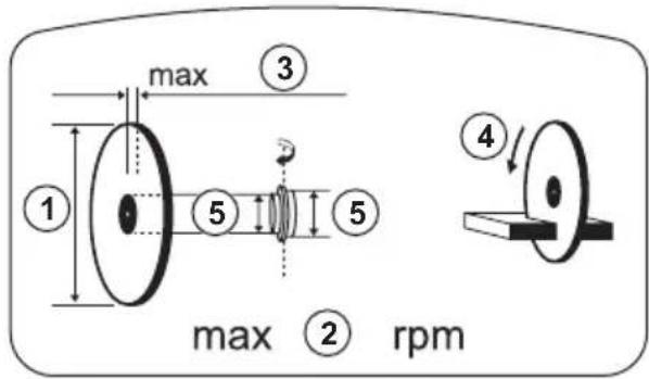
text_image
max ③ ① ⑤ ⑤ ④ max ② rpmRij 1: Merk, model (X, Y)
natural_image
Illustration of a person wearing full-body protective gear and a first aid kit (no text or symbols)text_image
Technical diagram of a mechanical assembly with labeled parts A and BGashendelvergrendeling controleren
- Controleer of de gashendel vergrendeld is in de stationaire stand wanneer de gashendelvergrendeling wordt losgelaten.
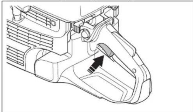
natural_image
Technical line drawing of a mechanical component with an arrow indicating a specific part (no text or symbols present)natural_image
Technical line drawing of a mechanical component with an arrow indicating a specific part (no text or symbols present)natural_image
Technical line drawing of a mechanical component with directional arrows indicating assembly or movement (no text or symbols present)text_image
Technical diagram showing a mechanical component with an inset highlighting a stop button labeled 'STOP'Bladbeschermkap en SmartGuard (optioneel)

text_image
Diagram of a car interior with labeled parts A, B, and C showing structural components.natural_image
Diagram of a car's steering wheel and dashboard with directional arrows indicating rotation (no text or symbols)natural_image
Three identical mechanical screw components shown in isometric view, no text or symbols presentTrillingsdempingssysteem controleren

natural_image
Technical line drawing of two interlocking gears with a shaded central section (no text or symbols)natural_image
Diagram of a geological cross-section showing layered strata with no text or symbolsnatural_image
Circular mechanical gear diagram with evenly spaced teeth and central bore (no text or symbols)natural_image
Diagram of a medical device with two circular components and directional arrows indicating movement or force (no text or symbols)natural_image
Simple line drawing of a globe with a black arrow pointing to it, next to a stylized 3D object (no text or symbols)text_image
Technical diagram illustrating gear meshing process with labeled components and directional arrowsnatural_image
Diagram of a mechanical device with rotating components and motion arrows (no text or symbols)text_image
Diagram of a mechanical device with labeled parts A, B, and C showing internal components and motion paths.natural_image
Line drawing of a mechanical device with a tool and circular component (no text or symbols)natural_image
Technical line drawing of a mechanical tool interacting with a cutting machine (no text or symbols)De zaagkop omkeren (K 1270 II)
natural_image
Mechanical assembly diagram showing a bracket with attached components and a close-up of the mechanism (no text or labels)natural_image
Technical illustration of a car brake system showing suspension components and motion arrows (no text or symbols)natural_image
Technical line drawing of a mechanical device with attached clips and a central component (no text or symbols)natural_image
Technical line drawing of a mechanical component with no visible text or symbolsnatural_image
Technical diagram of a mechanical component with directional arrows indicating motion (no text or labels)natural_image
Mechanical assembly diagram showing a wheel and bracket assembly with directional arrows (no text or labels)natural_image
Diagram showing a mechanical device interacting with a circular component, with directional arrows indicating motion (no text or symbols)text_image
Diagram illustrating safety hazard with a warning sign and circular hazard symbol, likely from an emergency or hazard context.Roterende terugslag
text_image
Safety instruction illustration showing a worker using a tool to clean air, with an inset diagram illustrating hazard zones.text_image
Safety warning illustration showing a worker with crossed-out hand signals and a hazard symbol on the gear mechanism.natural_image
Diagram of a medical procedure with a surgical tool and X mark symbol (no text or labels)text_image
Diagram illustrating a mechanical or robotic operation with labeled components and directional arrows indicating movement.natural_image
Simple line drawing of a device with a download icon and circular loading symbol (no text or labels)natural_image
Diagram showing a mechanical component interacting with a circular target, with arrows indicating motion or force direction (no text or symbols present)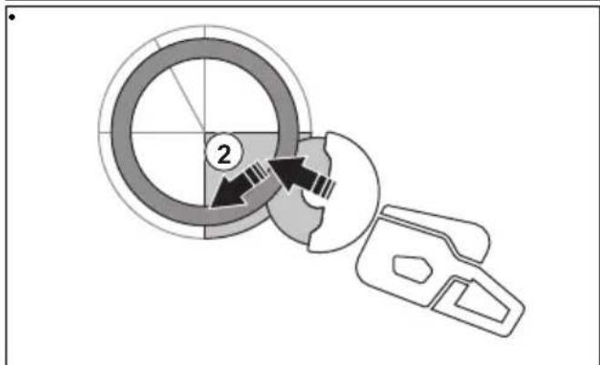
text_image
Diagram showing a mechanical or electrical component with labeled parts and directional arrows indicating motion or movement.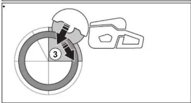
text_image
③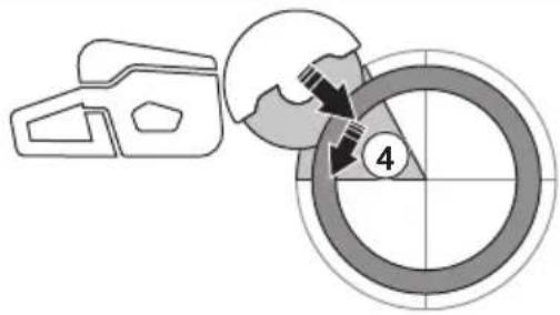
text_image
Diagram showing a mechanical assembly with labeled component '4' and directional arrows indicating motion or movement.natural_image
Symbolic illustration of crossed-out black arrows over a gray rectangular block, with no text or labels present.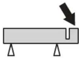
natural_image
Simple diagram of a beam with supports and a downward arrow indicating force or direction (no text or symbols)Basistechniek
natural_image
Line drawing of a person using a handheld device to interact with another person (no text or symbols present)text_image
Diagram illustrating a mechanical or electrical process with labeled components and directional arrows, including a crossed-out symbol.natural_image
Diagram of a mechanical device with a rotating shaft and base, showing motion direction (no text or symbols)text_image
Safety warning illustration showing two workers using a ladder to stop equipment, one with crossed-out X symbols and the other holding a helmet.natural_image
Line drawing of a person using a handheld tool on their lower legs (no text or symbols)natural_image
Diagram showing two mechanical components with a crossed-out cross symbol, no text or labels presentnatural_image
Line drawing of a person using a power saw to cut a saw (no text or symbols present)text_image
Safety warning illustration showing fuel injection and discharge symbols with a person holding a bottletext_image
Diagram showing eight different mechanical or electrical component symbols with labels such as thermometer, valve, 6x, and various directional arrows.
natural_image
Line drawing of a car gear shift lever with a black arrow pointing to the center (no text or symbols)- Controleer of de STOP-schakelaar in de linker stand staat.
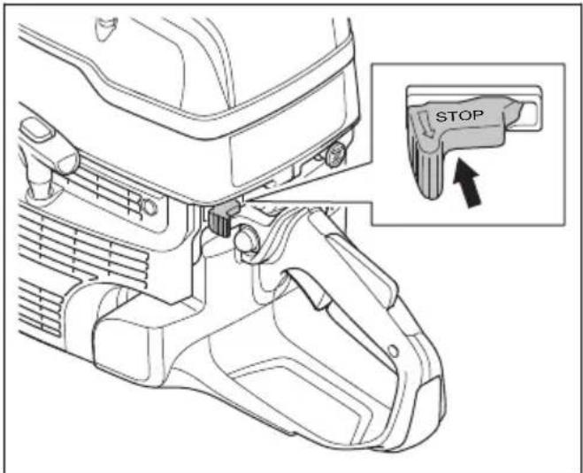
text_image
STOPnatural_image
Technical line drawing of a mechanical component with an inset showing a pin assembly (no text or symbols present)natural_image
Technical line drawing of a mechanical component with no visible text or symbolsnatural_image
Illustration of a worker in safety gear using a tool on a circular object (no text or symbols)
natural_image
Technical line drawing of a mechanical component with a magnified inset showing a pin inserted into a housing (no text or symbols present)natural_image
Technical line drawing of a mechanical component with directional arrows indicating movement or force (no text or symbols present)text_image
Diagram showing five different types of heating and cooling symbols with corresponding icons
natural_image
Line drawing of a car gear shift lever with a downward arrow indicating the direction (no text or symbols present)- Controleer of de STOP-schakelaar in de linker stand staat.
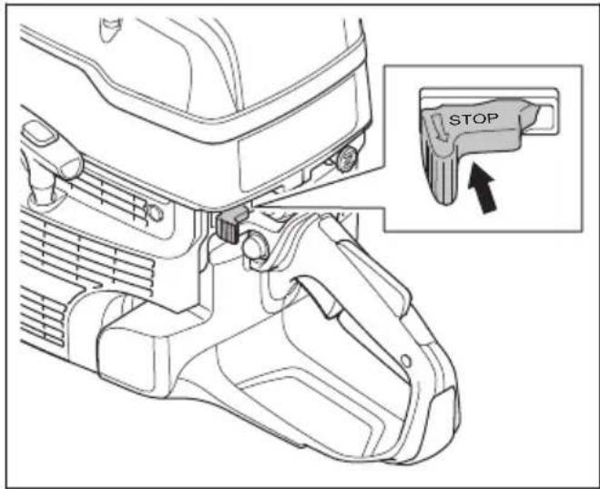
text_image
STOPnatural_image
Technical line drawing of a mechanical component with an inset showing a pin assembly (no text or symbols present)natural_image
Technical line drawing of a mechanical component with a highlighted insertion section (no text or symbols)natural_image
Illustration of a worker in safety gear handling equipment (no text or symbols)
natural_image
Technical line drawing of a mechanical component with directional arrows indicating movement or force (no text or symbols present)Product stoppen
text_image
Technical diagram showing a mechanical component with an inset highlighting a stop button labeled 'STOP'text_image
Safety warning illustration showing two workers in protective gear with a crossed-out 'X' symbol and fire extinguisher illustrationsnatural_image
Mechanical clamp device with lever mechanism and directional arrow (no text or symbols)natural_image
Technical line drawing of a mechanical clamp and wheel assembly (no text or symbols)natural_image
Technical line drawing of a mechanical cutting tool with a circular blade and lever mechanism (no text or symbols)natural_image
Diagram showing a mechanical device interacting with a base, with directional arrows indicating movement (no text or symbols present)- De rail doorzagen.

text_image
Diagram illustrating three stages of railway track installation: initial setup, sequential assembly, and final completion.natural_image
Technical line drawing of a mechanical clamp or clamping device with a hand operating it (no text or symbols present)natural_image
Technical illustration of a hand operating a mechanical device with a close-up inset showing the left side (no text or symbols present)natural_image
Three abstract line drawings showing different mechanical or structural configurations (no text or symbols)natural_image
Technical diagram of a car interior showing airflow or heat distribution in a vehicle (no text or symbols)natural_image
Diagram of a car interior showing dashboard, intake manifold, and air vent (no text or labels)text_image
Diagram illustrating car interior cleaning steps with labeled icons and checkmark/unknown indicatorstext_image
Technical diagram illustrating engine component assembly steps with labeled parts and directional arrowsnatural_image
Line drawing of a mechanical device with a tool and base (no text or symbols)text_image
Technical diagram of a mechanical assembly with labeled parts A and B, showing directional arrows and component alignment.natural_image
Technical line drawing of a mechanical assembly with no visible text or symbolsnatural_image
Technical line drawing of a mechanical assembly with directional arrows indicating motion or force (no text or symbols)text_image
Technical diagram showing car wheel assembly with labeled parts and directional arrows indicating assembly stepsnatural_image
Technical line drawing of a mechanical assembly with no visible text or symbolsnatural_image
Technical line drawing of a car's internal components and suspension system (no text or symbols)natural_image
Technical line drawing of a mechanical device with gear and mounting bracket, showing internal components and a close-up inset (no text or symbols)natural_image
Technical line drawing of a mechanical tool or saw cutting process, showing blade and handle assembly (no text or symbols)text_image
Technical diagram illustrating mechanical assembly with labeled parts A and B, showing gear shift and valve mechanism.natural_image
Technical diagram of a vehicle engine showing intake manifold, fan blade, and gear assembly (no text or labels)text_image
Technical diagram of a mechanical device with labeled parts A, B, and C, showing internal components and directional arrows.natural_image
Technical diagram of a mechanical assembly showing internal components and directional arrows (no text or labels)natural_image
Technical illustration of a mechanical assembly with a hand holding a tool, showing internal components and a downward arrow (no text or symbols)natural_image
Technical line drawing of a mechanical device with a hand operating the shaft and a black arrow indicating a downward motion (no text or symbols present)text_image
Diagram illustrating cable installation steps with labeled components A, B, and C, showing cable routing from a vehicle chassis.natural_image
Technical diagram of a mechanical device with internal components and directional arrows indicating flow or movement (no text or labels)text_image
Technical diagram of an air duct system with labeled components and directional arrows indicating flow or movement.text_image
Diagram showing car tire mounting technique with labeled parts A and B, including rope knot and cable assemblynatural_image
Technical line drawing of a mechanical device showing internal components and airflow paths (no text or symbols)text_image
Technical diagram of a mechanical device with labeled parts A, B, and C showing internal components and assembly steps.text_image
Technical diagram of a mechanical device with labeled parts A and B, showing internal components and directional arrows.natural_image
Technical diagram of a mechanical assembly with exploded view and close-up views (no text or labels)natural_image
Technical line drawing of a mechanical assembly with a tool inserted, showing internal components and a black arrow indicating a specific part (no text or symbols present)natural_image
Technical line drawing of a mechanical assembly with no visible text or symbolstext_image
Technical diagram of a medical device with labeled parts A and B, showing ear anatomy and surgical hardware.natural_image
Technical line drawing of a mechanical device with gear and adjustment arrows (no text or symbols)natural_image
Technical line drawing of a mechanical assembly with a central component and an arrow indicating direction (no text or symbols present)
text_image
Diagram illustrating a mechanical device with an inset showing a component being lifted, accompanied by a prohibition symbol.natural_image
Technical line drawing of a mechanical component with threaded end and shaft (no text or symbols)text_image
Safety warning illustration showing two workers in protective gear holding fire extinguishers, one marked with a crossed-out X symbol.natural_image
Mechanical assembly diagram showing linkage components with an upward arrow indicating motion (no text or labels)Zaagwagen
natural_image
Line drawing of a mechanical power tool with wheels and a central housing (no text or symbols)Original instructions
Originalanweisungen