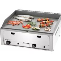
GDP 650GG - Grill plate BARTSCHER - Free user manual and instructions
Find the device manual for free GDP 650GG BARTSCHER in PDF.



| Product type | Professional gas grill plate |
| Brand | Bartscher |
| Model | GDP 650GG |
| Number of burners | 2 |
| Total power | 8.0 kW (2 x 4.0 kW) |
| Plate dimensions | 65 x 48 cm |
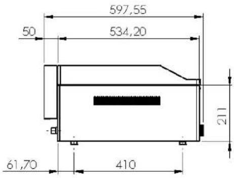
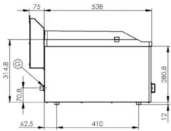
| Overall dimensions (L x D x H) | 66 x 60 x 22 cm |
| Approximate weight | 25 kg |
| Power supply | Gas (butane/propane 28-30 mbar, propane 37 mbar, natural gas 20 mbar) |
| Plate material | Stainless steel |
| Ignition type | Piezoelectric |
| Safety | Safety thermocouple (automatic gas shut-off if flame goes out) |
| Grease container | Integrated, removable |
| Power setting | Minimum (economical) and maximum |
| Usage | Professional, kitchen use |
| Installation | On horizontal surface, under hood, minimum distance 10 cm from flammable walls |
| Daily maintenance | Clean with a damp cloth and non-abrasive detergent, rinse and dry |
| Spare parts available | Nozzles, piezoelectric electrode, thermal probe, knobs, etc. |
| Repairability | Interventions reserved for qualified technician |
| Recommended inspection frequency | At least once a year by a specialized service |
Frequently Asked Questions - GDP 650GG BARTSCHER
User questions about GDP 650GG BARTSCHER
0 question about this device. Answer the ones you know or ask your own.
Ask a new question about this device
Download the instructions for your Grill plate in PDF format for free! Find your manual GDP 650GG - BARTSCHER and take your electronic device back in hand. On this page are published all the documents necessary for the use of your device. GDP 650GG by BARTSCHER.
USER MANUAL GDP 650GG BARTSCHER
INSTRUCTIONS FOR INSTALLATION AND USE
DIE GEBRAUCHS- UND INSTALLATIONSANWEISUNG NOTICE D'INSTALLATION ET D'EMPLOI
natural_image
Exterior view of a stainless steel gas stove with two red pressure gauges (no text or symbols visible)
natural_image
Exterior view of a stainless steel portable kitchen appliance with two side handles and a front panel (no text or symbols visible)FTH - 30G, GL / A3700331
FTR - 30G, GL
FTH - 60G, GL / A3700341
FTHR - 60G, GL
FTH - 90G, GL
FTHC - 30G, GL
FTRC - 30G, GL
FTHC - 60G, GL
FTHRC - 60G, GL
FTHC - 90G, GL

CONTENT 3
DECLARATION OF A STANDARDS CONFORMITY
INSTRUCTION FOR USE
CLEANING AND MAINTENANCE

DÉCLARATION DE CONFORMITÉ
MODE D'EMPLOI
ENTRETIEN
DECLARATION OF A STANDARDS CONFORMITY
The producer confirms that the devices agree with 2009/142/ES standards, rule nr. 22/1997 sb., nr. 258/2000 sb.. nr. 258/200 sb. and with relevant government orders. Instalation must be done with respect to valid standards. Attention, the producer refuses any responsibility in case of direct or indirect damages which are caused due to wrong instalation, incorrect intervention or modification, insufficient maintenance, incorrect use and also possibly caused by other reasons presented by items in sale conditions. This appliance is set only for skilled use and must be operated by qualified persons only. Parts set and secured by the producer or accredited person must not be rebuilt by user.
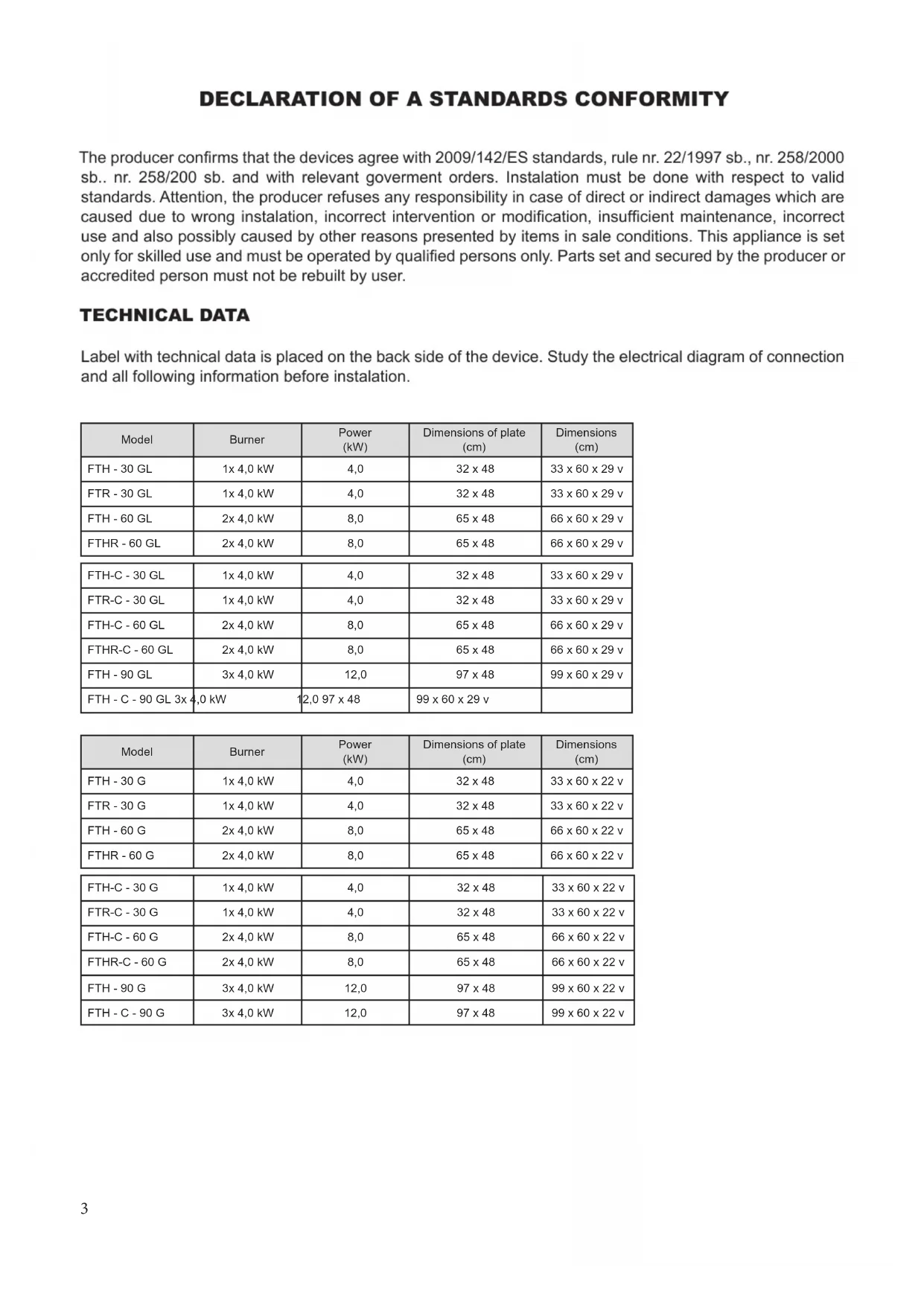
TECHNICAL DATA
Label with technical data is placed on the back side of the device. Study the electrical diagram of connection and all following information before installation.
| Model | Burner | Power (kW) | Dimensions of plate (cm) | Dimensions (cm) |
| FTH - 30 GL | 1x 4,0 kW | 4,0 | 32 x 48 | 33 x 60 x 29 v |
| FTR - 30 GL | 1x 4,0 kW | 4,0 | 32 x 48 | 33 x 60 x 29 v |
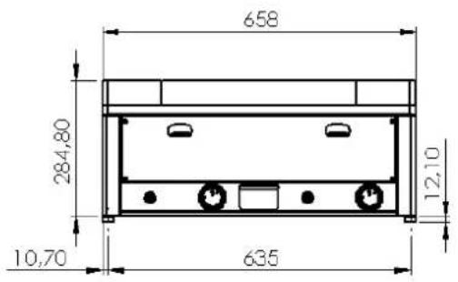
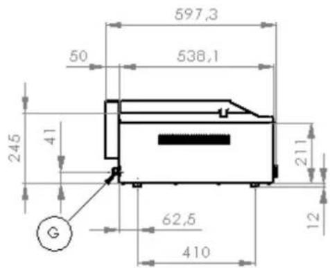
| FTH - 60 GL | 2x 4,0 kW | 8,0 | 65 x 48 | 66 x 60 x 29 v |
| FTHR - 60 GL | 2x 4,0 kW | 8,0 | 65 x 48 | 66 x 60 x 29 v |
| FTH-C - 30 GL | 1x 4,0 kW | 4,0 | 32 x 48 | 33 x 60 x 29 v |
| FTR-C - 30 GL | 1x 4,0 kW | 4,0 | 32 x 48 | 33 x 60 x 29 v |
| FTH-C - 60 GL | 2x 4,0 kW | 8,0 | 65 x 48 | 66 x 60 x 29 v |
| FTHR-C - 60 GL | 2x 4,0 kW | 8,0 | 65 x 48 | 66 x 60 x 29 v |
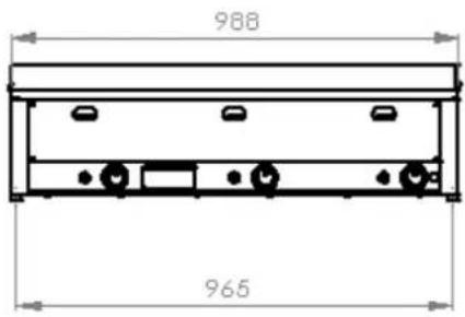
| FTH - 90 GL | 3x 4,0 kW | 12,0 | 97 x 48 | 99 x 60 x 29 v |
| FTH - C - 90 GL 3x 4,0 kW | 12,0 97 x 48 | 99 x 60 x 29 v | ||
| Model | Burner | Power (kW) | Dimensions of plate (cm) | Dimensions (cm) |
| FTH - 30 G | 1x 4,0 kW | 4,0 | 32 x 48 | 33 x 60 x 22 v |
| FTR - 30 G | 1x 4,0 kW | 4,0 | 32 x 48 | 33 x 60 x 22 v |
| FTH - 60 G | 2x 4,0 kW | 8,0 | 65 x 48 | 66 x 60 x 22 v |
| FTHR - 60 G | 2x 4,0 kW | 8,0 | 65 x 48 | 66 x 60 x 22 v |
| FTH-C - 30 G | 1x 4,0 kW | 4,0 | 32 x 48 | 33 x 60 x 22 v |
| FTR-C - 30 G | 1x 4,0 kW | 4,0 | 32 x 48 | 33 x 60 x 22 v |
| FTH-C - 60 G | 2x 4,0 kW | 8,0 | 65 x 48 | 66 x 60 x 22 v |
| FTHR-C - 60 G | 2x 4,0 kW | 8,0 | 65 x 48 | 66 x 60 x 22 v |
| FTH - 90 G | 3x 4,0 kW | 12,0 | 97 x 48 | 99 x 60 x 22 v |
| FTH - C - 90 G | 3x 4,0 kW | 12,0 | 97 x 48 | 99 x 60 x 22 v |
BURNERS
| MODEL NOZZLE Burner | 12,8 kWh/kgG 30/G 31PROPAN / BUTAN28 - 30 mbar | 12,8 kWh/kgG 31PROPAN37 mbar | 12,8 kWh/kgG 30/G 31PROPAN / BUTAN50 mbar | 9,45 kWh/m ^3 G 20Natural GAS20 mbar | FEEDING TUBE GAS | |
| FT**-30 | NOZZLE OF BURNER 1/100 MM 4,0 kW 93 93 77 | 135 G 1/2" | ||||
| CONSUPTION | 4,0 kW | 0,546 kg/h | 0,546 kg/h | 0,546 kg/h | --- | |
| FT**-60 | NOZZLE OF BURNER 1/100 MM | 2x 4,0 kW | 93 93 77 135 G 1/2" | |||
| CONSUPTION | 2x 4,0 kW | 1,092 kg/h | 1,092 kg/h | 1,092 kg/h | --- | |
| FT**-90 | NOZZLE OF BURNER 1/100 MM | 3x 4,0 kW | 93 93 77 135 G 1/2" | |||
| CONSUPTION | 3x 4,0 kW | 1,638 kg/h | 1,638 kg/h | 1,638 kg/h | --- |
PACKING AND DEVICE CHECK
The device leaves our stocks properly packed with appropriate symbols and labels. There are also appropriate instructions for use. In case the packing shows bad handling or damage, it must be reclaimed at transporter immediately by writing and signing of a damage protocol.
Important notice:
- this instructing guide must be read properly and carefully because it contains important information about safety elements, installation, use
• these recommendations refer to this product - this product corresponds with valid standards
- this guide must be properly deposited for future use
- keep the children away from manipulation with the product
- when selling or moving the product to another place it is necessary top make yourself sure that the staff or the professional service has got acquainted with control and installation instructions from enclosed guide
- only authorised person can operate the product
- it can not be switched on without supervision
• we recommend to have the product checked by professional service min. once a year - only original spare parts can be used for repairs
- the product can not be cleaned by the water jet or pressure shower
- by damage or break down disconnect all the feeders (water, gas, electricity) and call professional service
- producer refuses any responsibility in case of damages caused by wrong installation, by disobserving of above mentioned recommendations or by other use etc.
PLACEMENT
The device must be installed in well ventilated room what is necessary for regulation of the function of the device (technician must go by valid standard (ČSN....). If the device is situated close to the wall or if it is in contact with the furniture walls, these walls must resist the temperatures ranging to 60°C. Installation, setting, putting into operation must be done by qualified person who is competent for this and according to the valid standards.
Wrap up the device and check whether it was not damaged during transport. Settle the device on horizontal surface (max imbalance 2°). Settle the device under the fumehood to eliminate water steam and bad smell. The device can be instalated separately or in a set with devices of our production. Min. distance 10 cm from other subjects must be kept. It is also necessary to prevent our product from contact with combustible materials. In this case you must make corresponding changes to secure heat izolation of combustible parts. Safety measures from the standpoint of the fi re protection according to ČSN 061008čl. 21:
DEVICE INSTALATION
Instalation, setting, rebuilding for another gas type, putting into operation must be done by qualified person who is competent for this and according to the valid standards. The device can be installed in good ventilated room. When it is possible place the device under the fumehood to suck off the products of combustion. Air needy to the burning is 2m/3/h/kW of the performance of the instaled device.
The device can be instalated separately or in a set with devices of our production. Min. distance 10 cm from other subjects must be kept. It is also necessary to prevent our product from contact with combustible materials. In this case you must make corresponding changes to secure heat izolation of combustible parts (for example: place between the device and combustible material azbestos plate).
SAFETY MEASURES FROM THE STANDPOINT OF THE FIRE PROTECTION ACCORDING TO EN 061008 ČL. 21
- only adults can operate the device
• device must be safely used in common surroundings according to EN 332000-4-482; EN 332000-4-42 - device must be placed so as to stand or hang on the noncombustible surface. No subjects from combustible materials can be placed directly on the device or in distance which is shorter than safety distance (the shortest distance is 10 cm).
- safety distances from various materials of different degree of combustion and information about the degree of comb. of common building materials - see chart:
Chart:
Combustion degree of building materials classified according to the combustion degree of materials and products (EN 730823)
A noncombustible granit, sandstone, concretes, bricks, ceramic wallfacing tiles, plaster
B uneasily combustible akumine, heraklite, lihnos, itavere
C1 hardly combustible leafy wood, plywood, sirkoklit, rare paper formica
C2 middle combustible fi breboards, solodure, cork boards, rubber, fl oor-coverings
C3 easily combustible wood-fi breboards, polystyrene,polyurethane, PVC
Devices must be installed in a safe way. When installing you must respect corresponding project, safety and hygienic orders according to:
• EN 061008 fire protection of local devices and sources of heat
• EN 332000 surrounding for electric devices
PIPE FOR GAS CONNECTION
It must first determine if the appliance is made for the same type of gas that will be used and thus conforms to the indications on the label the type of gas to be used.
The conversion of gas pan to another type of gas you need to check if it corresponds to the type of gas bearing, which is recommended in this guide.
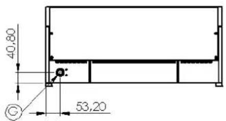
Connecting the appliance to the gas distribution must be towable to a steel or copper tube complying with applicable national requirements. This must be controlled on regular basis and changed if needed. Every appliance must be equipped with shut-off valve and quick shut-off valve. Quick shut-off valve must be freely accessible and within reach of the device. After installation, is necessary to check whether there is a gas leak. To find a gas leak you can use soapy water or spray for gas leak detection.
Do not use corrosive substances!! All our appliances are carefully controlled. Gas type, pressure and of the categories listed named on the technical information plate.
Liquid gas connection:
Pressure for liquid gas connection must be 28 or 30 mbar for propane/butane and 37 mbar for propane. It is necessary to check the technical label, gauge the pressure and check the parameters of the nozzle is installed with the required parameters of the nozzle according to the manufacturer's. If the pressure is lower than 25mbar or higher than 37 mbar, THE APPLIANCE SHALL NOT TO BE CONNECTED.
Gas Connection:
Pressure for methane connection must be 18 or 20 mbar. It is necessary to check the technical label ,gauge the pressure and check the parameters of the nozzle is installed with the required parameters of the nozzle according to the manufacturer's. If the gas pressure is lower than 15mbar or higher than 22,5 mbar, THE APPLIANCE SHALL NOT TO BE CONNECTED.
Instructions for sucking off the gas products of combustion
Type A devices (see the label with characteristics). Appliance of fi nish A, that is the appliance which is not made for being connected with the chimney or other device for sucking off the products of combustion out of the space where the appliance is situated. These appliances must be situated in the room with suffi cient ventilation according to the ČSN 12 7010:1986 and ČSN 1207040:1986. It is necessary to prevent the accumulation of the harmful matters in big concentration (secure the requirement of hygienic standard for working surrounding sv. 39/78 guideline 46).
CHECK THE GAS TYPE THE DEVICE IS ADJUSTED FOR
Check whether the device is set for the gas type you use. The gas type is indicated on the label of each device.
Process of rebuilding the device for another gas type
The device is set and checked for liquefi ed gas (see the label). Rebuilding for another gas type must be done by qualified person. Nozzles are included in the packet with instructions for use.
Exchange of the main burner's nozzle: picture D
Screw up and remove the bottom cover (21), screw up the nozzle (23a) and screw in the new one for required gas type - see technical chart. You need not to regulate air feeder.
Important:
After having rebuilt the gas type, change the data on the label.
How to check the operation of the device:
- check the gas leaks
- check the ignition and flame of the main burner
- check the ignition and flame of the main burner for min. performance (sporo)
- check whether the flame of the burner licks the thermoelement and whether it is blue
- we recommend to the user when using the device to proceed according to the instructions for use
Regulation of the flame by the lower performance (sporo):
Adjust the low performance (sporo) and then regulate the flame with screw which is situated in the body of the tap next to the tap shaft.
Process of regulation:
- remove the regulation tap knob (pull to yourself)
- there is slot for regulation next to the tap shaft
• regulate the flame with the small fl at screwer
Maintenance:
We recommend you to have the device checked once a year by professional service. Only qualified or competent persons can do interventions in the product.
It may be necessary to exchange some parts during the useful life of the device:
piezzo electrode, sensor of the thermofuse
Exchange of the piezzo electrode or thermofuse sensor: picture D
Screw up and remove the bottom cover (17), screw up the holder of the electrode and the sensor (26), disconnect and remove the electrode (27) or sensor (23). The fitting up of new part must be done in the contrary.
INSTRUCTION FOR USE
Attention!
When the hot-plate smokes after the first switching it on it is necessary to leave the device on at least for an hour until the smoke disappears.
- Ignition of the main burner and regulation of the temperature: pictures A,B
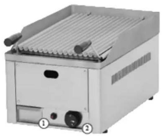
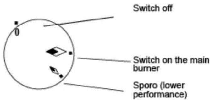
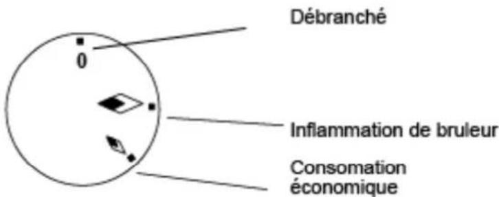
Turn the regulation knob (2) into position "ignition of the main burner" and then press it down and hold it. Press down the piezo knob of the ignitor several times (1) until the main burner burns. The flame is visible through the slot in the front panel. After ignition of the burner hold the knob (2) pressed several seconds till the thermofuse gets hot. Then release the button. If the flame goes out repeat the whole process once more.
- Lower performance sporo: picture A.B
By turning the knob (2) into position „sporo“ you set the burning of the burner for sporo (lower performance).
• How to switch the whole device off: picture A,B
Turn the knob (2) into position "0".
Bowl for superfluous oil
Check this bowl regularly and empty it in time. You must clean the bowl after each switching the device off. ATTENTION! THIS BOWL CAN BE HOT WHEN THE DEVICE IS ON. EMPTY IT WHEN THE DEVICE IS COLD.
natural_image
Exterior view of a gas grating machine with two labeled ports (① and ②), no visible text or symbols on the device itself.① Piezzo knob
② Regulation knob
LEANING AND MAINTENANCE
Clean the device daily. Stainless parts wash with moist cleaning cloth and detergent without groove parts then splash it with clean water and dry it by the cloth. When cleaning the interior space, the burner can be removed ( lift the back part and by back work movement back out from frot brackets After cleaning impregnate the surface of the hot-plates with oil.
WHAT TO DO IN CASE OF BREAK-DOWN?
Switch off the gas feeder and call seller's professional service.
The way of usage and liquidation of the litter
Wrapping - sell it to the salvage. Wrapping foil - give into the salvage containers for plastic. Liquidation of the device after useful life: „Sell the device and it’s parts to the salvage.“
INDICATION
Guarantee does not cover all consumption parts succumable to common wear (rubber seals, bulbs, glas and plastic parts etc.). The guarantee does not refer to the devices which were not installed in correspondence with instructions - by qualified worker, in confirmity with standards and when somebody handled incompetently the device (interventions into inner equipment) or the device was operated by nonqualified staff or at variance with instructions for use. Guarantee does not also cover the damages caused due to influence of nature or other outer intervention.
natural_image
Exterior view of a stainless steel grater with cooling fins and control buttons (no text or symbols visible)DÉCLARATION DE CONFORMITÉ
natural_image
Exterior view of a stainless steel grating machine (no visible text or symbols)① Piezzo
② Bouton
FT** 60 G
FT** 90 G
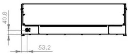
FT** 30 GL
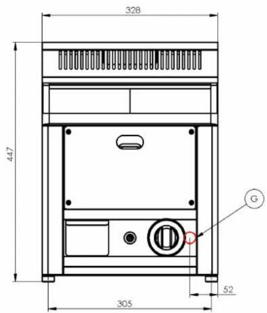
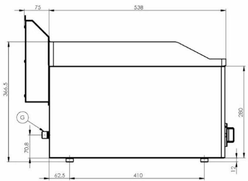
FT** 90 GL
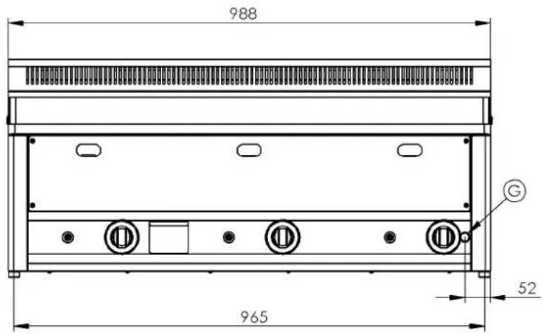
- INSTRUCTIONS FOR INSTALLATION AND USE
- CONTENT 3
- DECLARATION OF A STANDARDS CONFORMITY
- TECHNICAL DATA
- PACKING AND DEVICE CHECK
- Important notice:
- PLACEMENT
- DEVICE INSTALATION
- SAFETY MEASURES FROM THE STANDPOINT OF THE FIRE PROTECTION ACCORDING TO EN 061008 ČL. 21
- Chart:
- PIPE FOR GAS CONNECTION
- Liquid gas connection:
- Gas Connection:
- Instructions for sucking off the gas products of combustion
- CHECK THE GAS TYPE THE DEVICE IS ADJUSTED FOR
- Process of rebuilding the device for another gas type
- Exchange of the main burner's nozzle: picture D
- Important:
- How to check the operation of the device:
- Regulation of the flame by the lower performance (sporo):
- Maintenance:
- Exchange of the piezzo electrode or thermofuse sensor: picture D
- INSTRUCTION FOR USE
- Attention!
- Bowl for superfluous oil
- LEANING AND MAINTENANCE
- WHAT TO DO IN CASE OF BREAK-DOWN?
- The way of usage and liquidation of the litter
- INDICATION
- DÉCLARATION DE CONFORMITÉ
Brand : BARTSCHER
Model : GDP 650GG
Category : Grill plate