CMS 403DCE - Speaker TANNOY - Free user manual and instructions
Find the device manual for free CMS 403DCE TANNOY in PDF.
Download the instructions for your Speaker in PDF format for free! Find your manual CMS 403DCE - TANNOY and take your electronic device back in hand. On this page are published all the documents necessary for the use of your device. CMS 403DCE by TANNOY.
USER MANUAL CMS 403DCE TANNOY
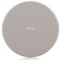
4" Full Range Ceiling Loudspeaker with Dual Concentric or ICT Driver and adjustable “eyeball” design V 1.02 CMS 3.0 Series Quick Start Guide 3 (EN) Safety Instruction
1. Read these instructions.
2. Keep these instructions.
3. Heed all warnings.
4. Follow all instructions.
5. Do not use this apparatus near water.
6. Clean only with dry cloth.
7. Do not block any ventilation openings. Install in
accordance with the manufacturer’s instructions.
8. Do not install near any heat sources such
as radiators, heat registers, stoves, or other apparatus (including ampliers) that produce heat.
9. Use only attachments/accessories specied
by the manufacturer.
the cart, stand, tripod, bracket, or table specied by the manufacturer, or sold with the apparatus. When a cart is used, use caution when moving the cart/apparatus combination to avoid injury from tip-over.
11. Correct disposal of this
product: This symbol indicates that this product must not be disposed of with household waste, according to the WEEE Directive (2012/19/EU) and your national law. This product should be taken to a collection center licensed for the recycling of waste electrical and electronic equipment (EEE). The mishandling of this type of waste could have a possible negative impact on the environment and human health due to potentially hazardous substances that are generally associated with EEE. At the same time, your cooperation in the correct disposal of this product will contribute to the ecient use of natural resources. For more information about where you can take your waste equipment for recycling, please contact your local city oce, or your household waste collection service.
12. Do not install in a conned space, such as a
book case or similar unit.
13. Do not place naked ame sources, such as lighted
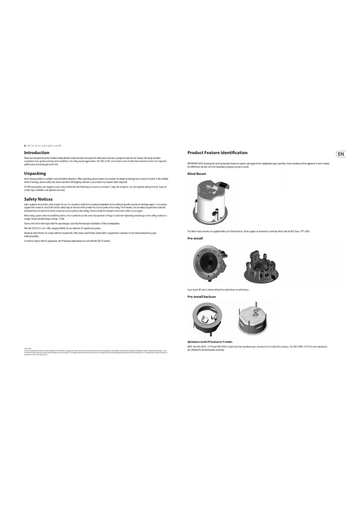
takich jak zapalone świece.6 CMS 3.0 Series Quick Start Guide 7 Product Feature Identication IMPORTANT NOTE: Drawings for each loudspeaker below are generic and apply to the loudspeaker types specified. Some variations will be apparent in some models, but differences are not critical for installation purposes except as noted. Blind Mount The blind-mount models are supplied with a pre-fitted backcan. Above applies to all models as well any others that do NOT have a “PI” suffix. Pre-install A pre-install (PI) unit is shown without the optional pre-install backcan. Pre-install backcan Optional pre-install (PI) backcan for PI models. NOTE: The CMS 603DC / ICT PI and CMS 803DC models have the transformer pre-attached to the inside of the backcan. The CMS 503DC / ICT PI has the transformer pre-attached to the loudspeaker assembly. Introduction Thank you for purchasing this Tannoy Ceiling Monitor System product. Designed for both speech and music program material, the Tannoy CMS range provides exceptional sonic quality and long-term reliability in all ceiling mount applications. The CMS 3.0 DC series features new 16 ohm Dual Concentric drivers for improved performance and prolonged service life. Unpacking Every Tannoy product is carefully inspected before shipment. After unpacking, please inspect your product to ensure no damage has occurred in transit. In the unlikely event of damage, please notify your dealer and retain all shipping materials as your dealer may require return shipment. All CMS loudspeakers are shipped in pairs and provided with the following accessories as standard: C-ring, tile-bridge kit, cut-out template and paint mask. A plaster (mud) ring is available as an optional accessory. Safety Notices Some regional construction codes require the use of a secondary method of securing loudspeakers in the ceiling to provide security of a backup support. A secondary support line should be attached from the safety loop on the rear of the product to a source point on the ceiling. For PI models, the secondary support line should be attached from the back of the driver chassis to a source point on the ceiling. Please consult the relevant construction codes in your region. When using a power driver to install the product, it is essential to use the correct torque level settings to avoid over-tightening and damage to the ceiling material or clamps. Recommended torque setting: 1.5 Nm Tannoy will not be held responsible for any damages caused by the improper installation of these loudspeakers. The CMS 603 ICT LS is UL-1480, category UUMW, for use with non-DC supervised systems. Electrical Safety Notice: To comply with the standard UL-1480, metal-clad flexible conduit (BX) is required for connection to the terminal block for proper earth grounding. In order to comply with UL regulations, the PI backcan must always be used with the CMS PI models. SAFETY NOTE: In order to comply with the relevant re safety regulations (ie. BS 5839:1998), it is required that in the event of re, that failure of the circuit to which the loudspeaker is connected does not occur before evacuation of the building is complete. Suitable measures include: - a) use of terminal blocks (for connection to primary) with a melting point of not less than 650°C, for example constructed from ceramic materials; b) use of terminal blocks of a lower melting point but protected with thermal insulation;c) use of terminal blocks such that, on melting, an open-circuit or a short-circuit does not occur.8 CMS 3.0 Series Quick Start Guide 9 Accessories Standard Accessories Optional Accessories
C-Ring Grille Paint Mask Cut-out template Tile-bridge kit Note: A tile-bridge kit must always be used when installing into suspended ceiling tiles
1. Remove the ceiling tile from its frame and place it on a at surface. Position the cutout template
(self adhesive backed) on the tile. (Fig.1)
2. Cut out the hole in the ceiling tile using a pad saw following the broken line indicated on the template (Fig.2)
3. Place the C-Ring and tile-bridge on top of the ceiling panel, aligning the C-Ring over the hole, and screw the
C-Ring to the tile bridge using the xings provided. (Fig.3)
4. Go to the ‘Wiring and Setting Up’ chapter.
5. Slide the speaker assembly through the hole. Turn the screws (denoted “Screw Fix”) clockwise on the front of
the speaker to extend the mounting wings. Tighten the screws until a rm grip is achieved. (NOTE: Screws have a PoziDriv head; use of a PoziDriv driver is recommended). If using a power driver, Tannoy recommends a torque setting of 1.5 Nm. (Fig.4) DO NOT OVERTIGHTEN!
6. Attach the nylon safety to the hooks on the front bae before attaching the grille by presenting it to the
speakers and allowing the magnets to pull it into position (Fig.5). (With the CMS 403DCe/ICTe, the grille is already tted to the product.) NOTE ON INSTALLATION OF CMS 403DCe/ICTe: Before tightening the screws in step 5, swivel the speaker in the desired direction. When the screws are tightened, the speaker will lock into position. Replace the front trim to conceal the mounting screws. Fig.1 Fig.2 Fig.3 Fig.4 Fig.510 CMS 3.0 Series Quick Start Guide 11 Installation Guide for Sheetrock (Plasterboard) Ceilings
1. Position the cutout template (self adhesive backed) on the ceiling. (Fig.1)
2. Cut out the hole in the ceiling using a pad saw following the broken line indicated on the template then slide the
C-Ring into the ceiling, aligning it over the cut-out hole. (Fig.2)
3. Go to the ‘Wiring and Setting Up’ chapter, then return to point 4 below.
4. Slide the speaker assembly through the hole. Turn the screws (denoted “Screw Fix”) clockwise on the front of
the speaker to extend the mounting wings. Tighten the screws until a rm grip is achieved. (NOTE: Screws have a PoziDriv head; use of a PoziDriv driver is recommended). If using a power driver, Tannoy recommends a torque setting of 1.5 Nm. (Fig.3) DO NOT OVERTIGHTEN!
5. Attach the nylon safety to the hooks on the front bae before attaching the grille by presenting it to the speakers
and allowing the magnets to pull it into position (Fig.4). (With the CMS 403DCe/ICTe, the grille is already tted to the product.) NOTE ON INSTALLATION OF CMS 403DCe/ICTe: Before tightening the screws in step 4, swivel the speaker in the desired direction. When the screws are tightened, the speaker will lock into position. Replace the front trim to conceal the mounting screws. Fig.1 Fig.2 Fig.3 Fig.4 Installation Guide for Optional Plaster Ring An optional plaster (mud) ring bracket is available from Tannoy. This bracket is designed to be pre-installed into newly constructed, non-suspended ceilings.
1. Nail or screw the plaster ring to the joists. (Fig.1)
2. Lay the speaker wiring to where the speaker will be tted and complete the plastering work on the ceiling. (Fig.2)
3. Go to the ‘Wiring and Setting Up’ chapter, then return to point 4 below.
4. Slide the speaker assembly through the hole. Turn the screws (denoted “Screw Fix”) clockwise on the front of
the speaker to extend the mounting wings. Tighten the screws until a rm grip is achieved. (Note: Screws have a PoziDriv head; use of a PoziDriv driver is recommended). If using a power driver, Tannoy recommends a torque setting of 1.5 Nm. (Fig.3) DO NOT OVERTIGHTEN!
5. Attach the nylon safety to the hooks on the front bae before attaching the grille by presenting it to the speakers
and allowing the magnets to pull it into position (Fig.4). (With the CMS 403DCe/ICTe, the grille is already tted to the product.) NOTE ON INSTALLATION OF CMS 403DCe/ICTe: Before tightening the screws in step 4, swivel the speaker in the desired direction. When the screws are tightened, the speaker will lock into position. Replace the front trim to conceal the mounting screws. Fig.1 Fig.2 Fig.3 Fig.412 CMS 3.0 Series Quick Start Guide 13 Installation Guide for Optional Pre-Installation Backcan (PI Models Only) An optional pre-install backcan is available for all pre-install (PI) models. The backcan is designed for pre-installation in newly constructed, non-suspended ceilings. NOTE: The CMS 603DC/ICT and CMS 803DC models have the transformer pre-attached to the inside of the backcan; the CMS 503DC/ICT models have the transformer pre-attached to the loudspeaker assembly.
1. Attach the backcan to a safe and secure xing point. This can be done in a number of ways:
METHOD 1: Fix the backcan to a secure fixing point by using suitable fixings with the 4 fixing holes provided on the PI backcan. (Fig.1) METHOD 2: Secure the backcan to a safe and secure fixing point using suitable fixings with the flexible straps that are attached to the PI backcan. (Fig.2) METHOD 3: a. Attach the PI backcan to the optional pre-mount ring (plaster ring) using the fixings provided with the pre-mount ring. (Fig.3) b. Next, secure the wings of the pre-mount ring to a safe and secure fixing point by using suitable fixings. (Fig.4) Please turn over Fig.1 Fig.2 Fig.3 Fig.4 Installation Guide for Optional Pre-Installation Backcan (PI Models Only)
2. Attach the conduit to the installed backcan. This can be done in two ways:
METHOD 1: You can use the clamp at the back of the pre-install backcan. The product will accept a squeeze connector with a thread size of up to 22 mm: To remove the cable clamp, simply unscrew the threaded washer (under the wiring cover) which holds the cable clamp in place and replace it with a conduit squeeze connector. (Fig.5) METHOD 2: You can use any of the three knock-out points at the sides of the PI backcan (19 mm, 22 mm or 28 mm diameter). (Fig.6)
3. If conduit is not chosen as the wiring method, run an approved speaker cable to the installed can.
Terminate in the top mounted cable clamp or with an approved cable connector in one of the three knock-out points at the sides of the PI backcan.
4. Cut hole in the proper location in the ceiling using a pad saw. Place the pre-install backcan over the
hole. (Fig.7) Conduit Conduit Squeeze Connector Fig.5 Fig.6 Fig.714 CMS 3.0 Series Quick Start Guide 15
5. Go to the ‘Wiring and Setting Up’ chapter, then return to point 6 below.
6. Slide the speaker assembly through the hole. Turn the screws (denoted “Screw Fix”) clockwise on the front of
the speaker to extend the mounting wings. Tighten the screws until a rm grip is achieved. (NOTE: Screws have a PoziDriv head; use of a PoziDriv driver is recommended). If using a power driver, Tannoy recommends a torque setting of 1.5 Nm. (Fig.8) DO NOT OVERTIGHTEN!
7. Attach the nylon safety to the hooks on the front bae before attaching the grille by presenting it to the speakers
and allowing the magnets to pull it into position. (Fig.9) Fig.8 Fig.9 Wiring and Setting Up
1. Open the wiring cover (if applicable) and locate the Euro-type connector plug and socket at the back
of the speaker. (Fig.1)
2. For connection to an amplier, use Pins 1 and 2 (Fig.2):
- Pin 2 is negative For connection to additional speakers in a distributed line, Pins 3 and 4 are in parallel where:
3. Close the wiring cover and tighten both screws on the cable clamp (if applicable).
4. Use the rotary switch on the front of the unit to select low impedance (LoZ) mode or high impedance
(70 V or 100 V) for distributed applications. THE SPEAKER IS SUPPLIED IN LOW IMPEDANCE MODE. NEVER CONNECT THE SPEAKER TO A 70/100 VOLT AMPLIFIER WHILE IT IS SET FOR LOW IMPEDANCE. CMS 403DCe/ICTe and CMS 503DC/ICT models (all variants) use a 30 W transformer. In distributed line applications, the transformer can be tapped at 30 W, 15 W and 7.5 W, with an additional 3.75 W tap for 70 V line systems. (Fig.3) CMS 603DC/ICT and CMS 803DC models (all variants) use a 60 W transformer. In distributed line applications, the transformer can be tapped at 60 W, 30 W and 15 W, with an additional 7.5 W tap for 70 V line systems. (Fig.4) Fig.1 Fig.2 Fig.3 Fig.416 CMS 3.0 Series Quick Start Guide 17 Painting If desired, the grille and baffle panel may be painted to match the surrounding décor. Painting the baffle:
- Carefully mask o the driver assembly using the paint mask provided to ensure that the paint does not come into contact with the cone and roll surround.
- Apply several thin coats of paint – this will provide a better nish than one overly thick coat. Painting the grille:
- Carefully remove the acoustically transparent grille cloth from the reverse side of the grille.
- Paint the grille and then replace the grille cloth - several thin coats of paint will provide a better nish than one overly thick coat.
C-Ring Grille Paint Mask Cut-out template Tile-bridge kit Note: A tile-bridge kit must always be used when installing into suspended ceiling tiles
C-Ring Grille Paint Mask Cut-out template Tile-bridge kit Note: A tile-bridge kit must always be used when installing into suspended ceiling tiles
C-Ring Grille Paint Mask Cut-out template Tile-bridge kit Note: A tile-bridge kit must always be used when installing into suspended ceiling tiles
C-Ring Grille Paint Mask Cut-out template Tile-bridge kit Note: A tile-bridge kit must always be used when installing into suspended ceiling tiles
C-Ring Grille Paint Mask Cut-out template Tile-bridge kit Note: A tile-bridge kit must always be used when installing into suspended ceiling tiles
C-Ring Grille Paint Mask Cut-out template Tile-bridge kit Note: A tile-bridge kit must always be used when installing into suspended ceiling tiles
C-Ring Grille Paint Mask Cut-out template Tile-bridge kit Note: A tile-bridge kit must always be used when installing into suspended ceiling tiles
- Fäst gallret igen på gallret över hela området med ett lätt spraylim för att undvika hörbara resonanser.94 CMS 3.0 Series Quick Start Guide 95 Product Feature Identication IMPORTANT NOTE: Drawings for each loudspeaker below are generic and apply to the loudspeaker types specified. Some variations will be apparent in some models, but differences are not critical for installation purposes except as noted. Blind Mount The blind-mount models are supplied with a pre-fitted backcan. Above applies to all models as well any others that do NOT have a “PI” suffix. Pre-install A pre-install (PI) unit is shown without the optional pre-install backcan. Pre-install backcan Optional pre-install (PI) backcan for PI models. NOTE: The CMS 603DC / ICT PI and CMS 803DC models have the transformer pre-attached to the inside of the backcan. The CMS 503DC / ICT PI has the transformer pre-attached to the loudspeaker assembly. Introduction Thank you for purchasing this Tannoy Ceiling Monitor System product. Designed for both speech and music program material, the Tannoy CMS range provides exceptional sonic quality and long-term reliability in all ceiling mount applications. The CMS 3.0 DC series features new 16 ohm Dual Concentric drivers for improved performance and prolonged service life. Unpacking Every Tannoy product is carefully inspected before shipment. After unpacking, please inspect your product to ensure no damage has occurred in transit. In the unlikely event of damage, please notify your dealer and retain all shipping materials as your dealer may require return shipment. All CMS loudspeakers are shipped in pairs and provided with the following accessories as standard: C-ring, tile-bridge kit, cut-out template and paint mask. A plaster (mud) ring is available as an optional accessory. Safety Notices Some regional construction codes require the use of a secondary method of securing loudspeakers in the ceiling to provide security of a backup support. A secondary support line should be attached from the safety loop on the rear of the product to a source point on the ceiling. For PI models, the secondary support line should be attached from the back of the driver chassis to a source point on the ceiling. Please consult the relevant construction codes in your region. When using a power driver to install the product, it is essential to use the correct torque level settings to avoid over-tightening and damage to the ceiling material or clamps. Recommended torque setting: 1.5 Nm Tannoy will not be held responsible for any damages caused by the improper installation of these loudspeakers. The CMS 603 ICT LS is UL-1480, category UUMW, for use with non-DC supervised systems. Electrical Safety Notice: To comply with the standard UL-1480, metal-clad flexible conduit (BX) is required for connection to the terminal block for proper earth grounding. In order to comply with UL regulations, the PI backcan must always be used with the CMS PI models. SAFETY NOTE: In order to comply with the relevant re safety regulations (ie. BS 5839:1998), it is required that in the event of re, that failure of the circuit to which the loudspeaker is connected does not occur before evacuation of the building is complete. Suitable measures include: - a) use of terminal blocks (for connection to primary) with a melting point of not less than 650°C, for example constructed from ceramic materials; b) use of terminal blocks of a lower melting point but protected with thermal insulation;c) use of terminal blocks such that, on melting, an open-circuit or a short-circuit does not occur.96 CMS 3.0 Series Quick Start Guide 97 Accessories Standard Accessories Optional Accessories
C-Ring Grille Paint Mask Cut-out template Tile-bridge kit Note: A tile-bridge kit must always be used when installing into suspended ceiling tiles
1. Remove the ceiling tile from its frame and place it on a at surface. Position the cutout template
(self adhesive backed) on the tile. (Fig.1)
2. Cut out the hole in the ceiling tile using a pad saw following the broken line indicated on the template (Fig.2)
3. Place the C-Ring and tile-bridge on top of the ceiling panel, aligning the C-Ring over the hole, and screw the
C-Ring to the tile bridge using the xings provided. (Fig.3)
4. Go to the ‘Wiring and Setting Up’ chapter.
5. Slide the speaker assembly through the hole. Turn the screws (denoted “Screw Fix”) clockwise on the front of
the speaker to extend the mounting wings. Tighten the screws until a rm grip is achieved. (NOTE: Screws have a PoziDriv head; use of a PoziDriv driver is recommended). If using a power driver, Tannoy recommends a torque setting of 1.5 Nm. (Fig.4) DO NOT OVERTIGHTEN!
6. Attach the nylon safety to the hooks on the front bae before attaching the grille by presenting it to the
speakers and allowing the magnets to pull it into position (Fig.5). (With the CMS 403DCe/ICTe, the grille is already tted to the product.) NOTE ON INSTALLATION OF CMS 403DCe/ICTe: Before tightening the screws in step 5, swivel the speaker in the desired direction. When the screws are tightened, the speaker will lock into position. Replace the front trim to conceal the mounting screws. Fig.1 Fig.2 Fig.3 Fig.4 Fig.598 CMS 3.0 Series Quick Start Guide 99 Installation Guide for Sheetrock (Plasterboard) Ceilings
1. Position the cutout template (self adhesive backed) on the ceiling. (Fig.1)
2. Cut out the hole in the ceiling using a pad saw following the broken line indicated on the template then slide the
C-Ring into the ceiling, aligning it over the cut-out hole. (Fig.2)
3. Go to the ‘Wiring and Setting Up’ chapter, then return to point 4 below.
4. Slide the speaker assembly through the hole. Turn the screws (denoted “Screw Fix”) clockwise on the front of
the speaker to extend the mounting wings. Tighten the screws until a rm grip is achieved. (NOTE: Screws have a PoziDriv head; use of a PoziDriv driver is recommended). If using a power driver, Tannoy recommends a torque setting of 1.5 Nm. (Fig.3) DO NOT OVERTIGHTEN!
5. Attach the nylon safety to the hooks on the front bae before attaching the grille by presenting it to the speakers
and allowing the magnets to pull it into position (Fig.4). (With the CMS 403DCe/ICTe, the grille is already tted to the product.) NOTE ON INSTALLATION OF CMS 403DCe/ICTe: Before tightening the screws in step 4, swivel the speaker in the desired direction. When the screws are tightened, the speaker will lock into position. Replace the front trim to conceal the mounting screws. Fig.1 Fig.2 Fig.3 Fig.4 Installation Guide for Optional Plaster Ring An optional plaster (mud) ring bracket is available from Tannoy. This bracket is designed to be pre-installed into newly constructed, non-suspended ceilings.
1. Nail or screw the plaster ring to the joists. (Fig.1)
2. Lay the speaker wiring to where the speaker will be tted and complete the plastering work on the ceiling. (Fig.2)
3. Go to the ‘Wiring and Setting Up’ chapter, then return to point 4 below.
4. Slide the speaker assembly through the hole. Turn the screws (denoted “Screw Fix”) clockwise on the front of
the speaker to extend the mounting wings. Tighten the screws until a rm grip is achieved. (Note: Screws have a PoziDriv head; use of a PoziDriv driver is recommended). If using a power driver, Tannoy recommends a torque setting of 1.5 Nm. (Fig.3) DO NOT OVERTIGHTEN!
5. Attach the nylon safety to the hooks on the front bae before attaching the grille by presenting it to the speakers
and allowing the magnets to pull it into position (Fig.4). (With the CMS 403DCe/ICTe, the grille is already tted to the product.) NOTE ON INSTALLATION OF CMS 403DCe/ICTe: Before tightening the screws in step 4, swivel the speaker in the desired direction. When the screws are tightened, the speaker will lock into position. Replace the front trim to conceal the mounting screws. Fig.1 Fig.2 Fig.3 Fig.4100 CMS 3.0 Series Quick Start Guide 101 Installation Guide for Optional Pre-Installation Backcan (PI Models Only) An optional pre-install backcan is available for all pre-install (PI) models. The backcan is designed for pre-installation in newly constructed, non-suspended ceilings. NOTE: The CMS 603DC/ICT and CMS 803DC models have the transformer pre-attached to the inside of the backcan; the CMS 503DC/ICT models have the transformer pre-attached to the loudspeaker assembly.
1. Attach the backcan to a safe and secure xing point. This can be done in a number of ways:
METHOD 1: Fix the backcan to a secure fixing point by using suitable fixings with the 4 fixing holes provided on the PI backcan. (Fig.1) METHOD 2: Secure the backcan to a safe and secure fixing point using suitable fixings with the flexible straps that are attached to the PI backcan. (Fig.2) METHOD 3: a. Attach the PI backcan to the optional pre-mount ring (plaster ring) using the fixings provided with the pre-mount ring. (Fig.3) b. Next, secure the wings of the pre-mount ring to a safe and secure fixing point by using suitable fixings. (Fig.4) Please turn over Fig.1 Fig.2 Fig.3 Fig.4 Installation Guide for Optional Pre-Installation Backcan (PI Models Only)
2. Attach the conduit to the installed backcan. This can be done in two ways:
METHOD 1: You can use the clamp at the back of the pre-install backcan. The product will accept a squeeze connector with a thread size of up to 22 mm: To remove the cable clamp, simply unscrew the threaded washer (under the wiring cover) which holds the cable clamp in place and replace it with a conduit squeeze connector. (Fig.5) METHOD 2: You can use any of the three knock-out points at the sides of the PI backcan (19 mm, 22 mm or 28 mm diameter). (Fig.6)
3. If conduit is not chosen as the wiring method, run an approved speaker cable to the installed can.
Terminate in the top mounted cable clamp or with an approved cable connector in one of the three knock-out points at the sides of the PI backcan.
4. Cut hole in the proper location in the ceiling using a pad saw. Place the pre-install backcan over the
hole. (Fig.7) Conduit Conduit Squeeze Connector Fig.5 Fig.6 Fig.7102 CMS 3.0 Series Quick Start Guide 103
5. Go to the ‘Wiring and Setting Up’ chapter, then return to point 6 below.
6. Slide the speaker assembly through the hole. Turn the screws (denoted “Screw Fix”) clockwise on the front of
the speaker to extend the mounting wings. Tighten the screws until a rm grip is achieved. (NOTE: Screws have a PoziDriv head; use of a PoziDriv driver is recommended). If using a power driver, Tannoy recommends a torque setting of 1.5 Nm. (Fig.8) DO NOT OVERTIGHTEN!
7. Attach the nylon safety to the hooks on the front bae before attaching the grille by presenting it to the speakers
and allowing the magnets to pull it into position. (Fig.9) Fig.8 Fig.9 Wiring and Setting Up
1. Open the wiring cover (if applicable) and locate the Euro-type connector plug and socket at the back
of the speaker. (Fig.1)
2. For connection to an amplier, use Pins 1 and 2 (Fig.2):
- Pin 2 is negative For connection to additional speakers in a distributed line, Pins 3 and 4 are in parallel where:
3. Close the wiring cover and tighten both screws on the cable clamp (if applicable).
4. Use the rotary switch on the front of the unit to select low impedance (LoZ) mode or high impedance
(70 V or 100 V) for distributed applications. THE SPEAKER IS SUPPLIED IN LOW IMPEDANCE MODE. NEVER CONNECT THE SPEAKER TO A 70/100 VOLT AMPLIFIER WHILE IT IS SET FOR LOW IMPEDANCE. CMS 403DCe/ICTe and CMS 503DC/ICT models (all variants) use a 30 W transformer. In distributed line applications, the transformer can be tapped at 30 W, 15 W and 7.5 W, with an additional 3.75 W tap for 70 V line systems. (Fig.3) CMS 603DC/ICT and CMS 803DC models (all variants) use a 60 W transformer. In distributed line applications, the transformer can be tapped at 60 W, 30 W and 15 W, with an additional 7.5 W tap for 70 V line systems. (Fig.4) Fig.1 Fig.2 Fig.3 Fig.4104 CMS 3.0 Series Quick Start Guide 105 Painting If desired, the grille and baffle panel may be painted to match the surrounding décor. Painting the baffle:
- Carefully mask o the driver assembly using the paint mask provided to ensure that the paint does not come into contact with the cone and roll surround.
- Apply several thin coats of paint – this will provide a better nish than one overly thick coat. Painting the grille:
- Carefully remove the acoustically transparent grille cloth from the reverse side of the grille.
- Paint the grille and then replace the grille cloth - several thin coats of paint will provide a better nish than one overly thick coat.
- Re-bond the grille cloth to the grille over the entire area using a light spray-adhesive to avoid audible resonances. CMS Series Model Dimensions
[11.27"] CMS Series Model Dimensions
[10.77"] CMS Series Model Dimensions
[10.79"] CMS Series Model Dimensions
[9.62"] CMS Series Model Dimensions
[5.81"] Ø181.1 [7.13"]116 CMS 3.0 Series Quick Start Guide 117 Technical Specications CMS 803DC Models CMS 803DCQ Model Performance Frequency response (-3 dB) (1) 47 Hz - 30 kHz BM Backcan 47 Hz - 30 kHz Frequency range (-10 dB) (1) 40 Hz - 35 kHz BM Backcan Frequency range (-10 dB) (1) 41 Hz - 35 kHz PI Backcan System sensitivity (1 W @ 1 m) (2) 92 dB (1 W = 4 V for 16 Ohms) 93 dB (1 W = 4 V for 16 Ohms) Nominal Coverage Angle 90 degrees conical 60 degrees conical Power Handling (3) Average 90 W Programme 180 W Peak 360 W Recommended Amplifier Power 180 W @ 16 Ohms Nominal Impedance (Lo, Z) 16 Ohms Rated maximum SPL Average 112 dB 113 dB Peak 118 dB 119 dB With THP60 - Average 110 dB 111 dB Transformer Taps (via front rotary switch) 70 V 60 W (83 Ω) / 30 W (165 Ω) / 15 W (330 Ω) / 7.5 W (660 Ω) / OFF & low impedance operation. Refer to Note 4. 100 V 60 W (165 Ω) / 30 W (330 Ω) / 15 W (660 Ω) / OFF & low impedance operation. Refer to Note 4. Transducers Dual Concentric point source driver 1 x 200 mm (8.0") Dual Concentric driver, using Omnimagnet technology Low Frequency 44 mm (1.75") voice coil, treated multi ber paper pulp cone High Frequency 25 mm (1.00") PEI dome Physical Enclosure Backcan Zinc plated steel Bae Reex loaded UL 94V-0 rated ABS Grille Steel, with weather resistant coating Safety Features Safety ring located at rear of enclosure for load bearing safety bond Clamping Design Security toggle clamp Min / Max clamping range 9.5 mm (0.37") / 60 mm (2.36") Recommended clamp torque: 1.5 Nm Backcan Options Blind Mount (BM) Complete with xed backcan — Pre Install (PI) Separate backcan for pre-installation — Cable Entry Options Cable clamp & squeeze connector for conduit up to 22 mm Conduit Knockouts on PI Backcan 3 Sets of horizontal positions 19 / 22 / 28 mm (0.75" / 0.87" / 1.10") Connectors Removable locking connector with screw terminals with “loop through” facility Compliance UL-1480, UL-2043, CE Notes:
1. Average over stated bandwidth. Measured in an IEC bae in an Anechoic Chamber
2. Unweighted pink noise input, measured at 1 metre on axis
3. Long term power handling capacity as dened in EIA - 426B test
4. The 70/100 V transformer for the CMS 803DC PI is mounted in the optional PI Backcan.
A full range of measurements, performance data, CLF and Ease Data for CMS 803DC/CMS 803DCQ can be downloaded from www.tannoypro.com. Tannoy operates a policy of continuous research and development. The introduction of new materials or manufacturing methods may introduce variations in actual performance; however, actual performance always will equal or exceed the published specications, which Tannoy reserves the right to alter without prior notice. Please verify the latest specications when dealing with critical applications. CMS 803DC Models CMS 803DCQ Model Physical Dimensions Bezel diameter 319.0 mm (12.56") Front of ceiling to rear of backcan — 310.5 mm (12.22") Front of ceiling to top of safety loop — 327.7 mm (12.90") BM Model: Front of ceiling to rear of backcan 310.5 mm (12.22") — BM Model: Front of ceiling to top of safety loop 327.7 mm (12.90") — PI Model: Front of ceiling surface to rear of speaker unit 125.6 mm (4.94") — PI Model: Front of accessory backcan bezel to top of safety loop
Hole cutout diameter (all models) 295 mm (11.61") Net Weight (ea) — 8.5 kg (18.74 lbs) CMS 803DC BM 8.5 kg (18.74 lbs) — CMS 803DC PI 5.0 kg (11.02 lbs) — PI Backcan 4.2 kg (9.25 lbs) — Included Accessories C-Ring, tile-bridge kit, paint mask, cut-out template, grille Optional Accessories Plaster (mud) ring, Arco grille Packed Quantity 2118 CMS 3.0 Series Quick Start Guide 119 CMS 603DC Models CMS 603ICT Models Performance Frequency response (-3 dB) (1) BM Backcan 75 Hz - 30 kHz 78 Hz - 22 kHz Frequency range (-10 dB) (1) BM Backcan 50 Hz - 30 kHz 51 Hz - 24 kHz Frequency range (-10 dB) (1) PI Backcan 46 Hz - 30 kHz 46 Hz - 24 kHz System sensitivity (1 W @ 1 m) (2) 91 dB (1 W = 4 V for 16 Ohms) Nominal Coverage Angle 90 degrees conical 90 degrees conical Coverage Angle (1 kHz to 6 kHz) 92 degrees Directivity Factor (Q) 7.1 averaged 1 kHz to 6 kHz Directivity Index (DI) 7.9 averaged 1 kHz to 6 kHz Power Handling (3) Average 80 W 60 W Programme 160 W 120 W Peak 320 W 240 W Recommended Amplifier Power 160 W @ 16 Ohms 120 W @ 16 Ohms Nominal Impedance (Lo, Z) 16 Ohms Rated maximum SPL Average 110 dB 109 dB Peak 116 dB 115 dB Transformer Taps (via front rotary switch) 70 V 60 W (83 Ω) / 30 W (165 Ω) / 15 W (330 Ω) / 7.5 W (660 Ω) / OFF & low impedance operation. Refer to Note 4. 100 V 60 W (165 Ω) / 30 W (330 Ω) / 15 W (660 Ω) / OFF & low impedance operation. Refer to Note 4. Crossover — 7 kHz inductively coupled Transducers Dual Concentric point source driver 1 x 165 mm (6.5") Dual Concentric driver, using Omnimagnet technology
Low Frequency 44 mm (1.75") voice coil, treated multi ber paper pulp cone 165 mm (6.50") mineral loaded polypropylene High Frequency 25 mm (1.00") PEI dome ICT aluminium dome Physical Enclosure Backcan Zinc plated steel Bae Reex loaded UL 94V-0 rated ABS Grille Steel, with weather resistant coating Safety Features Safety ring located at rear of enclosure for load bearing safety bond CMS 603ICT LS UL 1480 UUMW certication for Life Safety applications Clamping Design Security toggle clamp Min / Max clamping range 9.5 mm (0.37") / 60 mm (2.36") Recommended clamp torque: 1.5 Nm Backcan Options Blind Mount (BM) Complete with xed backcan Pre Install (PI) Separate backcan for pre-installation Cable Entry Options Cable clamp & squeeze connector for conduit up to 22 mm Conduit Knockouts on PI Backcan 3 Sets of horizontal positions 19 / 22 / 28 mm (0.75" / 0.87" / 1.10") Connectors Removable locking connector with screw terminals with “loop through” facility Compliance UL-1480, UL-2043, CE Notes:
1. Average over stated bandwidth. Measured in an IEC bae in an Anechoic Chamber
2. Unweighted pink noise input, measured at 1 metre on axis
3. Long term power handling capacity as dened in EIA - 426B test
4. The 70/100 V transformer for the CMS 603 DC/ICT PI models is mounted in the optional PI Backcan.
A full range of measurements, performance data, CLF and Ease Data for CMS 603DC/CMS 603ICT can be downloaded from www.tannoypro.com. Tannoy operates a policy of continuous research and development. The introduction of new materials or manufacturing methods may introduce variations in actual performance; however, actual performance always will equal or exceed the published specications, which Tannoy reserves the right to alter without prior notice. Please verify the latest specications when dealing with critical applications. CMS 603DC Models CMS 603ICT Models Physical Dimensions Bezel diameter 274.0 mm (10.79") BM Model: Front of ceiling to rear of backcan 255.8 mm (10.07") 256.5 mm (10.10") BM Model: Front of ceiling to top of safety loop 273.3 mm (10.76") 273.8 mm (10.78") PI Model: Front of ceiling surface to rear of speaker unit 100.7 mm (3.96") 100.0 mm (3.94") PI Model: Front of accessory backcan bezel to top of safety loop
Hole cutout diameter (all models) 253 mm (9.96") Net Weight (ea) CMS 603DC BM 6.6 kg (14.6 lbs) — CMS 603DC PI 3.8 kg (8.37 lbs) — CMS 603ICT BM — 5.4 kg (11.9 lbs) CMS 603ICT PI — 2.7 kg (5.95 lbs) PI Backcan 3.7 kg (8.1 lbs) Included Accessories C-Ring, tile-bridge kit, paint mask, cut-out template, grille Optional Accessories Plaster (mud) ring, Arco grille Packed Quantity 2120 CMS 3.0 Series Quick Start Guide 121 CMS 503DC Models CMS 503DC LP Model Performance Frequency response (-3 dB) (1) 85 Hz - 50 kHz BM Backcan 88 Hz - 22 kHz Frequency range (-10 dB) (1) 74 Hz - 54 kHz BM Backcan 77 Hz - 24 kHz Frequency range (-10 dB) (1) 70 Hz - 54 kHz PI Backcan — System sensitivity (1 W @ 1 m) (2) 89 dB (1 W = 4 V for 16 Ohms) Nominal Coverage Angle 90 degrees conical Power Handling (3) Average 60 W Programme 120 W Peak 240 W Recommended Amplifier Power 120 W @ 16 Ohms Nominal Impedance (Lo, Z) 16 Ohms Rated maximum SPL Average 107 dB Peak 113 dB Transformer Taps (via front rotary switch) 70 V 30 W (165 Ω) / 15 W (330 Ω) / 7.5 W (660 Ω) / 3.75 W (1320 Ω) / OFF & low impedance operation 100 V 30 W (330 Ω) / 15 W (660 Ω) / 7.5 W (1320 Ω) / OFF & low impedance operation Transducers Dual Concentric point source driver 1 x 130 mm (5.0") Dual Concentric driver, using Omnimagnet technology Low Frequency 35 mm (1.38") voice coil, treated multi ber paper pulp cone High Frequency 20 mm (0.79") PEI dome Physical Enclosure Backcan Zinc plated steel Bae Reex loaded UL 94V-0 rated ABS Grille Steel, with weather resistant coating Safety Features Safety ring located at rear of enclosure for load bearing safety bond Clamping Design Security toggle clamp Min / Max clamping range 9.5 mm (0.37") / 60 mm (2.36") Recommended clamp torque: 1.5 Nm Backcan Options Blind Mount (BM) Complete with xed backcan — Pre Install (PI) Separate backcan for pre-installation — Cable Entry Options Cable clamp & squeeze connector for conduit up to 22 mm Conduit Knockouts on PI Backcan 3 Sets of horizontal positions 19 / 22 / 28 mm (0.75" / 0.87" / 1.10")
Connectors Removable locking connector with screw terminals with “loop through” facility Compliance UL-1480, UL-2043, CE Dimensions Bezel diameter 205.9 mm (8.11") 274.0 mm (10.79") Front of ceiling to rear of backcan — 98.6 mm (3.88") BM Model: Front of ceiling to rear of backcan 188.0 mm (7.40") — BM Model: Front of ceiling to top of safety loop 205.3 mm (8.08") — PI Model: Front of ceiling surface to rear of speaker unit 133.3 mm (5.25") — PI Model: Front of accessory backcan bezel to top of safety loop
Hole cutout diameter (all models) 190 mm (7.48") 253.0 mm (9.96") Net Weight (ea) — 4.7 kg (10.36 lbs) CMS 503DC BM 4.3 kg (9.47 lbs) — CMS 503DC PI 3.2 kg (7.05 lbs) — PI Backcan 1.9 kg (4.18 lbs) — Included Accessories C-Ring, tile-bridge kit, paint mask, cut-out template, grille Optional Accessories Plaster (mud) ring, Arco grille Packed Quantity 2 Notes:
1. Average over stated bandwidth. Measured in an IEC bae in an Anechoic Chamber
2. Unweighted pink noise input, measured at 1 metre on axis
3. Long term power handling capacity as dened in EIA - 426B test
A full range of measurements, performance data, CLF and Ease Data for CMS 503DC/CMS 503DC LP can be downloaded from www.tannoypro.com. Tannoy operates a policy of continuous research and development. The introduction of new materials or manufacturing methods may introduce variations in actual performance; however, actual performance always will equal or exceed the published specications, which Tannoy reserves the right to alter without prior notice. Please verify the latest specications when dealing with critical applications. CMS 503ICT Models CMS 503ICT LP Model Performance Frequency response (-3 dB) (1) 85 Hz - 22 kHz BM Backcan 88 Hz - 50 kHz Frequency range (-10 dB) (1) 74 Hz - 24 kHz BM Backcan 77 Hz - 54 kHz Frequency range (-10 dB) (1) 71 Hz - 24 kHz PI Backcan — System sensitivity (1 W @ 1 m) (2) 89 dB (1 W = 4 V for 16 Ohms) Nominal Coverage Angle 90 degrees conical Coverage Angle (1 kHz to 6 kHz) 105 degrees — Directivity Factor (Q) 5.6 averaged 1 kHz to 6 kHz — Directivity Index (DI) 7.0 averaged 1 kHz to 6 kHz — Power Handling (3) Average 50 W Programme 100 W Peak 200 W Recommended Amplifier Power 100 W @ 16 Ohms Nominal Impedance (Lo, Z) 16 Ohms Rated maximum SPL Average 106 dB Peak 112 dB Transformer Taps (via front rotary switch) 70 V 30 W (165 Ω) / 15 W (330 Ω) / 7.5 W (660 Ω) / 3.75 W (1320 Ω) / OFF & low impedance operation 100 V 30 W (330 Ω) / 15 W (660 Ω) / 7.5 W (1320 Ω) / OFF & low impedance operation Crossover 7 kHz inductively coupled — Transducers Low Frequency 130 mm (5.00") mineral loaded polypropylene 1 x 130 mm (5.0") mineral loaded polypropylene High Frequency ICT aluminium dome ICT Physical Enclosure Backcan Zinc plated steel Bae Reex loaded UL 94V-0 rated ABS Grille Steel, with weather resistant coating Safety Features Safety ring located at rear of enclosure for load bearing safety bond Clamping Design Security toggle clamp Min / Max clamping range 9.5 mm (0.37") / 60 mm (2.36") Recommended clamp torque: 1.5 Nm Backcan Options Blind Mount (BM) Complete with xed backcan — Pre Install (PI) Separate backcan for pre-installation — Cable Entry Options Cable clamp & squeeze connector for conduit up to 22 mm Conduit Knockouts on PI Backcan 3 Sets of horizontal positions 19 / 22 / 28 mm (0.75" / 0.87" / 1.10")
Connectors Removable locking connector with screw terminals with “loop through” facility Compliance UL-1480, UL-2043, CE Dimensions Bezel diameter 205.9 mm (8.11") 274.0 mm (10.79") Front of ceiling to rear of backcan 98.6 mm (3.88") BM Model: Front of ceiling to rear of backcan 188.5 mm (7.42") 98.6 mm (3.88") BM Model: Front of ceiling to top of safety loop 205.8 mm (8.10") — PI Model: Front of ceiling surface to rear of speaker unit 131.7 mm (5.19") — PI Model: Front of accessory backcan bezel to top of safety loop
Hole cutout diameter (all models) 190 mm (7.48") 253.0 mm (9.96") Net Weight (ea) — 4.4 kg (9.70 lbs) CMS 503ICT BM 3.95 kg (8.70 lbs) — CMS 503ICT PI 2.95 kg (6.50 lbs) — PI Backcan 1.9 kg (4.18 lbs) — Included Accessories C-Ring, tile-bridge kit, paint mask, cut-out template, grille Optional Accessories Plaster (mud) ring, Arco grille Packed Quantity 2 Notes:
1. Average over stated bandwidth. Measured in an IEC bae in an Anechoic Chamber
2. Unweighted pink noise input, measured at 1 metre on axis
3. Long term power handling capacity as dened in EIA - 426B test
A full range of measurements, performance data, CLF and Ease Data for CMS 503ICT/CMS 503ICT LP can be downloaded from www.tannoypro.com. Tannoy operates a policy of continuous research and development. The introduction of new materials or manufacturing methods may introduce variations in actual performance; however, actual performance always will equal or exceed the published specications, which Tannoy reserves the right to alter without prior notice. Please verify the latest specications when dealing with critical applications.122 CMS 3.0 Series Quick Start Guide 123 CMS 403DCe Model CMS 403ICTe Model Performance Frequency response (-3 dB) (1) 110 Hz - 50 kHz BM Backcan 110 Hz - 22 kHz Frequency range (-10 dB) (1) 80 Hz - 54 kHz BM Backcan 80 Hz - 24 kHz System sensitivity (1 W @ 1 m) (2) 88 dB (1 W = 4 V for 16 Ohms) Nominal Coverage Angle 90 degrees conical Coverage Angle (1 kHz to 6 kHz) — 120 degrees Directivity Factor (Q) — 5.26 averaged 1 kHz to 6 kHz Directivity Index (DI) — 6.30 averaged 1 kHz to 6 kHz Power Handling (3) Average 40 W Peak 160 W Recommended Amplifier Power 80 W @ 16 Ohms Nominal Impedance (Lo, Z) 16 Ohms Rated maximum SPL Average 104 dB Peak 110 dB Transformer Taps (via front rotary switch) 70 V 30 W (165 Ω) / 15 W (330 Ω) / 7.5 W (660 Ω) / 3.75 W (1320 Ω) / OFF & low impedance operation 100 V 30 W (330 Ω) / 15 W (660 Ω) / 7.5 W (1320 Ω) / OFF & low impedance operation Crossover — 7 kHz inductively coupled Transducers Dual Concentric point source driver 1 x 100 mm (4.0") Dual Concentric driver, using Omnimagnet technology 100 mm (4.00") mineral loaded polypropylene Low Frequency 35 mm (1.38") voice coil, treated multi ber paper pulp cone 19 mm (0.75") ICT aluminium dome High Frequency 20 mm (0.79") PEI dome — Physical Enclosure Backcan Reex loaded UL 94V-0 rated ABS Bae Reex loaded UL 94V-0 rated ABS Grille Steel, with weather resistant coating Safety Features Safety ring located at rear of enclosure for load bearing safety bond Clamping Design Min / Max clamping range: 0.0 mm (0.0") / 20.0 mm (0.79")Recommended clamp torque: 1.5 Nm Backcan Blind Mount (BM) Complete with xed backcan — Connectors Removable locking connector with screw terminals with “loop through” facility Compliance UL-1480, UL-2043, CE Dimensions Bezel diameter 205.0 mm (8.07") Front of ceiling to rear of pod 147.6 mm (5.81") Hole cutout diameter 187 mm (7.36") Net Weight (ea) 3.2 kg (7.05 lbs) 3.0 kg (6.61 lbs) Included Accessories C-Ring, tile-bridge kit, paint mask, cut-out template, grille Optional Accessories Plaster (mud) ring Packed Quantity 2 Notes:
1. Average over stated bandwidth. Measured in an IEC bae in an Anechoic Chamber
2. Unweighted pink noise input, measured at 1 metre on axis
3. Long term power handling capacity as dened in EIA - 426B test A full range of measurements, performance data, CLF and Ease Data for CMS 403DCe/CMS 403ICTe can be downloaded from www.tannoypro.com. Tannoy operates a policy of continuous research and development. The introduction of new materials or manufacturing methods may introduce variations in actual performance; however, actual performance always will equal or exceed the published specications, which Tannoy reserves the right to alter without prior notice. Please verify the latest specications when dealing with critical applications.124 CMS 3.0 Series Quick Start Guide 125 Other important information
1. Register online. Please register your new
Music Tribe equipment right after you purchase it by visiting musictribe.com. Registering your purchase using our simple online form helps us to process your repair claims more quickly and eciently. Also, read the terms and conditions of our warranty, if applicable.
2. Malfunction. Should your Music Tribe
Authorized Reseller not be located in your vicinity, you may contact the Music Tribe Authorized Fulller for your country listed under “Support” at musictribe.com. Should your country not be listed, please check if your problem can be dealt with by our “Online Support” which may also be found under “Support” at musictribe.com. Alternatively, please submit an online warranty claim at musictribe.com BEFORE returning the product.
3. Power Connections. Before plugging the
unit into a power socket, please make sure you are using the correct mains voltage for your particular model. Faulty fuses must be replaced with fuses of the same type and rating without exception.