
Edgemere 0445800 - Sink American Standard - Free user manual and instructions
Find the device manual for free Edgemere 0445800 American Standard in PDF.

| Product Type | Console/pedestal sink |
| Brand | American Standard |
| Model | Edgemere 0445800 |
| Material | Vitreous china |
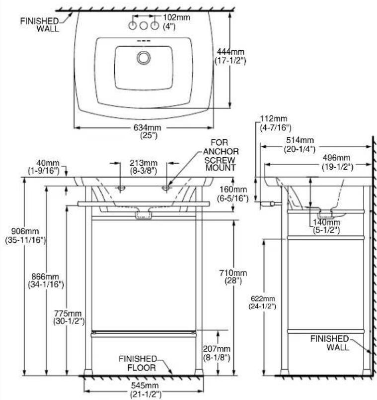
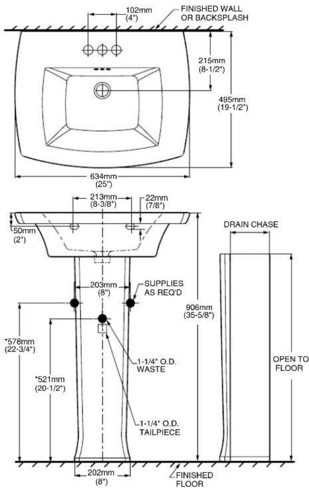
| Dimensions (W x D x H) | 775 x 634 x 906 mm (console set) |
| Sink dimensions | 495 x 634 mm (width x depth) |
| Installation type | Wall-mounted with mounting screws |
| Supply connections | Hot and cold water (standard) |
| Drain diameter | 1-1/4 in (32 mm) |
| Integrated towel bar | Yes (for console model) |
| Recommended mounting height | 906 mm from finished floor |
| Care and cleaning | Rinse with clean water, dry with a soft cloth. Avoid soaps, acids, abrasives. |
| Safety | Fragile product - handle with care |
| Warranty | Limited one-year warranty |
| Package contents | Sink, console/pedestal, assembly screws, adjustable bumpers |
| Recommended tools for installation | Level, pencil, 1/4 in drill bit, sealing putty |
| Wall mounting type | Headless support screws (5/16 in) with nuts and washers |
| Console material | Chrome-plated steel (or unspecified metal) |
| Weight | Not specified |
Frequently Asked Questions - Edgemere 0445800 American Standard
User questions about Edgemere 0445800 American Standard
0 question about this device. Answer the ones you know or ask your own.
Ask a new question about this device
Download the instructions for your Sink in PDF format for free! Find your manual Edgemere 0445800 - American Standard and take your electronic device back in hand. On this page are published all the documents necessary for the use of your device. Edgemere 0445800 by American Standard.
USER MANUAL Edgemere 0445800 American Standard
INSTALLATION INSTRUCTIONS CARE AND MAINTENANCE
Edgemere™
0445 Series Console / Pedestal
Thank you for selecting American Standard - the benchmark of fine quality for over 100 years. To ensure this product is installed properly, please read these instructions carefully before you begin. (Certain installations may require professional help.) Also be sure your installation conforms to local codes.
CAUTION: PRODUCT IS FRAGILE. TO AVOID BREAKAGE AND POSSIBLE INJURY HANDLE WITH CARE! NOTE: Pictures may not exactly define contour of china and components.
OBSERVE LOCAL PLUMBING AND BUILDING CODES
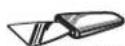
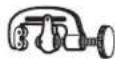
Recommended Tools & Materials
Putty Knife
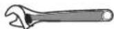
Adjustable Wrench

Hacksaw
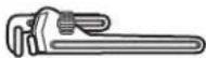
Pipe Wrench
Tubing Cutter
Basin Wrench
Level
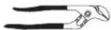
Channel Lock Pliers
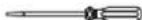
Regular Screwdriver
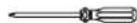
Phillips Screwdriver
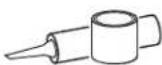
Plumbers' Putty or Caulking
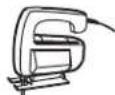
Saber Saw

Tape Measure
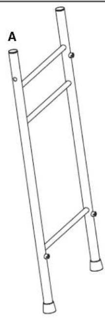
Edgemere Console Lavatory Edgemere Pedestal Lavatory
7302242-100A
natural_image
Line drawing of a ladder structure with two legs and four feet, labeled 'A' (no text or symbols on the ladder itself)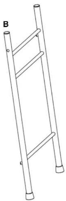
natural_image
Line drawing of a ladder structure with two legs and a handle, labeled 'B' (no text or symbols on the ladder itself)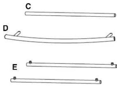
natural_image
Three horizontal line segments labeled C, D, and E, each with a small 'a' mark at the end (no text or symbols on the lines themselves)
natural_image
Simple line drawing of a parallelogram labeled F and a series of dots labeled G below (no text or symbols on the diagram itself)CONSOLE ASSEMBLY
1
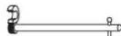
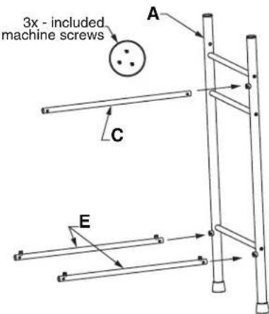
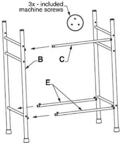
Insert the back top support tube (C) as well as both shelf support tubes (E) into the exposed tube housings in the left side leg sub-assembly (A) as shown. Align the support tubes such that the holes in the support tubes line up with the threaded housings in the side leg sub-assembly. Using 3 of the provided machine screws, tightly secure the support tubes into the side leg sub-assembly.
2
Insert the right side leg sub-assembly (B) into the exposed ends of support tubes (C, E) as shown. Make sure to align the support tubes holes to the threaded portion of the side leg sub-assembly housings. Using 3 of the provided machine screws, tightly secure the support tubes into the right side leg sub-assembly.
3
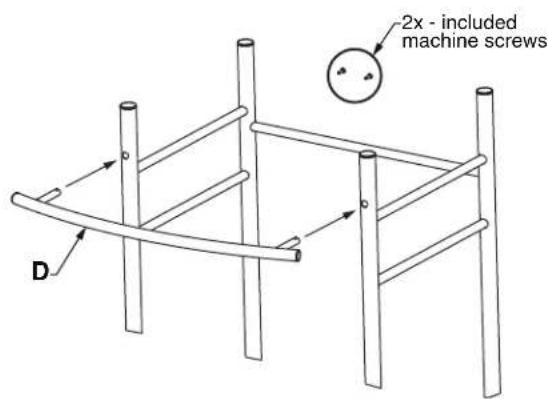
Insert the towel bar (D) into the two exposed holes on the upper front legs of the console assembly. Using the final 2 machine screws, tightly secure the towel rack to the console.
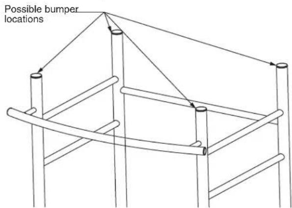
4
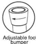
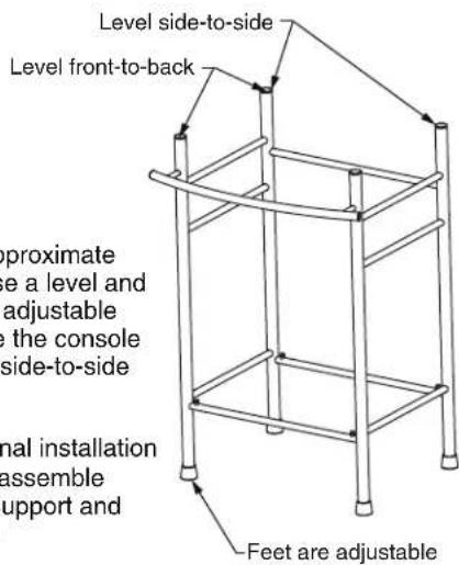
Place assembly into approximate installation position. Use a level and the four independently adjustable foot bumpers to ensure the console assembly is level both side-to-side and front-to-back.
Note: Wait until after final installation of console and sink to assemble glass shelf onto shelf support and remove protective film.
PEDESTAL AND CONSOLE LAVATORY INSTALLATION
1 Wall Preparation for Sink and Pedestal/Console Installation
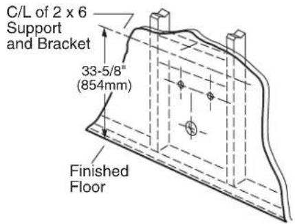
Provide suitable reinforcement behind finished wall for sink hanger screws. For an installed sink height of 35-5/8" (905mm) center the reinforcement 33-5/8" (854mm) above the floor
Note: If replacing an existing sink be certain to shut off water supply prior to removing old sink.
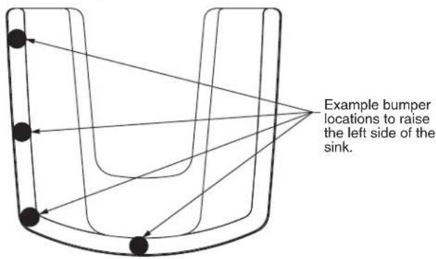
2 Preparation of Sink and Pedestal/Console
- Place pedestal/console into approximate position near wall.
- Place sink on pedestal/console, aligning recesses on the underside of the sink to the respective location on pedestal/console.
- Place a level on the sink and pedestal/console assembly.
- If necessary use one or more of the included bumper cushions to level and cushion sink slab to pedestal/console.
-
Move sink and pedestal/console assembly into contact with wall.
-
With a pencil, mark through the center of the two mounting holes found on the back of the sink. (If securing pedestal to floor, mark the center of holes on the bottom of the pedestal.)
Top of Console
Top of Pedestal
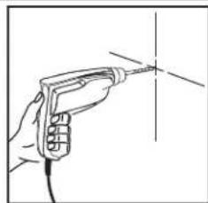
3 Anchor Screw Installation
- Move the assembly well clear of the wall.
-
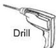
Drill two pilot holes at the center marks using a 1/4" drill bit.
-
Thread the two 5/16" headless hanger screws leaving 1-7/8" (48 mm) of the threaded end exposed as illustrated.
Note: Pedestal is not provided with mounting hardware. Various pedestal screw sizes and types are available to the installer at local hardware outlets.
natural_image
Hand holding a handheld electric drill bit with a pointed tip, no text or symbols visible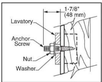
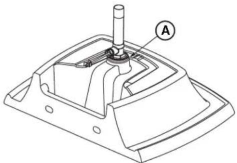
4 Faucet and Drain Installation
- Following manufacturer's instructions, install faucet and drain assembly (not included).
- Apply a bead of sealing putty on the underside of the drain (see detail A) in order to ensure a watertight seal between the sink and the drain. Remove excess putty after installing drain on sink.
- Return the sink assembly to the installed position, guiding the sink over the two headless hanger screws.
- Connect the trap to drain assembly and hand-tighten to check alignment. It may be necessary to cut off part of the tailpiece (see detail B) or part of the horizontal leg of the trap (see detail C).
natural_image
Technical line drawing of a mechanical assembly with labeled component A (no text or symbols beyond label)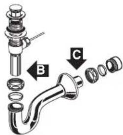
5 Sink and Pedestal/Console Installation
- Secure sink to wall, install washers and hand tighten nuts.
- Connect hot and cold supply lines between the fitting valve and the supply shut-off valves.
- Tighten trap joints for watertight assembly.
- Apply a bead of caulk around the back edge of the sink where it contacts the wall.
Note: For sink and console assembly, insert rectangular glass shelf onto the shelf support and remove protective film from glass shelf.
CONSOLE CARE INSTRUCTIONS: Rinse the product clean with clear water. Dry with a soft cotton flannel cloth.
DO NOT: Clean with soaps, acid, polish, abrasives, harsh cleaners, or a cloth with coarse surface.
AMERICAN STANDARD ONE-YEAR LIMITED WARRANTY
If inspection of this American Standard plumbing product, within one year after its initial purchase, confirms that it is defective in materials or workmanship, American Standard will repair or, at its option, exchange the product for a similar model.
This warranty does not apply to local building code compliance. Since local building codes vary considerably, the purchaser of this product should check with a local building or plumbing contractor to insure local code compliance before installation.
This warranty shall be void if the product has been moved from its initial place of installation; if it has been subjected to faulty maintenance, abuse, misuse, accident or other damage; if it was not installed in accordance with American Standard's instructions; or if it has been modified in a manner inconsistent with the product as shipped by American Standard.
American Standard's option to repair or exchange the product under this warranty does not cover any labor or other costs of removal or installation, nor shall American Standard be responsible for any other Incidental or consequential damages attributable to a product defect or to the repair or exchange of a defective product, all of which are expressly excluded from this warranty. (Some states or provinces do not allow the exclusion or limitation of implied warranties, so this exclusion may not apply to you.)
This warranty gives you specific legal rights. You may have other statutory rights that vary from state to state or from province to province, in which case this warranty does not affect such statutory rights.
For service under this warranty, it is suggested that a claim be made through the contractor or dealer from or through whom the product was purchased, or that a service request (including a description of the product model and of the defect) be sent to the following address:
In the United States:
American Standard Brands
1 Centennial Ave.
Piscataway, New Jersey 08855
Attention: Director of Customer Care
For residents of the United States, warranty information may also be obtained by calling the following toll free number: (800) 442-1902
www.americanstandard.com
In Canada:
AS Canada, ULC
5900 Avebury Rd.
Mississauga, Ontario
Canada L5R 3M3
Toll Free: (800) 387-0369
www.americanstandard.ca
In Mexico:
American Standard B&K Mexico
S. de R.L. de C.V.
Via Morelos #330
Col. Santa Clara
Ecatepec 55540 Edo. Mexico
Toll Free: 01-800-839-1200
www.americanstandard.com.mx
natural_image
Line drawing of a ladder structure with four legs and two feet, labeled 'A' (no text or symbols on the ladder itself)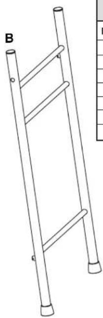
natural_image
Line drawing of a ladder structure with no text or symbolsnatural_image
Three horizontal line segments labeled C, D, and E, each with a small 'a' mark at the end (no text or symbols on the lines themselves)
natural_image
Simple line drawing of a parallelogram labeled F and a series of dots labeled G below (no text or symbols on the diagram itself)ENSAMBLAJE DE LA CONSOLA
1
natural_image
Hand holding a handheld electric drill bit with a pointed tip, no text or symbols visibleAmerican Standard Brands
1 Centennial Ave.
Piscataway, Nueva Jersey 08855
Attention: Director of Customer Care
American Standard B&K Mexico
S. de R.L. de C.V.
Vía Morelos #330
Col. Santa Clara
Ecatepec 55540 Estado de México
Número gratuito: 01-800-839-1200
www.americanstandard.com.mx
INSTRUCTIONS D'INSTALLATION NETTOYAGE ET ENTRETIEN
Edgemere™
natural_image
Line drawing of a ladder structure with two vertical posts and a horizontal bar, labeled 'A' (no text or symbols on the ladder itself)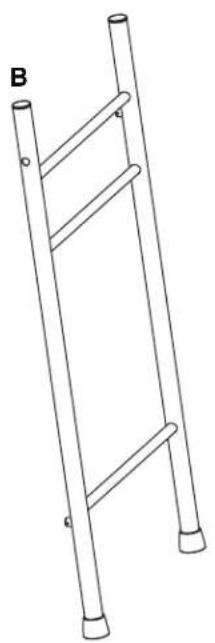
natural_image
Line drawing of a ladder structure with two legs and a side post, labeled 'B' (no text or symbols on the ladder itself)8719 LISTE DES ÉLÉMENTS DE LA CONSOLE
| NO D'ARTICLE | QTÉ DESCRIPTION | |
| A | 1 | SOUS-ASSEMBLAGE DU PIED GAUCHE |
| B | 1 | SOUS-ASSEMBLAGE DU PIED DROIT |
| C | 1 | TUBE-SUPPORT SUPÉRIEUR ARRIÈRE |
| D | 1 | PORTE-SERVIETTE |
| E | 2 | TUBE-SUPPORT DE LA TABLETTE |
| F | 1 | TABLETTE EN VERRE TREMPÉ |
| G | 8 | M4 x 0,7 VIS D'ASSEMBLAGE CRUCIFORMES |

natural_image
Four labeled diagrams (C, D, E) showing different types of elongated or curved lines with small 'a' marks at the end points (no text or symbols beyond labels)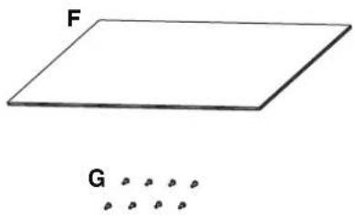
natural_image
Simple line drawing of a parallelogram labeled F and a dotted pattern below (no text or symbols on the diagram itself)ASSEMBLAGE DE LA CONSOLE
1
2
natural_image
Line drawing of a hand holding a handheld electric drill bit with a vertical axis (no text or symbols)American Standard Brands
1 Centennial Ave.
Piscataway, New Jersey 08855
American Standard B&K Mexico
S. de R.L. de C.V.
Via Morelos #330
Col. Santa Clara
Ecatepec 55540 Edo. Mexico
Sans frais : 01-800-839-1200
www.americanstandard.com.mx
- INSTALLATION INSTRUCTIONS CARE AND MAINTENANCE
- Edgemere™
- Series Console / Pedestal
- OBSERVE LOCAL PLUMBING AND BUILDING CODES
- CONSOLE ASSEMBLY
- 1
- 2
- 3
- 4
- PEDESTAL AND CONSOLE LAVATORY INSTALLATION
- Wall Preparation for Sink and Pedestal/Console Installation
- Preparation of Sink and Pedestal/Console
- Anchor Screw Installation
- Faucet and Drain Installation
- Sink and Pedestal/Console Installation
- AMERICAN STANDARD ONE-YEAR LIMITED WARRANTY
- In the United States:
- In Canada:
- In Mexico:
- ENSAMBLAJE DE LA CONSOLA
- INSTRUCTIONS D'INSTALLATION NETTOYAGE ET ENTRETIEN
- ASSEMBLAGE DE LA CONSOLE
Brand : American Standard
Model : Edgemere 0445800
Category : Sink