C5MK223 - Storage furniture Middle Atlantic - Free user manual and instructions
Find the device manual for free C5MK223 Middle Atlantic in PDF.
User questions about C5MK223 Middle Atlantic
0 question about this device. Answer the ones you know or ask your own.
Ask a new question about this device
Download the instructions for your Storage furniture in PDF format for free! Find your manual C5MK223 - Middle Atlantic and take your electronic device back in hand. On this page are published all the documents necessary for the use of your device. C5MK223 by Middle Atlantic.
USER MANUAL C5MK223 Middle Atlantic
Thank you for purchasing the C5 Series credenza rack. Please read these instructions thoroughly before installing or assembling this product.
PRODUCT FEATURES
- Built-in thermostatically controlled cooling.
- Heavy duty frame ships separate to allow for equipment integration before finished surfaces are attached.
Available in a variety of color options. - There are 14 rackspaces per bay.
Factory installed casters.
MIDDLE ATLANTIC
A brand of 1 legend
I-00661 Rev K
TABLE OF CONTENTS
Important Safety Instructions. 3-5
Weight Ratings. 5
Supplied Components and Hardware 6
Required Tools. 6
Introduction. 7
Understanding Blower Operation 8
Viewing The Blue LED Power Indicator on Blower. 8
Installing Rear Anti-Tip Feet (C5-FF2-X Models Only) 9
Lowering Front and Rear Anti-Tip Feet. 9
Installing Vent. 9
Installing Side Panels 10
Installing Top Surface 10
Installing Doors. 11
Adjusting The Door(s) 12
Installing Knob or Door Pull. 12
Installing Spring Latch. 13
Warranty. 14
IMPORTANT SAFETY INSTRUCTIONS - EN
- Read these instructions.
Heed all warnings.
Clean only with dry cloth.
-
Keep these instructions.
-
Follow all instructions.
-
Only use attachments/accessories specified by the manufacturer.

DANGER HAZARDOUS VOLTAGE: The lightning flash with the arrowhead symbol, within an equilateral triangle is intended to alert the user to the presence of uninsulated dangerous voltage within the product's enclosure that may be of sufficient magnitude to constitute a risk of electric shock to persons.

WARNING: A warning alerts you to a situation that could result in serious personal injury or death.

CAUTION: A caution alerts you to a situation that may result in minor personal injury or damage to the product and/or property.
NOTE: A note is used to highlight procedures pertaining to the installation, operation, or maintenance of the product.

WARNING: Failure to read, understand and follow the following information can result in serious personal injury, damage to the equipment or voiding of the warranty. It is the responsibility of the Installer/User to ensure that this product is loaded according to specifications.

WARNING: The weight ratings of this product can be found on the product. Exceeding these weight ratings can result in serious injury or damage to the equipment. It is the responsibility of the Installer/User to ensure the components installed do not surpass the weight ratings as an unstable condition can occur which may cause possible injury or damage.

WARNING: Death or serious injury may occur when children climb on audio and/or video equipment furniture. A remote control or toys placed on the furnishing may encourage a child to climb on the furnishing and as a result the furnishing may tip over on the child.

WARNING: Relocating audio and/or video equipment to furniture not specifically designed to support audio and/or video equipment may result in death or serious injury due to the furnishing collapsing or over turning onto a child.

WARNING: Can tip over resulting in risk of injury. Do not allow children under 16 to move cart. Move cart slowly.

Only adults should move this unit.
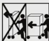
Apply moving force on narrow dimension.
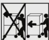
Never apply force at top, always push near middles
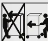
Push, do not pull.

WARNING: To reduce the risk of burns, fire, electric shock, or injury to persons:
- Close supervision is necessary when this furnishing is used by, or near children, invalids, or disabled persons.
- Use this furnishing only for its intended use as described in these instructions. Do not use attachments not recommended by the manufacturer.
- Never drop or insert any object into any opening.
- Do not use outdoors.
- For loading always put heavier items at the bottom and not near the top in order to help prevent the possibility of the furnishing tipping over.

WARNING: The apparatus shall not be exposed to dripping or splashing and that no objects filled with liquids, such as vases, shall be placed on the apparatus.

CAUTION: To avoid an unstable condition, place heavier components at the bottom of the cabinet. When more than one component is placed in the cabinet, begin at the bottom of the cabinet and place equipment at the lowest available point, evenly distribute weight (vertically) within the cabinet.

CAUTION: Watch hands and fingers around pinch points.

CAUTION: Use indoor in dry locations only.
IMPORTANT SAFETY INSTRUCTIONS - EN (CONTINUED)
When using an electrical furnishing, basic precautions should always be followed, including the following:
- For institutional use.
- Read and follow all instructions before using.
- Refer all servicing to qualified service personnel. Servicing is required when the apparatus has been damaged in any way, such as power-supply cord or plug is damaged, liquid has been spilled or objects have fallen into the apparatus, the apparatus has been exposed to rain or moisture, does not operate normally, or has been dropped.
- There are no user-serviceable components within this device. Removal of the cover from this device may present a shock hazard, and void the warranty.
INSTRUCTIONS IMPORTANTES SUR LA SECURITE - FR
Lire ces instructions.
| Model Number | Weight Rating |
| C5-FF22-X | 500 lbs. Maximum Total Rated Load With MAP Woodkit |
| C5-FF22-X | 550 lbs. Maximum Total Rated Load With User-Provided Woodkit |
NOTE: The weight rating includes a maximum of 250 lbs. on the top surface.

WARNING: This product is intended for use only with the products and maximum weights indicated. Use with other products or products heavier than the maximum weights indicated may result in instability causing possible injury. Total equipment weight must not exceed 550 lbs. (249.47 kg).

| Model Number Weight Rating | |
| C5-FF27-X 600 lbs. Maximum | Total Rated Load With MAP Woodkit |
| C5-FF31-X 600 lbs. Maximum | Total Rated Load With MAP Woodkit |
| C5-FF27-X 800 lbs. Maximum | Total Rated Load With User-Provided Woodkit |
| C5-FF31-X 800 lbs. Maximum | Total Rated Load With User-Provided Woodkit |
NOTE: The weight rating includes a maximum of 350 lbs. on the top surface.

WARNING: This product is intended for use only with the products and maximum weights indicated. Use with other products or products heavier than the maximum weights indicated may result in instability causing possible injury. Total equipment weight must not exceed 800 lbs. (362.87 kg).

If any pieces are missing or damaged, please report it immediately to Technical Support at av/support@legrand.com or (866) 977-3901.
SPRING LATCH KIT (91-00508)

4-40 x 1/4" Machine Screw A

4 x 1/2" Sheet Metal Screw B

Spring Latch C
| Configuration | Qty. |
| 1-Bay | 3 |
| 2-Bay | 6 |
| 3-Bay 9 |
| Configuration | Qty. |
| 1-Bay | 3 |
| 2-Bay | 6 |
| 3-Bay 9 |
| Configuration | Qty. |
| 1-Bay | 1 |
| 2-Bay | 2 |
| 3-Bay 3 |
TOP KIT (91-00517)

10 x 5/8" Pan Head Screw D
| Configuration | Qty. |
| 1-Bay | 12 |
| 2-Bay | 12 |
| 3-Bay 12 |
DOOR INSTALLATION KIT (91-00518)

6 x ½" Wood
Screw
E
Phillips Screw F

Clear Bumper G
| Configuration | Qty. |
| 1-Bay | 3 |
| 2-Bay | 6 |
| 3-Bay 9 |
| Configuration | Qty. |
| 1-Bay | 3 |
| 2-Bay | 6 |
| 3-Bay 9 |
| Configuration | Qty. |
| 1-Bay | 3 |
| 2-Bay | 6 |
| 3-Bay 9 |
FOR 2- AND 3-BAY C5-FF22-X MODELS ONLY

(8x)
10-32 x 38 Thread Forming Screws H
(2x) Rear Anti-Tip Feet J
PANEL KIT (91-00507)

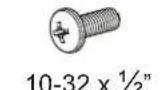
(4x) 10-32 x 1/2" Phillips Screw K
NOTE:
To order more hardware, contact support at av/support@legrand.com or (866) 977-3901.
Additional hardware is included that may not be required for your installation.
REQUIRED TOOLS
- Phillips Screwdriver
- Hammer
- 5/16" Deep Socket

WARNING: Use tools with caution and follow all necessary safety protocols.
- Please take the time to carefully unpack and inspect all components and gather all corresponding instruction sheets.
- Instruction sheets may also be accessed at www.legrandav.com.
- Maintenance and care information is provided in Care and Cleaning of Products (I-00788) and Unpacking and Handling Precautions (I-00787) for your convenience.
Color Options: The C5 Credenza is available in a variety of color options. For more information, refer to www.legrandav.com.
Review notes regarding the anti-tip feet before assembling your credenza.
FOR 2- AND 3-BAY C5-FF22-X MODELS ONLY: Install the rear anti-tip feet before proceeding. For more information, refer to "Installing Rear Anti-Tip Feet (C5-FF22-X Models Only)" on page 9.
- Rear anti-tip feet are pre-installed on 1-bay models.
- Front anti-tip feet are pre-installed on all models.
- For more information regarding how to lower the front and rear anti-tip feet, refer to "Lowering Front and Rear Anti-Tip Feet" on page 9.
C5 Series Documentation Set:
Refer to the following instruction sheets to install the C5 Series options you may have purchased for your credenza.
Rear Bay Extender Installation Instruction Sheet (I-00701)
- Shelf System Insert Instruction Sheet (I-00500)
Large Format Display Mount System Instruction Sheet (I-00749)
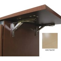
- Flip-Up Side Shelf Instruction Sheet (I-00689)
C5 Adjustable Rear Rail Brackets Instruction Sheet (I-00730)
- Rotating Sliding Rail System for C5-D Deep Credenza Rack (I-00573)
- Anti-Tip Feet Field Installation for Rotating Sliding Rail System (100-00019)
- Waste Basket Insert Instruction Sheet (I-00498)
- Replacement Blower Kit Instruction Sheet (100-00021)
Millwork Kit Drawings Instruction Sheet (I-00733)
- Review Woodworker's Kit Page on www.legrandav.com and perform the installation.
If you are providing your own woodwork for your credenza , access the Woodworker's Kit page at:
https://www.legrandav.com/c5-woodworkers-kit
- Download a .zip file of engineering drawings by clicking the C5 part number that corresponds with the width, hardware finish, and frame style of your lectern.
- When reviewing the drawings provided in the .zip file, analyze the frame measurements and dimensions for the C5 Series Woodkit (the one that we sell) when creating your own custom woodkit.
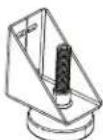
FOR 1-BAY MODEL ONLY: Only one master blower is pre-installed on top of credenza frame. (FIGURE A)
FOR 2-BAY AND 3-BAY MODELS ONLY: A master blower and remote blower(s) are pre-installed on top of credenza frame. Only the remote blower has an interconnect lead coming out of the rear (and is powered by the master).

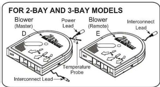
NOTE: Blowers isolated for clarity.
FIGURE A
NOTE:
- Position probe near hottest equipment.
The blower fan turns on at 87^ (30.5^) and runs proportionately.
The blower fan speed increases with temperature from 87^ (30.5^) to 95^ (35^) . - At 95^ (35^) and above, the blower fan runs at full speed.
The blower fan stops running at 85^ (29.4^)
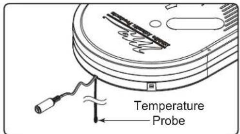
FIGURE B
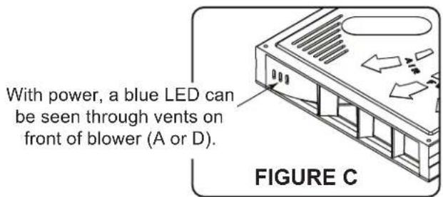
VIEWING THE BLUE LED POWER INDICATOR ON BLOWER
FOR 1-BAY MODELS: A blue LED illuminates from inside the vents on the front of the blower when the unit is receiving power. (FIGURE C)
FOR 2- AND 3-BAY MODELS: A blue LED illuminates from inside the vents on the front of the master blower when the system is receiving power.
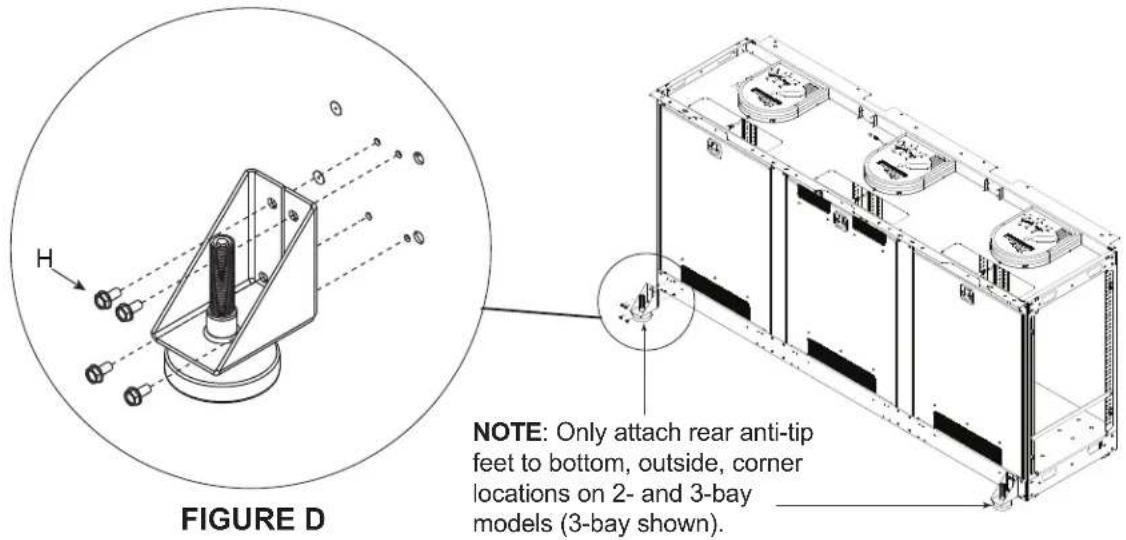
INSTALLING REAR ANTI-TIP FEET (C5-FF22-X MODELS ONLY)
FOR 1-BAY MODELS: Rear anti-tip feet are pre-installed.
FOR 2- AND 3-BAY MODELS: Install rear anti-tip feet before assembling your credenza.
- Use a 5/16" deep socket and (8x) 10 - 32 × 3% " thread forming screws (H) to install both rear anti-tip feet to the outside locations of your credenza as shown. (FIGURE D)
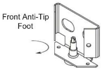
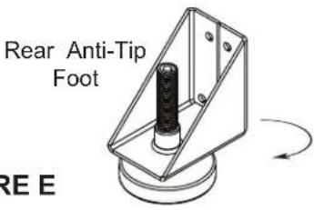
LOWERING FRONT AND REAR ANTI-TIP FEET
- Unscrew front and rear anti-tip feet (H) from brackets, as shown. (FIGURE E)
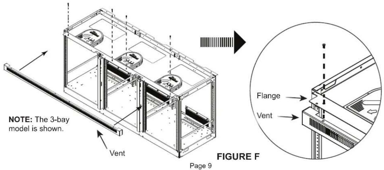
INSTALLING VENT
- Place vent underneath the flange. (FIGURE F)
- Use a #2 Phillips and 10 - 32 × 112 machine screws (K) to attach the vent into the top of the frame.
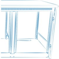
INSTALLING SIDE PANELS
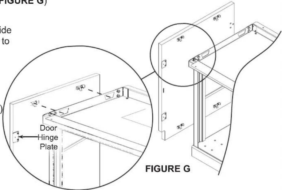
FOR C5-FF27-X and C5-FF31-X MODELS ONLY: If installing a C5MM monitor mount kit, install stabilizing feet and monitor mount support brackets prior to attaching wood-side panels and doors to frame. For more information, refer to the C5 Large Format Display Mount System Instruction Sheet (I-00749) at www.legrandav.com. (FIGURE G)
NOTE: If installing a Flip-Up Side Shelf, install prior to installing the side panels. For more information, refer to the Flip-Up Side Shelf Instruction Sheet (I-00689) at www.legrandav.com
Install side panels by placing the (4x) pre-installed hooks into (4x) slots located on each side of the credenza frame.
INSTALLING TOP SURFACE
FOR C5-FF27-X AND C5-FF31-X MODELS ONLY: For accessories related to the top surface, refer to the "Introduction" on page 7, before proceeding with the following installation.
NOTE: To help protect the wood finish from scratching, do not place any components or tools on unprotected wood surface during assembly. For wood kit care and cleaning, refer to I-00788.
- Align the top using wooden dowels (where applicable) in the side panels as a guide.
- Attach top surface to the frame using #10 x 5 / 8 wood screws (D), extra screws provided if needed. (FIGURE H)
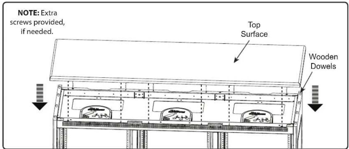
FIGURE H
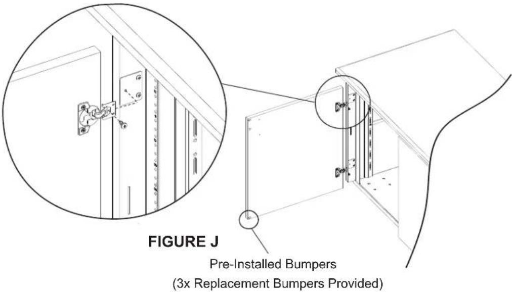
INSTALLING DOORS
FOR ALL MODELS: Follow the step listed below to install the outer doors to the wood side panels.
NOTE: If using an electric drill, verify the torque is on the lightest setting and only increase as necessary.
Use (2x) #6 x ½" wood screws (E) per side, to attach the door(s) to the wood side panel, as shown. (FIGURE J)
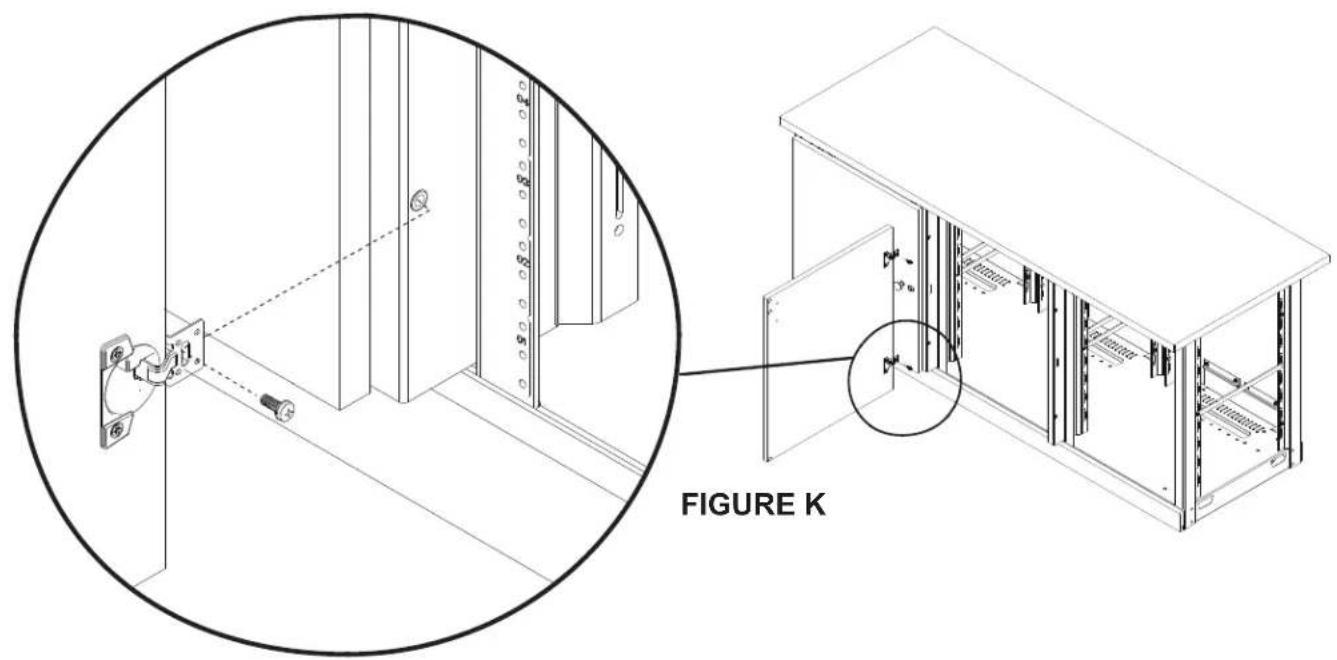
FOR 3-BAY MODELS ONLY: Follow the step listed below to install the middle and right doors to the metal frame of your credenza. Middle and right doors follow the same orientation.
NOTE: If using an electric drill, verify the torque is on the lightest setting and only increase as necessary.
- Use (2x) 10 - 32 × 1/2 machine screws (F) to attach door to the metal frame, as shown. (FIGURE K)
- If necessary, use a #2 Phillips screwdriver to adjust door hinges, as shown. (FIGURE L)
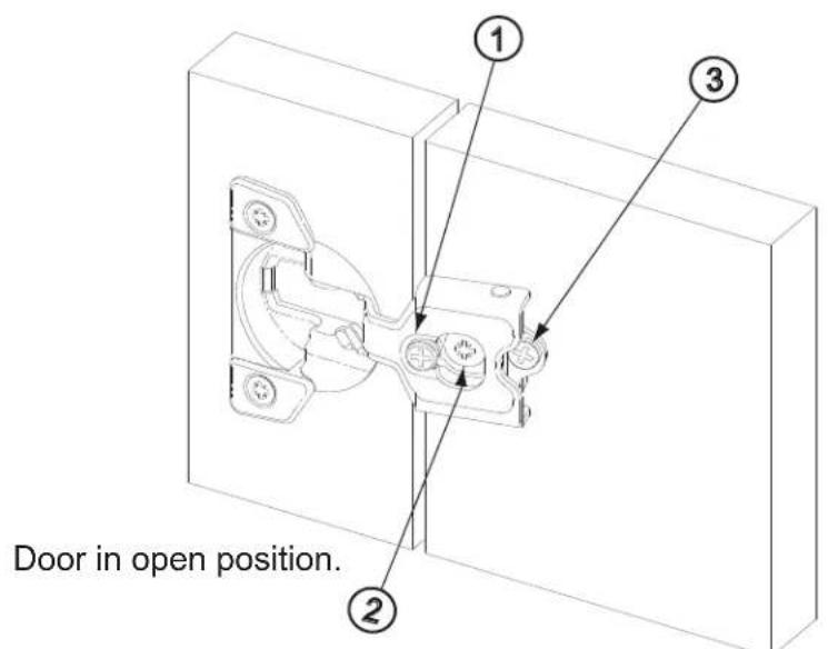
FIGURE L
① Side Adjustment: Adjusts horizontal placement of door. Adjusts door-to-door gap.
② Height Adjustment: Adjusts vertical height of door.
Depth Adjustment: Adjusts the space between the door and the face of the frame of credenza.
INSTALLING KNOB OR DOOR PULL
- Install knob or door pull into pre-drilled pilot holes, as shown. (FIGURE M)
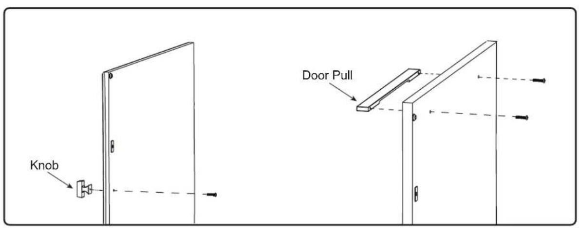
FIGURE M
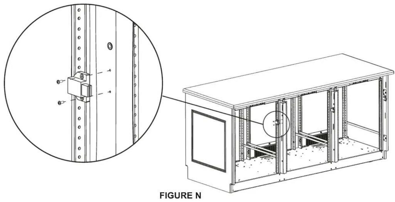
INSTALLING SPRING LATCH
Install latch using (2x) screws per spring latch (C), as shown. (FIGURE N)
FOR METAL FRAME: Use 4 - 40 × 1% machine screws (A) when installing spring latch (C) into frame.
FOR WOOD KIT: Use #4 x 12 wood screws (B) when installing spring latch (C) into wood.
For warranty information, refer to www.legrandav.com/policies/warranty_information.
Contacting Corporate Headquarters
P: (866) 977-3901 | F: (877) 894-6918 | www.legrandav.com | av/support@legrand.com
Contacting Middle Atlantic Canada
P: (888) 766-9770 | F: (888) 599-5009 | ca.middleatlantic.com | av.canadaUSTOMerservice@legrand.com
Contacting Middle Atlantic Europe, Middle East, and Africa (EMEA) Technical Support
P: +31 495-726-003 | av.emea.middleatlantic/support@legrand.com
United States (US)
Legrand | AV Headquarters
6436 City West Parkway
Eden Prairie, MN, 55344, USA
European Union (EU)
Legrand AV Netherlands
DK, Weert, Netherlands
United Kingdom (UK)
Starline Holding Technology Ltd.
(Authorized Representative)
Unit C, Island Rd.
Reading RG2, 0RP-UK
At Legrand AV Inc. we are always listening. Your comments are welcome.
Legrand AV is an ISO 9001 and ISO 14001 Registered Company.
MIDDLE ATLANTIC
A brand of legrand