HeatDuctPro 15kW - Heating Eurom - Free user manual and instructions
Find the device manual for free HeatDuctPro 15kW Eurom in PDF.



| Product type | Forced air electric supplementary heater |
| Brand | Eurom |
| Model | HeatDuctPro 15kW |
| Nominal power | 15.0 kW |
| Supply voltage | 400 V ~ 3N, 50 Hz |
| Maximum power | 15000 W |
| Power settings | 0 - 7500 - 15000 W |
| Airflow rate | 1609 m³/h |
| Protection class | IP24 |
| Dimensions (L × W × H) | 71.4 × 47.6 × 53.4 cm |
| Weight | 27.8 kg |
| Plug type | 5-pin plug 32 A |
| Cable length | 150 cm (H07RN-F5G2.5 mm²) |
| Thermostat | Mechanical, continuously adjustable |
| Overheat protection | Yes, automatic shutdown |
| Cooling system | Ventilation after shutdown for 3 to 4 minutes |
| Flexible connection | Possible (max. 5 m, adaptable) |
| Recommended use | Workshops, garages, warehouses, rooms ≥ 150 m³ |
| Cleaning | Dry cloth or vacuum cleaner on the grilles |
| Safety | Do not cover, minimum distance 1 m from flammable objects |
Frequently Asked Questions - HeatDuctPro 15kW Eurom
User questions about HeatDuctPro 15kW Eurom
0 question about this device. Answer the ones you know or ask your own.
Ask a new question about this device
Download the instructions for your Heating in PDF format for free! Find your manual HeatDuctPro 15kW - Eurom and take your electronic device back in hand. On this page are published all the documents necessary for the use of your device. HeatDuctPro 15kW by Eurom.
USER MANUAL HeatDuctPro 15kW Eurom
natural_image
Two industrial heat exchangers with visible cooling fans and ventilation ducts, one labeled 9kW (no text or symbols on the devices themselves)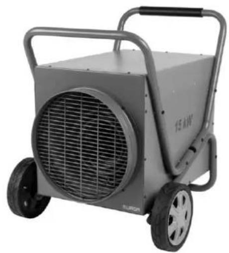
natural_image
Exterior view of a gray industrial heater with visible fan grille and wheels (no text or symbols)Heat-Duct-Pro 3 - 9 - 15 kW
Art.nr. 332469 - 332483 - 332490
This product is only suitable for well insulated spaces of occasional use.
1 = schroef M5x22
2 = Veerring ∅5
3 = plat ringetje ∅5 × 10
• Montage trolley HDP 15
natural_image
Symbol of a trash bin with crossed lines indicating no waste or discharge, and a solid black rectangle below (no text or labels)• Montage Handgriff HDP 3+9
flowchart
graph LR
    A["1: Fan with fan blade"] --> B["2: Fan with fan blade"]
    B --> C["3: Fan with fan blade"]
    C --> D["4: Fan with fan blade"]
    D --> E["5: Fan with fan blade"]
    E --> F["6: Fan with fan blade"]
natural_image
Symbol of a trash bin with crossed lines indicating no waste or discharge, and a solid black rectangle below (no text or labels)Thank you very much for choosing for a Eurom device. You have made a good choice! We hope you will be satisfied about its functioning.
To get maximum profit from your panel, it is important to read this manual attentive and totally before use, and to understand what is written. Read especially the safety instructions: they are there to protect you and your environment.
Keep the manual in a safe place for future reference. Store also the package: that is the best protection for your heater in times of no-use. And if you at any time pass the appliance on, pass on the manual and package too.
We wish you a lot of fun with the Heat-Duct-Pro!
Eurom
Kokosstraat 20
8281 JC Genemuiden (NL)
info@eurom.nl
www.eurom.nl
This manual has been complied with the utmost care. Nevertheless, we reserve the right to optimize this manual at any time and to adjust it technically. The images used may differ.
Symbol statement
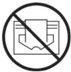
Do not cover your device!
Technical data
| Type | Heat-Duct-Pro 3 | Heat-Duct-Pro 9 | Heat-Duct-Pro 15 | |
| Supply voltage | V / Hz | 220-240~50 | 400-3N~50 | 400-3N~50 |
| Maximum capacity | W | 3000 | 9000 | 15000 |
| Settings | W | 0-3000 | 0-4500-9000 | 0-7500-15000 |
| Air flow | m^3/h | 389 | 1227 | 1609 |
| Protection class | IP24 | IP24 | IP24 | |
| Electrical cable | H07RN-F3G1,5mm ^2 150cm | H07RN-F5G1,5mm ^2 150cm | H07RN-F5G2,5mm ^2 150cm | |
| Plug | Schuko | 5 pole - 16A | 5 pole - 32A | |
| Dimensions | cm | 36,5x26,5x37 | 46x31,5x42 | 71,4x47,6x53,4 |
| Weight | kg | 6,0 | 11,7 | 27,8 |
General safety instructions
- Before using the machine, carefully read this entire instruction manual. Keep this booklet in a safe place for reference.
- Before using your new heater, check it, including cord and plug, for any visible damage. Do not use a damaged heater, but send it back to your dealer for replacement.
- This heater is exclusively intended to heat workspaces such as workshops, garages and storage spaces. Use the appliance for this purpose only.
- Under the terms and conditions described in this leaflet, the heater can be used in wet or damp indoor spaces such as bathrooms and laundry rooms. Do not place the heater in the vicinity (at least 1 meter removes) of taps, bathtub, shower, pool, fountains or other sources of moisture. Make sure it cannot fall into water and prevent water from getting into the heater itself. If, at any time, the heater does fall into water, unplug it immediately! Do not use a heater that has a damp interior but have it repaired. Never immerse the heater, cord or plug in water and never touch it with wet hands.
-
The supply voltage and utility frequency, specified on the machine, need to match those of the socket that is used. The electrical installation needs to be protected by a residual current device (max. 30 mAmp).
-
Fully extend the cord before plugging in the heater. Make sure it does not come into contact with any part of the heater and prevent it from heating up any other way. Do not run the cord underneath carpeting; do not cover it with mats, carpet strips, or similar and make sure it is not placed in any passageways. Make sure the cord cannot be stepped on and that no furniture is placed on top of it. Do not lead the cord around sharp corners and do not roll it up too tightly after use! Do not rotate or kink the cable and do not wind it around the stove as this can damage the insulation! Be careful! Some parts of this product can become very hot and cause burns. Particular attention has to be given where children and vulnerable people are present. do not let bare skin come into contact with hot surfaces. Check the electrical cable and the plug regularly for damage and do not use the device if you detect damage. First have it repaired.
-
If possible, do not use an extension cord, as this poses the risk of overheating and fire. If the use of an extension cord is unavoidable, then make sure it is an undamaged, approved extension cord with a minimum diameter of 2.5 mm ^2 , suitable for a minimum permissible power of 3500 Watt (HDP3) / 10.000 Watt (HDP9) / 16.000 Watt (HDP15). To prevent overheating, always fully extend the cord!
-
To prevent the circuit overloading and fuses being blown, make sure no other appliances are connected to the same socket or wired to the same electrical circuit as the heater.
-
Do not use the heater outdoors and do not use it in spaces smaller than 30m^3 (HDP3) / 90 m^3 (HDP9) / 150 m^3 (HDP 15).
-
A heater contains hot and/or glowing and sparking components. Do not, therefore, use in areas where fuels, paint, flammable liquids and/or gasses etc. are stored.
-
Do not place the heater near, under or directly opposite a socket and do not place it near an open fire or other heat source.
-
Do not use the heater near or directly opposite furniture, animals, curtains, paper, clothes, bedding or other inflammable objects. Keep them at least 1 metre away from the heater!
-
Never cover a heater! The heater's air inlets and outlets should never be obstructed in any way, so as to prevent the possibility of fire. Never use the heater to dry clothes and do not place anything on top of the heater. Do not place it on soft surfaces such as beds or deep-pile carpets, as they can block openings.
-
Make sure that the air around the heater can circulate freely. Do not place the heater too close to walls or large objects and do not place it under shelves, cupboards, and similar.
- Prevent foreign objects from entering the heater via the venting or exhaust openings as this may lead to electric shock, fire or damage.
- Never leave the heater unattended when switched on. Always switch if off before removing the plug from the socket. Always unplug the heater when not in use! Pull on the plug to remove from the socket, never pull on the cord.
-
Always switch the heater off, unplug it and leave to cool down before:
-
cleaning the heater
- carrying out maintenance to the heater
-
touching or moving the heater. Use the handle or trolley (HDP 15) for this!
-
This machine gets hot when it is in use. To prevent burns, do not let bare skin come into contact with hot surfaces.
- Do not use a timer or a similar product to automatically switch on the heater. Always perform safety checks before using the heater!
- Close supervision is necessary if the product is used near children or incapacitated persons. This appliance is not suitable to be operated by children or persons who have physical, sensory and/or mental limitations, or by persons who have no knowledge of, or experience with, this appliance. This appliance can be used by children aged from 8 years and above and persons with reduced physical, sensory or mental capabilities or lack of experience and knowledge if they have been given supervision or instruction concerning use of the appliance in a safe way and understand the hazards involved. Children shall not play with the appliance. Cleaning and user maintenance shall not be made by children without supervision.
- Keep the heater clean. Dust, dirt and/or a build up of deposits in the heater are a common cause of overheating. Make sure these deposits are removed regularly.
-
Do not turn on the appliance if you have discovered damage to the appliance, cord or plug, if the appliance is malfunctioning, if it has been dropped or if there are signs of any other defect. Return the complete product to the vendor or to a certified electrician for inspection and/or repair. Always ask for original parts.
-
Do not use attachments and/or accessories that have not been recommended or supplied by the manufacturer.
- The appliance (incl. cord and plug) may only be opened and/or repaired by properly authorised and qualified persons.
- Only use this heater for its intended purpose and as described in this instruction manual.
Not abiding by instructions 23, 24 and 25 may lead to damage, fire and/or personal injuries. A failure to adhere to these rules also immediately nullifies the guarantee and vendor, importer and/or manufacturer do not take responsibility for any of the consequences!
Description
EUROM Heat-Duct-Pro heaters are 'real space' heaters, with a powerful fan which disseminates a great deal of air.
Cold air is sucked in at the back, heated, and then blown out as hot air. Because a relatively large quantity of air is sucked in and blown out, the air expelled by the heater does not feel particularly hot. As a great deal of air is heated and blown out, however, the entire space (not just the air around the heater!) is gradually warmed up.
A hose can be connected to the discharge vent of the Heat-Duct-Pro heaters (max.
5 m) to lead the vented hot air elsewhere. For this reason the heaters have an extra powerful fan with a large air displacement.
The heater is fitted with a thermostat and overheating protection.
Heat-duct-pro 3 + 9
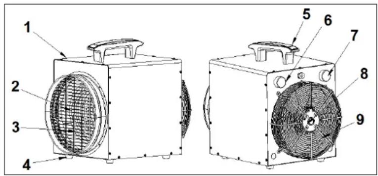
- Housing
- Air vent
- Heating coil
- Foot
-
Air inlet
-
Grip
- Thermostat knob
- Control knob
- Motor
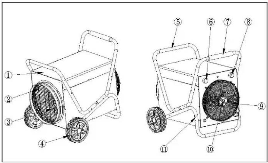
Heat-Duct-Pro 15
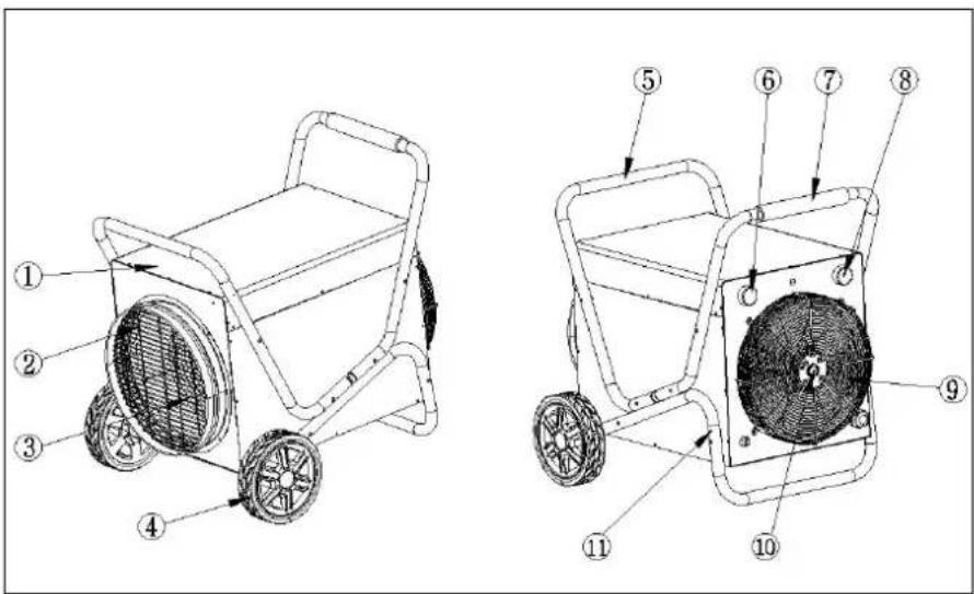
- Housing
- Air vent
- Heating coil
- Wheels
- Trolley front side
-
Thermostat knob
-
Grip
- Control knob
- Motor
- Air inlet
- Trolley rear side
Control panel
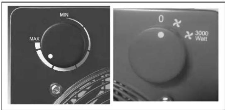
Control panel for Heat-Duct-Pro 3
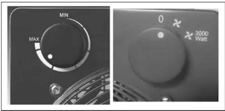
The control panel for the Heat-Duct-Pro 3 has two buttons:
- On the left the freely adjustable thermostat knob
- On the right the control knob with three settings:
0 = off
X = ventilate only
X 3000 = ventilate and heat (3000W)
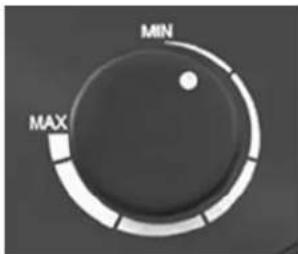
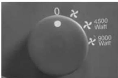
Control panel for Heat-Duct-Pro 9 and 15
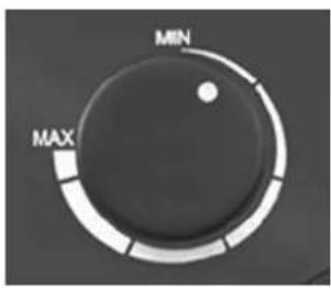
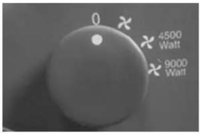
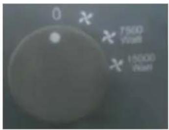
The control panel for the Heat-Duct-Pro 9 + 15 has two buttons:
• Left the freely adjustable thermostat knob
- On the right the control knob with four settings
| 0 | Off |
| × | Ventilate only |
| × 4500 watt/7500 watt | Ventilate and heat4500W (HDP 9) 7500W (HDP 15) |
| × 9000 watt/15000 watt | Ventilate and heat9000W (HDP 9) 15000W (HDP 15) |
Location and Connection
- Remove all packaging material and keep out of reach of children. After removing packaging, check the appliance for damage or other signs that could indicate a
fault/defect/malfunction. In case of doubt, do not use the appliance, but contact your vendor for inspection or replacement.
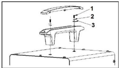
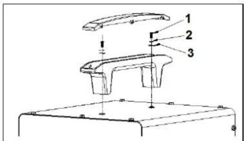
- Mounting griff HDP 3 + 9
Mount the grip as shown in the illustration.
1 = screw M5x22
2 = spring washer ∅5
3 = washer ∅5 × 10
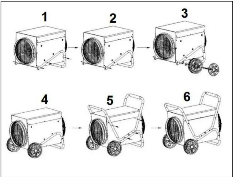
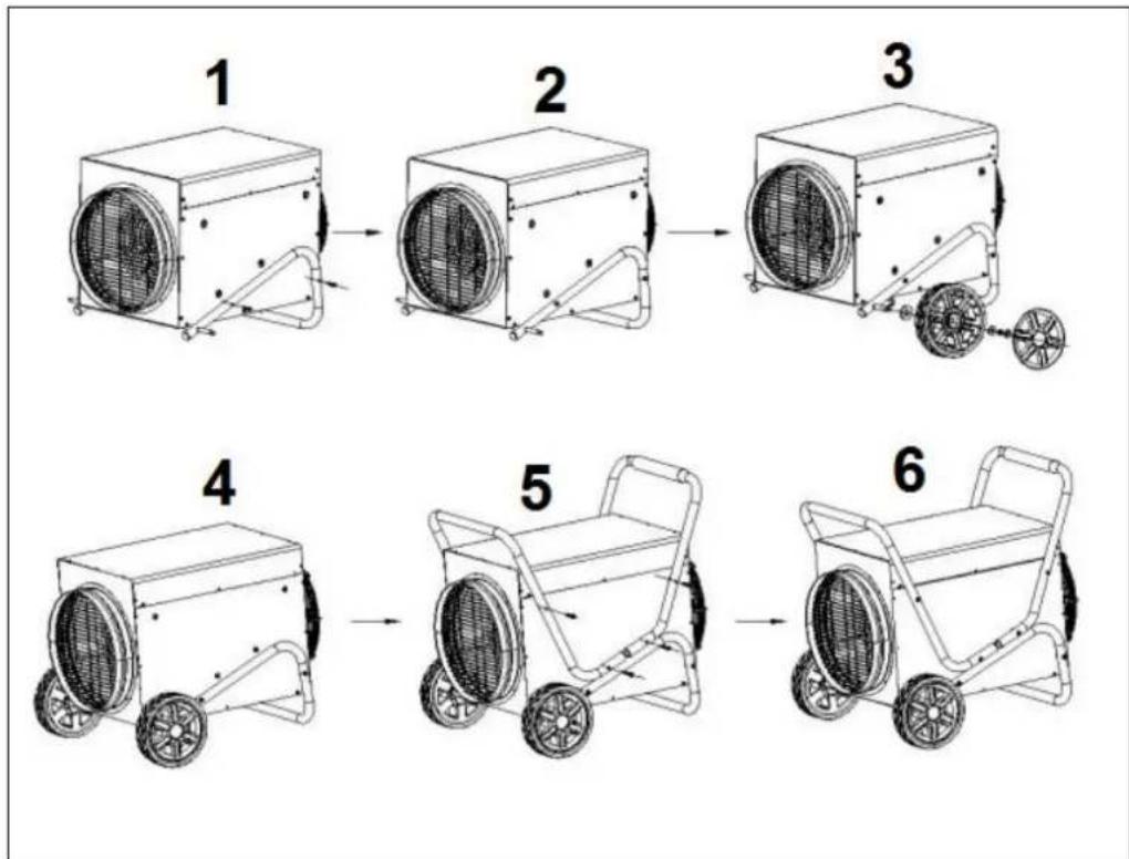
- Mounting trolley HDP 15
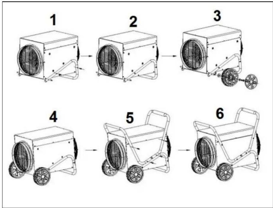
2x frame
12x screw M6x45
2x small wheels
2x plastic cover plate
4x washer
2x nut
flowchart
graph TD
    A["1: Fan 1"] --> B["2: Fan 2"]
    B --> C["3: Fan 3"]
    C --> D["4: Fan 4"]
    D --> E["5: Fan 5"]
    E --> F["6: Fan 6"]
Mount the trolley as shown in the illustration and description.
- First mount the bottom frame (see Figure 1)
- Then mount the weels (see Figure 3)
- Then mount the upper frame (see Figure 5)
- Choose a suitable location for the heater, i.e. at least one metre away from any obstructions, walls or inflammable materials (see also safety instructions).
Always ensure that the heater has sufficient space at the back to suck in air and at the front, to blow out hot air.
- Make sure the heater is always in an upright position on a solid, flat, horizontal and non-flammable surface.
- Make sure the heater is switched off (switch to O position), then plug into a correctly functioning, properly grounded 230V-50Hz (Heat-Duct-Pro 3) / 400V-50Hz, 5-Pole (Heat-Duct-Pro 9 + 15) socket.
Set-up and Operation
If the heater is being used for the first time (or if you want to reset the desired temperature), turn the thermostat dial to the maximum position (clockwise as far as it goes).
With the mode selector dial, adjust the heater to suit your preferences: fan only, half power (only Heat-Duct-Pro 9 + 15) or high power.
Once the temperature in the area being heated has reached the right level, slowly turn the thermostat dial anticlockwise until you hear a soft click; leave the dial in that position. The heater will automatically maintain the temperature at this level.
It does this by switching the heating elements off and on when the temperature rises or falls too much.
Note! After the thermostat has switched the heating elements off, the fan will keep turning. This means that the air is constantly moved, allowing the heater to accurately detect if the area is cooling down.
The thermostat dial is continuously adjustable. A higher temperature is set by turning it clockwise; a lower temperature by turning it anticlockwise.
Warning: When using for the first time, you might smell smoke. This is normal and will disappear after a short while. It occurs because some residual oil is left behind after the manufacturing process and gets heated up.
Aftercooling
The heater is supplied with an aftercooling system. When switching the heater off, turn the control knob to "off". O. The heater will first ventilate in order to cool down internally. This can take three or four minutes, depending on the ambient temperature. Then the heater will switch itself off. Make sure that you then remove the plug from the socket. With a very high ambient temperature, the heater will keep on aftercooling. In this case you can only switch it off by removing the plug from the socket.
Heat discharge hose
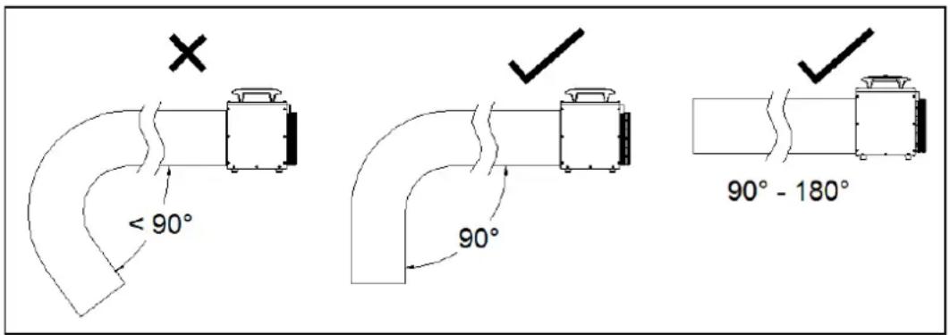
A heat discharge hose can be connected to the air vent in order to lead the heat to another space. To do this, use the special Heat-Duct-Hose: this has the right degree of heat-resistance and is supplied with a matching clamp. Also for the hose: ensure that it does not get too near to flammable materials!
Heat-Duct-Pro 3: 5 m x 26 cm, Art.no. 332414
Heat-Duct-Pro 9: 5 m x 29 cm, Art.no. 332421
Heat-Duct-Pro 15: Upon request
Before use, check that the hose and clamp are fitted properly around the vent and make sure that the hose never makes a bender smaller than 90^ .
Safety features
In case of internal overheating, the overheating safeguard will switch the heater off. This may occur if the heater cannot give off enough heat or if it cannot draw in enough fresh air. As mentioned above, this is generally caused by (partially) covering the heater, obstructing the air intake and/or outlet grills or installing the heater too close to a wall or something similar. When the heater has cooled down sufficiently, it will in principle start again automatically, however if you do not
remove the cause of the cut-off then this will probably be repeated. Regular overheating can give rise to irreparable damage. When the overheating safeguard switches the heater off, set the mode selector dial to 'OFF' (off), unplug and allow the heater to cool down. Remove and/or amend the cause of overheating and reuse the heater as normal. If you cannot find a cause and overheating recurs, stop using the heater, and take it in for inspection/repair.
Cleaning and maintenance
Keep the heater clean. Deposits of dust and dirt in the appliance are a common cause of overheating so these should be removed regularly. Switch off the heater, remove the plug from the socket and allow the heater to cool down before cleaning or carrying out maintenance work.
- Wipe the outside of the heater regularly with a dry or slightly damp cloth. Do not use aggressive soaps, sprays, cleaners or abrasives, waxes, polishes or chemical solutions and prevent water from getting into the heater itself!
- Use a vacuum cleaner or compressor to carefully remove any dust and dirt from the grills and ensure that the air intake and outlet openings are clean. Be careful not to touch or damage any internal parts during cleaning!
- The heater contains no other parts which need maintenance.
- At the end of the season, store the cleaned heater in the original packaging if possible. Store upright in a cool, dry and dust-free place.
- Do not dispose of the heater with household waste when it becomes worn or damaged beyond repair. Take it to your local authority's collection point for electrical appliances where any reusable materials will be collected and redistributed.
Removal
natural_image
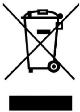
Symbol of a trash bin with crossed lines indicating no waste, above and below a solid black rectangle (no text or labels)In the EU this symbol indicates that this product may not be disposed of as ordinary household waste. Old equipment contains valuable materials, suitable for recycling. These materials should be made suitable for reuse in order to prevent any adverse effects to health and the environment caused by unregulated waste collection. Therefore, please make sure that you bring old equipment to a designated collection point. Alternatively, contact the original supplier, who can make sure that as many of the components as possible can be recycled.
CE-statement
See page 102.
Merci
natural_image
Symbol of a document with a diagonal line crossing over it, commonly used to indicate no text or symbols in the document.• Assemblage trolley HDP 15
flowchart
graph LR
    A["1: Fan with fan blade"] --> B["2: Fan with fan blade"]
    B --> C["3: Fan with fan blade"]
    C --> D["4: Fan with fan blade"]
    D --> E["5: Fan with fan blade"]
    E --> F["6: Fan with fan blade"]
natural_image
Symbol of a trash bin crossed with no text or numbers, representing waste sorting or disposal (no text present)A hose can be connected to the discharge vent of the Heat-Duct-Pro heaters (max.
- Hölje
- Luftventil
- Uppvärmningscylinder
- Underrede
-
Handtag
-
Termostatknapp
- Kontrollknapp
- Motor
- Luftintag
Heat-Duct-Pro 15
- Hölje
- Luftventil
- Uppvärmningscylinder
- Hjul
- Vagn framsida
-
Termostatknapp
-
Handtag
- Kontrollknap
- Motor
- Luftintag
- Vagn undersida
Kontrollpanel
X = endast ventilation
flowchart
graph TD
    A["1: Fan 1"] --> B["2: Fan 2"]
    B --> C["3: Fan 3"]
    C --> D["4: Fan 4"]
    D --> E["5: Fan 5"]
    E --> F["6: Fan 6"]
natural_image
Symbol of a trash bin crossed with no visible text or labels- Popis instalace vozík HDP15
natural_image
Symbol of a trash bin crossed with no text or numbers, representing waste sorting or disposal (no text present)Nezakrývajte svoje zariadenie!
Technické údaje
| Typ | Heat-Duct-Pro 3 | Heat-Duct-Pro 9 | Heat-Duct-Pro 15 | |
| Napájanie | V / Hz | 220-240~50 | 400-3N~50 | 400-3N~50 |
| Max.vermogen | W | 3000 | 9000 | 15000 |
| Nastavenia | W | 0 - 3000 | 0 - 4500 - 9000 | 0-7500-15000 |
| Vzduchovýprúd | m^3/h | 389 | 1227 | 1609 |
| Triedaochrany | IP24 | IP24 | IP24 | |
| Elektrickýkábel | H07RN-F3G1,5mm ^2 150cm | H07RN-F5G1,5mm ^2 150cm | H07RN-F5G2,5mm ^2 150cm | |
| Zásuvka | Schuko | 5-pólová - 16A | 5 pólová - 32A | |
| Rozmery | cm | 36,5 x 26,5 x 37 | 46 x 31,5 x 42 | 71,4 x 47,6 x 53,4 |
| Hmotnosť | kg | 6,0 | 11,7 | 27,8 |
- Kryt
- Vývod vzduchu
- Ohrevná špirála
- Kolesá
- Vozík predná strana
-
Spínač termostatu
-
Úchytka
- Spínač ovládača
- Motor
- Prívod vzduchu
11.Vozík spodná strana
Obslužný panel
Obslužný panel ohrievača Heat-Duct-Pro 3
Obslužný panel ohrievača Heat-Duct-Pro 3 má dva spínače:
• Vl'avo plynulo nastavitelný spínač termostatu
• Vpravo obslužný spínač s 3 pozíciami:
O = vypnuté
X = iba vetranie
X 3000 = vetranie a ohrievanie (3000W)
Obslužný panel ohrievača Heat-Duct-Pro 9+15
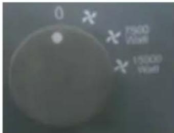
Obslužný panel ohrievača HEAT-DUCT-PRO 9+15 má dva spínače:
Montážny vozík (HDP15)
2x Kostra
12x Skrutka (M6x45
2x Kolieska
2x Plastový kryt
4x Kruh
2x Matica
flowchart
graph TD
    A["1: Fan 1"] --> B["2: Fan 2"]
    B --> C["3: Fan 3"]
    C --> D["4: Fan 4"]
    D --> E["5: Fan 5"]
    E --> F["6: Fan 6"]
natural_image
Symbol of a trash bin crossed with no text or numbers, representing waste sorting or disposal (no text present)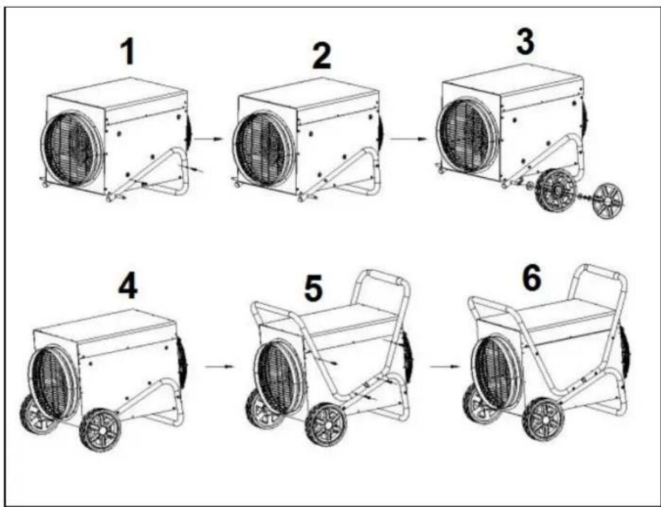
flowchart
graph TD
    A["1: Fan with fan"] --> B["2: Fan with fan"]
    B --> C["3: Fan with fan"]
    C --> D["4: Wheel cart with wheels"]
    D --> E["5: Wheel cart with wheels"]
    E --> F["6: Wheel cart with wheels"]
natural_image
Symbol of a trash bin with no text or numbers presentdeclares the following device in sole responsibility:
Product: workspace heater
Brand name: EUROM
Model: Heat-Duct-Pro 3kW / Heat-Duct-Pro 9kW / Heat-Duct-Pro 15kW
Item number: 332469 / 332483 / 332490
Complies with the following harmonization rules:
Low Voltage Directive: LVD 2014/35/EU
Electromagnetic compatibility Directive: EMC 2014/30/EU
Restriction of Hazardous Substances RoHS Directive: 2011/65/EU&(EU)2015/863
Framework Directive Ecodesign requirements: ERP 2009/125/EC
Regulation Ecodesign requirements for
Individual room heaters: (EU) 2015/1188
Regulation Ecodesign requirements Electricity
Consumption in standby and off state: 1275/2008/EC
Applied harmonized standards:
Heat-Duct-Pro 3kW
EN 60335-2-30:2009+A11:2012
EN 60335-1:2012+AC:2014+A11:2014+A13:2017+A1:2019+A14:2019+A2:2019
EN 62233:2008
EN 55014-1:2006/+A1:2009/+A2:2011
EN 55014-2:2015
EN 61000-3-2:2014
EN 61000-3-3:2013
Heat-Duct-Pro 9kW and 15kW
EN 60335-2-30:2009+A11:2012
EN 60335-1:2012+AC:2014+A11:2014+A13:2017
EN 62233:2008
EN 55014-1:2017
EN 55014-2:2015
EN 61000-3-2:2014
EN 61000-3-3:2013
EN 61000-3-11:2000
EN 61000-3-12:2011
Genemuiden, 28-04-2020
W.J. Bakker, alg. Dir.
EUROM
Kokosstraat 20
8281 JC Genemuiden
info@eurom.nl
www.eurom.nl
280420

- Heat-Duct-Pro 3 - 9 - 15 kW
- Symbol statement
- Technical data
- General safety instructions
- Description
- Heat-duct-pro 3 + 9
- Heat-Duct-Pro 15
- Control panel
- Control panel for Heat-Duct-Pro 3
- Control panel for Heat-Duct-Pro 9 and 15
- Location and Connection
- Set-up and Operation
- Aftercooling
- Heat discharge hose
- Safety features
- Cleaning and maintenance
- Removal
- CE-statement
- Merci
- Kontrollpanel
- Technické údaje
- Obslužný panel
- Obslužný panel ohrievača Heat-Duct-Pro 3
- Obslužný panel ohrievača Heat-Duct-Pro 9+15
- Montážny vozík (HDP15)
- EUROM
Brand : Eurom
Model : HeatDuctPro 15kW
Category : Heating