USER MANUAL GRWGR24 Hestan
READ THESE INSTRUCTIONS CAREFULLY AND COMPLETELY BEFORE INSTALLING OR USING YOUR APPLIANCE TO REDUCE THE RISK OF FIRE, SHOCK HAZARD, OR OTHER INJURY. KEEP THIS MANUAL FOR FUTURE REFERENCE.
Read and understand all information in this manual before attempting the installation. All plumbing and electrical work must be performed by a qualified technician and conform to all applicable state and local codes.
SAFETYDEFINITIONS
ADANGER
THIS INDICATES A HAZARD THAT WILL RESULT IN SERIOUS INJURY OR DEATH IF PRECAUTIONS ARE NOT FOLLOWED.
WARNING
THIS INDICATES A HAZARD THAT MAY RESULT IN SERIOUS INJURY OR DEATH IF PRECAUTIONS ARE NOT FOLLOWED.
CAUTION
THIS INDICATES A HAZARD WHERE MINOR INJURY OR PRODUCT OR PROPERTY DAMAGE MAY OCCUR IF PRECAUTIONS ARE NOT FOLLOWED.
INSTALLER: LEAVE THIS MANUAL WITH THE OWNER OF THE APPLIANCE.
HOMEOWNER: RETAIN THIS MANUAL FOR FUTURE REFERENCE.
MODEL NUMBERS
| Model No. Description |
| CRS_24 INDOOR / OUTDOOR REFRIGERATOR, SOLID DOOR, 24" |
| CRS_24-XX INDOOR / OUTDOOR REFRIGERATOR, SOLID DOOR, COLOR, 24" |
| GRG_24 INDOOR / OUTDOOR REFRIGERATOR, GLASS DOOR, 24" |
| GRG_24-XX INDOOR / OUTDOOR REFRIGERATOR, GLASS DOOR, COLOR, 24" |
| GRR24 INDOOR / OUTDOOR REFRIGERATOR DRAWERS, 24" |
| GRR24-XX INDOOR / OUTDOOR REFRIGERATOR DRAWERS, COLOR, 24" |
| GRFR24 INDOOR / OUTDOOR REFRIGERATOR DRAWER AND FREEZER DRAWER, 24" |
| GRFR24-XX INDOOR / OUTDOOR REFRIGERATOR DRAWER AND FREEZER DRAWER, COLOR, 24" |
| GRWS_24 INDOOR / OUTDOOR DUAL ZONE REFRIGERATOR WITH WINE, SOLID DOOR, 24" |
| GRWS_24-XX INDOOR / OUTDOOR DUAL ZONE REFRIGERATOR WITH WINE, SOLID DOOR, COLOR, 24" |
| GRWG_24 INDOOR / OUTDOOR DUAL ZONE REFRIGERATOR WITH WINE, GLASS DOOR, 24" |
| GRWG_24-XX INDOOR / OUTDOOR DUAL ZONE REFRIGERATOR WITH WINE, GLASS DOOR, COLOR, 24" |
EN
= Right() or Left (L) Hinged Model
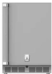
GRSR24 shown
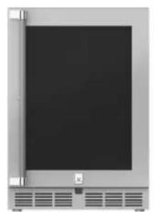
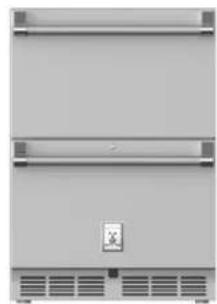
GRR24 shownGRWGR24 shown
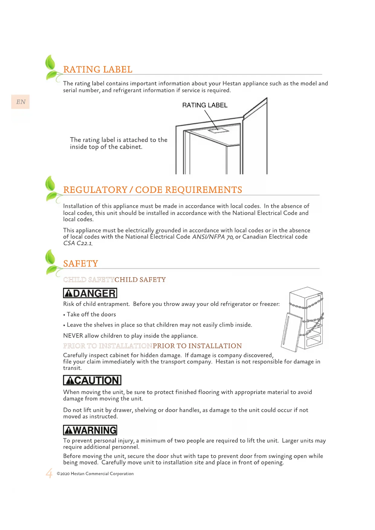
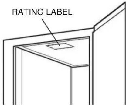
RATING LABEL
The rating label contains important information about your Hestan appliance such as the model and serial number, and refrigerant information if service is required.
The rating label is attached to the inside top of the cabinet.
REGULATORY / CODE REQUIREMENTS
Installation of this appliance must be made in accordance with local codes. In the absence of local codes, this unit should be installed in accordance with the National Electrical Code and local codes.
This appliance must be electrically grounded in accordance with local codes or in the absence of local codes with the National Electrical Code ANSI/NFPA 70, or Canadian Electrical code CSA C22.1.
SAFETY
CHILD SAFETY CHILD SAFETY
ADANGER
Risk of child entrapment. Before you throw away your old refrigerator or freezer:
Take off the doors
- Leave the shelves in place so that children may not easily climb inside.
NEVER allow children to play inside the appliance.
PRIOR TO INSTALLATION PRIOR TO INSTALLATION
Carefully inspect cabinet for hidden damage. If damage is company discovered, file your claim immediately with the transport company. Hestan is not responsible for damage in transit.
CAUTION
When moving the unit, be sure to protect finished flooring with appropriate material to avoid damage from moving the unit.
Do not lift unit by drawer, shelving or door handles, as damage to the unit could occur if not moved as instructed.
WARNING
To prevent personal injury, a minimum of two people are required to lift the unit. Larger units may require additional personnel.
Before moving the unit, secure the door shut with tape to prevent door from swinging open while being moved. Carefully move unit to installation site and place in front of opening.
CAUTION
If unit has been laid on its back or sides, place unit upright and allow a minimum of 24 hours before connecting power.
PLUMBINGPLUMBING
No plumbing connections are required. Condensate from the cooling coil is automatically evaporated through a condensate pan located in the condensing section of the unit.
DANGER
ELECTRICAL SHOCK HAZARDELECTRICAL SHOCK HAZARD
Disconnect power before installing or servicing appliance. Failure to do so can result in death or electrical shock.
ELECTRICAL GROUNDING ELECTRICAL GROUNDING
- This appliance must be grounded. Grounding reduces the risk of electric shock in the event of a short circuit.
DO NOT ground to a gas pipe.
DO NOT use an extension cord with this appliance.
- DO NOT have a fuse in the NEUTRAL or GROUNDING circuit. A fuse in the NEUTRAL or GROUNDING circuit could result in an electrical shock.

ELECTRICAL SUPPLY ELECTRICAL SUPPLY
A 115 volt AC, 60 Hz, 15 Amp circuit breaker and electrical supply is required. A Ground Fault Circuit Interrupter (GFCI) protected circuit must be used when installed outdoors.
This appliance is NOT designed for installation in manufactured (mobile) homes or recreational park trailers.
All units are provided with a 5 ft [1.5 m] cord with three-prong grounding plug. It is imperative that this plug be connected to a properly grounded three-prong receptacle. If the receptacle is not the proper grounding type, contact an electrician. The receptacle must be flush or recessed into the wall surface behind the unit.
- Never remove the grounding prong from this plug.
- Never use a 2-prong adapter.
- Never use an extension cord to connect power to the unit.
- If a 2-prong receptacle is encountered, or a longer power cord is required, contract a qualified electrician to have it replaced in accordance with applicable electrical codes.
CAUTION
Do not attempt to operate the equipment on any other power source than that listed on the Electrical Specification Plate attached to the unit.
All electrical instructions assume the outlet is located 4 - 10^ [10 - 25 cm] above the floor surface.
Floor must be level in area of installation. Leg levelers are used for fine-tune adjustment only and should not be used to compensate for floor differences exceeding 1/2'' [13 mm].
ANTI-TIP BRACKETSANTI-TIP BRACKETS
Unit may tip forward if loaded racks/shelves are all pulled out at the same time. To prevent tipping, and to provide stable installation, the unit must be secured in place with the anti-tip brackets supplied with the unit. The anti-tip brackets, when properly installed, should secure the rear legs/glides to the mounting surface and prevent the unit from tipping forward.
NOTE: Anti-tip brackets are only used for stationary cabinets and should not be installed on cabinets with accessory casters. Caster kits are available for Hestan models. Refer to the instructions supplied with the caster kit for proper installation.
Note: If installing on a concrete floor, concrete fasteners are required and not included with the anti-tip kit.
Note: Some installation sites may require modifications to provide a secure surface for attaching the brackets.
A set of anti-tip brackets is supplied with the unit. These brackets should be attached to the floor at the rear of the unit. Each bracket must be located to engage the rear legs when the cabinet is pushed back into position. Refer to Figure 1 (shown below) for anti-tip bracket mounting locations.
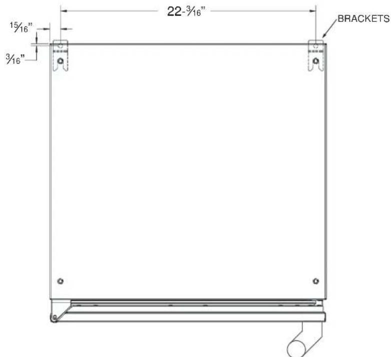
Figure 1. 24" Anti-Tip Kit
PREPARING THE SPACE PREPARING THE SPACE
CAUTION
If the unit is to be installed under a countertop, it is recommended that the countertop be supported by a structure other than the unit itself to prevent damage to the unit.
Make sure the floor under the unit is level with the surrounding finished floor. Protect a finished floor with plywood, cardboard, or some other suitable material before moving the unit into place. Failure to do this may result in damage to the floor.
- Make sure the space opening is correctly sized for the unit. See typical appliance dimensions below, and the chart below for finished rough opening requirements:

TYPICAL APPLIANCE DIMENSIONS
CUTOUT DIMENSIONS: 34 - 3 / 8'' H-24"W-24"D
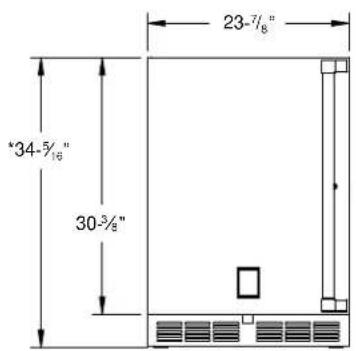
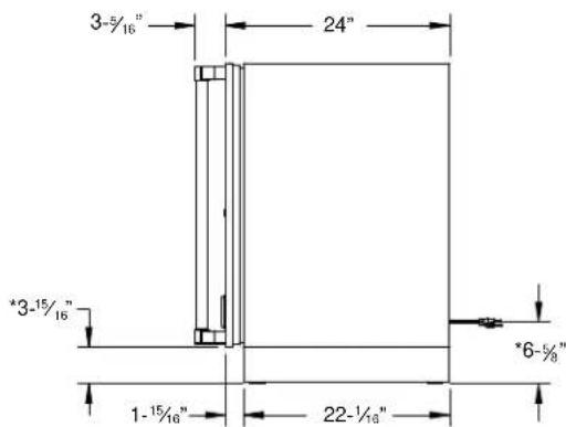
Leg levelers can add 3 / 4'' to these dimensions when fully extended.
| HEIGHT WIDTH | DEPTH | |
| 34-3/8" [87.3 cm] min.
35-1/2" [90.2 cm] max. | 24" [61 cm] 24" | [61 cm] |
-
Check that the following are level and square:
-
Front and interior opening
- Installation opening and floor surface
- Countertop bottom front edge
NOTE: The floor under the unit must be at the same level as surrounding finished floor.
CAUTION
To prevent possible damage to the countertop, do not place heavy objects on countertop directly over unit.
INSTALLING THE UNIT INTO THE SPACE INSTALLING THE UNIT INTO THE SPACE
-
Plug the unit into the 15 amp grounded electrical outlet located within the installation opening. With power applied to the unit, check that the lighting and cooling functions operate properly. Turn off the power to the wall outlet at the circuit breaker.
-
With all surfaces in the installation opening square and level, refer to Figure 2 below and perform the following steps to level the unit:
-
At the front of the opening, measure from the floor to the bottom of the front edge of the countertop.
Measure from the floor surface to the top of the unit at the rear corners.
- Adjust the unit legs so these two measurements are equal. Using an adjustable wrench or pliers, turn legs clockwise to lower the unit or counterclockwise to raise it.
NOTE: Legs should not extend more than 3 / 4'' [19 mm] from the bottom of the unit.
- Slide the unit into position in the opening. Make sure the rear leveling legs slide under the ant-tip brackets. Push the unit into the opening until the bottom front edge of the unit is flush with the surrounding cabinetry, or until the rear legs are tight against the anti-tip brackets.
- Shim the front of the unit so the front face is flush with the surrounding cabinetry. Adjust the front legs to support the countertop at the shimmed height. Using an adjustable wrench or pliers, turn the legs clockwise to lower the unit or counterclockwise to raise it. Countertop should be resting on top of the unit.
NOTE: Countertop should be resting evenly on entire top of the unit. Shim if necessary to prevent damage to the countertop.
- Check interior door openings to make sure the unit is level and square. Install shelving and/or drawers. For drawer units, place the slide brackets squarely into the bracket grooves. When installed properly, a "click" should be heard from the slide bracket retaining tabs and the brackets should slide smoothly. The retaining tabs will stop the shelf/drawer when pulled out to full extension.
- Turn on the power to the wall outlet at the circuit breaker.
NOTE: Improper shelf/drawer installation may not actuate slide mechanism.
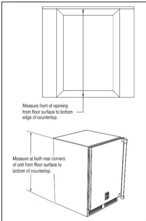
Figure 2. Leveling the Unit
INSTALLING THE FRONT GRILLE COVER INSTALLING THE FRONT GRILLE COVER
Once the unit is secured in place, install the louvered front grille cover. Secure the cover by snapping the latch into the latch catch on the unit (Figure 3).
The vent grille must be removed to service the unit. The floor cannot interfere with removal, and the louvered sections must not be covered or obstructed. Obstructions could prevent proper air circulation, which may damage the unit.
NOTE: To achieve maximum performance, interior Louver openings and fan guard openings should never be obstructed.
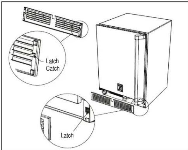
Figure 3. Front Grille Cover Installation
SHELVING/DRAWERADJUSTMENTSSHEL
CAUTION
Completely empty shelf or drawer before removing.
- Pull the shelf/drawer out to its furthest position. Locate the tabs in the middle of both extenders. Lift one tab up while pushing the opposite tab down, and pull shelf/drawer out (Figure 4).
- Position each bracket separately. Grasp the middle of the bracket, pull the front end up and out, then forward to remove it.
- Place bracket at desired location. Push the bracket rear hook into the rear mounting slot, then set front of the bracket in the front slot.
- Repeat for other brackets.
- Push extenders completely into brackets. Align the shelf/drawer grooves with the extenders and slide completely into the unit.
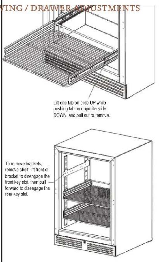
Figure 4. Shelving/Drawer Adjustment
DOOR OPTIONS DOOR OPTIONS
Hestan residential units can be converted from stainless steel to overlay panels to match existing cabinetry. Solid stainless steel and stainless steel glass doors are shipped from the factory with decorative stainless steel panels and handles in place on the unit. All stainless steel doors and drawers are convertible to fully integrated models, ready to accept custom panels from your cabinetry supplier. You can contact Hestan Customer Care to send you any of the following templates, or download directly from the Hestan website at www.hestanoutdoor.com.
028370 - Template, Overlay, 24" Solid Door, Undercounter Refrigeration
028371 - Template, Overlay, 24" Toe Kick/Grille, Undercounter Refrigeration
028372 - Template, Overlay, 24" Glass Door, Undercounter Refrigeration
028373 - Template, Overlay, 24" Solid Printer, Undercounter Refrigeration
028374 - Installation Instructions, Overlay Door/Drawer, Undercounter Refrigeration
Take care in choosing the correct template for your specific unit. The original appliance handle or custom cabinet handle can be installed onto your overlay panel.
NOTE: Glass with stainless steel trim and glass with wood trim may sweat in conditions with relative humidity over 75% .
HANDLER INSTALLATIONHANDLE INSTALLATION
CAUTION
The handle mounting on the overlay panel should be mounted on the overlay only (not the actual door) to avoid damage to the factory door. Proper woodworking materials and equipment should be used to avoid damage or errors in workmanship.
- Handle must be attached to the overlay before mounting the overlay onto the door. Mark the rear of the overlay panel with handle fastening locations.
- Drill through the overlay panel at marked locations, taking care not to damage the panel.
- Countersink screw heads so that screw heads are flush with the back side of the panel. Attach the handle to the overlay panel.
DOOR LOCK INSTALLATIONDOOR LOCK INSTALLATION
CAUTION
Proper woodworking materials and equipment should be used to avoid damage or errors in workmanship.
NOTE: Lock installation information is available on the above-mentioned template drawings.
Take care in choosing the correct template for your specific model.
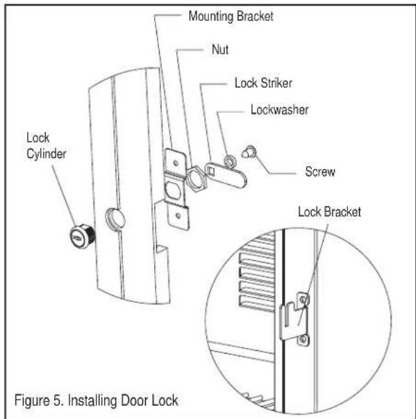
When installing to an overlay panel, perform the lock installation before mounting the overlay to the door!
- See Figure 5. Attach mounting bracket to overlay panel.
- Insert lock body and attach with nut. Reinstall remaining parts as shown.
OVERLAY INSTALLATIONOVERLAY INSTALLATION
Before beginning installation, check all components for proper fit and finish.
NOTE: For more detailed installation information, please request or download document 028374 mentioned on the previous page.
CAUTION
For best performance and functionality, the overlay panels should be 3/4'' [19 mm] thick. The weight of the overlays should not exceed 20 lbs [9 kg] for solid doors, 10 lbs [4.5 kg] for glass doors, or 10 lbs [4.5 kg] for drawer models.
- With the unit secured in position, open the door, CAREFULLY remove the door gasket (it can tear), and make sure panel pre-drilled holes align with door frame holes.
- Loosely attach four corners of overlay panel to the door using # 10 × 3 / 4 wood screws, installed through the door frame from the rear.
- Check the overall fit of the overlay panel, position, and function. Make minor adjustments as necessary. When panel is properly aligned, tighten mounting screws securely. Install the rest of the mounting screws and tighten securely.
CAUTION
Do not overtighten overlay panel attachment screws, as this may damage the factory supplied door frame.
WINE RACK TRIM (OPTIONAL) WINE RACK TRIM (OPTIONAL)
All wine reserve racks come with sleek stainless steel fronts, which can be removed and replaced with other wood to match your cabinetry. See Figure 6 for wine rack face details.
NOTE: The unfinished faces should be finished and sealed. In many cases, stains and / or finishes have odors that may be objectionable in an enclosed area. Do not stain or finish wood faces while installed on unit. To remove the front wood face from the wine shelf, simply pull out the wine shelf and remove the fasteners, finish as desired.
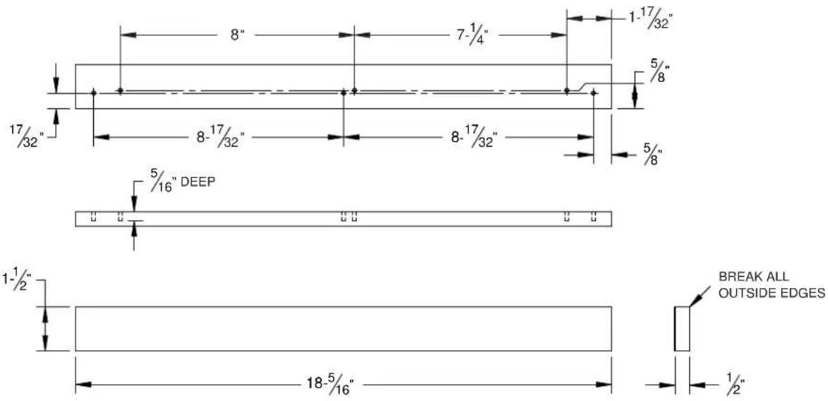
Figure 6. Wine Rack Trim
TABLES DES MATIERES
2 DÉFINITIONS DE SECURITÉ
3 NUMÉROS DE MODELE
4 PLAQUE SIGNALÉTIQUE
4 RESPECT DE LA RÉGLEMENTATION ET DES CODES EN VIGUEUR
4 SÉCURITÉ
6 INSTALLATION
10 INFORMATION SUR LA PORTE
LISEZ ATTENTIVEMENT ET COMPLETÉMENT CES INSTRUCTIONS AVANT D'INSTALLER OU D'UTILISER VOTRE APPAREIL AFIN DE RÉDUIRE LES RISQUES D'INCENDIE, DE BRULURE OU D'AUTRES BLESSURES. CONSERVER CE MANUEL POUR RÉFERENCE FUTURE.
Hestan Commercial Corporation
3375 E. La Palma Ave.
Anaheim, CA 92806
(888)905-7463