
Monteverde - Air Conditioning Klarstein - Free user manual and instructions
Find the device manual for free Monteverde Klarstein in PDF.

| Product type | Ceiling fan with light |
| Power supply | 220-240 V ~ 50-60 Hz |
| Motor power | 120-150 W |
| Bulb type | E27 |
| Maximum bulb wattage | 60 W |
| Maximum airflow | 139.6 m³/min |
| Number of speeds | 3 (slow, medium, high) |
| Remote control | Yes, included with timer |
| Adjustable timer | Yes |
| Minimum blade-to-floor distance | 2.3 m |
| Minimum suspension hook capacity | 100 kg |
| Use | Indoor only |
| Installation | Ceiling mounting, requires an omnipolar circuit breaker |
| Grounding required | Yes |
Frequently Asked Questions - Monteverde Klarstein
User questions about Monteverde Klarstein
0 question about this device. Answer the ones you know or ask your own.
Ask a new question about this device
Download the instructions for your Air Conditioning in PDF format for free! Find your manual Monteverde - Klarstein and take your electronic device back in hand. On this page are published all the documents necessary for the use of your device. Monteverde by Klarstein.
USER MANUAL Monteverde Klarstein
INHALTSVERZEICHNIS
flowchart
graph TD
    A["1H"] --> B["1:00"]
    B --> C["→"]
    C --> D["8:00"]
    E["2H"] --> F["2:00"]
    F --> G["→"]
    G --> H["8:00"]
    I["4H"] --> J["4:00"]
    J --> K["→"]
    K --> L["8:00"]
natural_image
Symbol of a trash bin crossed with a diagonal line, no text or numbers presentUnit 6 Riverside Business Centre
Brighton Road
Shoreham-by-Sea
BN43 6RE
United Kingdom
Dear Customer,
Congratulations on purchasing this device. Please read the following instructions carefully and follow them to prevent possible damages. We assume no liability for damage caused by disregard of the instructions and improper use. Scan the QR code to get access to the latest user manual and more product information.

CONTENT
Safety Instructions 14
Installation 15
Remote Control Buttons 19
Cleaning and Care 21
Troubleshooting 21
Disposal Considerations 22
Manufacturer & Importer (UK) 22
TECHNICAL DATA
| Item number 10035788 | |
| Power supply 220-240 V ~ 50-60 Hz | |
| Performance 120-150 W | |
| Lamp type E27 (max. 60 W) | |
| Maximum volume flow 139,6 m | ^3 /min |
SAFETY INSTRUCTIONS
- Never attach the fan to a power point, but to the ceiling itself.
- The minimum distance between the blades of the fan and the floor must be more than 2.3 m. The minimum carrying capacity of the hook from which the fan is hung must be 100 kg.
- Make sure to install all poles disconnection switch having a contact separation of at least 3 mm between poles in the supply wiring to the ceiling fan.
- The model or type reference of luminaries which may be installed in fans which are constructed for his purpose.
- Switch off the power before connecting.
- The electrical wiring must be in accordance with the local regulation.
- The fan must be properly earthed to avoid the risk of electric shocks.
- Never mount the fan in a moist or wet room.
- Be careful when working near the rotating blades.
- This device may be only used by children 8 years old or older and persons with limited physical, sensory and mental capabilities and / or lack of experience and knowledge, provided that they have been instructed in use of the device by a responsible person who understands the associated risks.
Note: Always have your fan installed by someone who is knowledgeable about electrical wiring.
Notes on load capacity and minimum distances
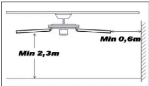
The minimum distance between the fan blades and the floor must be more than 2.3 m. The minimum load capacity of the hook on which the fan is suspended must be 100 kg.
INSTALLATION
| 1 | 2 |
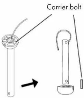 |  |
| Remove the carrier bolt from the hanging rod. | Put the hanging rod through the upper and lower cap. |
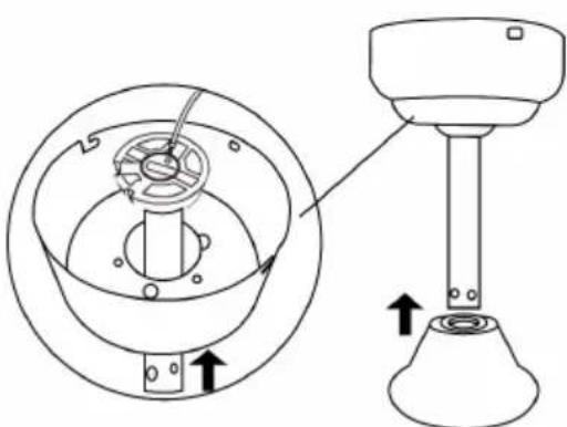
| 3 | |
 | |
| Feed the motor wires through the hanging rod. Reinsert the carrier bolt. Fasten the rod and the motor as shown with the screw, the two washers and the nut. | |
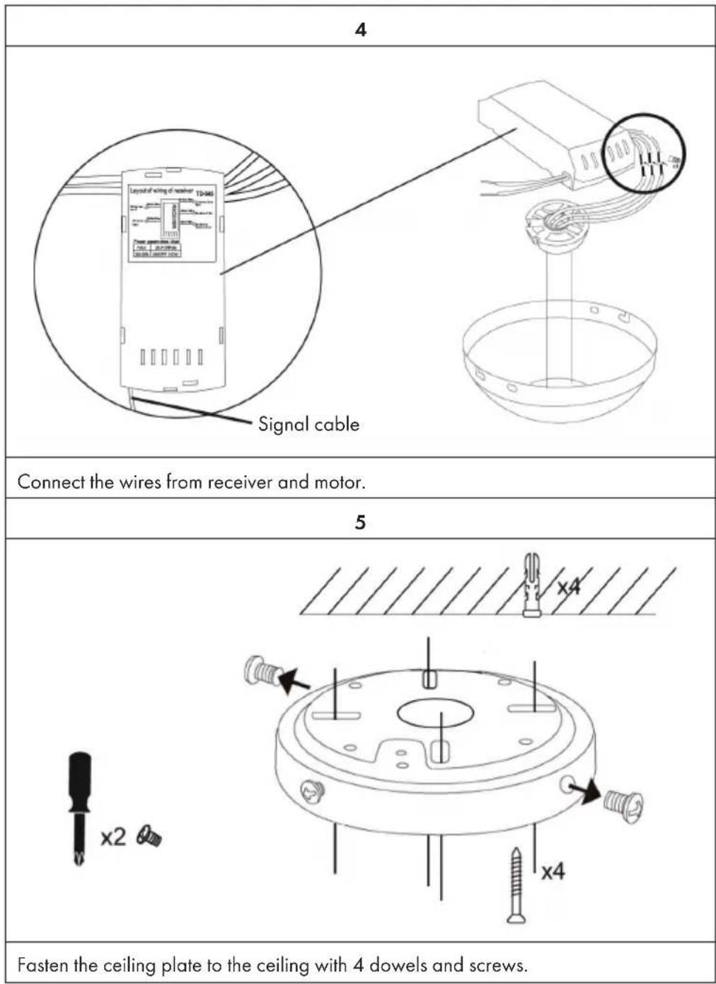
6
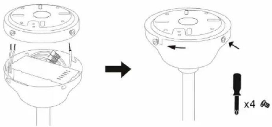
Insert the receiver and wires into the top cap. Fasten the top cap and ceiling plate with 4 screws.
7
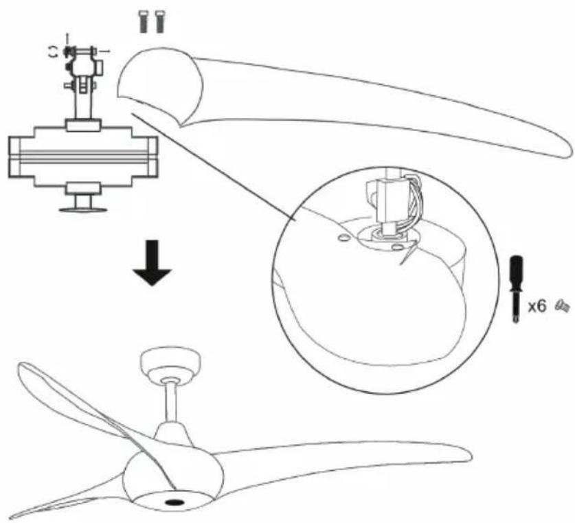
Fasten the rotor blades with 2 screws each.
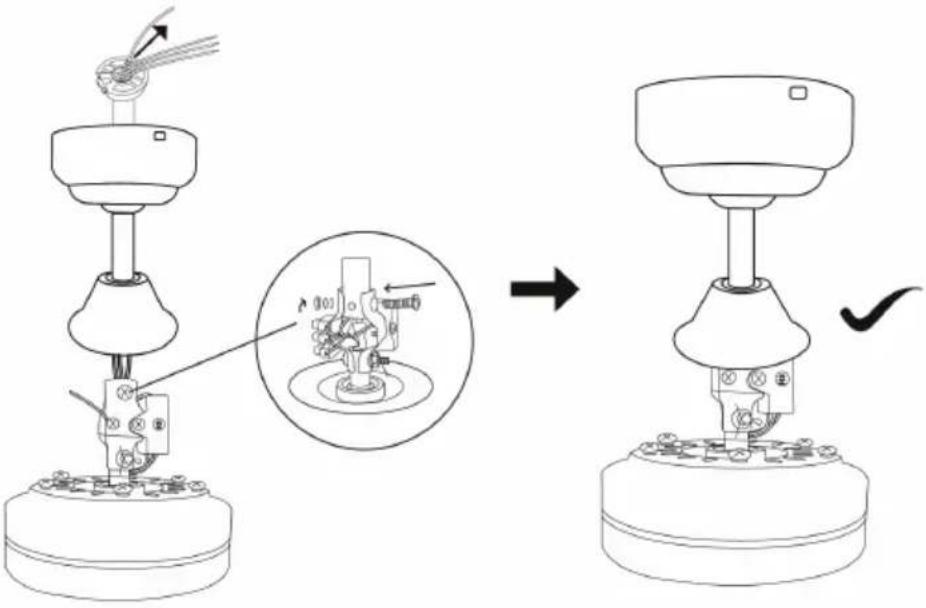
| 8 | |
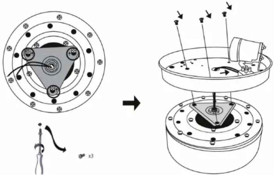 | |
| Loosen the screws from the triangular plate and fix the lamp holder plate. | |
| 9 10 | |
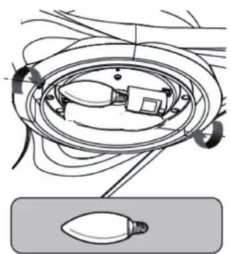 | 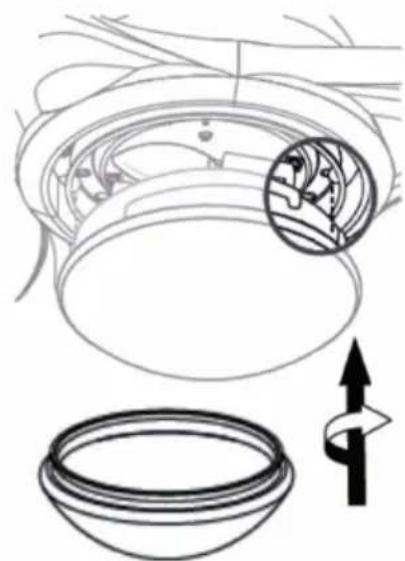 |
| Turn the bulb into the lamp socket. Turn the | glass attachment onto the lamp holder plate. The fan is now completely assembled and ready for use. |
REMOTE CONTROL BUTTONS
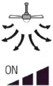
Speed and light
Press one of the buttons in the upper circle to adjust the speed and switch the light on or off.
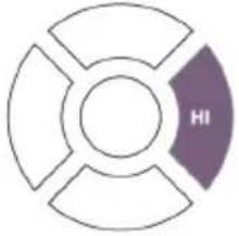  | 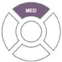 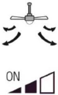 |
| High speed Medium speed | |
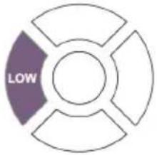 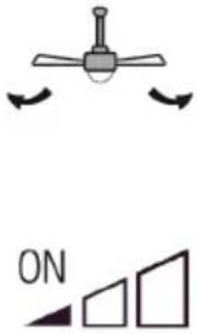 |  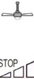 |
| Low speed Fan is off | |
 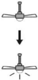 | |
| Light on/off |
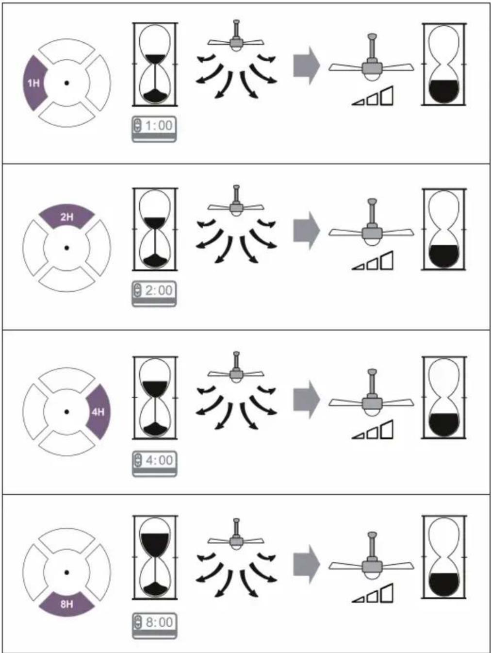
Timer
Press one of the buttons in the lower circle to set the timer. After the set time has elapsed, the fan will turn off automatically.
flowchart
graph TD
    A["1H"] --> B["1:00"]
    B --> C["→"]
    C --> D["8:00"]
    E["2H"] --> F["2:00"]
    F --> G["→"]
    G --> H["8:00"]
    I["4H"] --> J["4:00"]
    J --> K["→"]
    K --> L["8:00"]
CLEANING AND CARE
- Always disconnect the appliance from the power supply before cleaning the appliance or carrying out maintenance work.
- Never use a wet sponge to clean the appliance.
- In order not to damage the product, it is advisable to use equipment adapted to the sensitive surfaces and products, which will slow down the wear of the device.
TROUBLESHOOTING
| Problem Possible cause Approach | ||
| The fan does not start. | Fuse or circuit breaker blown. Check your fuses. | |
| Loose cable connections. Check all connections for loose cables. | ||
| Speed was not set correctly. Select a speed. | ||
| The fan makes noise. | The upper cap touches the ceiling. | Make sure there is a minimum distance of 3 mm between the top cap and the ceiling. |
| Screws of rotor blades are loose. | Tighten all screws. | |
| Ceiling fan is not properly attached to the ceiling. | Tighten all screws in the suspension plate. | |
| Speed is not adjusted correctly. | Select a speed. | |
| The fan is wobbling. | Rotor blades are not adjusted horizontally to the ceiling. | Move the fan so that all blades are at the same height to the ceiling. |
| Screws of the rotor blades are loose. | Tighten all screws. | |
DISPOSAL CONSIDERATIONS
natural_image
Symbol of a trash bin crossed with a diagonal line, no text or numbers presentIf there is a legal regulation for the disposal of electrical and electronic devices in your country, this symbol on the product or on the packaging indicates that this product must not be disposed of with household waste. Instead, it must be taken to a collection point for the recycling of electrical and electronic equipment. By disposing of it in accordance with the rules, you are protecting the environment and the health of your fellow human beings from negative consequences. For information about the recycling and disposal of this product, please contact your local authority or your household waste disposal service.
This product contains batteries. If there is a legal regulation for the disposal of batteries in your country, the batteries must not be disposed of with household waste. Find out about local regulations for disposing of batteries. By disposing of them in accordance with the rules, you are protecting the environment and the health of your fellow human beings from negative consequences.
MANUFACTURER & IMPORTER (UK)
Manufacturer:
Chal-Tec GmbH, Wallstrasse 16, 10179 Berlin, Germany.
Importer for Great Britain:
Chal-Tec UK limited
Unit 6 Riverside Business Centre
Brighton Road
Shoreham-by-Sea
BN43 6RE
United Kingdom
Estimado cliente,
ÍNDICE
flowchart
graph TD
    A["1H"] --> B["1:00"]
    B --> C["→"]
    C --> D["8:00"]
    E["2H"] --> F["2:00"]
    F --> G["→"]
    G --> H["8:00"]
    I["4H"] --> J["4:00"]
    J --> K["→"]
    K --> L["8:00"]
LIMPIEZA Y CUIDADO
natural_image
Symbol of a trash bin crossed with a diagonal line, no text or numbers presentUnit 6 Riverside Business Centre
Brighton Road
Shoreham-by-Sea
BN43 6RE
United Kingdom
Chère cliente, cher client,
SOMMAIRE
flowchart
graph TD
    A["1H"] --> B["1:00"]
    B --> C["→"]
    C --> D["8:00"]
    E["2H"] --> F["2:00"]
    F --> G["→"]
    G --> H["8:00"]
    I["4H"] --> J["4:00"]
    J --> K["→"]
    K --> L["8:00"]
NETTOYAGE ET ENTRETIEN
natural_image
Symbol of a trash bin crossed with a diagonal line, no text or numbers presentUnit 6 Riverside Business Centre
Brighton Road
Shoreham-by-Sea
BN43 6RE
United Kingdom
Gentile Cliente,
INDICE
natural_image
Symbol of a trash bin crossed with a diagonal line, no text or numbers presentPRODUTTORE E IMPORTATORE (UK)
Produttore:
Chal-Tec GmbH, Wallstraße 16, 10179 Berlino, Germania.
Unit 6 Riverside Business Centre
Brighton Road
Shoreham-by-Sea
BN43 6RE
United Kingdom

bar
| Category | Value | |---|---| | Category 1 | 100 | | Category 2 | 100 | | Category 3 | 100 | | Category 4 | 100 | | Category 5 | 100 | | Category 6 | 100 | | Category 7 | 100 | | Category 8 | 100 | | Category 9 | 100 | | Category 10 | 100 | | Category 11 | 100 | | Category 12 | 100 | | Category 13 | 100 | | Category 14 | 100 | | Category 15 | 100 | | Category 16 | 100 | | Category 17 | 100 | | Category 18 | 100 | | Category 19 | 100 | | Category 20 | 100 | | Category 21 | 100 | | Category 22 | 100 | | Category 23 | 100 | | Category 24 | 100 | | Category 25 | 100 | | Category 26 | 100 | | Category 27 | 100 | | Category 28 | 100 | | Category 29 | 100 | | Category 30 | 100 | | Category 31 | 100 | | Category 32 | 100 | | Category 33 | 100 | | Category 34 | 100 | | Category 35 | 100 | | Category 36 | 100 | | Category 37 | 100 | | Category 38 | 100 | | Category 39 | 100 | | Category 40 | 100 | | Category 41 | 100 | | Category 42 | 100 | | Category 43 | 100 | | Category 44 | 100 | | Category 45 | 100 | | Category 46 | 100 | | Category 47 | 100 | | Category 48 | 100 | | Category 49 | 100 | | Category 50 | 100 | | Category 51 | 100 | | Category 52 | 100 | | Category 53 | 100 | | Category 54 | 100 | | Category 55 | 100 | | Category 56 | 100 | | Category 57 | 100 | | Category 58 | 100 | | Category 59 | 100 | | Category 60 | 100 | | Category 61 | 100 | | Category 62 | 100 | | Category 63 | 100 | | Category 64 | 100 | | Category 65 | 100 | | Category 66 | 100 | | Category 67 | 100 | | Category 68 | 100 | | Category 69 | 100 | | Category 70 | 100 | | Category 71 | 100 | | Category 72 | 100 | | Category 73 | 100 | | Category 74 | 100 | | Category 75 | 100 | | Category 76 | 100 | | Category 77 | 100 | | Category 78 | 100 | | Category 79 | 100 | | Category 80 | 100 | | Category 81 | 100 | | Category 82 | 100 | | Category 83 | 100 | | Category 84 | 100 | | Category 85 | 100 | | Category 86 | 100 | | Category 87 | 100 | | Category 88 | 100 | | Category 89 | 100 | | Category 90 | 100 | | Category 91 | 100 | | Category 92 | 100 | | Category 93 | 100 | | Category 94 | 100 | | Category 95 | 100 | | Category 96 | 100 | | Category 97 | 100 | | Category 98 | 100 | | Category 99 | 100 | | Total (Total) = [sum of bars] / [values] * (sum of bars + bars) * (sum of bars + bars) * (sum of bars + bars). The values in the table represent the sum of the bars and the corresponding sum of the bars. There is no additional data series or categories specified in the code.
KLARSTEIN

- INHALTSVERZEICHNIS
- Dear Customer,
- CONTENT
- SAFETY INSTRUCTIONS
- Notes on load capacity and minimum distances
- INSTALLATION
- REMOTE CONTROL BUTTONS
- Speed and light
- Timer
- CLEANING AND CARE
- DISPOSAL CONSIDERATIONS
- MANUFACTURER & IMPORTER (UK)
- Manufacturer:
- Importer for Great Britain:
- Estimado cliente,
- ÍNDICE
- LIMPIEZA Y CUIDADO
- SOMMAIRE
- NETTOYAGE ET ENTRETIEN
- Gentile Cliente,
- INDICE
- PRODUTTORE E IMPORTATORE (UK)
- Produttore:
- KLARSTEIN
Brand : Klarstein
Model : Monteverde
Category : Air Conditioning