
W10495947 - Microwaves MAYTAG - Free user manual and instructions
Find the device manual for free W10495947 MAYTAG in PDF.

| Product Type | Built-in microwave oven combined with conventional oven |
| Brand | Maytag |
| Model | W10495947 |
| Dimensions (27" models) | Overall height 42 3/4" (108 cm), Width 27" (68.6 cm), Depth 23 1/4" (59.1 cm) |
| Dimensions (30" models) | Overall height 42 9/16" (108 cm), Width 30" (76.2 cm), Depth 23 1/4" (59.1 cm) |
| Minimum cutout opening (27") | Width 25 1/2" (64.8 cm), Height 41 5/16" (105 cm), Depth 24" (60.7 cm) |
| Minimum cutout opening (30") | Width 28 1/2" (72.4 cm), Height 41 5/16" (105 cm), Depth 24" (60.7 cm) |
| Weight (27" models) | 208 lb (95 kg) |
| Weight (30" models) | 249 lb (113 kg) |
| Power Supply | Dedicated electrical connection (see manual for exact specifications) |
| Main Functions | Microwave cooking, conventional cooking, combination |
| Safety | Door lock, safety alert symbol, DANGER/WARNING instructions |
| Maintenance and Cleaning | Clean with a damp cloth, avoid abrasives |
| Provided Parts | Leveling feet (front/rear), screws, vent trim |
| Repairability | Door removal possible, adjustable feet |
| General Information | Built-in installation, requires two people to move |
Frequently Asked Questions - W10495947 MAYTAG
User questions about W10495947 MAYTAG
0 question about this device. Answer the ones you know or ask your own.
Ask a new question about this device
Download the instructions for your Microwaves in PDF format for free! Find your manual W10495947 - MAYTAG and take your electronic device back in hand. On this page are published all the documents necessary for the use of your device. W10495947 by MAYTAG.
USER MANUAL W10495947 MAYTAG
LEVELING FEET INSTALLATION INSTRUCTIONS 27" (68.6 CM) AND 30" (76.2 CM) ELECTRIC BUILT-IN MICROWAVE/OVEN COMBINATION
INSTRUCTIONS D'INSTALLATION DES PIEDS DE NIVELLEMENT FOUR CONVENTIONNEL ET FOUR À MICRO-ONDES ÉLECTRIQUES, COMBINÉS ET ENCASTRÉS DE 27" (68,6 CM) ET 30" (76,2 CM)
Table of Contents/Table des matières
BUILT-IN MICROWAVE/OVEN COMBINATION SAFETY......2
INSTALLATION REQUIREMENTS....2
Tools and Parts 2
Built-In Microwave/Oven Combination
Location Requirements....3
LEVELING FEET INSTALLATION INSTRUCTIONS......4
Prepare Built-In Microwave/Oven Combination....4
Remove Oven Door....4
Positioning Oven Feet for Multiple Cabinet
Cutout Heights 4
SÉCURITÉ DU FOUR À MICRO-ONDES ET DU FOUR CONVENTIONNEL COMBINÉS ET ENCASTRÉS....7
Your safety and the safety of others are very important.
We have provided many important safety messages in this manual and on your appliance. Always read and obey all safety messages.

This is the safety alert symbol.
This symbol alerts you to potential hazards that can kill or hurt you and others.
All safety messages will follow the safety alert symbol and either the word "DANGER" or "WARNING."
These words mean:
DANGER
You can be killed or seriously injured if you don't immediately follow instructions.
WARNING
You can be killed or seriously injured if you don't follow instructions.
All safety messages will tell you what the potential hazard is, tell you how to reduce the chance of injury, and tell you what can happen if the instructions are not followed.
INSTALLATION REQUIREMENTS
Tools and Parts
Gather the required tools and parts before starting installation. Read and follow the instructions provided with any tools listed here.
Tools needed
■ Phillips screwdriver
■ Measuring tape
■ Level
■ Flat-blade screwdriver
Parts supplied
■ Four #8-18 x 12 " screws - oven feet
■ Bottom vent trim
■ Two rear feet (Part Number W10318219)
■ Two front feet (Part Numbers W10471952 and W10471956)
Built-In Microwave/Oven Combination Location Requirements
IMPORTANT: Observe all governing codes and ordinances.
■ Cabinet opening dimensions that are shown must be used. Given dimensions provide minimum clearance with oven.
■ Recessed installation area must provide complete enclosure around the recessed portion of the oven.
■ Grounded electrical supply is required. See "Electrical Requirements" section.
■ Electrical supply junction box should be located 3" (7.6 cm) maximum below the support surface when the oven is installed in a wall cabinet. A 1" (2.5 cm) minimum diameter hole should have been drilled in the left rear corner of the support surface to pass the appliance cable through to the junction box.
■ Oven support surface must be solid, level and flush with bottom of cabinet cutout. Floor must be able to support a total weight (microwave and built-in oven) of 208 lbs (95 kg) for 27" (68.6 cm) models or 249 lbs (113 kg) for 30" (76.2 cm) models.
IMPORTANT: To avoid damage to your cabinets, check with your builder or cabinet supplier to make sure that the materials used will not discolor, delaminate or sustain other damage. This oven has been designed in accordance with the requirements of UL and CSA International and complies with the maximum allowable wood cabinet temperatures of 194°F (90°C).
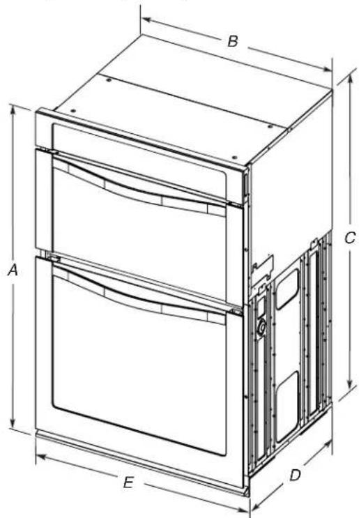
Product Dimensions
27" (68.6 cm) and 30" (76.2 cm) Ovens
text_image
A B C D E27" (68.6 cm) models
A. 42% (108.0 cm) overall height
B. 25/16" (64.6 cm) recessed width
C. 41" (104.1 cm) recessed height
D. 23¼" (59.1 cm) max. recessed depth
E. 27" (68.6 cm) overall width
30" (76.2 cm) models
A. 42%6" (108.0 cm) overall height
B. 28½" (72.3 cm) recessed width
C. 41" (104.1 cm) recessed height
D. 23½" (59.1 cm) max. recessed depth
E. 30" (76.2 cm) overall width
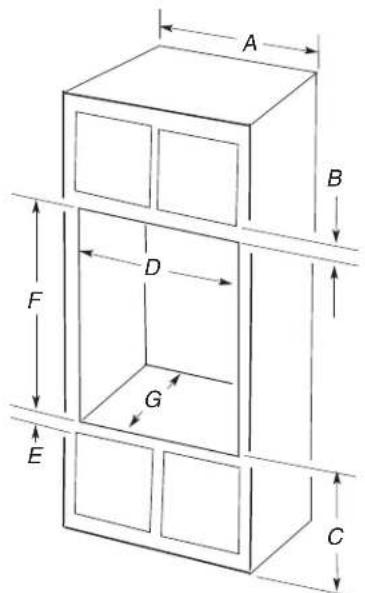
Cabinet Dimensions
27" (68.6 cm) and 30" (76.2 cm) Ovens
text_image
A B D G F E C27" (68.6 cm) models
A. 27" (68.6 cm) min. cabinet width
B. 1" (2.5 cm) top of cutout to bottom of upper cabinet door
C. 19 ^1/4 " (48.9 cm) bottom of cutout to floor is recommended.
4"-19 ^1/4 " (10.2-48.9 cm) bottom of cutout to floor is acceptable.
D. 25½" (64.8 cm) cutout width
E. 1 ½" (3.8 cm) min. bottom of cutout to top of cabinet door
F.41 516 " (105 cm) ^* recommended cutout height
G. 24" (60.7 cm) cutout depth
30" (76.2 cm) models
A. 30" (76.2 cm) min. cabinet width
B. 1" (2.5 cm) top of cutout to bottom of upper cabinet door
C. 19 ^1/4 " (48.9 cm) bottom of cutout to floor is recommended.
4"-19 ^1/4 " (10.2-48.9 cm) bottom of cutout to floor is acceptable.
D. 28½" (72.4 cm) cutout width
E. 1 ½" (3.8 cm) min. bottom of cutout to top of cabinet door
F.41 516 " (105 cm) ^* recommended cutout height
G. 24" (60.7 cm) cutout depth
*NOTE: The cabinet height can be between 41" to 42 14 " (104.1 cm to 107.3 cm) or 42 78 " to 43 516 " (108.9 cm to 110.0 cm) for microwave/oven combination.
LEVELING FEET INSTALLATION INSTRUCTIONS
Prepare Built-In Microwave/Oven Combination
- Decide on the final location for the oven. Locate existing wiring to avoid drilling into or severing wiring during installation.
WARNING
Excessive Weight Hazard
Use two or more people to move and install oven.
Failure to do so can result in back or other injury.
- To avoid floor damage, set the oven onto cardboard prior to installation. Do not use handle or any portion of the front frame for lifting.
- Remove the shipping materials and tape from the oven.
- Remove the hardware package from inside the bag containing literature.
- Remove and set aside racks and other parts from inside the oven.
- Move oven and cardboard close to the oven's final location.
Remove Oven Door
IMPORTANT: Use both hands to remove oven door(s).
- Open the oven door.
- Locate the oven door latches in both corners of the oven door, and rotate the latches forward to the unlocked position.
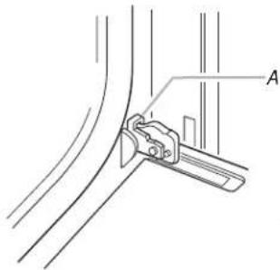
natural_image
Technical line drawing of a mechanical clamp or bracket assembly (no text or symbols)A. Oven door latch in locked position
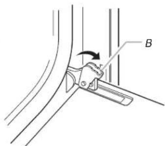
text_image
Technical diagram showing a hand operating a lever labeled B with an arrow indicating motion directionB. Oven door latch in unlocked position
- Grasp the edges of the oven door with both hands and close the oven door until it will no longer close. Lift and pull oven door toward you and remove. Set the oven door aside on a covered work surface.
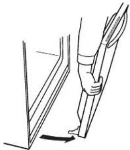
natural_image
Line drawing of a person using a tool to lift or stand (no text or symbols)Positioning Oven Feet for Multiple Cabinet Cutout Heights
Combo Ovens
The positioning of the oven feet allow a combo oven to be installed in a cutout height between 41 ^1/8 " (104.5 cm) and 43 ^5/16 " (110.0 cm). Refer to the following instructions to position the feet for the size of your cabinet cutout.
Cutout height is between 41½" (104.5 cm) and 41½" (105.5 cm)
The oven feet do not need to be changed. The combo is configured correctly as received.
NOTE: Do not remove the spacers.
Go to the "Make Electrical Connection" section of the Installation Instructions that came with the product.
natural_image
Technical line drawing of an oven with internal compartments and labeled parts (A), no text or symbols present.A. Spacers
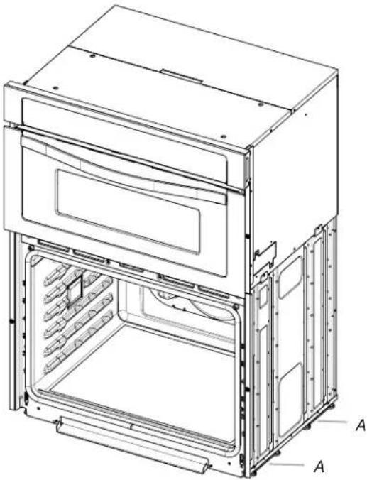
Cutout Height is between 41^13/16 (106.2 cm) and 42^1/4 (107.3 cm)
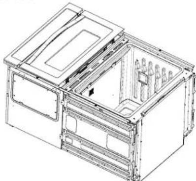
- Using 2 or more people, place the combo oven on its back on a covered surface.

natural_image
Technical line drawing of a modular device with internal compartments and mounting brackets (no text or symbols)- Install one of the rear feet (Part Number W10318219) on the left rear spacer using a #8-18 x 1/2" screw.
NOTE: Position the rear foot so the long side of the foot is facing toward the top of the oven.
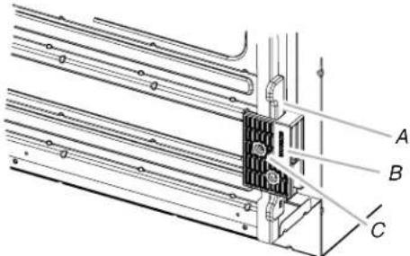
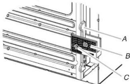
text_image
Technical diagram of a structural assembly with labeled components A, B, and CA. Spacer
B. Rear foot
C. #8-18 x 1/2" screw
- In the same manner, install the other rear foot (Part Number W10318219) on the right rear of the oven.
- Install the front foot (Part Number W10471952) on the left front spacer using a #8-18 x 1/2" screw.
NOTE: Position the front foot so the long side of the foot is facing toward the inside of the oven.
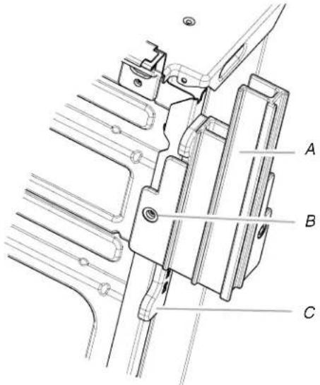
text_image
A B CA. Front foot
B. #8-18 x 1/2" screw
C. Spacer
- In the same manner, install the front foot (Part Number W10471956) on the right front of the oven.
- Using 2 or more people, place the oven in its upright position.
natural_image
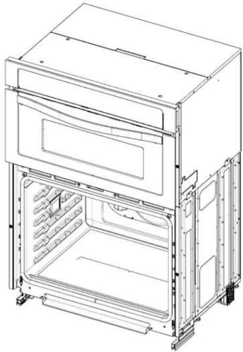
Technical line drawing of an oven with internal compartments and ventilation slots (no text or symbols)- Go to the "Make Electrical Connection" section of the Installation Instructions that came with the product.
Cutout Height is between 42 ^7/8 " (108.9 cm) and 43 ^5/16 " (110.0 cm)
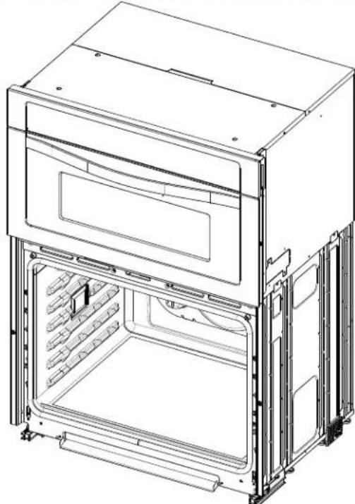
- Using 2 or more people, place the oven on its back on a covered surface.
natural_image
Technical line drawing of a mechanical housing or enclosure with internal compartments and mounting brackets (no text or symbols)- Install one of the rear feet (Part Number W10318219) on the left rear spacer using a #8-18 x 1/2" screw.
NOTE: Position the rear foot so the short side of the foot is facing toward the top of the oven.
text_image
Technical diagram of a mechanical assembly with labeled components A, B, and CA. Spacer
B. Rear foot
C. #8-18 x ½" screw
- In the same manner, install the other rear foot (Part Number W10318219) on the right rear of the oven.
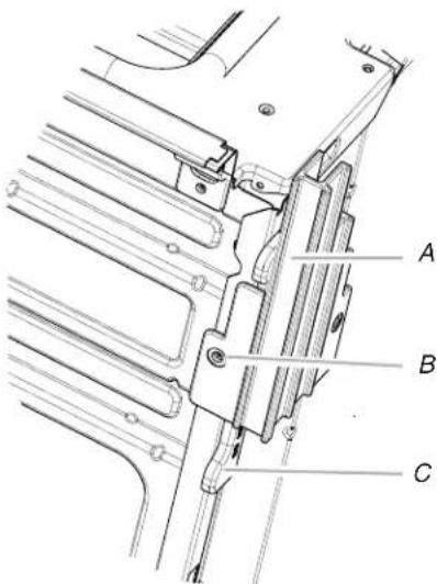
- Install the front foot (Part Number W10471956) on the left front using a #8-18 x 1/2" screw. NOTE: Position the front foot so the long side of the foot is facing away from the oven as shown.
text_image
Technical diagram of a mechanical assembly with labeled parts A, B, and CA. Front foot
B. #8-18 x 12 " screw
C. Spacer
- In the same manner, install the front foot (Part Number W10471952) on the right front of the oven.
- Using 2 or more people, place the oven in its upright position.
natural_image
Technical line drawing of an oven with internal compartments and mounting base (no text or symbols)- Go to the "Make Electrical Connection" section of the Installation Instructions that came with the product.
SÉCURITÉ DU FOUR À MICRO-ONDES ET DU FOUR CONVENTIONNEL COMBINÉS ET ENCASTRÉS
text_image
A B D F G E Cnatural_image
Technical line drawing of a mechanical clamp or bracket assembly (no text or symbols)text_image
Technical diagram showing a mechanical joint or bracket with labeled component B and directional arrow indicating rotation or movement.natural_image
Line drawing of a person using a tool to lift or lift a wall, showing the angle of change (no text or symbols)natural_image
Technical line drawing of an oven with internal compartments and labeled parts (A), no text or symbols present.A. Cales d'espacement