DOM16A2SSDB - Cooker DANBY - Free user manual and instructions
Find the device manual for free DOM16A2SSDB DANBY in PDF.

| Product Type | Built-in microwave (integrated hood) |
| Brand | Danby |
| Model | DOM16A2SSDB |
| Dimensions (W x H x D) | 30" x 16 1/2" x 15 1/2" (approx.) |
| Weight | 22.6 to 31.7 kg (50-70 lb) |
| Power Supply | 120 V, 60 Hz, 3-prong grounded plug |
| Microwave Power | 1000 W (estimate) |
| Capacity | 1.6 cu. ft. (estimate) |
| Exterior Material | Stainless steel |
| Ventilation Types | External top exhaust, external rear exhaust, recirculation |
| Main Functions | Microwave cooking, two-stage cooking, cooking sensor (pizza, potato, meat, reheat, popcorn, beverage, vegetables), defrost by weight, by time and 1 lb, add 30 seconds, timer, auto stop |
| Controls | Numeric keypad, clock, power, light, ventilation, eco, child lock buttons |
| Interior Lighting | Replacement bulb max 30 W |
| Grease Filters | Monthly cleaning, washable with warm water and mild detergent |
| Charcoal Filter | For recirculation installation, replace every 6-12 months |
| Cleaning | Interior and exterior with damp cloth and mild detergent, glass tray and roller ring dishwasher safe |
| Safety | Child lock, mandatory grounding, liquid overheating protection, spark detection |
| Spare Parts | Glass tray, roller support, grease filter, charcoal filter, light bulb |
| Warranty | 18 months functional parts, 30 days plastic parts |
| General Information | Installation above a range (max 36" wide), requires at least one wall stud, do not use an extension cord |
Frequently Asked Questions - DOM16A2SSDB DANBY
- Defrost by Weight: press 'Defrost by Weight', enter weight in ounces (max 96), press Start. Turn food over when unit beeps.
- 1 lb Defrost: for one pound quickly.
- Defrost by Time: press 'Defrost by Time', enter time (max 99:99), press Start.
User questions about DOM16A2SSDB DANBY
0 question about this device. Answer the ones you know or ask your own.
Ask a new question about this device
Download the instructions for your Cooker in PDF format for free! Find your manual DOM16A2SSDB - DANBY and take your electronic device back in hand. On this page are published all the documents necessary for the use of your device. DOM16A2SSDB by DANBY.
USER MANUAL DOM16A2SSDB DANBY
Do the right thing\*
MODEL • MODÈLE
DOM16A2SSDB
OWNER'S MANUAL......1 - 31
MANUEL DU PROPRIÉTAIRE......32 - 62
Danby Products Limited, Guelph, Ontario, Canada N1H 6Z9
Danby Products Inc. Findlay, Ohio, U.S.A. 45840
www.Danby.com

This equipment generates and uses ISM frequencies and if not installed and used properly in strict accordance with the manufacturer's instructions, it may cause interference to radio and television reception. It has been type-tested and found to comply with limits for ISM Equipment pursuant to Part 18 of FCC Rules, which are designed to provide reasonable protection against such interference in a residential installation.
However, there is no guarantee that interference will not occur in particular installations. If this equipment does cause interference to radio or television reception, which can be determined by turning the equipment off and on, the interference can be corrected by one or more of the following methods:
- Reorient the receiving antenna of radio or television.
- Move the microwave oven away from the receiver.
- Plug the microwave into a different outlet so that microwave and receiver are on different branch circuits.
The manufacturer is not responsible for any radio or TV interference caused by unauthorized modification of this appliance. It is the responsibility of the user to correct such interference.
AVOID POSSIBLE EXPOSURE TO EXCESSIVE MICROWAVE ENERGY
- Do not attempt to operate the appliance with the door open as this can result in harmful exposure to microwave energy. Do not tamper with or attempt to defeat the safety locks.
- Do not place any object between the front face and the door or allow soil or cleaner residue to accumulate on the sealing surfaces.
- Do not operate the appliance if it is damaged. The door must close properly and there must be no damage to the hinges, latches, door, door seals or sealing surfaces.
SAVE THESE INSTRUCTIONS!
GROUNDING INSTRUCTIONS
This appliance must be grounded. In the event of an electrical short circuit, grounding reduces the risk of electrical shock by providing an escape wire for the electrical current.
This appliance is equipped with a cord that has a grounding wire with a grounding plug. The power cord must be plugged into an outlet that is properly grounded. If the outlet is a standard 2-prong wall outlet, it is your responsibility to have it replaced with a properly grounded 3-prong wall outlet. The serial rating plate indicates the voltage and frequency the appliance is designed for.
WARNING - Improper use of the grounding plug can result in a risk of electric shock. Consult a qualified electrician or service agent if the grounding instructions are not completely understood, or if doubt exists as to whether the appliance is properly grounded.
DO NOT USE AN EXTENSION CORD
Do not connect your appliance to extension cords or together with another appliance in the same wall outlet. Do not splice the power cord. Do not under any circumstances cut or remove the third ground prong from the power cord.
If the power supply cord is damaged, it must be replaced by the manufacturer, its service agent or similar qualified person in order to avoid hazard.
SAFETY REQUIREMENTS
- Ensure that component parts are replaced with like components and that servicing is done by factory authorized service personnel, to minimize the risk of possible ignition due to incorrect parts or improper service.
- Check the appliance for damage before using. If there is any damage to the appliance, do not use it, return it to its point of purchase or contact consumer care.
- Do not clean this appliance with or use near combustible materials.
- Children should be supervised to ensure that they do not play with the appliance.
- This appliance is specifically designed to heat, cook or dry food. It is not designed for industrial or laboratory use.
- Do not store or use this appliance outdoors. Do not use this appliance near water.
- Do not overcook food. Carefully watch the appliance when it is in use.
- Remove wire twist-ties before placing items in the appliance.
- Do not use the appliance for storage purposes. Do not leave items inside the appliance when not in use.
- Do not heat oil or fat for deep frying as it is difficult to control the temperature of oil in a microwave.
- Some items such as whole eggs or sealed containers have the possibility of exploding when heated and should not be placed in this appliance.
- Ensure that the glass tray and rollers are in the correct position before use to avoid possible spills.
- Do not operate this appliance when it is empty as this will increase the heat around the magnetron and can damage the appliance or cause a fire.
- If items inside the appliance should ignite, keep the door closed, turn the appliance off and disconnect the power cord.
- Do not operate the appliance without the glass tray, roller support and shaft in their correct positions.
SAFETY - SUPERHEATED LIQUID
Liquids are able to be overheated beyond the boiling point without appearing to be boiling due to the surface tension of the liquid. Visible bubbling will not always be present when the liquid is removed from the appliance. This could result in very hot liquids suddenly boiling over when a utensil or other item such as a tea bag is inserted into the liquid.
To reduce the risk of injury:
- Do not overheat liquids. Do not heat any liquid for more than 2 minutes per cup.
• Stir liquids before and halfway through heating.
- Do not use straight-sided containers with narrow necks as this can cause a build up of steam.
- Superheated liquid can begin to spontaneously boil when removed from the microwave. After heating, allow the liquid to stand in the microwave for 30 seconds before removing.
- Use extreme care when inserting a utensil or other item into hot liquids.
- The contents of milk bottles and baby food jars should be stirred or shaken and the temperature checked before serving in order to avoid burns.
- Do not defrost frozen beverages, especially carbonated beverages, in this appliance as they could explode.
- Hot foods and steam can cause burns. Be careful when opening any container that has been heated in the appliance. Direct the opening away from hands and face to avoid burns.
SAFETY - ARCING
Arcing refers to sparks inside the microwave while it is in operation. Arcing is caused by:
• Metal or foil inside the appliance.
• Recycled paper towels being used inside the appliance, as these can contain small pieces of metal.
If arcing is present, stop operation and remove any metal or paper towels from the appliance.
INSTALLATION INSTRUCTIONS
INSTALLATION
- Remove all packing materials from the inside and outside of the appliance. Do not remove the cardboard mica sheet covering the magnetron.
- Check the appliance for damage before using, such as a misaligned or bent door, damaged door seals, broken or loose door hinges or latches, or dents inside the cavity or on the door. If there is any damage to the appliance, do not use it, return it to its point of purchase or contact consumer care.
- The mounting surface must be capable of supporting the cabinet load in addition to the added weight of this microwave, approximately 22.6 - 31.7 kg (50 - 70 pounds), plus additional oven loads of up to 22.6 kg (50 pounds) for a total weight of 45.2 - 54.3 kg (100 - 120 pounds).
- This appliance cannot be installed in cabinet arrangements such as an island or peninsula. It must be mounted to both a top cabinet and a wall.
- Do not clean this appliance with or use near combustible materials.
- Do not block any ventilation openings on the appliance.
- Do not operate the appliance without the glass tray, roller support and shaft in their correct positions.
- Make sure the shelf is positioned properly inside the microwave to prevent damage from arcing. Do not use the microwave with the shelf on the floor of the microwave. Do not use the shelf when cooking popcorn. Always use pot holders when removing the shelf as it may be hot.
INSTALLATION INSTRUCTIONS
PARTS INCLUDED
| PART QTY | ||
 | Mounting plate | 1 |
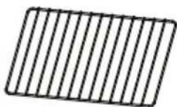 | Shelf 1 | |
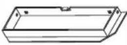 | Exhaust adapter | 1 |
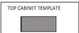 | Top cabinet template | 1 |
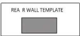 | Rear wall template | 1 |
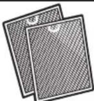 | Extra grease fi Iters | 1 |
INSTALLATION ACCESSORIES
| PART QTY | ||
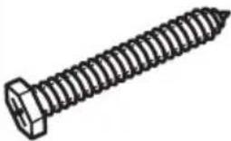 | Wood screw(1/4" x 2") | 2 |
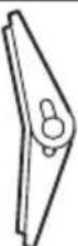 | Wing nut 2 | |
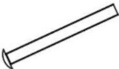 | Machinescrew(3/16" x 3") | 2 |
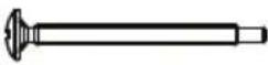 | Self aligningmachinescrew(1/4"-20 x3") | 2 |
 | Nylongrommet(for metalcabinets) | 1 |
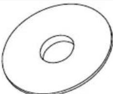 | Washer 2 | |
 | Sheet metalscrew | 2 |
INSTALLATION INSTRUCTIONS
REQUIRED TOOLS
• #1 and #2 Phillips head screwdrivers
- Pencil or pen
- Gloves
- Safety goggles
- Duct tape
- Masking tape
• Electric drill with 3/16", 1/2" and 5/8" bits
- Saber, hole or keyhole saw
- Level
• Ruler, tape measure or straight edge
• Carpenter square (optional)
- Edge to edge stud fi'nder or hammer (optional)
- Tin snips (to cut damper if necessary)
- Scissors (to cut template if necessary)
- Filler blocks or scrap wood pieces (for top cabinet spacing in recessed bottom cabinet installations if necessary)
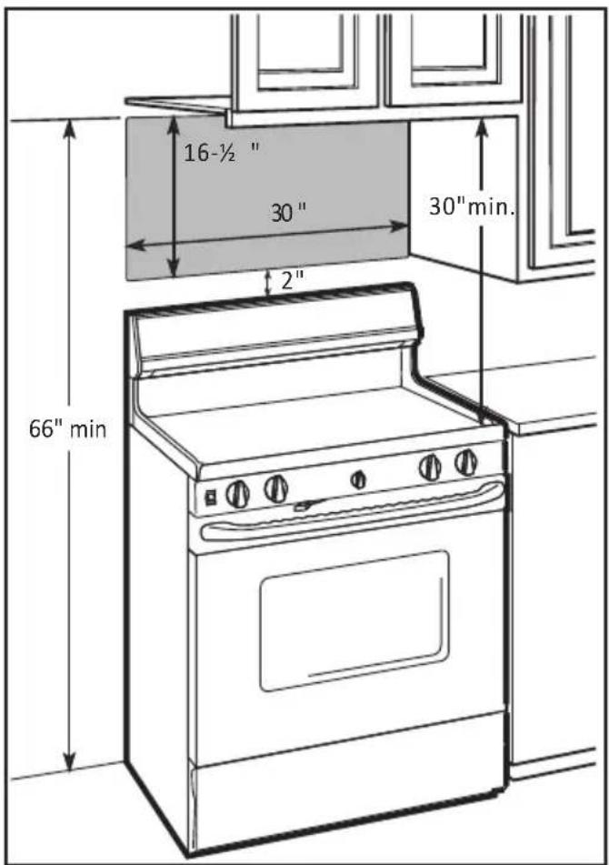
LOCATION
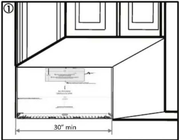
- The space between the cabinets must be 30" wide and free of obstructions.
- If the space between the cabinets is greater than 30", use fi ller material to fi ll the gap between the microwave oven and the cabinets.
- This microwave is for installation over ranges up to 36" wide.
- If installing the microwave beneath smooth, fl at cabinets, be sure to follow the instructions for power cord clearance.
INSTALLATION INSTRUCTIONS
UNPACKING THE APPLIANCE
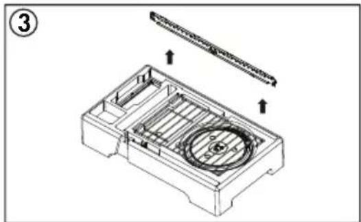
- Open the carton and remove the upper foam from the box. Keep the accessories.
- Remove the microwave from the carton and remove the plastic bag.
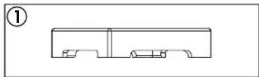
- Remove the mounting bracket from the upper foam.
natural_image
Pure technical line drawing of a mechanical part or housing without any text, numbers, or symbols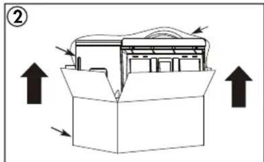

natural_image
Technical line drawing of a mechanical housing with internal components and directional arrows (no text or symbols)FINDING THE WALL STUDS
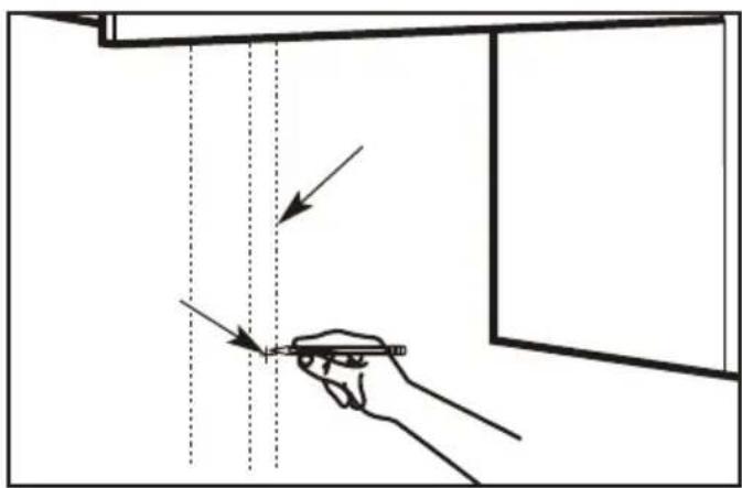
- Use a stud fi nder to locate the wall stud. If a stud fi nder is not available, use a hammer to tap lightly on the wall to fi nd a solid sound. This sound indicates the location of the wall stud.
- Find the center of the wall stud by probing the wall with a small nail to find the edges of the stud. Draw a line down the center of the wall stud.
Note: The microwave must be connected to at least one wall stud.
INSTALLATION INSTRUCTIONS
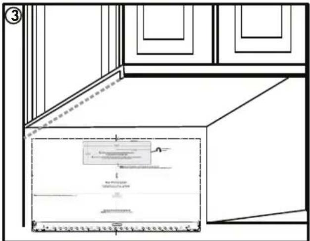
USING THE INSTALLATION TEMPLATE
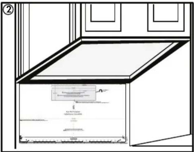
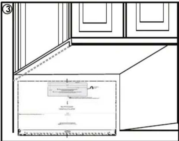
There are three different types of cabinetry that will change how the rear wall template should be used to determine where to install the mounting bracket.
- Flat bottomed cabinet: The top of the template should align with the bottom of the cabinet.
- Framed recessed cabinet: The top of the template should align with the back frame of the cabinet bottom.
- Framed recessed bottom cabinet with front overhang: The top of the template should align with the front overhang. It may be helpful to measure the overhang, then measure the same distance from the bottom of the cabinet and mark that spot.
Notes:
- Any decorative trim on the cabinetry or wall should be removed before installing the microwave.
- Use a level to ensure that the template is level before marking the wall. The microwave must be level to ensure proper functioning.
- At least three screws must be used to install the mounting plate. At least one of those screws must be in a wall stud.
INSTALLATION INSTRUCTIONS
- Tape the mounting template to the wall and then mark the three screw holes at the bottom of the template. Remove the template and double check the marked holes with the actual mounting plate to ensure that they match.
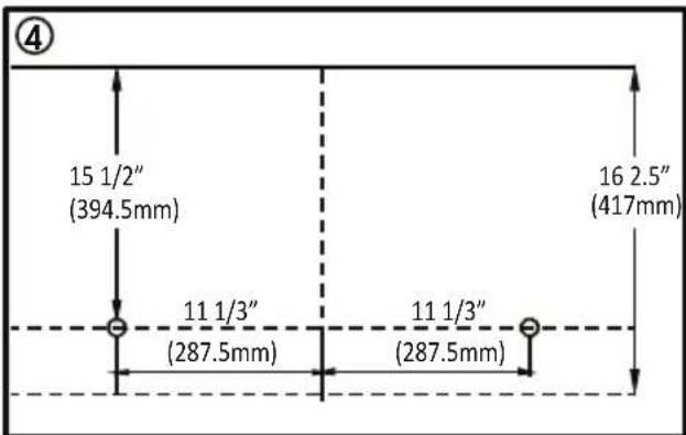
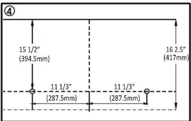
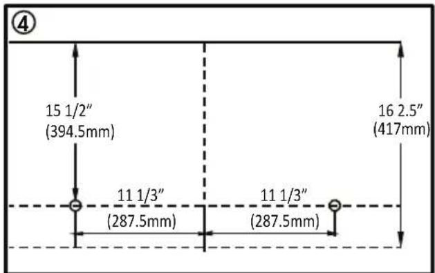
4. Template damaged or unusable
If the template arrives damaged or cannot be used, measure and mark the wall with these dimensions.
The bottom edge of the mounting plate must be 16 2/5" from the bottom edge of the upper cabinet.
The mounting plate holes must be 15 1/2" from the bottom edge of the upper cabinet and must be in line with each other. Each hole must be 11 1/3" from the center line.
Do not install the actual mounting plate yet, the exhaust duct work must be installed first.


INSTALLATION INSTRUCTIONS
HOOD EXHAUST
This microwave is designed for adaptation to three types of ventilation: outside top exhaust, outside back exhaust and non-venting ductless recirculation. Use the following duct instructions if the appliance will be vented to the outside.
For satisfactory air movement, the total duct length of 3 1/4" x 10" rectangular or 6" round duct should not exceed 140 equivalent feet.
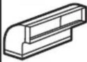
Elbows, transitions, wall caps and roof caps present additional resistance to airflow and are equivalent to a section of straight duct which is longer than the actual physical size. When calculating the total duct length add the equivalent lengths of all transitions and adapters plus the length of all straight duct sections. The chart below is an example of one possible installation configuration.
OUTSIDE TOP EXHAUST (EXAMPLE ONLY)
The following chart describes an example of one possible ductwork installation.
| DUCT PIECES EQUIVALENT | LENGTH | X | NUMBER USED | = | EQUIVALENT LENGTH | |
 | Roof cap | 24 ft X (1) = 2 | 4 ft | |||
| (DA67) | 12 ft. straight duct (6" round) | 12 ft X (1) = 1 | 2 ft | |||
| (TTT4) | Rectangular to round transition adapter | 5 ft X (1) = 5 ft | ||||
| TOTAL LENGTH | = 41 ft | |||||
IMPORTANT: If a rectangular to round transition adapter is used, the bottom corners of the damper must be cut to fit using tin snips to allow free movement of the damper.
IMPORTANT: It is important that venting be installed using the most direct route with as few elbows as possible. This ensures clear venting of exhaust and helps prevent blockages. Make sure dampers swing freely and nothing is blocking the ducts.
INSTALLATION INSTRUCTIONS
DUCT LENGTH CALCULATOR
Use the chart below to calculate the total length of the duct work being installed. The total length should not exceed 140 feet.
| DUCT PIECES EQUIVALE | NT LENGTH | X | NUMBER USED | = | EQUIVALENT LENGTH | |
 | Rectangular to round transition adapter | 5 ft X ( | ) = ft | |||
 | Wall cap | 40 ft X ( | ) = ft | |||
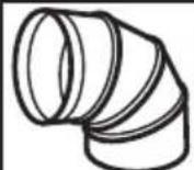 | Round 90° elbow | 10 ft X ( | ) = ft | |||
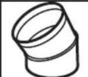 | Round 45° elbow | 5 ft X ( | ) = ft | |||
 | Rectangular 90° elbow | 25 ft X ( | ) = ft | |||
 | Rectangular 45° elbow | 5 ft X ( | ) = ft | |||
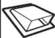 | Roof cap | 24 ft X ( | ) = ft | |||
| (HHOK) | Straight duct 6" round or 3 1/4" x 10" rectangular | 1 ft X ( | ) = ft | |||
| TOTAL LENGTH | = | f | ||||
INSTALLATION INSTRUCTIONS
OUTSIDE TOP EXHAUST
Use these instructions if the appliance will be vented to the outside through the top of the appliance.
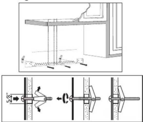
Install the mounting plate
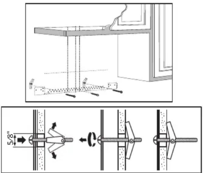
Use a 5/8" drill to make two holes that will enter the drywall. Use a 3/16" drill to make a hole that will enter a wall stud. Use the mounting template to decide the location of the holes. At least one hole must enter a wall stud.
Insert the machine screws into the mounting plate through the holes designed to go into drywall and attach the wing nuts 3/4" onto each machine screw.
Place the mounting plate against the wall and insert the wing nuts into the holes in the wall. The wing nuts will open on the other side of the wall to secure the screw.
Do not place a wing nut on the screw that will go into the wall stud. Insert a wood screw through the mounting plate and into the wall stud. Tighten all screws.
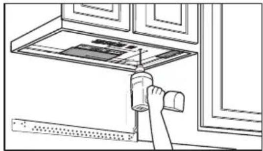
Using the top cabinet template
There are instructions on the top cabinet template that detail how it should be used.
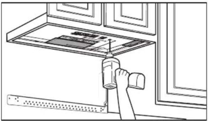
Tape the top cabinet template to the under side of the cabinet where the microwave will be installed.
Drill holes for the top support screws, a hole large enough for the power cord to fit through and a cutout large enough for the exhaust adapter.
natural_image
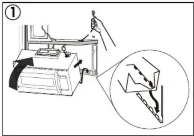
Line drawing of a hand using a tool to clean or install a window (no text or symbols visible)Check for proper damper operation
Place the microwave in its upright position with the top of the appliance facing up.
Make sure the tape securing the damper is removed and the damper pivots easily before mounting the microwave.
Attach the exhaust adapter to the blower plate by sliding it into the guides. Secure the adapter with one sheet metal screw.
natural_image
Technical line drawing of a battery casing with internal components and mounting bracket (no text or symbols)INSTALLATION INSTRUCTIONS
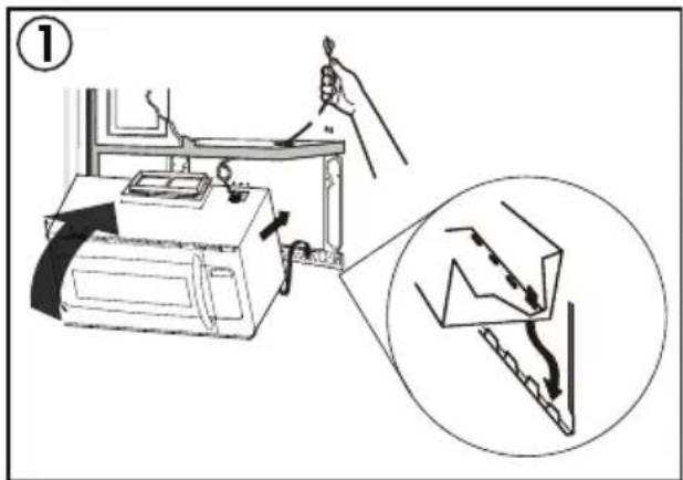
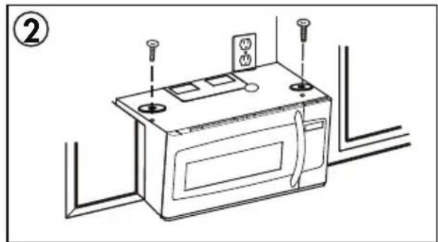
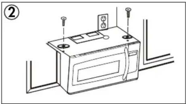
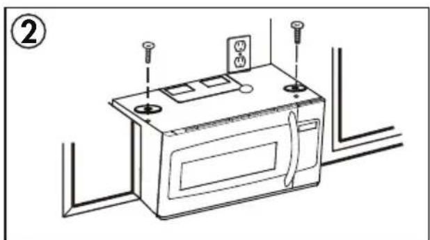
Mounting the microwave oven
For easier installation and personal safety, two people should be used to install the microwave.
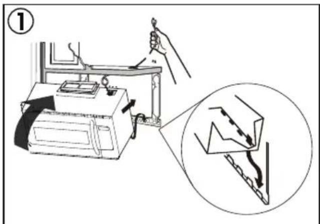
Do not grip or use the handle during installation.
If the surrounding cabinets are metal, use the nylon grommet around the power cord hole to prevent damage to the cord.
When mounting the microwave, thread the power cord through the hole in the cabinet. Keep the cord tight when mounting the microwave to ensure the cord does not get pinched. Do not lift the microwave by the cord.
-
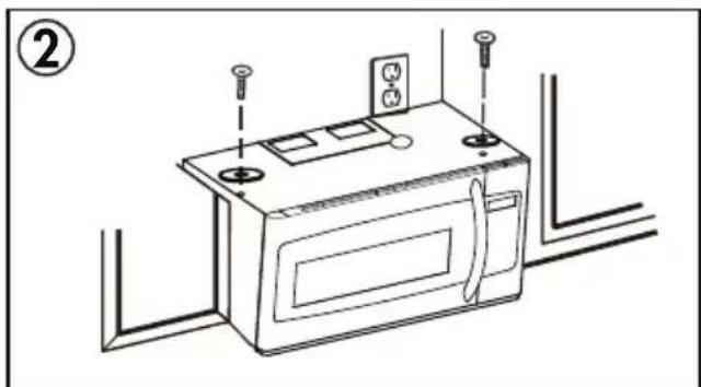
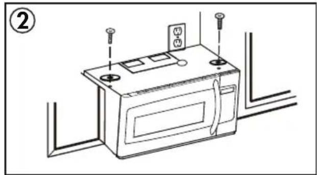
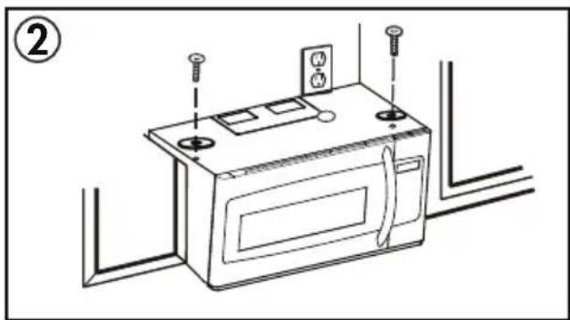
Lift the microwave, tilt it forward and hook the slots on the back of the microwave onto the lower tabs of the mounting plate. Rotate the front of the microwave against the bottom of the cabinet.
-
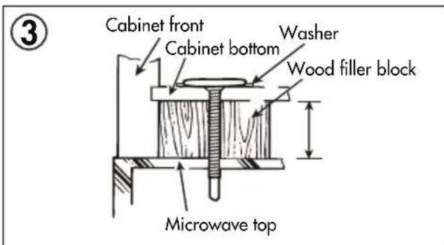
Insert two self aligning machine screws with washers through the top cabinet holes and tighten two turns.
-
If the cabinet has an overhang, insert the wood filler blocks before completely tightening the screws.
natural_image
Line drawing of a microwave oven with attached electrical outlets and screwdrivers (no text or symbols)
INSTALLATION INSTRUCTIONS
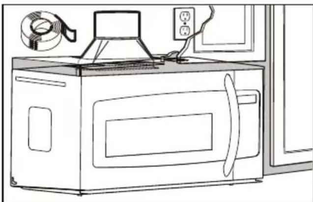
Install grease fi Iters
Slide the grease fi Iters into the openings in the bottom of the microwave until they click into place. The appliance should not be operated without the grease fi Iters installed.
Connecting ductwork
Adjust the exhaust adapter inside the cabinet so it can connect to the house duct.
Extend the house duct down to connect to the exhaust adapter.
Use duct tape to seal the exhaust duct joints.
natural_image
Line drawing of a microwave oven with a rack-mounted fan and power outlet (no text or symbols)INSTALLATION INSTRUCTIONS
OUTSIDE BACK EXHAUST
Use these instructions if the appliance will be vented to the outside through the back of the appliance.
Cut a 12" x 4" square hole in the rear wall for the outside exhaust. Follow the instructions included on the rear template.
Install the mounting plate
Use a 5/8" drill to make two holes that will enter the drywall. Use a 3/16" drill to make a hole that will enter a wall stud. Use the mounting template to decide the location of the holes. At least one hole must enter a wall stud.
Insert the machine screws into the mounting plate through the holes designed to go into drywall and attach the wing nuts 3/4" onto each machine screw.
Place the mounting plate against the wall and insert the wing nuts into the holes in the wall. The wing nuts will open on the other side of the wall to secure the screw.
Do not place a wing nut on the screw that will go into the wall stud. Insert a wood screw through the mounting plate and into the wall stud. Tighten all screws.
INSTALLATION INSTRUCTIONS
Using the top cabinet template
There are instructions on the top cabinet template that detail how it should be used.
Tape the top cabinet template to the under side of the cabinet where the microwave will be installed.
Drill holes for the top support screws and a hole large enough for the power cord to fit through.
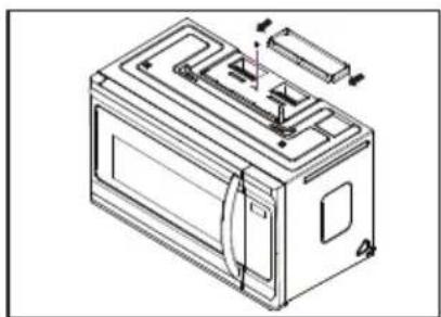
Adapting blower for back exhaust
- Remove the screws that secure the blower motor. Lift up the blower plate.
- Remove part A with tin snips or scissors.
- Pull out the blower unit. Be careful not to stretch the wires and make sure the wires do not get pinched. Rotate the blower so that it faces toward the back and replace it in the appliance. The blower unit exhaust openings should match the exhaust openings on the rear of the microwave.
- Close the blower plate. Attach the exhaust adapter to the back of the microwave by sliding it into the guides at the top. Push in securely until the screw holes are visible. Ensure that the damper hinge is installed so that it is at the top and the damper swings freely.
- Secure the blower motor with screws. Secure the blower plate with screws.

natural_image
Line drawing of a hand using a tool to clean or install a wall-mounted device (no text or symbols visible)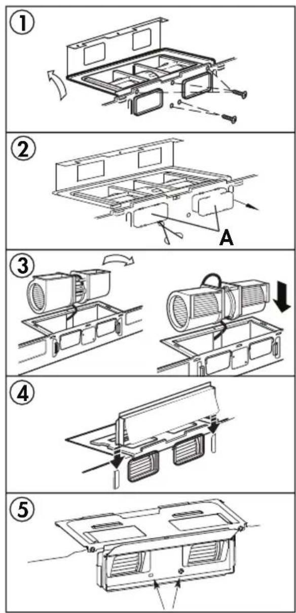
INSTALLATION INSTRUCTIONS
Mounting the microwave oven
For easier installation and personal safety, two people should be used to install the microwave.
Do not grip or use the handle during installation.
If the surrounding cabinets are metal, use the nylon grommet around the power cord hole to prevent damage to the cord.
When mounting the microwave, thread the power cord through the hole in the cabinet. Keep the cord tight when mounting the microwave to ensure the cord does not get pinched. Do not lift the microwave by the cord.
- Lift the microwave, tilt it forward and hook the slots on the back of the microwave onto the lower tabs of the mounting plate. Rotate the front of the microwave against the bottom of the cabinet.
- Insert two self aligning machine screws with washers through the top cabinet holes and tighten two turns.
- If the cabinet has an overhang, insert the wood filler blocks before completely tightening the screws.
natural_image
Line drawing of a microwave oven with screwdrivers and mounting holes (no text or symbols)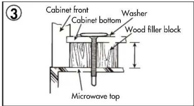
Install grease fi Iters
Slide the grease fi lters into the openings in the bottom of the microwave until they click into place. The appliance should not be operated without the grease fi lters installed.
Connecting ductwork
Adjust the exhaust adapter so it can connect to the house duct.
Extend the house duct to connect to the exhaust adapter.
Use duct tape to seal the exhaust duct joints.
INSTALLATION INSTRUCTIONS
RECIRCULATING (NON-VENTED)
Use these instructions if the appliance will not be vented to the outside.
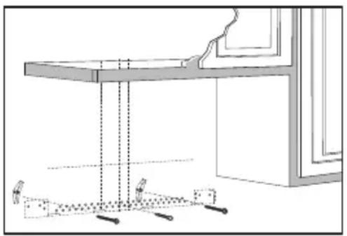
Install the mounting plate
Use a 5/8" drill to make two holes that will enter the drywall. Use a 3/16" drill to make a hole that will enter a wall stud. Use the mounting template to decide the location of the holes. At least one hole must enter a wall stud.
Insert the machine screws into the mounting plate through the holes designed to go into drywall and attach the wing nuts 3/4" onto each machine screw.
Place the mounting plate against the wall and insert the wing nuts into the holes in the wall. The wing nuts will open on the other side of the wall to secure the screw.
Do not place a wing nut on the screw that will go into the wall stud. Insert a wood screw through the mounting plate and into the wall stud. Tighten all screws.
natural_image
Technical line drawing of a table with supports and a window frame (no text or symbols)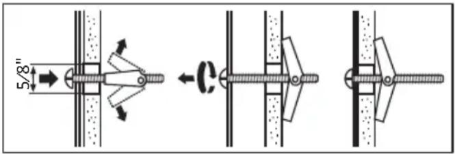
INSTALLATION INSTRUCTIONS
Using the top cabinet template
There are instructions on the top cabinet template that detail how it should be used.
Tape the top cabinet template to the under side of the cabinet where the microwave will be installed.
Drill holes for the top support screws and a hole large enough for the power cord to fit through.
Adapting blower for recirculating exhaust
-
Remove the screws that secure the blower motor. Lift up the blower plate.
-
Pull out the blower unit. Be careful not to stretch the wires and make sure the wires do not get pinched. Rotate the blower so that it faces toward the front and replace it in the appliance.
-
Secure the blower motor with screws. Secure the blower plate with screws.
natural_image
Line drawing of a hand using a tool to clean or install a ceiling-mounted device (no text or symbols visible)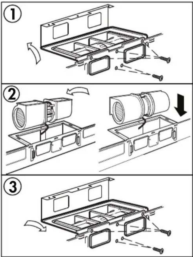
INSTALLATION INSTRUCTIONS
Mounting the microwave oven
For easier installation and personal safety, two people should be used to install the microwave.
Do not grip or use the handle during installation.
If the surrounding cabinets are metal, use the nylon grommet around the power cord hole to prevent damage to the cord.
When mounting the microwave, thread the power cord through the hole in the cabinet. Keep the cord tight when mounting the microwave to ensure the cord does not get pinched. Do not lift the microwave by the cord.
-
Lift the microwave, tilt it forward and hook the slots on the back of the microwave onto the lower tabs of the mounting plate. Rotate the front of the microwave against the bottom of the cabinet.
-
Insert two self aligning machine screws with washers through the top cabinet holes and tighten two turns.
-
If the cabinet has an overhang, insert the wood filler blocks before completely tightening the screws.
natural_image
Line drawing of a microwave oven with mounting holes and electrical outlets (no text or symbols)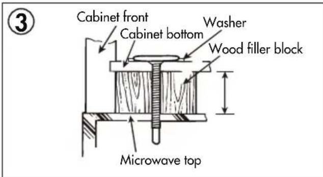
INSTALLATION INSTRUCTIONS
Install grease filters
Slide the grease fi Iters into the openings in the bottom of the microwave until they click into place. The appliance should not be operated without the grease fi Iters installed.
Air recirculation
There is no duct work required for this type of installation. Air from the appliance will exhaust through the front vent and recirculate into the air in the room.
Charcoal fi Iter
The charcoal fi lter should be used in non-vented, recirculating installations. The fi lter should be changed every 6 to 12 months depending on use.
- Remove the two screws securing the louver on the front of the microwave.
- Remove the used charcoal filter.
- Install the new charcoal fi lter. The wire mesh of the fi lter should be visible from the front.
- Reinstall the louver.
COOKING UTENSILS GUIDE
RECOMMENDED
Microwave Browning Dish: Used to brown the exterior of small food items. Follow the directions provided with the browning dish.
Microwavable Plastic Wrap: Used to retain steam. Leave a small opening to avoid a build up of steam. Do not place directly on food.
Glass and Ceramic Bowls and Dishes: Use for heating or cooking.
Paper Plates and Cups: Use for short term heating at low temperatures. Do not use recycled paper as they can contain metal and could ignite.
Paper Towels and Napkins: Use for short term heating and covering. Do not use recycled paper towels as they can contain metal and could ignite.
Wax Paper: Use as a cover to prevent splattering.
Thermometers: Only use those that are labeled "microwave safe" and follow all directions.
Note: To check if a dish is safe for use in the microwave, place the empty dish in the appliance and microwave on high for 30 seconds. If the dish becomes very hot, it should not be used.
LIMITED USE
Aluminum Foil: Using too much foil can cause arcing and damage the appliance. Keep a distance of at least 1 inch (2.6 cm) between the foil and the inside of the appliance.
Ceramic, Porcelain, Plastic and Stoneware: Only use if they are labeled "microwave safe".
NOT RECOMMENDED
Glass Jars and Bottles: Regular glass is too thin to be used in a microwave. It can shatter and cause damage or injury.
Paper Bags: These are a fire hazard and could ignite. The only exception is popcorn bags, which are designed for microwave use.
Styrofoam Plates and Cups: These can melt and leave an unhealthy residue on food.
Plastic Storage and Food Containers: These can melt and ignite.
Metal Utensils: These can cause arcing and damage to the appliance. Remove all metal before operation.
COOKING TECHNIQUES
To achieve the best results when cooking in this appliance, follow the suggestions below.
STIRRING
Stir foods while cooking to distribute heat evenly. Food at the outside of the dish absorbs more energy and will heat more quickly so stir from the outside of the dish toward the center.
ARRANGEMENT
Arrange unevenly shaped foods thicker, meatier parts toward the outside of the turntable so they receive more heat. To prevent overcooking, place delicate items toward the center of the turntable.
SHIELDING
Delicate foods can be shielded with narrow strips of aluminum foil to prevent overcooking. Use only small amounts of foil as this can cause arcing and damage to the appliance.
TURNING
Turn food over midway through cooking to expose all parts to the microwave energy. This is important with large items and meat.
STANDING
Foods cooked in a microwave build up internal heat and continue to cook for a few minutes after heating stops. Let foods stand to complete cooking, especially meats and liquids. All liquids should be allowed to stand for a few minutes after cooking and should be shaken or stirred before consuming.
ADDING MOISTURE
Microwave energy is attracted to water molecules. Food that is uneven in moisture content should be covered and allowed to stand after cooking to allow the heat to disperse evenly. Add a small amount of water to dry food to help it cook.
OPERATING INSTRUCTIONS
FIRST TIME USE
When the appliance is plugged in for the first time, the display will show "12:00". Use the number pad to enter the current time and then press the clock button to confirm
When setting the cook timer, the appliance will return to standby mode if there is no input within 1 minute.
During operation:
- Press the Start/+30SEC button to begin operation.
- Press the Stop button to cancel the cooking program.
- The appliance will beep four times at the end of a cooking program.
SETTING THE CLOCK
The clock can be set as a 12 hour or a 24 hour clock. Press the Clock button once to choose a 12 hour clock. Press the Clock button twice to choose a 24 hour clock.
To set the current time:
- Press the Clock button once or twice.
- Use the number pad to enter the current time.
- Press the Start/+30SEC button to confirm.
During operation, press the Clock button to see the current time.
MICROWAVE COOKING
- Press the Time Cook button. The display will show "00:00".
- Use the number pad to enter the desired cooking time. The maximum time is 99 minutes and 99 seconds.
- Press the Power level button to choose a power level. The default power level is 100%. The display will show "PL10". Use the number pad to enter the desired power level if 100% is not required.
- Press the Start/+30SEC button to begin operation.
Note: If "PLO" is selected, the appliance fan will run with no cooking function. This power level can be used to remove odors from the oven.
| Number Pad | Cooking Power | Display |
| 0 0% | PL-0 | |
| 1 10% | PL-1 | |
| 2 20% | PL-2 | |
| 3 30% | PL-3 | |
| 4 40% | PL-4 | |
| 5 50% | PL-5 | |
| 6 60% | PL-6 | |
| 7 70% | PL-7 | |
| 8 80% | PL-8 | |
| 9 90% | PL-9 | |
| 10 100% | PL10 |
OPERATING INSTRUCTIONS
Two Stage Cooking
Some recipes require different stages of cooking at different temperatures. To set a two stage cook program:
- Press the Time Cook button and use the number pad to enter the desired cooking time for the first stage.
- Press the Power level button and use the number pad to enter the desired power level for the first stage.
- Press the Time Cook button and use the number pad to enter the desired cooking time for the second stage.
- Press the Power level button and use the number pad to enter the desired power level for the second stage.
- Press the Start/+30sec button to begin operation.
LIGHT CONTROL
Press the Light button to control the light at the bottom of the microwave.
FAN CONTROL
The fan in the microwave can be used as a range hood to remove smoke, odors and grease from the air while cooking. Press the Fan button to control the fan speed.
- Press once for low speed.
- Press twice for high speed.
- Press three times to turn the tan off.
OPERATING INSTRUCTIONS - SENSOR COOK
The sensor cook buttons can be used to set automatic cooking functions for the below food types. The sensor settings will adjust cooking time based on how much humidity is released during cooking.
PIZZA
The pizza setting can be used to cook one or two slices of pizza. The weight range is 5-16 oz. and the maximum cooking time is 3 minutes and 45 seconds.
POTATO
The potato setting will automatically cook 1-3 potatoes (6-8 oz.) for a maximum of 15 minutes and 45 seconds.
MEAT
This setting can cook meat. The weight range is 5-24 oz. The maximum cook time is 10 minutes 45 seconds. Press 1 for pork, press 2 for chops, press 3 for ground meat, press 4 for chicken.
REHEAT
The reheat setting will warm precooked food. The weight range is 5-24 oz. and the maximum cook time is 8 minutes 45 seconds. Press 1 for a dinner plate, press 2 for casserole, press 3 for pasta.
POPCORN
The popcorn setting will automatically cook a 3.5 oz. bag of popcorn.
BEVERAGE
Beverages heated with the beverage setting may be very hot. Remove beverages with care. The number of servings is 1-3 cups (200 ml/cup) and the maximum cook time is 3 minutes and 50 seconds.
VEGGIES
The veggie setting can cook fresh or frozen vegetables. Press 1 for fresh veggies and 2 for frozen veggies. The weight range is 5-24 oz.
The maximum cook time for fresh veggies is 10 minutes 45 seconds. The maximum cook time for frozen veggies is 15 minutes 45 seconds.
OPERATING INSTRUCTIONS
WEIGHT DEFROST
The defrosting time and power level are adjusted automatically once the weight is entered.
- Press the Weight Defrost button.
- Use the number pad to enter the weight of the food that will be defrosted. Weight must be in ounces. Maximum weight is 96 ounces.
- Press the Start/+30SEC button to confirm.
During operation the appliance will pause and beep to indicate that the food should be turned over or stirred. Press the Start/+30SEC button to resume operation.
1LB DEFROST
This function allows fast defrosting of 1 lb of food.
During operation the appliance will pause and beep to indicate that the food should be turned over or stirred. Press the Start/+30SEC button to resume operation.
TIME DEFROST
The time defrost function will defrost food based on the time entered.
- Press the Time Defrost button. The display will show "DEF".
- Use the number pad to enter the desired defrosting time. The maximum time is 99 minutes and 99 seconds.
- Press the Start/+30SEC button to confirm.
During defrost the appliance will pause and beep. During this pause the food should be stirred or turned over to ensure even defrosting. Press the Start/+30SEC button to resume the program.
ADD 30 SECONDS FUNCTION
When the appliance is not in operation, pressing the +30SEC button will run the appliance for 30 seconds at 100% power level. This button can be pressed multiple times, each press will add a further 30 seconds to the cooking time.
OPERATING INSTRUCTIONS
ECO MODE
The eco function will save power by operating the microwave at lower settings. Press the Eco button once to set eco mode. The display and fan will turn off. Press any button to wake the appliance and use as normal. After one minute with no input, the appliance will return to eco mode.
Press the Eco button again to exit eco mode.
SETTING THE CHILD LOCK
To set the child lock, while the unit is in standby mode, press and hold the Stop button for 3 seconds. The appliance will beep to indicate that the child lock is activated and the display will show LOCK. While locked, the appliance cannot be used.
To cancel the child lock, press and hold the Stop button for 3 seconds. The appliance will beep to indicate that the child lock has been deactivated.
TIMER FUNCTION
To set the timer function:
- Press, the Timer button.
- Use the number pad to enter the desired time to run the microwave. The maximum time is 99 minutes and 99 seconds.
- Press the Start/+30SEC button to begin operation.
Note: Programs cannot be set while the timer is running.
LIGHT REPLACEMENT
Unplug the appliance before replacing the light bulbs. Remove the screw on the light cover and then remove the cover to expose the light bulbs. Do not replace with light bulbs greater than 30 watts. Replace the light cover before plugging in the appliance.
Light cover may become hot. Do not touch the cover while the light is on.
GREASE FILTERS
The grease fi liters on the bottom of the appliance should be cleaned at least once a month depending on use. Never operate the appliance or fans without the grease fi liters in place.
Pull down on the tab on the front of the fi lter and pull forward to remove it from the appliance. Soak the fi lter in a sink or dish pan fi lled with hot water and mild detergent. Do not use ammonia or other alkali as they will discolour the fi lter. Agitate and scrub the fi lter to remove embedded dirt. Rinse thoroughly and shake dry. Replace the fi lter in the appliance.
OPERATING INSTRUCTIONS
CLEANING
Turn off and unplug the appliance before performing any cleaning.
The inside of the appliance should be cleaned with a warm, damp cloth and mild detergents. Do not allow food splatters to build up on the inside of the appliance as this can affect the efficiency of the microwave and if sufficiently dirty, can ignite and cause fire.
The outside of the appliance should be cleaned with a warm, damp cloth. To avoid damage to internal components, do not allow any water to drip into the ventilation openings.
Clean the door and window on both sides, the door seals and the adjacent parts frequently with a damp cloth to remove any spills or splatters. Do not use abrasive cleaners.
Do not allow the control panel to become wet. If necessary, clean the control panel with a damp cloth and then wipe dry.
The glass tray can be removed and cleaned in warm water and mild detergent or can be placed in a dishwasher.
The roller ring and oven floor should be cleaned regularly to avoid excessive noise or spilling. The roller ring can be cleaned in warm water and mild detergent or can be placed in a dishwasher. Ensure that the roller ring and glass tray are replaced in the proper position to avoid noise or spilling.
MAINTENANCE
To remove odors from the microwave:
- Combine a cup of water with the juice and skin of one lemon in a microwavable bowl.
- Microwave on full power for 5 minutes.
- Wipe the inside of the appliance and glass tray and roller ring thoroughly with a warm, damp cloth.
MICA SHEET
Inside the appliance there is a cardboard mica sheet protecting the magnetron. Do not remove this from the appliance as exposing the magnetron to food splatters can cause arcing or fire. If it becomes dirty, the mica sheet can be cleaned with a warm cloth.
DISPOSAL
This product should not be treated as ordinary household waste, it should be transported to the appropriate collection point for the recycling of electrical components. For information on local waste collection points, contact your local waste disposal agency or government office.
LIMITED "IN HOME" WARRANTY
This quality product is warranted to be free from manufacturer's defects in material and workmanship, provided that the unit is used under the normal operating conditions intended by the manufacturer. This warranty is available only to the person to whom the unit was originally sold by Danby Products Limited (Canada) or Danby Products Inc. (U.S.A.) (hereafter "Danby") or by an authorized distributor of Danby, and is non-transferable.
TERMS OF WARRANTY
Plastic parts are warranted for thirty (30) days from the date of purchase, with no extensions provided.
First 18 months: During the first eighteen (18) months, any functional parts of this product found to be defective, will be repaired or replaced, at warranter's option, at no charge to the original purchaser.
To obtain service: Contact the dealer where the unit was purchased, or contact the nearest authorized Danby service depot, where service must be performed by a qualified service technician. If service is performed on the unit by anyone other than an authorized service depot, all obligations of Danby under this warranty shall be void.
Boundaries of In Home service: Danby reserves the right to limit the boundaries of "In Home Service" to the proximity of an authorized service depot. Any appliance requiring service outside the limited boundaries of "In Home Service", will be the consumers responsibility to transport at their own expense to the original point of purchase or a service depot for repair. If the appliance is installed in a location that is 100 kilometers (62 miles) or more from the nearest service center, it must be delivered to the nearest authorized Danby Service Depot by the purchaser.
Nothing within this warranty shall imply that Danby will be responsible or liable for any spoilage or damage to food or other contents of this appliance, whether due to any defect of the appliance, or its use, whether proper or improper.
EXCLUSIONS
Save as herein provided, by Danby, there are no other warranties, conditions, representations or guarantees, express or implied, made or intended by Danby or its authorized distributors and all other warranties, conditions, representations or guarantees, including any warranties, conditions, representations or guarantees under any Sale of Goods Act or like legislation or statute is hereby expressly excluded. Save as herein provided, Danby shall not be responsible for any damages to persons or property, including the unit itself, howsoever caused or any consequential damages arising from the malfunction of the unit and by the purchase of the unit, the purchaser does hereby agree to indemnify and hold harmless Danby from any claim for damages to persons or property caused by the unit.
GENERAL PROVISIONS
No warranty or insurance herein contained or set out shall apply when damage or repair is caused by any of the following:
1) Power failure.
2) Damage in transit or when moving the appliance.
3) Improper power supply such as low voltage, defective house wiring or inadequate fuses.
4) Accident, alteration, abuse or misuse of the appliance such as inadequate air circulation in the room or abnormal operating conditions (ie. extremely high or low room temperature).
5) Use for commercial or industrial purposes (ie. If the appliance is not installed in a domestic residence).
6) Fire, water damage, theft, war, riot, hostility, acts of God such as hurricanes, floods etc.
7) Service calls resulting in customer education.
8) Improper Installation (ie. Building-in of a free standing appliance or using an appliance outdoors that is not approved for outdoor application, including but not limited to: garages, patios, porches or anywhere that is not properly insulated or climate controlled).
Proof of purchase date will be required for warranty claims; retain bills of sale. In the event that warranty service is required, present the proof of purchase to our authorized service depot.
INTERFÉRENCE AUX FRÉQUENCES RADIO ÉLECTRIQUES
GARDER CES INSTRUCTIONS!
INSTRUCTIONS DE MISE À LA TERRE
natural_image
Pure technical line drawing of a mechanical part or housing without any text, numbers, or symbols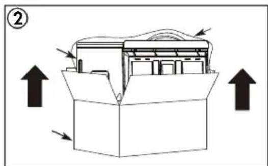
natural_image
Technical line drawing of a mechanical housing with internal components and directional arrows (no text or symbols)natural_image
Illustration of a hand holding a pen, pointing at a window with dashed lines and arrows indicating direction (no text or symbols)INSTRUCTIONS D'INSTALLATION
UTILISATION DU MODÈLE D'INSTALLATION
INSTRUCTIONS D'INSTALLATION
INSTRUCTIONS D'INSTALLATION
ECHAPPEMENT DE CAPOT
natural_image
Line drawing of a hand using a tool to lift a window (no text or symbols)natural_image
Technical line drawing of a microwave oven with internal components and mounting bracket (no text or symbols)INSTRUCTIONS D'INSTALLATION
natural_image
Line drawing of a microwave oven with screwdrivers and electrical outlets (no text or symbols)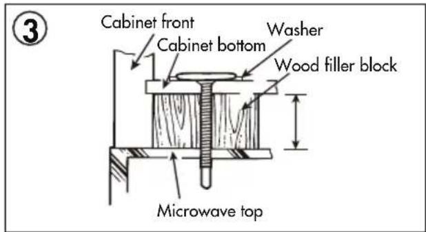
INSTRUCTIONS D'INSTALLATION
natural_image
Line drawing of a microwave oven with a coiled hose and control panel (no text or symbols)INSTRUCTIONS D'INSTALLATION
ECHAPPEMENT EXTERIEUR ARRIERE
INSTRUCTIONS D'INSTALLATION
natural_image
Line drawing of a hand using a tool to clean or install a window with a rack (no text or symbols)INSTRUCTIONS D'INSTALLATION
natural_image
Line drawing of a microwave oven with mounting holes and electrical outlets (no text or symbols)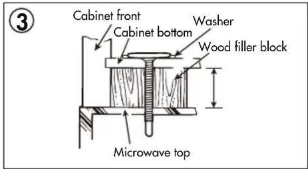
natural_image
Line drawing of a hand using a tool to clean or install a window (no text or symbols visible)INSTRUCTIONS D'INSTALLATION
natural_image
Line drawing of a microwave oven with screw bolts and a wall-mounted door (no text or symbols)