
Interact Solution - Air Conditioning DOMETIC - Free user manual and instructions
Find the device manual for free Interact Solution DOMETIC in PDF.
| Product type | Central control and monitoring system for recreational vehicle |
| Brand | Dometic |
| Model | Interact Solution |
| Display | 3.5-inch (89 mm) color touch screen |
| Power supply | 12 V DC (via RV electrical system) |
| Connectivity | Wi-Fi (LR-125 module), RV-C bus |
| Main functions | Control of climate, lighting, awnings, tanks, power (inverter, generator, battery), alarms, and programs |
| Mobile app | Compatible with iOS and Android (System Control app) |
| Proximity sensor | Yes, adjustable (sensitivity from 1 to 10) |
| Operating temperature | -20 °C to 60 °C (-4 °F to 140 °F) |
| Maintenance and cleaning | Clean with a soft, dry cloth; avoid abrasive products |
| Safety | Safety instructions to avoid fire, electric shock, or explosion; use only approved Dometic parts |
| Spare parts and repairability | Contact Dometic customer service at 1-800-544-4881 or by email |
| Warranty | Limited one-year warranty (see www.dometic.com/warranty) |
| Dimensions (approx.) | Approximately 89 mm (screen width) |
| Weight (approx.) | Not specified, estimated < 0.5 kg |
Frequently Asked Questions - Interact Solution DOMETIC
User questions about Interact Solution DOMETIC
0 question about this device. Answer the ones you know or ask your own.
Ask a new question about this device
Download the instructions for your Air Conditioning in PDF format for free! Find your manual Interact Solution - DOMETIC and take your electronic device back in hand. On this page are published all the documents necessary for the use of your device. Interact Solution by DOMETIC.
USER MANUAL Interact Solution DOMETIC
Cancer and Reproductive Harm
www.P65Warnings.ca.gov
Service Center & Dealer Locations
Visit: www.dometic.com
Read these instructions carefully. These instructions MUST stay with this product.
Contents
1 Explanation of Symbols and Safety Instructions 3
1.1 Recognize Safety Information ....3
1.2 Understand Signal Words ....3
1.3 Supplemental Directives .... 3
1.4 General Safety Messages ....3
2 General Information....3
2.1 Key Features .... 4
3 Intended Use....4
4 Operation ....4
4.1 Touch-Screen Navigation and Use .....5
4.1.1 Main Navigation Screen and Icons....5
4.1.2 Climate Screens....6
4.1.3 Mechanical Screen....7
4.1.4 Lights Screen 9
4.1.5 Power Screen .....10
4.1.6 AGS Screen .....13
4.1.7 Tanks Screen ..... 15
4.1.8 Alarms Screen .....15
4.1.9 Settings Screen ..... 19
4.1.10 Programs Screen 24
4.1.11 Fuses Screen 27
4.1.12 Bedroom Screen 27
4.1.13 Bathroom Screen 28
4.1.14 Entry Screen.... 28
4.1.15 Clock Screen 29
4.1.16 Notifications Screen 29
4.2 Mobile Application Navigation and Use.....30
4.2.1 Prerequisites 30
4.2.2 Initial Connection.... 30
4.2.3 Password Settings....31
4.2.4 Navigation and Use 32
5 Maintenance.... 34
5.1 Care and Cleaning 34
5.2 Preventive Maintenance.... 34
6 Troubleshooting.... 34
7 Disposal 35
LIMITED ONE-YEAR WARRANTY.... 35
1 Explanation of Symbols and Safety Instructions
This manual has safety information and instructions to help you eliminate or reduce the risk of accidents and injuries.
1.1 Recognize Safety Information

This is the safety alert symbol.
It is used to alert you to potential physical injury hazards. Obey all safety messages that follow this symbol to avoid possible injury or death.
1.2 Understand Signal Words
A safety symbol and/or signal word identify safety messages and indicate the hazard severity.

DANGER!
Indicates a hazardous situation that, if not avoided, will result in death or serious injury.

WARNING:
Indicates a hazardous situation that, if not avoided, could result in death or serious injury.

CAUTION:
Indicates a hazardous situation that, if not avoided, could result in minor or moderate injury.
NOTICE: Used to address practices not related to physical injury.

Indicates additional information that is not related to physical injury.
1.3 Supplemental Directives
To reduce the risk of accidents and injuries, please observe the following directives before proceeding to operate this appliance:
- Read and follow all safety information and instructions.
- Read and understand these instructions before operating this product.
- The installation must comply with all applicable local or national codes, including the latest edition of the following standards:
U.S.A.
- ANSI/NFPA70, National Electrical Code (NEC)
- ANSI/NFPA 1192, Recreational Vehicles Code
- ANSI Z21.57, Recreational Vehicles Code
Canada
– CSA C22.1, Parts I & II, Canadian Electrical Code
– CSA Z240 RV Series, Recreational Vehicles
1.4 General Safety Messages

WARNING: FIRE, IMPACT, AND/OR EXPLOSION HAZARD
Failure to obey the following warnings could result in death or serious injury:
- Use only Dometic replacement parts and components that are specifically approved for use with the appliance.
- Use care when diagnosing and/or adjusting components on a powered unit.
- Do not modify this product in any way. Modifications can be extremely hazardous.
- Do not allow children to play with this product or with fixed controls (if applicable).
2 General Information
Dometic Interact provides a central control and monitoring hub for the appliances in your recreational vehicle (RV). All of the LCDs in the RV communicate with each other continuously over the RV-C bus. When one LCD is down, the others can continue to operate.
Dometic Interact does not replace the actual hardware controllers for the systems within the coach; it is a display that sends the signals and commands to various components (such as load boxes) regarding the actions that should be taken.
The Dometic Interact system allows you to:
- Control the climate, lighting, awnings, slide-outs, water systems, door locks, and generators from convenient locations in and around your vehicle.
- Monitor the status of water tank levels, LP gas levels, and battery levels from any location.
- Predict the usage of onboard components. Predictive usage technology provides on-screen reporting of vital water and power resources, and determines when you should consider refilling or recharging.
2.1 Key Features
Dometic Interact has the following features and benefits when integrated with your RV:
- Convenient 3.5 in. (89 mm) touch-screen display
- Wireless network control and mobile application
- Single- or multiple-screen interfaces
- One-touch control for user-programmable modes, such as Home, Away, and Sleep
• Haptic touch and sound feedback - On-screen predictive usage
- Control and monitoring of your RV's vital and convenience features, such as:
-Lights
- Climate
- Generator
- Inverter
– Water holding tanks
- Water pump
-Awning
- Alarm clock
- Coach battery
3 Intended Use
Dometic Interact is intended to be used in conjunction with the existing control and/or monitoring devices within your RV. It creates a central hub that you can use to efficiently control and monitor your appliances, via the onboard touch-screen display or from your mobile application.
The manufacturer accepts no liability for damage in the following cases:
- Faulty assembly or connection
- Damage to the product resulting from mechanical influences and excess voltage
• Alterations to the product without express permission from the manufacturer - Use for purposes other than those described in the operating manual
Dometic Corporation reserves the right to modify appearances and specifications without notice.
4 Operation
WARNING: FIRE AND/OR IMPACT HAZARD.
Failure to obey the following warnings could result in death or serious injury:
- Avoid improper operation of the unit. Refer to the operating manuals for the specific products that this unit controls to understand and obey the applicable safety precautions.
- Do not allow anyone (including children) with reduced physical, sensory, or mental capabilities, or lack of experience and knowledge to use this product, unless they have been given supervision or instruction concerning the use of this product by a person responsible for their safety.
NOTICE: You can use multiple screens for different operations at the same time, but avoid performing a single operation from multiple screens.
Dometic Interact can be operated from the onboard touch-screen display, or via the mobile application (available for download on most mobile devices).
Refer to the following sections for more information about touch-screen and mobile application navigation and use, including information about:
- UI screens and buttons
• Control and monitoring functionality - Prerequisites (mobile only)
4.1 Touch-Screen Navigation and Use
This section describes how to use Dometic Interact from the touch-screen display.
Refer to Mobile Application Navigation and Use to learn how to operate the control using the mobile application.

The screens presented in this section vary according to the available appliances and the layout of your RV.
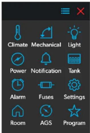
4.1.1 Main Navigation Screen and Icons
The Main Navigation screen is the default landing screen that you will use to navigate through the various areas of the control.
1 Main Navigation Screen
The Main Navigation screen provides access to the following screens:
- Climate
- Mechanical
-
Lights
-
Power
• AGS - Tanks
- Alarms
- Settings
- Programs
- Fuses
- Rooms
- Notifications
The following table describes the buttons that are used for general navigation of the various screens and to select settings.
Button Description
| Tap this icon to change the layout of the Main Navigation screen to list view. | |
| Tap this icon to change the layout of the Main Navigation screen to grid view. | |
| Tap this icon to close the current screen and return to the previous screen. | |
| Tap this icon to reach the Programs screen. | |
| Tap this icon to reach the Notifications screen. | |
| Tap this icon to return to the Main Navigation screen. | |
| Use toggle buttons to enable or disable functions. | |
| Use tumblers to select from a list of available options. Tumblers can be horizontal or vertical. Scroll to bring the desired setting to the middle position. | |
| Use sliders to increase or decrease the intensity of certain settings, such as light sources. Sliders can be horizontal or vertical. Slide the dot along the bar to the desired intensity. The indicator shows the intensity level as a percentage. |
EN
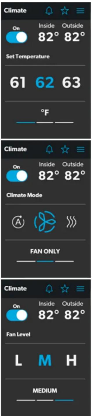
4.1.2 Climate Screens
The Climate screens allow you to control and monitor the climate within your RV, such as cooling, heating, and AC fans.
2 Climate Screens
4.1.2.1 Basic Air Conditioner Controls
From these screens, you can control or monitor the following basic air conditioner functions:
- Current Temperatures: These indicate the current indoor and outdoor air temperatures.
- Power: The default state for this button is off. Tap the toggle button once to turn climate control on. The applicable climate control appliance will be activated, depending on the set temperature and the temperature type currently selected.
- Set Temperature: This area displays a set of numbers ranging from 40–90 °F (4–32 °C), in ascending order. Use the tumbler to select your desired temperature setting.
- Climate Mode: Tap the center bar of the lower section indicator to view the climate mode settings. There are four climate mode options: Auto, Fan Only, Heat, and Cool.
Use the tumbler to select your desired mode:
- Choose Auto to allow the system to select the appropriate operating mode based on the configured settings and actual temperature readings.
- Choose Fan Only to turn off the AC or furnace and use only the fan for the AC unit.
- Choose Heat to turn on the furnace or heat pump.
- Choose Cool to turn on the AC unit.
Refer to the Settings Screen section for information about the Heat Mode settings.
The default setting for Heat Mode is Auto. When in this mode:
- If the outside temperature is above 40^ (4 °C), and the inside temperature is less than the Heat Set Point, then the heat pump will be on.
- If the difference between the inside temperature and the Heat Set Point is more than 5^ (-15 °C), the furnace will be on.
- If the outside temperature is below 40^ (4°C), the furnace will be on, even when the difference between the inside temperature and the Heat Set Point is less than 5^ (-15°C).
When Cool or Auto modes are chosen, a spinning icon will appear to indicate that the AC unit is initializing. This can take up to three minutes.
- Fan Level: Tap the right bar of the lower section indicator to view the fan speed settings for the AC unit. There are four fan speed options: low, medium, high, and auto.
Use the tumbler to select your desired fan speed:
- Choose L, M, or H to set the fan to the low, medium, or high setting.
– Choose A to set the fan to the Auto setting, where the unit will determine the appropriate fan speed automatically based on the set temperature and the actual temperature readings.
4.1.2.2 Advanced Climate Controls
The advanced climate controls include zones, mode, and scheduling:
- Zones: Use the tumbler to control the air flow required for the selected zone.
- Mode: Select the desired mode from the list of available modes such as Eco, Solar, or Boost.
- Scheduling: This allows you to set the climate schedule for air conditioning and/or heating as desired.
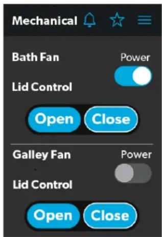
4.1.3 Mechanical Screen
The Mechanical screen allows you to control and monitor your mechanical appliances, such as awnings and ventilation fans.
4.1.3.1 Basic Vent Fan Controls
3 Mechanical Screen Basic Controls
The basic vent fan controls allow you to monitor the following functions:
- Power: The default state for the bath and galley fan Power buttons is off. Tap the Power button once to turn the fan on.

The lid must be open before the fan motor turns on. If the lid is closed when you attempt to turn the fan motor on, the lid will open automatically.
- Lid Control: The bath and galley fan lids are closed by default. Tap the Open or Close button for the galley or bath fan lid control to open or close the lids. A white outline around the button indicates the status of the lid.
4.1.3.2 Advanced Vent Fan Controls
The advanced vent fan controls include ventilation fan speed and rain sensor controls:
other
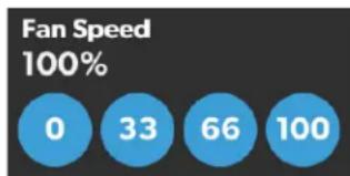
Fan Speed | Time (s) | Fan Speed (%) | | :--- | :--- | | 0 | 0 | | 33 | 33 | | 66 | 66 | | 100 | 100 |4 Mechanical Screen Fan Speed Controls
- Vent Fan Speed: The Fan Speed buttons control the speed of the galley vent fans. Tap a button to choose the desired vent fan speed from the four available options, which represent the percentages of the maximum fan speed: 0, 33, 66, or 100.
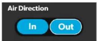
5 Mechanical Screen Air Direction Controls
• Air Direction: The Air Direction buttons control the direction of air flow from the vent fans. Tap the In button, and the vent fans will circulate fresh air into the RV from outside. Tap the Out button, and the fans will vent the inside air out of the RV (exhaust).
- Rain Sensor: When enabled, the Rain Sensor will close the fan lids automatically if moisture is detected in the air. After the Rain Sensor strip has dried and no moisture is detected in the air, the fan lids will automatically open (as long as the Open button is still enabled).
4.1.3.3 Awning Controls

6 Mechanical Screen Awning Controls
The awning controls allow you to extend or retract the awning.
When you attempt to extend or retract the awning using the awning controls, a pop-up alert message appears.
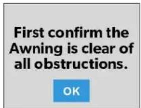
7 Awning Clear Message
After you have verified that the awning is clear of obstructions, tap the OK button.
There are two safety measures for awnings, which can vary depending on your specific configuration. Awnings will have no control when these measures are triggered:
- Parking Brake: In some configurations, the parking brake must be engaged prior to awning operation. If you attempt to extend or retract the awnings while the parking brake is not engaged, an alert appears.
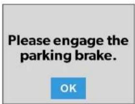
8 Parking Brake Alert
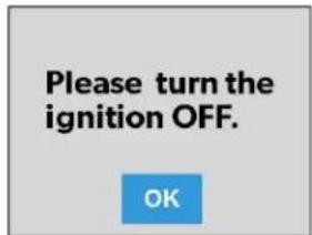
- Ignition: In other configurations, the RV ignition must be turned off prior to awning operation. If you attempt to extend or retract the awnings while the ignition is on, an alert appears.
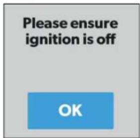
9 Ignition Safety Alert
There are two types of awning controls: momentary and automatic. The awning buttons function as follows:
- Momentary Awning Controls: Tap and hold the plus button (+) to extend the awning, or tap and hold the minus button (−) to retract the awning.
- Automatic Awning Controls: Tap the plus button (+) to extend the awning, or tap the minus button (−) to retract the awning. The awning will automatically reach full extension/retraction. If you want to stop the automatic extension/retraction process, tap the STOP button.
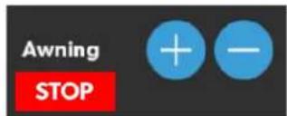
10 Mechanical Screen Automatic Awning Controls
4.1.3.4 Door Shade Controls
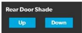
11 Door Shade Controls
The door shade controls allow you to control the shades on the RV doors.
Tap the Up button to roll the door shade down, and tap the Down button to roll the door shade up.
4.1.3.5 Furniture Controls
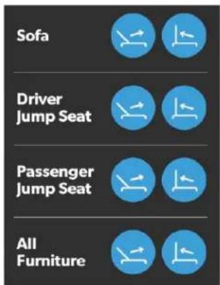
12 Furniture Controls
The furniture controls allow you to control the position of the furniture within your RV, such as sofas and jump seats.
Tap the appropriate button to recline or retract the selected furniture, as desired.
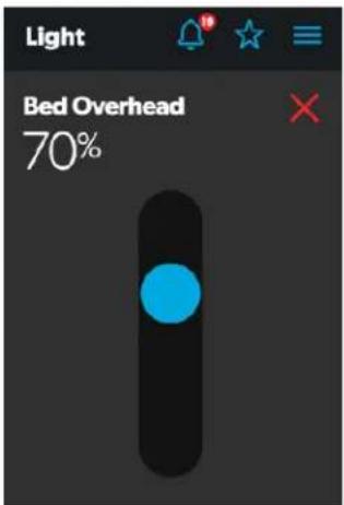
4.1.4 Lights Screen
The Lights screen allows you to control and monitor the various lighting sources throughout your RV, such as accent, galley, and utility lighting.
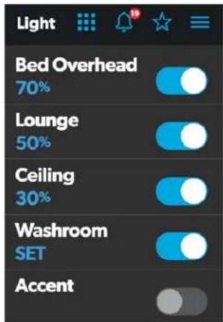
13 Lights Screen
These images show an example layout. Your Lights screen will vary according to the available lights and your RV layout.
From these screens, you can control and monitor the following functions:
- Basic Light Controls: The power buttons are used to turn a particular light or set of lights on and off. Tap the toggle or on/off buttons as desired to turn the lights on or off.
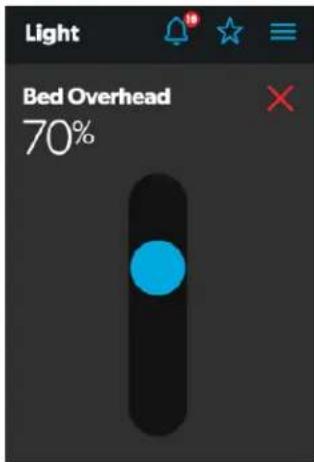
- Dimmer Controls: The light source intensity is indicated when the power to the light is activated. Tap the intensity indicator to open the vertical slider screen, where you can adjust the light source intensity.
- RGB Light Controls: Use the circular control to adjust the color of the lights as desired.
- RGB Dimmer Controls: Use the slider to adjust the brightness of the RGB light.
4.1.5 Power Screen
The Power screen allows you to monitor and control the available power sources for your RV, such as the battery, inverter, and generator.
4.1.5.1 Inverter Controls
From the Power screen, you can control and monitor the following inverter functions:
- Inverter Power: Use the toggle button to turn the inverter on or off. The Operating Mode indicator displays the operating mode of the inverter:
- Battery mode indicates that the inverter is running and supplying AC power to the loads from battery.
- Grid mode indicates that the inverter is charging the battery with AC voltage from shore power, but it's bypassing the inverter supply of AC power to the loads directly from the shore power.
- Off appears when the inverter is either off, or it is in an error, fault, or warning state.
If the inverter is in an error, fault, or warning state, the error code will be indicated on the inverter LCD screen.
- Load Wattage: This indicator displays the power consumed by the load from the inverter when in battery mode.
4.1.5.2 Battery Indicators
15 Battery Indicators
From the Power screen, you can monitor the following battery functions:
- Battery Voltage: This indicator provides voltage readings for the chassis (engine) and house (coach) batteries, respectively.
- Net Current Draw: This indicator shows the net current drawn during the discharge time and during the charging time.
14 Power Screen
- Battery Temperature: This indicator displays the current temperature of the battery.
- Battery Status: This indicator displays the current status of the battery, which can be either ON or OFF.
4.1.5.3 Charger Controls
From the Power screen, you can control and monitor the following charger functions:
- Charger Stage: This indicator shows the status of the onboard charger, as described in the following table:
| Number Status Description | ||
| 0 Disabled | The charger is disabled. | |
| 1 Not | Charging | The charger is enabled, but it is not charging (typically due to a lack of AC power). |
| 2 Bulk The charger is in the initial stage of the three-stage charging cycle. | ||
| 3 Absorption The charger is in the second stage of the three-stage charging cycle. | ||
| 4 Over | Charge | The charger is over-charging the batteries (this status is rare). |
| 5 Equalize | The charger is equalizing the batteries. | |
| 6 Float | The charger is in the third stage of the three-stage charging cycle. | |
| 7 Constant Voltage | The charger is providing constant voltage charging (typically used during single-stage charging cycles). | |
- Charger Current: This indicator shows the current that the charger is drawing from shore power.
- AC Input Current: This indicator shows the input current being drawn from shore power.
- AC Load Current: This indicator shows the current that the loads are drawing directly from shore power, bypassing the inverter.
- Solar Charger: The solar charger indicators provide the readings from the solar charger, such as voltage, amperage, amp-hours to battery, and power generated.
4.1.5.4 Generator Controls
From the Power screen, you can control and monitor the following generator functions:
- Generator: These options control both input and output, so you can monitor and control the onboard generator:
- The hours indicator shows the number of hours that the generator has run.
- The status indicator shows the state of the generator, as described in the following table:
| Number Status | Description | |
| 0 | Stopped | The generator is stopped. |
| 1 | Pre-Heat | The generator is preheat-ing. This is done prior to the cranking cycle. |
| 2 | Cranking | The generator is starting. |
| 3 | Running | The generator is running. |
| 4 | Priming | The generator is advanc-ing fuel. |
| 5 | Fault | There is a fault. |
| 6 | Engine Run Only | The generator is running, but not producing AC power. |
| 7 | Test Mode | This status is unused. |
| 8 | Voltage-Adjust-Mode | This status is unused. |
| 9 | Fault-Bypass-Mode | This status is unused. |
| 10 | Configuration-Mode | This status is unused. |
For a complete list of generator statuses, refer to the RV-C Specifications PDF.
- The START and STOP buttons control the output of the generator. Tap the START button to start the generator. The status changes to Cranking, and then to Running. A pop-up message should also appear.
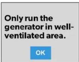
16 Ventilation Alert
- AGS: The Automatic Generator Start (AGS) indicator shows the status of the auto generator, which can be either ON or OFF.
There is also a CLEAR AGS button; when external activity is detected, tap this button to override the external activity demand and turn the AGS on.
External activity is a mechanism used to disable the AGS if the generator is manually stopped or started. This is a safety feature implemented so that if you manually stop the generator, the AGS system does not attempt to start it up again. External activity can also trigger on coach movement or ignition.
- DC Disconnect: Use the DC Disconnect toggle button to disconnect the coach battery. This prevents the battery from being used to power the onboard appliances.
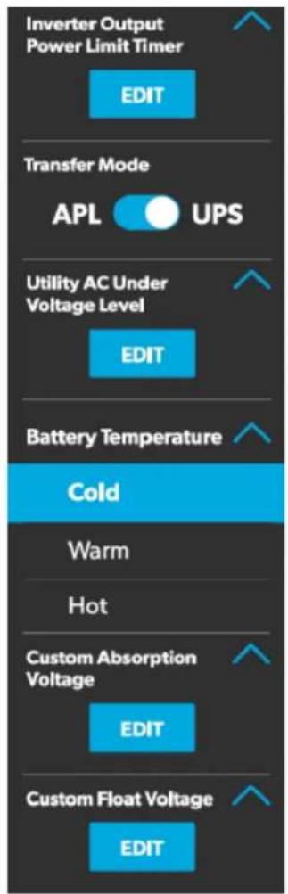
4.1.5.5 Advanced Inverter Settings
The Power screen also has a settings icon that you can tap to reach the Advanced Inverter Settings screen.

These inverter settings will be available for Xantrex Freedom SW 2000W inverters only.
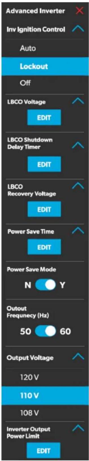
17 Advanced Inverter Settings Screens
The advanced inverter settings are for technicians only, and a pop-up message appears when you tap the advanced inverter icon.
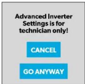
18 Advanced Inverter Settings Notification
Tap the CANCEL button to return to the Power screen, or tap the GO ANYWAY button to proceed to the Advanced Inverter screen.
There are some configurable settings available from the inverter LCD display.
From the Advanced Inverter Settings screen, technicians can control or monitor the following functions by tapping the expand/contract arrows, toggle buttons, EDIT, and OK buttons as applicable:
- Inverter Ignition Control
- LBCO Voltage
• LBCO Shutdown Delay Timer
• LBCO Recovery Voltage - Power Save Time
- Power Save Mode
- Output Voltage
• Inverter Output Power Limit
• Inverter Output Power Limit Timer - Transfer Mode
• Utility AC Under Voltage Level - Custom Absorption Voltage
- Custom Float Voltage
Complete the following steps to change the default value to a different value:
- Tap the expand/contract button for the feature setting that you want to update.
- Based on the available options for the selected feature, complete one of the following actions:
- Tap an option from the list.
- Tap the toggle button to activate/deactivate the feature.
-
Tap the EDIT button to view the available settings for the value.
-
If the EDIT button is selected:
a. Change the value as desired.
b. Tap the OK button to confirm the change and return to the Advanced Inverter Settings screen.
-
Repeat the previous steps to set the other feature settings as applicable.
-
After all updates are complete, tap the exit (x) icon to leave the feature settings mode and return to the Power screen.
4.1.6 AGS Screen
The AGS (Auto-Gen Start) screen allows you to monitor and control the automatic generator settings, such as the scheduled on/off times, scheduled run times, and voltages.
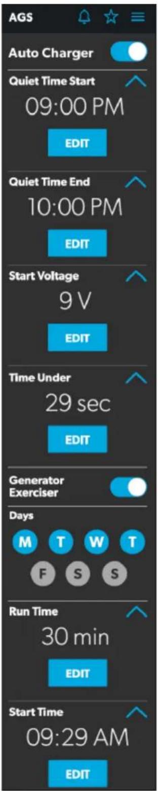
19 AGS Screen
From this screen, you can control and monitor the following functions:
- Auto Charger: Use this toggle button to enable or disable the auto charger. The auto charger is disabled by default. When you enable the auto charger, a pop-up message appears.
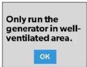
20 Ventilation Alert
The AGS becomes disabled if the ignition is turned on. If you attempt to enable the auto charger while the ignition is on, a pop-up message appears.
21 Ignition Alert
The following auto charger settings are available:
– Time Selection: Use the available tumblers (hour and minute) to set the desired quiet time start and end times. The generator is turned off automatically during the specified quiet time.
- Start Voltage: Use the tumbler to set your desired voltage setting (10 V–12.9 V). The default setting is 10.5 V. The Start Voltage tumbler controls the threshold voltage under which the AGS must turn on.
- Time Under: Use the tumbler to set your desired timer setting (0–10 min). The Time Under tumbler specifies the timer delay before the AGS starts, when the system drops below the set threshold voltage.
- AGS Climate: These options enable the climate controls, which run the air conditioner and heat pump of the generator when no shore power is available.
- Generator Exerciser: Use the toggle button to enable or disable the generator exerciser.
When you enable this setting, the Ventilation Alert pop-up message appears. The alert message does not appear when the generator activates based on the set schedule. The generator runs as scheduled if the ignition is turned off. If the ignition is turned on during a particular day that the generator is scheduled to run, it would skip running the generator that day unless the ignition is turned off.
The following generator exerciser settings are available:
– Days: Tap the desired days to specify the days on which the generator exerciser should run.
- Run Time: This tumbler controls the duration for the generator exerciser. Use the tumbler to set your desired time setting (10–2400 minutes).
- Start Time: These tumblers control the time at which the generator exerciser should start. Use the available tumblers (hour and minute) to set your desired time settings.
4.1.7 Tanks Screen
The Tanks screen allows you to monitor and control the holding tanks, such as the fresh, gray, and black water tanks.
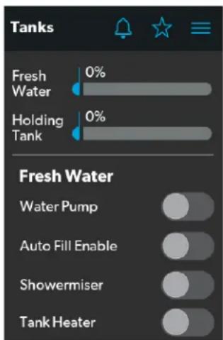
22 Tanks Screen
From this screen, you can monitor and control the following functions:
- Indicator Bars: The horizontal bars indicate the fluid levels for the various tanks (percent full), which are monitored continuously by the sensors attached to the outside of the tanks. These indicators are for monitoring purposes only and do not have any control functions.
- Water Pump: Use this toggle button to turn the water pump on or off. The water pump is deactivated by default.
- Auto Fill Enable: Use this toggle button to enable the auto fill feature. When enabled, the fresh water tank valve will open automatically to allow the tank to fill when it reaches a certain level.
The current status of the Auto Fill feature will be displayed, which can be ON, OFF, or FILLING.
- Showermiser: Use this toggle button to enable or disable the shower re-circulatory system.
- Tank Heater: Use this toggle button to enable or disable the tank heater.
The current status of the tank heater will be displayed, which can be ON or OFF.
4.1.8 Alarms Screen
The Alarms screen allows you to configure alarms for the system, including alert tones, alarm times, and alarm names.
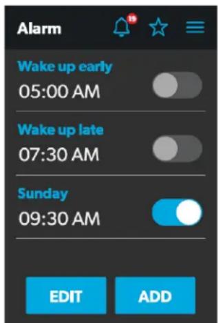
23 Alarms Screen
The Alarms screen is the main screen from which configured alarms can be monitored, enabled, or disabled. You can complete the following actions from this screen:
- Use the toggle button next to an alarm to enable or disable the alarm.
- Tap the alarm name to open the Alarm Edit window and edit a configured alarm.
- Tap the add button to open the Pop-Up Time window and create a new alarm.
When an active alarm triggers, a pop-up window appears on all displays in the coach along with the sound selected for the alarm.
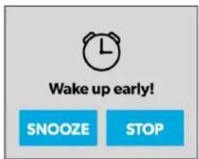
24 Alarm Notification
From any display, you can tap the SNOOZE button on the pop-up window to delay the alarm for five minutes, or tap the STOP button to stop the alarm.
The following sections provide more information about configuring new alarms and editing existing alarms.
4.1.8.1 Alarm Edit Window
The Alarm Edit window allows you to configure or alter the alarms listed on the Alarms screen.
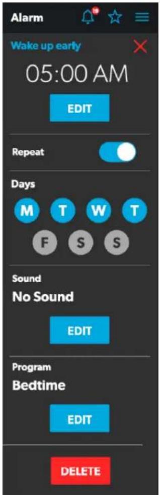
25 Alarm Edit Window
From this window, you can configure or adjust the following functions:
- Alarm Name: The name of the alarm displays. Tap the alarm name to open the Naming window.
- Time Selection: The set time for the alarm displays. Tap the EDIT button to open the Pop-Up Time window.
- Repeat: Use this toggle button to enable or disable a repeating alarm based on the days that you choose. When Repeat mode is enabled, it repeats the alarms for the days selected.
- Days: Tap the desired days (represented by single letters) to specify the days on which the alarm will repeat.
- Sound: The specified sound for the alarm displays. Tap the EDIT button to open the Sound Decision window.
- Program: The specified program for the alarm is displayed. Tap the EDIT button to open the Program Decision window.
- Delete: Tap this button to delete the alarm from the list of alarms displayed on the Alarms screen.
4.1.8.2 Pop-Up Time Window
The Pop-up Time window appears when you tap the Time Selection Edit button from the Alarm Edit window.
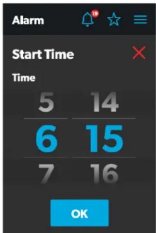
26 Pop-Up Time Window
From this window, you can use the available time tumblers (hour and minute) to set the time at which the alarm will trigger. Tap the OK button to save the time settings and return to the Alarm Edit window.
4.1.8.3 Sound Decision Window
The Sound Decision window appears when you tap the Sound Edit button from theAlarm Edit window. From this window, you can specify whether an alert tone should be applied to an alarm when it triggers.
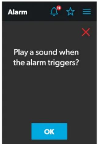
27 Sound Decision Window
Tap the OK button to confirm that a sound should be used when the alarm triggers, and the Sound Selection window opens.
4.1.8.4 Sound Selection Window
The Sound Selection window allows you to define an alert tone for an alarm when it triggers.
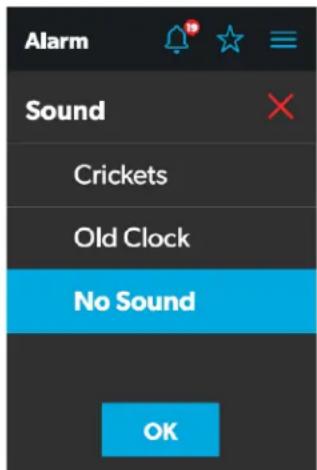
28 Sound Selection Window
Choose a sound for the alarm, and then tap the OK button to save your changes and return to the Alarm Edit window.
4.1.8.5 Program Decision Window
The Program Decision window appears when you tap the Program Edit button from the Alarm Edit window. From this window, you can determine whether a program should run when an alarm triggers.
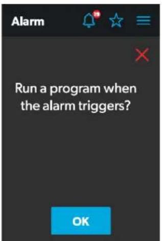
29 Program Decision Window
Tap the OK button to confirm that a program should run when the alarm triggers, and the Program Selection window opens.
4.1.8.6 Program Selection Window
The Program Selection window allows you to specify a program that will run when an alarm triggers.
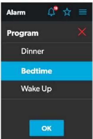
30 Program Selection Window
Choose a program for the alarm, and then tap the OK button to save your changes and return to the Alarm Edit window.
4.1.8.7 Naming Window
The Naming window appears when you tap the alarm name from the Alarm Edit window. From this window, you can specify a title for the alarm. The title of the alarm is what appears on the Alarms screen.
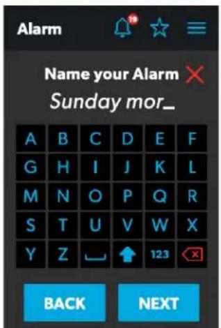
31 Naming Window
From this window, you can complete the actions that are described in the list that follows.
- Keypad: Use the keypad as desired to create a descriptive title for the alarm.
- Back: Tap this button to open the Program Decision window.
- Next: Tap this button to return to the Alarms screen.
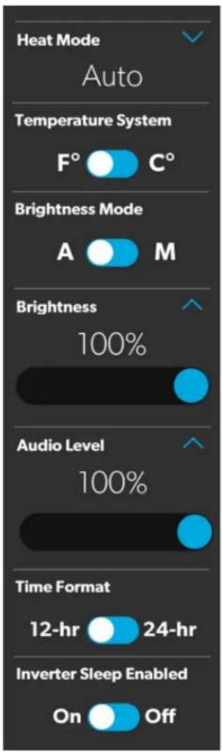
4.1.9 Settings Screen
The Settings screen allows you to control and configure the various aspects of the system and control, such as languages, screen brightness, and audio levels.
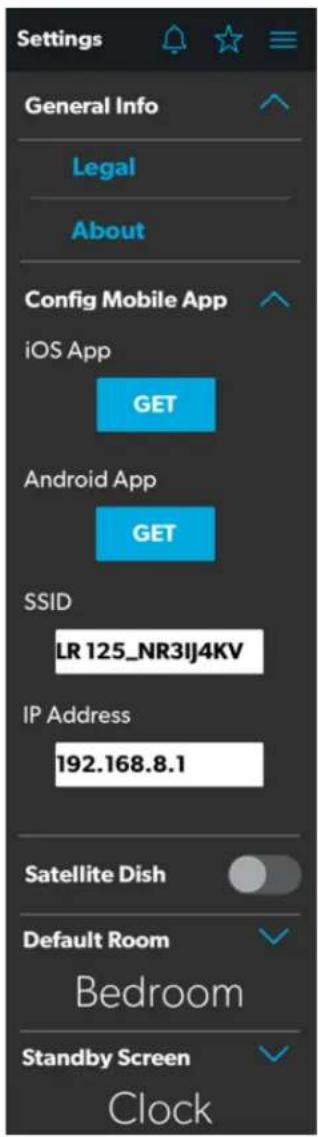
32 Settings Screen
Refer to the sections that follow for more information about the various sections of the Settings screen.
4.1.9.1 General Info Section
Use this section of the Settings screen to find general legal information and to learn about the system:
- Tap Legal to open the Legal window.
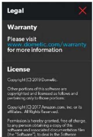
33 Legal Window
- Tap About to open the About window.
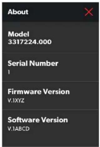
34 About Window
4.1.9.2 Config Mobile App Section
Use this section of the Settings screen to configure the mobile application connection settings from the touchscreen display.
Tap the iOS App GET button to open a window that contains a scannable QR code, which leads to the mobile application download from the App Store.

35 QR Code Window for iOS
Tap the Android App GET button to open a window that contains a scannable QR code, which leads to the mobile application download from the Google Play Store.

36 QR Code Window for Android
The available functions in this section of the Settings screen will vary based on the mode in which the installer has left the system: Public Access mode or Admin/User mode.
While in Public Access mode, you can view and monitor the following functions:
- SSID: This indicator displays the name of the network to which the system is connected.
- IP Address: This indicator displays the IP address to which the mobile application must be directed.
In Admin/User mode, you can monitor or configure the following functions:
- Wireless Mode: This indicator displays the currently selected mode. Tap the EDIT button to open the Wireless Mode window.
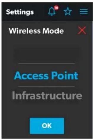
37 Wireless Mode Window
- Access Point: Choose this mode to configure the WiFi server module to become an access point, where personal mobile devices connect directly to it.
- Infrastructure: Choose this mode to configure the WiFi server module to connect through another WiFi device or modem.
- SSID: This indicator becomes and editable text field when in Admin/User mode. Tap the SSID text field to specify the SSID that must be entered when connecting to the system via the mobile application.
The SSID has a 63-character limit that when exceeded, prompts a pop-up message.
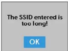
38 Character Limit Notification
- WiFi Password: Tap the WiFi Pwd text field to specify the password that must be entered when connecting to the system via the mobile application. When updating the password, three fields must be populated: Current Password, New Password, and Confirm New Password.
Entering the incorrect current password prompts a pop-up message.
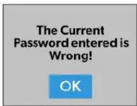
39 Password Incorrect Notification
The password has a 32-byte limit that when exceeded, prompts a pop-up message.
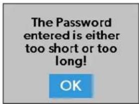
40 Password Limit Notification
4.1.9.3 Satellite Dish Option
Use the Satellite Dish toggle button to turn the satellite dish on or off.
This option may not be available from the Settings screen, as options vary per configuration.
4.1.9.4 Start Page Section
Use this section of the Settings screen to set the default screen that will display when you are within sensing range of the proximity sensor:
- Tap the EDIT button to open the Start Page window.
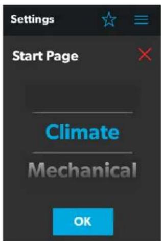
41 Start Page Window
- Use the tumbler to choose from a list of all available screens that you can set as your starting page.
- Tap the OK button to save your selection and return to the Settings screen.
4.1.9.5 Default Room Section
Use this section of the Settings screen to set the default room that appears on the Main Navigation screen:
- Tap the EDIT button to open the Default Room window.
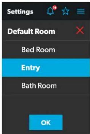
42 Default Room Window
- Choose from the list of available rooms (Bedroom, Entry, or Bathroom).
- Tap the OK button to save your selection and return to the Settings screen.
EN
4.1.9.6 Standby Screen Section
Use this section of the Settings screen to set the screen that should appear when you are outside of the sensing range of the proximity sensor:
- Tap the EDIT button to open the Standby Screen window.
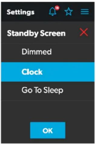
43 Standby Screen Window
-
Choose from the list of available display options:
-
Dimmed: The screen dims to 30% brightness until the proximity sensor senses movement.
- Clock: The screen displays the Clock screen until the proximity sensor senses movement. Refer to the Clock Screen section for more information.
-
Go To Sleep: The screen goes black until the proximity sensor senses movement.
-
Tap the OK button to save your selection and return to the Settings screen.
When you move into the sensing range of the proximity sensor, the display will show the start page that you selected.
4.1.9.7 Set Date & Time Section
Use this section of the Settings screen to set the current date and time:
- Tap Date to open the Date window.
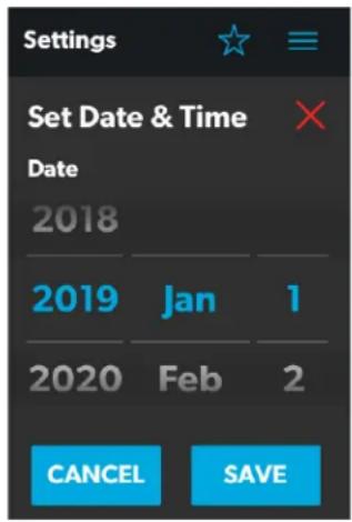
44 Date Window
- Use the day, month, and year tumblers to set the current date.
- Tap the SAVE button to save your selections and return to the Settings screen.
- Tap Time to open the Time window.
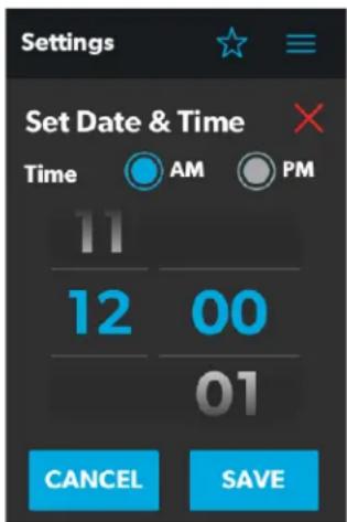
45 Time Window
- Use the AM/PM radio buttons and the hour and minute tumblers to set the current time.
The AM/PM radio buttons will not appear if the time format is set to 24-hour.
- Tap the SAVE button to save your selections and return to the Settings screen.
- Tap Time Zone to open the Time Zone window.
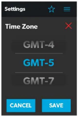
46 Time Zone Window
- Use the tumbler to select your time zone.
- Tap the SAVE button to save your changes and return to the Settings screen.
4.1.9.8 Heat Mode Section
Use this section of the Settings screen to set the method of heating:
- Tap the EDIT button to open the Heat Mode window.
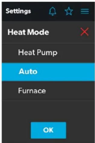
47 Heat Mode Window
- Choose from the list of available heat modes:
- Heat Pump: Only the heat pump runs when the coach requires heating.
EN
- Auto: The furnace and/or heat pump will run when the coach requires heating. The furnace will only turn on if the temperature drops below the set point. The furnace is used as a secondary boost for the heat pump if the temperature gets cold enough.
-
Furnace: Only the furnace runs when the coach requires heating.
-
Tap the OK button to save your selection and return to the Settings screen.
4.1.9.9 Temperature System Option
Use the Temperature System toggle button to set your desired temperature readings (in degrees Centigrade or Fahrenheit).
The side of the toggle button that holds the dot indicates the current selection.
4.1.9.10 Language Section
Use this section of the Settings screen to set the desired language for all screens on the control:
- Tap the EDIT button to open the Language window.
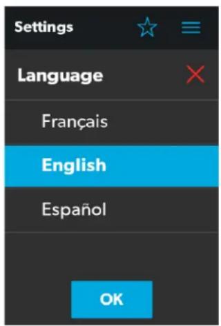
48 Language Window
-
Choose from the list of available languages (French, English, or Spanish).
-
Tap the OK button, and a pop-up message appears.
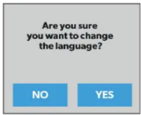
49 Language Change Confirmation
- Tap the YES button to save your selection and return to the Settings screen.
4.1.9.11 Brightness Mode Option
Use the Brightness Mode toggle button to choose between Auto (A) or Manual (M) adjustment modes:
- When the auto option is selected, the brightness is adjusted according to the ambient light sensor values.
- When the manual option is selected, you can adjust the screen brightness manually.
4.1.9.12 Screen Brightness Option
Use the Screen Brightness slider to manually set your desired screen brightness level (shown as a percentage of full intensity).
In order to set the screen brightness, the manual brightness mode must be selected.
4.1.9.13 Proximity Sensitivity Option
Use the Proximity Sensitivity slider to set your desired proximity sensor sensitivity level.
The number 1 represents the lowest sensitivity level, and 10 represents the highest sensitivity level.
4.1.9.14 Audio Level Option
Use the Audio Level slider to set your desired audio level intensity for the control (shown as a percentage of full intensity).
4.1.9.15 Time Format Option
Use the Time Format toggle button to set your desired time format (in 12-hour or 24-hour formats).
The side of the toggle button that holds the dot indicates the current selection.
4.1.9.16 Inverter Sleep Enable Option
Use the Inverter Sleep Enable toggle button to enable or disable this function.
- When this function is enabled, the system turns the inverter off upon restart (assuming the inverter is already on prior to power cycling).
- When this function is disabled, the inverter continues to run the loads from the battery after the power cycles.
4.1.10 Programs Screen
The Programs screen allows you to monitor, control, and configure the programs for the system.
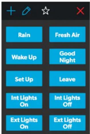
50 Programs Screen
The Programs screen is the main screen from which configured programs can be monitored, enabled, or disabled. You can complete the following actions from this screen:
- Tap the exit (x) icon to close the Programs screen and return to the previous screen.
-
Tap the plus (+) icon to open the New Programs window and create a new program.
-
Tap the pencil icon to open the Program Settings window.
- Tap any preexisting program button to start running the program, and a pop-up window appears to indicate that the program is running.

51 Running Program Notification
- Tap the STOP button to end the program.
Refer to the sections that follow for more information about configuring new programs and editing existing programs.
4.1.10.1 New Programs Window
The New Programs window allows you to configure a new program, which will be listed on the main Programs screen.
52 New Programs Window
From this window, you can configure or adjust the following functions:
- Locks: Use the available toggle buttons and check boxes in the Locks section to select the options that you want to control with the new program.
- Electrical: Use the available toggle buttons and check boxes in the Electrical section to select the options that you want to control with the new program.
- Back: Tap this button to cancel your changes and return to the main Programs screen.
- Next: Tap this button to save your changes and open the Naming Program window.
4.1.10.2 Program Settings Window
The Program Settings window allows you to select a program for editing or delete it.
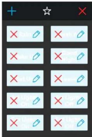
53 Program Settings Window
From this window, you can complete the following actions:
- Tap the pencil icon on a program to open the Edit Program window.
- Tap the exit (x) icon on the program to delete the program. A pop-up message appears.
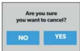
54 Running Program Notification
- Tap the No button to close the pop-up window without any changes.
- Tap the Yes button to cancel running the program and delete it from the system.
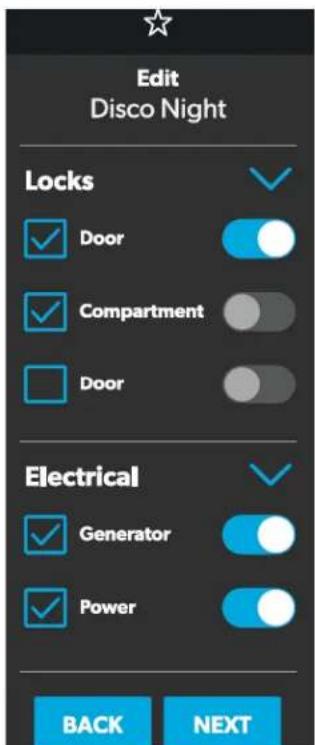
4.1.10.3 Edit Program Window
The Edit Program window allows you to configure or adjust the settings for your desired program.

55 Edit Program Window
From this window, you can configure or adjust the following functions:
- Locks: Use the available toggle buttons and check boxes in the Locks section to select the options that you want to control with the program.
- Electrical: Use the available toggle buttons and check boxes in the Electrical section to select the options that you want to control with the program.
- Back: Tap this button to cancel your changes and return to the main Programs screen.
- Next: Tap this button to save your changes and open the Naming Program window.
4.1.10.4 Naming Program Window
The Naming Program window allows you to configure or adjust the title of your desired program.
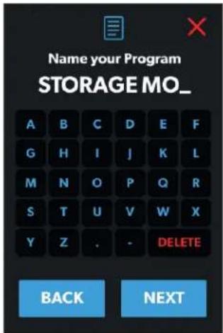
56 Naming Program Window
From this window, you can complete the following actions:
- Keypad: Use the keypad as desired to create a descriptive title for the program.
- Back: Tap this button to return to the Edit Program window.
- Next: Tap this button to open the Save Program window.
4.1.10.5 Save Program Window
The Save Program window allows you to confirm and save your program changes.
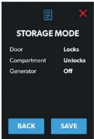
57 Save Program Window
From this window, you can complete the following actions:
- Back: Tap this button to return to the Naming Program window.
- Save: Tap this button save all updates to the program. Afterwards, the program will appear in the list of programs displayed on the main Programs screen.
4.1.11 Fuses Screen
The Fuses screen allows you to monitor and control the fuses for the various system components.

Fuses for the devices may vary for each system, based on the installed devices on the DC load box.
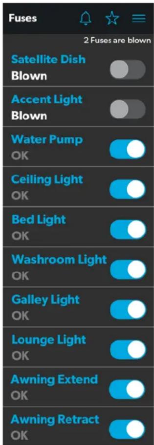
58 Fuses Screen
Each controlled component includes a toggle button indicating the fuse status: OK or blown.
EN
When the system detects a high inrush current or over-voltage condition, the software blows the fuse for that particular output.
Use the toggle button to reset a blown fuse, which sets it to the enabled (OK) state.
All of the blown fuses appear at the top of the list, followed by a list of active fuses.
When a fuse blows, the system produces a notification by showing a number beside the bell icon at the top of each screen. The system also plays a sound to notify you.
The number on the notification bell icon remains until you open the Notifications screen and close all notifications, one-by-one.
Refer to the Notifications Screen section for more information.
4.1.12 Bedroom Screen
The Bedroom screen allows you to monitor and control the available components within the bedroom area of your RV, such as the climate and lights.

Not all systems will include this screen. Control screens vary according to specific system configurations and available components.
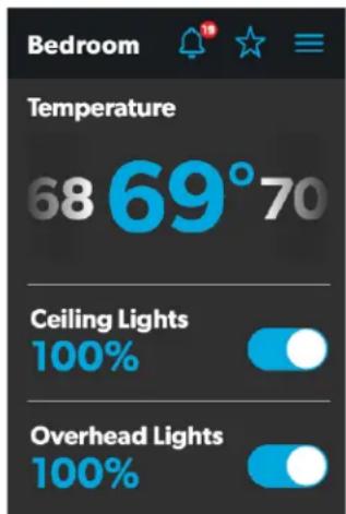
59 Bedroom Screen
From this screen, you can monitor and control the following functions:
- Temperature: Use the power toggle button to turn the climate controls on or off. When the power button is on, you can use the tumbler to select your desired temperature.
- Lights: Use the toggle button for the desired light source to turn it off or on. The light source brightness is indicated as a percentage of the maximum intensity. Tap the brightness indicator for the desired light to adjust the intensity via vertical slider.
4.1.13 Bathroom Screen
The Bathroom screen allows you to monitor and control the available components within the bathroom area of your RV, such as ventilation, water pump, and lights.

Not all systems will include this screen. Control screens vary according to specific system configurations and available components.
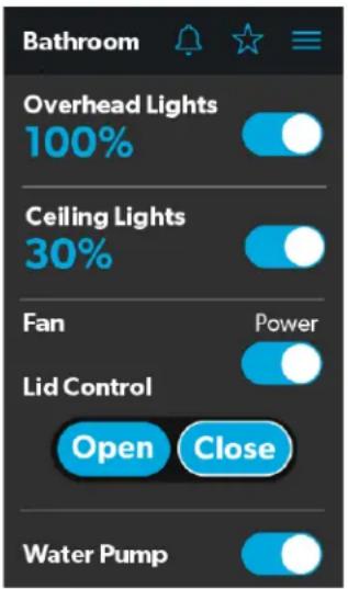
60 Bathroom Screen
From this screen, you can monitor and control the following functions:
- Lights: Use the toggle button for the desired light source to turn it off or on. The light source brightness is indicated as a percentage of the maximum intensity. Tap the brightness indicator for the desired light to adjust the intensity via vertical slider.
- Fan: Use the power toggle button to turn the fan motor on or off.

The lid must be open before the fan motor turns on. If the lid is closed when you attempt to turn the fan motor on, the lid will open automatically.
- Lid Control: Tap the Open or Close button to open or close the lids. A white outline around the button indicates the status of the lid.
- Water Pump: Use this toggle button to turn the water pump on or off.
4.1.14 Entry Screen
The Entry screen allows you to monitor and control the available components within the entry area of your RV, such as lighting and awnings.

Not all systems will include this screen. Control screens vary according to specific system configurations and available components.
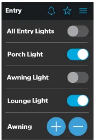
61 Entry Screen
From this screen, you can monitor and control the following functions:
- Entry Lighting: Use the toggle button for the desired light source to turn it off or on.

The All Entry Lights toggle button controls all three entry light sources (porch, awning, and lounge).
- Awnings: The Awning buttons allow you to extend or retract the awning. Awnings will have no control unless the parking brake is engaged.
If you attempt to extend or retract the awnings while the parking brake is not engaged, an alert appears.
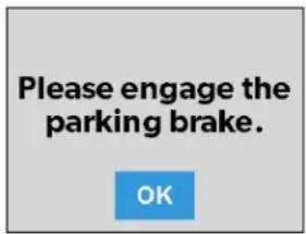
62 Parking Brake Alert
The Awning buttons function as follows:
- Tap the plus button (+) to extend the awning or the minus button (−) to retract the awning, and a pop-up message appears (assuming the parking brake is engaged).
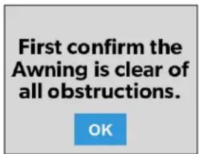
63 Awning Clear Message
- After you have verified that the awning is clear of obstructions, tap the OK button. The awning is now ready to extend or retract.
4.1.15 Clock Screen
The Clock screen allows you to monitor various system statuses, such as temperatures, time and date, and humidity.
This screen appears when the proximity sensor is out of the threshold distance (sensing range). For this screen to appear in standby mode, you must select the Clock standby option from the Settings screen.
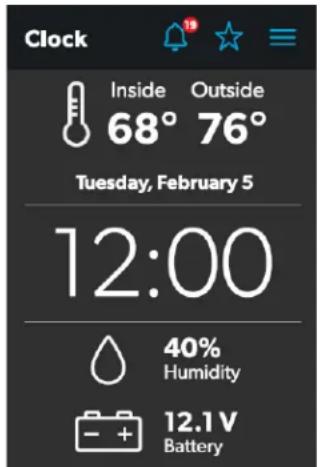
64 Clock Screen
From this screen, you can monitor the following system statuses:
- Use Temperature: This inside and outside temperatures are presented in either degrees Centigrade or Fahrenheit, which you can define from the Settings screen.
- Time and Date: The current time and date are displayed in the middle of the screen.
- Humidity: The humidity is shown as a percentage, coming from the onboard humidity sensor reading.
- Battery Levels: The battery level indicator monitors and displays the battery voltage level.
4.1.16 Notifications Screen
The Notifications screen allows you to monitor system fault status messages, such as blown fuse notifications.
This screen can be reached by tapping the bell icon at the top of any screen.
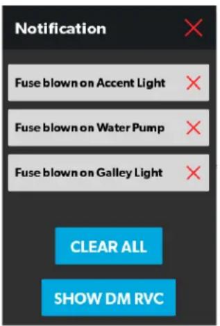
65 Notification Screen
From this screen, you can complete the following actions:
- View and Clear Notifications: Notifications appear with a banner when you open the Notifications screen.
- To clear an individual message, tap the exit (x) icon for that message.
- To clear all messages, tap the CLEAR ALL button.
- View Diagnostics Information: You can view diagnostics information for each notification.
- To view the diagnostics information for the notifications, tap the SHOW DM RVC button. The Diagnostics Message window appears.
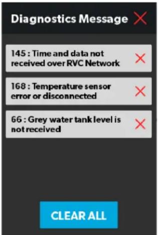
66 Diagnostics Message Window
- To clear an individual message, tap the exit (x) icon for that message.
- To clear all messages, tap the CLEAR ALL button.
4.2 Mobile Application Navigation and Use
This section describes how to use Dometic Interact from the downloadable mobile application. Refer to Touch-Screen Navigation and Use to learn how to operate the control using the onboard touch-screen display.
The mobile application is provided for your convenience. If the time and date on Dometic Interact are not correct, connect to the application through your phone or tablet. Once the mobile application is connected, the time and date on all Dometic Interact screens should be updated.
4.2.1 Prerequisites
Before you can connect to Dometic Interact with a mobile device, you must first download the System Control application onto your device.
natural_image
Icon showing a white van with Wi-Fi signal symbol inside a blue rounded square (no text or numbers)67 System Control App
- To download the application for Apple devices, visit the App Store.
- To download the application for Android devices, visit the Google Play Store.
After you have downloaded the application onto your mobile device, you can proceed to make the initial connection to the control.
4.2.2 Initial Connection
Complete the following steps to make the initial connection to the control from your mobile device:
- Move into the vicinity of the control to ensure successful connection.
-
Open your device settings and search for available Wi-Fi networks.
-
Locate and connect to the Wi-Fi network named LR-125.
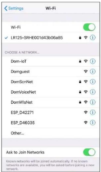
68 Wi-Fi Networks
- Enter the default password, which is YourPassPhrase.
You should now be successfully connected to Dometic Interact. You can proceed to change the password settings, if desired.
4.2.3 Password Settings
Complete the following steps to change the password:
- Tap the Settings icon once.
-
Tap Set URL, and then enter 192.168.8.1.
-
Tap the Settings icon once again, and then tap Network Page.
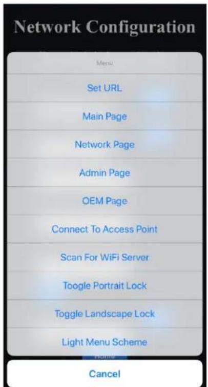
69 Network Configuration Menu
The following screen appears, where you can update your password as desired.
The password should be eight characters minimum. If you enter an incorrect password, you must press and hold the hard-reset button on the LR-125 for at least ten seconds.
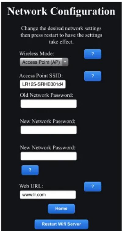
70 Network Configuration Update Menu
- After your password settings are updated, restart your Wi-Fi server and login with the new credentials.
When Access Point (AP) is selected for the Wireless Mode, then you can connect to the Wi-Fi server directly. When Infrastructure is selected, you are able to connect the Wi-Fi server module to your coach Ethernet/modem network by entering the user name and password of the network. If you enter the incorrect SSID or password, you will not be able to see the SSID or password information on the Dometic Interact screens. In this case, you must press and hold the hard-reset button on the LR-125 for at least ten seconds to return to factory default settings and reconnect.
4.2.4 Navigation and Use
After successful connection to the Dometic Interact Wi-Fi network, you are ready to begin using your mobile device to control the available components within your control configuration.
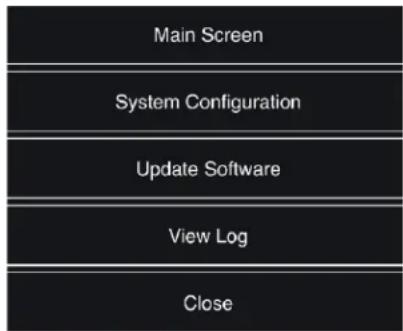
The mobile application landing page includes the following navigation options:
flowchart
graph TD
    A["Main Screen"] --> B["System Configuration"]
    B --> C["Update Software"]
    C --> D["View Log"]
    D --> E["Close"]
71 Landing Page Navigation
From the landing page, you can tap the following tabs to reach the desired screen:
- Main Screen: Tap this tab to reach the Main Navigation screen. Once you reach the Main Navigation screen, you can navigate to and use the main screens just as described in the Touch-Screen Navigation and Use section.
- System Configuration: Tap this tab to reach the System Configuration screen, where you can elect to show metric values, or enable the splash screen.
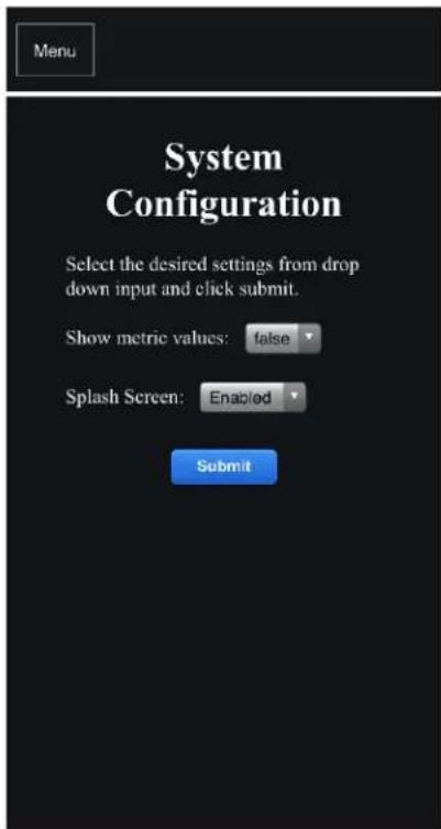
72 System Configuration Screen
- Update Software: Tap this tab to reach the Update WiFi Server Software screen, where you can view and manage the current software versions.
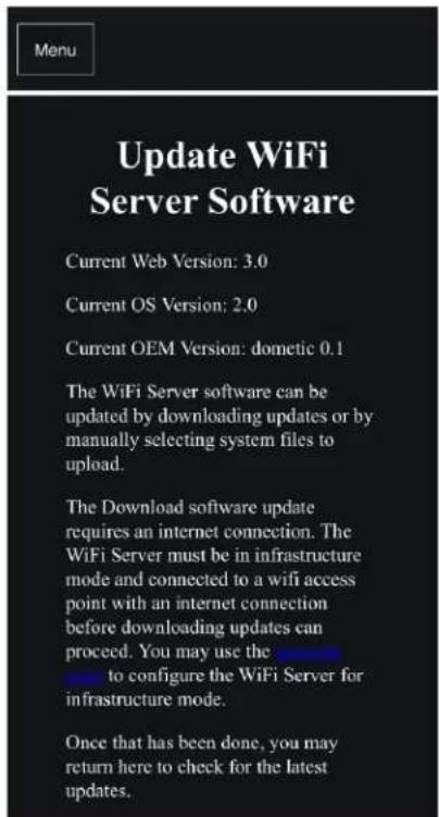
73 Update WiFi Server Software Screen
- View Log: Tap this tab to reach the LR 125 Boot Log screen, where you can choose to load the boot log for the Wi-Fi server.

74 Boot Log Screen
- Close: Tap this tab to close the mobile application.
5 Maintenance

WARNING: FIRE AND/OR ELECTRICAL SHOCK HAZARD
Use care when diagnosing, repairing, adjusting, and/or cleaning components on a powered unit. Failure to obey this warning could result in death or serious injury.
This section describes how to care for and maintain Dometic Interact. Refer to the following sections for information about care, cleaning, and preventive maintenance of the product.
5.1 Care and Cleaning

WARNING: FIRE AND/OR ELECTRICAL SHOCK HAZARD
Do not allow water to splash on or pour into a powered unit. Failure to obey this warning could result in death or serious injury.
NOTICE: Do not use abrasive cleaning materials or harsh chemicals on the touch-screen display, or damage to the product can occur.
If the touch-screen display becomes dirty, clean it with a soft, dry cloth, or use compressed air to loosen debris from the external orifices.
To remove hard dirt or grime, a slightly damp cloth with non-abrasive cleaning product is acceptable; however, take care not to damage the touch-screen display.
5.2 Preventive Maintenance
Use the following tips to ensure that your control continues to work properly:
- Ensure that the touch-screen display and PCB are operated between -4 °F to 140 °F (-20 °C to 60 °C).
- Ensure that you power on the control system occasionally during extended periods of non-use.
6 Troubleshooting

WARNING: FIRE AND/OR ELECTRICAL SHOCK HAZARD
Use care when diagnosing, repairing, adjusting, and/or cleaning components on a powered unit. Failure to obey this warning could result in death or serious injury.
This section describes how to troubleshoot common errors that may be encountered on Dometic Interact.

Refer to your inverter operating manual for troubleshooting information and to obtain customer service center information. Contact the manufacturer customer service department for inverter-related issues.
The table that follows describes some common errors that may be encountered with the control, their possible causes, and the recommended corrective actions.
Contact Dometic Customer Service at 1-800-544-4881, or email customersupportcenter@dometic.com for any other assistance.
| Error Possible Cause Recommended Corrective Action | ||
| There is power loss to Dometic Interact. | There is too much load on the circuit. Recycle power to the LCD by turning the breaker for Dometic Interact on and then back off. | |
| The screen does not wake up. You are not within range of the display proximity sensor. | Move closer to the LCD screen, or tap it once to turn it on. | |
| The coach lights are not turning on. | There is a blown software fuse, or the LED light needs to be replaced. | Examine the Dometic Interact Fuses screen and reset the blown fuse, or replace the LED bulb. |
| The AC will not turn on or off. The AC is in a time-delayed start up, or the AC circuit breaker has tripped. | The AC can take up to three minutes to respond to on/off commands. Reset the circuit breaker, if needed. | |
| You are unable to locate or connect to the LR-125 Wi-Fi server. | You are not within range of the LR-125 Wi-Fi module. | Seek a stronger Wi-Fi signal. |
| There is a water pump failure. There is a blown software fuse. Examine the Dometic Interact Fuses screen and reset the blown fuse, if applicable. | ||
| There is a satellite dish failure. There is a blown software fuse, or the satellite dish is disabled. | Examine the Dometic Interact Fuses screen and reset the blown fuse, or enable the satellite dish in the Settings screen. | |
| The touch-screen is unresponsive. | The system might be frozen. | Reboot the system by interrupting the power supply for ten seconds. |
| There is audio trouble. | The audio level is set too low. | Increase the default audio level in the Settings screen, or reboot the system. |
| The tank level readings are inaccurate. | The RV is not level or stationary. | Bring the RV to a complete stop and ensure that it is level. |
| The generator fails to exercise. | The AGS is turned off, the ignition safety interlock is enabled, or the settings are incorrect. | Turn on the AGS, remove the key from the vehicle ignition, or adjust the time settings. |
| The fan will not turn on, the fan lid will not open or close, or the fan lid closes by itself. | The system is frozen, or the rain sensor made the lids close and the fan turn off. | Reboot the system by interrupting the power supply for ten seconds. Verify if the fan has a rain sensor (Fan-Tastic fan model 7350 only). |
7 Disposal LIMITED ONE-YEAR WARRANTY

Place the packaging material in the appropriate recycling waste bins, whenever possible. Consult a local recycling center or specialist dealer for details about how to dispose of the product in accordance with all applicable national and local regulations.
LIMITED ONE-YEAR WARRANTY AVAILABLE AT WWW.DOMETIC.COM/WARRANTY.
IF YOU HAVE QUESTIONS, OR TO OBTAIN A COPY OF THE LIMITED WARRANTY FREE OF CHARGE, CONTACT:
DOMETIC CORPORATION CUSTOMER SUPPORT CENTER 1120 NORTH MAIN STREET ELKHART, INDIANA, USA 46514 1-800-544-4881 OPT 1
1 Écran de Navigation Principal
• Power (Alimentation)
• AGS
2 Écrans Climate (Climat)
13 Écran Lights (Lumières)
14 Écran Power (Alimentation)
15 Voyants de la Batterie
FR
Only run the generator in well-ventilated area.
OK
16 Alerte de ventilation
19 Écran AGS
20 Alerte de Ventilation
21 Alerte D'allumage
bar
| Tank | Percentage (%) | | :--- | :--- | | Fresh | 74 | | Grey | 58 | | Black | 18 | | LPG | 75 | Water Pump (approximate) indicated by a blue circle.24 Notification D'alarme
39 Notification de Mot de Passe Erroné
40 Notification de Limite de Mot de Passe
44 Fenêtre Date
65 Écran Notifications
68 Réseaux Wi-Fi
74 Écran Boot Log (Journal D'amorçage)
dometic.com/sales-offices


- Service Center & Dealer Locations
- Contents
- Explanation of Symbols and Safety Instructions 3
- General Information....3
- Intended Use....4
- Operation ....4
- Maintenance.... 34
- Troubleshooting.... 34
- Disposal 35
- LIMITED ONE-YEAR WARRANTY.... 35
- Explanation of Symbols and Safety Instructions
- Recognize Safety Information
- This is the safety alert symbol.
- Understand Signal Words
- DANGER!
- WARNING:
- CAUTION:
- Supplemental Directives
- U.S.A.
- Canada
- General Safety Messages
- WARNING: FIRE, IMPACT, AND/OR EXPLOSION HAZARD
- General Information
- Key Features
- Intended Use
- Operation
- WARNING: FIRE AND/OR IMPACT HAZARD.
- Touch-Screen Navigation and Use
- Main Navigation Screen and Icons
- Climate Screens
- Basic Air Conditioner Controls
- Advanced Climate Controls
- Mechanical Screen
- Basic Vent Fan Controls
- Advanced Vent Fan Controls
- Awning Controls
- Door Shade Controls
- Furniture Controls
- Lights Screen
- Power Screen
- Inverter Controls
- Battery Indicators
- Battery Indicators
- Charger Controls
- Generator Controls
- Advanced Inverter Settings
- AGS Screen
- Tanks Screen
- Alarms Screen
- Alarm Edit Window
- Pop-Up Time Window
- Sound Decision Window
- Sound Selection Window
- Program Decision Window
- Program Selection Window
- Naming Window
- Settings Screen
- General Info Section
- Config Mobile App Section
- Satellite Dish Option
- Start Page Section
- Default Room Section
- Standby Screen Section
- Set Date & Time Section
- Heat Mode Section
- Temperature System Option
- Language Section
- Brightness Mode Option
- Screen Brightness Option
- Proximity Sensitivity Option
- Audio Level Option
- Time Format Option
- Inverter Sleep Enable Option
- Programs Screen
- New Programs Window
- Program Settings Window
- Edit Program Window
- Naming Program Window
- Save Program Window
- Fuses Screen
- Bedroom Screen
- Bathroom Screen
- Entry Screen
- Clock Screen
- Notifications Screen
- Mobile Application Navigation and Use
- Prerequisites
- Initial Connection
- Password Settings
- Navigation and Use
- Maintenance
- WARNING: FIRE AND/OR ELECTRICAL SHOCK HAZARD
- Care and Cleaning
- Preventive Maintenance
- Troubleshooting
- Disposal LIMITED ONE-YEAR WARRANTY
- Only run the generator in well-ventilated area.
Brand : DOMETIC
Model : Interact Solution
Category : Air Conditioning