
W10446914 - Tumble drier MAYTAG - Free user manual and instructions
Find the device manual for free W10446914 MAYTAG in PDF.
| Product Type | Rectangular make-up air kit |
| Brand | Maytag |
| Model | W10446914 |
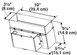
| Duct Dimensions | 8.3 x 25.4 cm (3¼ x 10 in) |
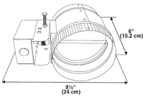
| Motorized Damper Dimensions | Diameter 15.2 cm (6 in), length 24 cm (9½ in) |
| Power Supply | 120 V AC, 60 Hz, 15 A, protected circuit |
| Intended Use | Only with exhaust hoods |
| Installation | By a qualified technician, according to local codes |
| Operation | Motorized damper opens at medium/high hood speed, closes at stop or low speed |
| Maintenance | Regularly check the outside air intake, clean filters |
| Safety | Disconnect power before maintenance; use only metal ducts |
| Parts Supplied | Rectangular duct, motorized damper, T10 Torx adapter |
| Warranty | 1 year parts only (labor not included) |
| Country of Destination | United States and Canada |
| Customer Service | 1-800-807-6777 (Canada) or 1-800-253-1301 (United States) |
Frequently Asked Questions - W10446914 MAYTAG
User questions about W10446914 MAYTAG
0 question about this device. Answer the ones you know or ask your own.
Ask a new question about this device
Download the instructions for your Tumble drier in PDF format for free! Find your manual W10446914 - MAYTAG and take your electronic device back in hand. On this page are published all the documents necessary for the use of your device. W10446914 by MAYTAG.
USER MANUAL W10446914 MAYTAG
MAKEUP AIR KITS FOR RECTANGULAR (3 ^1 /4 X 10" (8.3 X 25.4 CM)) OR ROUND (6, 8 AND 10" (15.2, 20.3 AND 25.4 CM)) VENT DUCT
Installation Instructions and Use & Care Guide
For questions about features, operation/performance, parts, accessories or service, call: 1-800-253-1301
or visit our website at www.whirlpool.com
In Canada, call 1-800-807-6777 or visit our website at www.whirlpool.ca
JUEGOS DE AIRE DE COMPLEMENTO PARA DUCTOS DE VENTILACIÓN RECTANGULARES (3 ^1/4 X 10" (8,3 X 25,4 CM)) O REDONDOS (6, 8 Y 10" (15,2, 20,3 Y 25,4 CM))
Au Canada, pour assistance, installation ou service, composer
natural_image
Technical line drawing of a mechanical assembly with cylindrical components and a housing (no text or symbols)IMPORTANT: READ AND SAVE THESE INSTRUCTIONS.
FOR RESIDENTIAL USE ONLY.
IMPORTANTE: LEA Y GUARDE ESTAS INSTRUCCIONES.
SÓLO PARA USO RESIDENCIAL.
IMPORTANT : LIRE ET CONSERVER CES INSTRUCTIONS.
POUR UTILISATION RÉSIDENTIELLE UNIQUEMENT.
LI30LA/W10463244A
TABLE OF CONTENTS
VENT SYSTEM SAFETY....2
INSTALLATION REQUIREMENTS....4
Tools and Parts 4
Location Requirements....4
Electrical Requirements 5
INSTALLATION INSTRUCTIONS....6
Prepare Location....6
Install Makeup Air Switch Duct....6
Install Motorized Damper....7
Make Electrical Connection ....7
Check Operation 8
Makeup Air Kit Maintenance....8
WIRING DIAGRAM 9
ASSISTANCE OR SERVICE....10
In the U.S.A. 10
In Canada 10
WARRANTY 11
ÍNDICE
DIAGRAMA DE CABLEADO....20
AYUDA O SERVICIO TÉCNICO....21
En los EE.UU. 21
GARANTÍA....21
TABLE DES MATIÈRES
SÉCURITÉ DES CIRCUITS DE VENTILATION....22
EXIGENCES D'INSTALLATION....24
ASSISTANCE OU SERVICE....31
Au Canada....31
GARANTIE....31
VENT SYSTEM SAFETY
Your safety and the safety of others are very important.
We have provided many important safety messages in this manual and on your appliance. Always read and obey all safety messages.

This is the safety alert symbol.
This symbol alerts you to potential hazards that can kill or hurt you and others.
All safety messages will follow the safety alert symbol and either the word "DANGER" or "WARNING."
These words mean:
DANGER
WARNING
You can be killed or seriously injured if you don't immediately follow instructions.
You can be killed or seriously injured if you don't follow instructions.
All safety messages will tell you what the potential hazard is, tell you how to reduce the chance of injury, and tell you what can happen if the instructions are not followed.
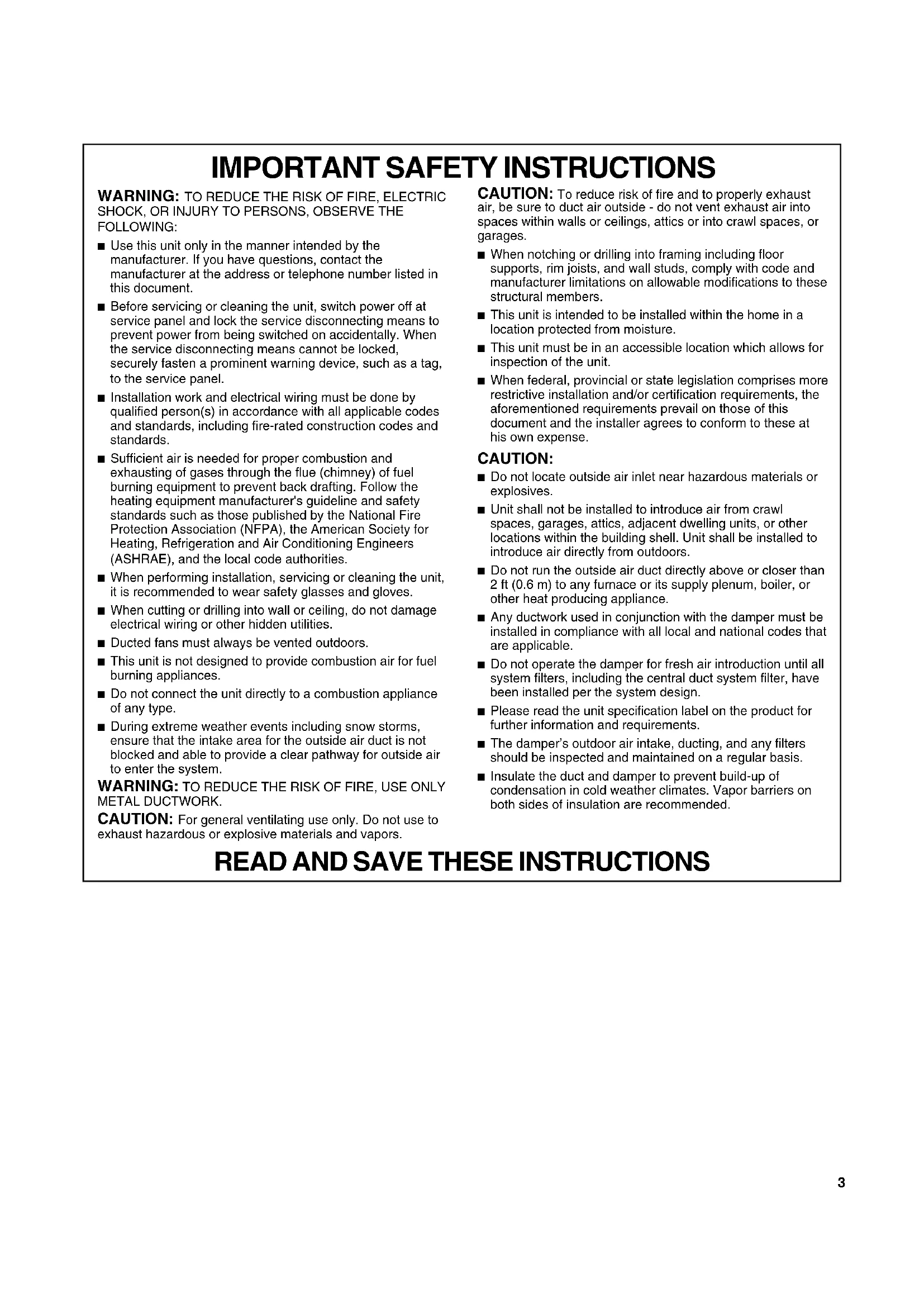
IMPORTANT SAFETY INSTRUCTIONS
WARNING: TO REDUCE THE RISK OF FIRE, ELECTRIC SHOCK, OR INJURY TO PERSONS, OBSERVE THE FOLLOWING:
■ Use this unit only in the manner intended by the manufacturer. If you have questions, contact the manufacturer at the address or telephone number listed in this document.
■ Before servicing or cleaning the unit, switch power off at service panel and lock the service disconnecting means to prevent power from being switched on accidentally. When the service disconnecting means cannot be locked, securely fasten a prominent warning device, such as a tag, to the service panel.
■ Installation work and electrical wiring must be done by qualified person(s) in accordance with all applicable codes and standards, including fire-rated construction codes and standards.
■ Sufficient air is needed for proper combustion and exhausting of gases through the flue (chimney) of fuel burning equipment to prevent back drafting. Follow the heating equipment manufacturer's guideline and safety standards such as those published by the National Fire Protection Association (NFPA), the American Society for Heating, Refrigeration and Air Conditioning Engineers (ASHRAE), and the local code authorities.
■ When performing installation, servicing or cleaning the unit, it is recommended to wear safety glasses and gloves.
■ When cutting or drilling into wall or ceiling, do not damage electrical wiring or other hidden utilities.
■ Ducted fans must always be vented outdoors.
■ This unit is not designed to provide combustion air for fuel burning appliances.
■ Do not connect the unit directly to a combustion appliance of any type.
■ During extreme weather events including snow storms, ensure that the intake area for the outside air duct is not blocked and able to provide a clear pathway for outside air to enter the system.
WARNING: TO REDUCE THE RISK OF FIRE, USE ONLY METAL DUCTWORK.
CAUTION: For general ventilating use only. Do not use to exhaust hazardous or explosive materials and vapors.
CAUTION: To reduce risk of fire and to properly exhaust air, be sure to duct air outside - do not vent exhaust air into spaces within walls or ceilings, attics or into crawl spaces, or garages.
■ When notching or drilling into framing including floor supports, rim joists, and wall studs, comply with code and manufacturer limitations on allowable modifications to these structural members.
■ This unit is intended to be installed within the home in a location protected from moisture.
■ This unit must be in an accessible location which allows for inspection of the unit.
■ When federal, provincial or state legislation comprises more restrictive installation and/or certification requirements, the aforementioned requirements prevail on those of this document and the installer agrees to conform to these at his own expense.
CAUTION:
■ Do not locate outside air inlet near hazardous materials or explosives.
■ Unit shall not be installed to introduce air from crawl spaces, garages, attics, adjacent dwelling units, or other locations within the building shell. Unit shall be installed to introduce air directly from outdoors.
■ Do not run the outside air duct directly above or closer than 2 ft (0.6 m) to any furnace or its supply plenum, boiler, or other heat producing appliance.
■ Any ductwork used in conjunction with the damper must be installed in compliance with all local and national codes that are applicable.
■ Do not operate the damper for fresh air introduction until all system filters, including the central duct system filter, have been installed per the system design.
■ Please read the unit specification label on the product for further information and requirements.
■ The damper's outdoor air intake, ducting, and any filters should be inspected and maintained on a regular basis.
■ Insulate the duct and damper to prevent build-up of condensation in cold weather climates. Vapor barriers on both sides of insulation are recommended.
READ AND SAVE THESE INSTRUCTIONS
INSTALLATION REQUIREMENTS
Tools and Parts
Gather the required tools and parts before starting installation. Read and follow the instructions provided with any tools listed here.
Tools needed
■ Drill with 1¼" (3.0 cm) drill bit
■ Pencil
■ Wire stripper or utility knife
■ Tape measure or ruler
■ Pliers
■ Caulking gun and weatherproof caulking compound
■ Jigsaw or keyhole saw
■ Flat-blade screwdriver
■ Metal snips
■ Phillips screwdriver
Parts needed (quantities of parts are determined by installation requirements)
■ Home power supply cable
■ Vent clamps
■ Wall or roof cap
■ 6" (15.2 cm) diameter vent duct for connection to motorized damper. (Lengths are determined by installation requirements.)
■ UL listed wire connectors
■ 1/2" (12.7 mm) UL listed or CSA approved strain relief
Parts supplied
Remove parts from packages. Check that all parts are included.
3¼ x 10" (8.3 x 25.4 cm) Rectangular Makeup Air Kit (W10446914)
■ 3¼ x 10" (8.3 x 25.4 cm) makeup air switch duct
■ 6" (15.2 cm) motorized damper
■ T10 Torx ^ adapter
6" (15.2 cm) Round Makeup Air Kit (W10446915)
■ 6" (15.2 cm) round makeup air switch duct
■ 6" (15.2 cm) motorized damper
■ T10 Torx ^37 adapter
8" (20.3 cm) Round Makeup Air Kit (W10446916)
■ 8" (20.3 cm) round makeup air switch duct
■ 6" (15.2 cm) motorized damper
■ T10 Torx ^ adapter
10" (25.4 cm) Round Makeup Air Kit (W10446917)
■ 10" (25.4 cm) round makeup air switch duct
■ 2 - 6" (15.2 cm) motorized damper
■ T10 Torx ^ adapter
Location Requirements
IMPORTANT: Observe all governing codes and ordinances.
Have a qualified technician install this makeup air kit. It is the installer's responsibility to comply with installation clearances specified.
Grounded electrical outlet is required. See "Electrical Requirements" section.
All openings in ceiling and wall must be sealed.
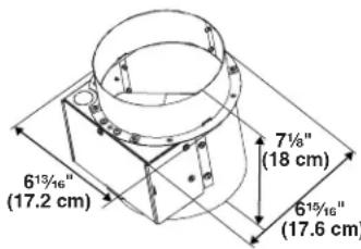
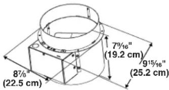
Product Dimensions
Makeup Air Switch Duct (installed on the range hood)
6" (15.2 cm) Kit W10446915 8" (20.3 cm) Kit W10446916
10" (25.4 cm) Kit W10446917
3¼" x 10" (8.3 x 25.4 cm) Kit W10446914
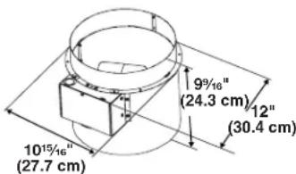
6" (15.2 cm) Motorized Damper (installed for outside air intake)
Planning the Installation
Planning the Makeup Air Switch Duct installation
This makeup air kit can only be used with vented range hoods. The makeup air kit must match the vent transition size for your range hood.
Planning the Motorized Damper installation
Planning the installation first requires selecting the most appropriate installation approach. The following illustrations offer suggestions for the most effective installation approach by considering a few important factors.
Typical Installations
Installations will vary according to the location in the home where the motorized damper is installed and which makeup air kit is used. The following illustrations can be used as a reference guide for your installation. Always comply with all governing codes and ordinances.
NOTE: The 10" (25.4 cm) round Makeup Air Kit must be installed with 2 independent incoming air supply ducts. Use the 2 motorized dampers supplied with the kit (1 each, in the incoming fresh air supply ducts).
Motorized Damper Connected to Return Side of Central Duct System
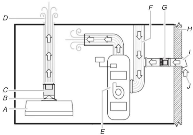
A. Range hood
B. Vent transition
C. Makeup air switch duct
D. Range hood exhaust
E. HVAC system
F. Return air central system
G. Motorized damper
H. Wall or roof
I. Wall/roof cap
J. Outside air
Motorized Damper and Outside Air Connected Directly to a Ceiling, Floor or Wall Register
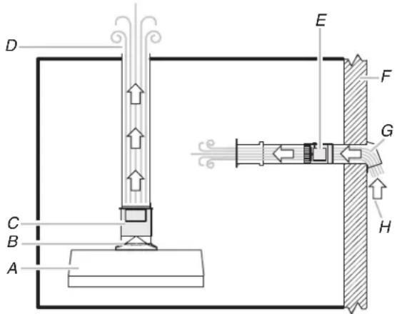
A. Range hood
B. Vent transition
C. Makeup air switch duct
D. Range hood exhaust
E. Motorized damper
F. Wall or roof
G. Wall/roof cap
H. Outside air
Electrical Requirements
Observe all governing codes and ordinances.
Ensure that the electrical installation is adequate and in conformance with National Electrical Code, ANSI/NFPA 70 (latest edition), or CSA Standards C22.1-94, Canadian Electrical Code, Part 1 and C22.2 No. 0-M91 (latest edition) and all local codes and ordinances.
If codes permit and a separate ground wire is used, it is recommended that a qualified electrician determine that the ground path is adequate.
A copy of the above code standards can be obtained from:
National Fire Protection Association
1 Batterymarch Park
Quincy, MA 02169-7471
CSA International
8501 East Pleasant Valley Road
Cleveland, OH 44131-5575
■ A 120 volt, 60 Hz., AC only, 15-amp, fused electrical circuit is required.
■ If the house has aluminum wiring, follow the procedure below:
- Connect a section of solid copper wire to the pigtail leads.
- Connect the aluminum wiring to the added section of copper wire using special connectors and/or tools designed and UL listed for joining copper to aluminum.
Follow the electrical connector manufacturer's recommended procedure. Aluminum/copper connection must conform with local codes and industry accepted wiring practices.
■ Wire sizes must conform to the requirements of the National Electrical Code, ANSI/NFPA 70 (latest edition), or CSA Standards C22.1-94, Canadian Electrical Code, Part 1 and C22.2 No. 0-M91 (latest edition) and all local codes and ordinances.
■ A UL or CSA listed strain relief must be provided at each end of the power supply cable/conduit (at the junction boxes).
INSTALLATION INSTRUCTIONS
Prepare Location
■ It is recommended that the Makeup Air Kit is installed at the same time the range hood is installed.
■ If the range hood is already installed, you will need to remove the vent covers and the vent duct system from the range hood. Consult your hood manual. (See illustrations in the "Install Makeup Air Switch Duct" section.)
■ Makeup air switch duct must be assembled to vent duct in the vertical (upward) position only.
Install Makeup Air Switch Duct
Wall or Island Mount Range Hood Models
6" (15.2 cm) and 8" (20.3 cm) Round Makeup Air Switch Duct (From kits W10446915 and W10446916)
- Disconnect power.
- If range hood is installed, remove the vent system and its vent covers and put them aside.
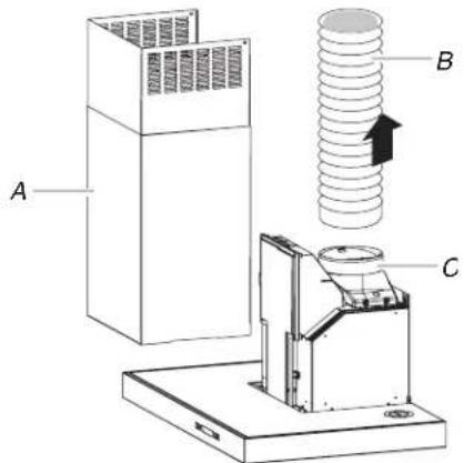
A. Vent covers
B. Vent system
C. Vent transition
- Install the makeup air switch duct to the vent transition and seal connection with vent clamp. The terminal box cover should be to the front or to either side for wiring access.
A. Terminal box cover
B. Airflow
C. Makeup air switch duct D. Vent transition
- Install the range hood using the Installation Instructions that came with range hood.
NOTE: If range hood is already installed, replace the vent system onto the makeup air switch duct and seal connections with vent clamps.
10" (25.4 cm) Round Makeup Air Switch Duct (From kit W10446917)
- Disconnect power.
- If range hood is installed, remove the vent system and its vent covers and put them aside.
A. Vent covers
B. Vent system
C. Vent transition
- Install the makeup air switch duct to the vent transition and seal connection with vent clamp.
NOTE: The terminal box should be oriented to either the right or left side of the hood for wiring access.
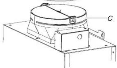
natural_image
Technical line drawing of a mechanical device with labeled component C (no text or symbols beyond label)A. Terminal box cover
B. Makeup air switch duct
C. Vent transition
- Install the range hood using the Installation Instructions that came with range hood.
NOTE: If range hood is already installed, replace the vent system onto the makeup air switch duct and seal connections with vent clamps.
Under-Cabinet Mount Range Hood Models
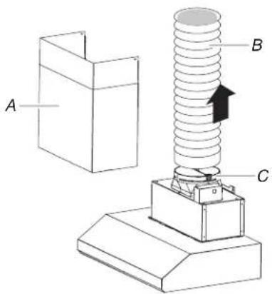
3¼" x 10" (8.3 x 25.4 cm) Rectangular Makeup Air Switch Duct (From kit W10446914)
NOTE: The range hood must be mounted before the makeup air switch duct is attached. Use the Installation Instructions that came with the range hood.
- Disconnect power.
- If range hood is installed, remove the vent system and put it aside.
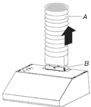
A. Vent system
B. Vent transition
- Install the makeup air switch duct to the vent transition and seal connection. The terminal box cover should be to the front for wiring access.
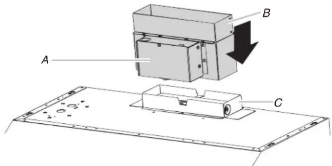
A. Terminal box cover
B. Makeup air switch duct
C. Vent transition
- Install the vent system onto the makeup air switch duct and seal connections. Finalize the installation of the range hood using the Installation Instructions that came with range hood.
Install Motorized Damper
IMPORTANT: Observe all governing codes and ordinances.
Proper location of the outside air intake is necessary to ensure that the damper can reliably allow fresh air to enter the home. The following requirements for the location of the outside air intake must be met:
■ Outside air intake is to be located a minimum of 10 ft (3.05 m) from combustion appliance vents, chimneys, plumbing stacks, and bathroom, laundry, or kitchen exhaust vents.
■ Outside air intake is to be placed high enough above grade to prevent blockage from snow or other debris such as leaves, and at a minimum of 1 ft (30.5 cm) above grade.
■ The damper should be installed to draw air directly from outdoors. Makeup air should not be drawn from crawl spaces, garages, attics, adjacent dwelling units, or any enclosed part of the building.
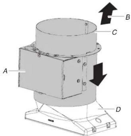
Install the motorized damper as shown. See the illustrations in "Typical Installations" in the "Location Requirements" section for reference.
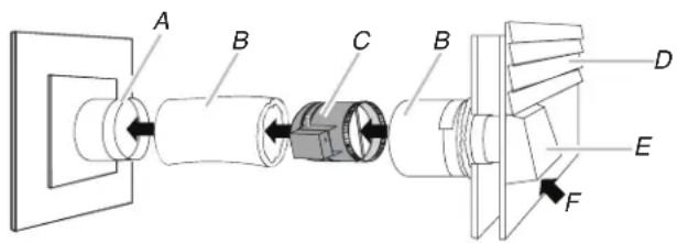
A. Wall register
B. Ducts
C. 6" (15.2 cm) motorized damper
D. Wall/roof
E. Wall or roof cap
F. Airflow
Make Electrical Connection
WARNING

Electrical Shock Hazard
Disconnect power before servicing.
Replace all parts and panels before operating.
Failure to do so can result in death or electrical shock.
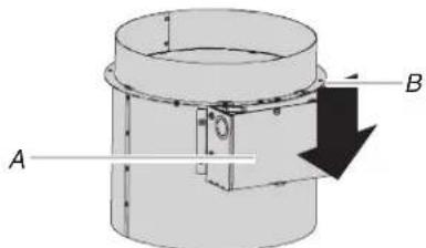
To Remove and Install Motorized Damper Terminal Box Cover
- Press in and lift up on the end of terminal box cover with wire hole to remove cover.
- To install terminal cover, place tab on solid end of cover into small slot in motor mount, swing cover over motor and slip second tab into larger slot.
Make the Electrical Connection
- Disconnect power.
- Determine the location where the wiring conduit will be routed through the ceiling or wall between the makeup air switch duct and the motorized damper.
- Drill a hole at this location.
- Locate the electrical terminal boxes in the makeup air switch duct and the motorized damper.
Remove the terminal box covers and set the covers and screws aside. - Determine the knockouts in terminal boxes for motorized damper, makeup air switch duct and house junction box that will be used.
Remove knockouts and install a 12 " (12.7 mm) UL listed or CSA approved strain relief at each location. - Run separate wiring between the house junction box and the terminal boxes for the motorized damper and the makeup air switch duct.
WARNING

Electrical Shock Hazard
Disconnect power before servicing.
Connect ground wire to green ground wire in terminal box.
Replace all parts and panels before operating.
Failure to do so can result in death, fire, or electrical shock.
- Connect green (yellow/green) wires from makeup air switch duct and motorized damper to house ground using UL listed wire connectors.
- Connect brown wire from makeup air switch duct to the black wire(s) from the motorized damper using UL listed wire connectors.
-
Connect black wire from makeup air switch duct to the house line black wire using a UL listed wire connector.
-
Connect the white wire(s) from the motorized damper to the house neutral white wire(s) using UL listed wire connectors.
NOTE: The 10" (25.4 cm) Makeup Air Kit must be installed with 2 motorized dampers. The lightest figure shown is the connection for the second motorized damper.
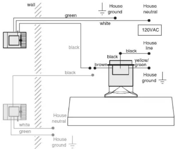
10" (25.4 cm) Makeup air installation
Check Operation
Once the make up air switch duct and the motorized damper(s) are installed, the installer should confirm that the motorized damper opens and closes in conjunction with signals from the hood.
■ The motorized damper should close or be closed when the range hood speed switch is Off or On at low speed.
■ The motorized damper should open when the range hood speed switch is set at medium speed or higher.
A qualified HVAC contractor should also ensure the proper operation and venting of all combustion equipment in the home.
Makeup Air Kit Maintenance
Regular maintenance is necessary to ensure the proper operation of the makeup air system. Failure to conduct routine maintenance can reduce the ability of the damper to introduce fresh air into the home. Regular maintenance should include the following activities:
■ Maintain a clear opening at the outdoor end cap, keeping snow, leaves or vegetation from building up at the end cap.
■ Clean or replace the interior filter(s) that serve to filter fresh air before it enters the home.
■ During regular HVAC maintenance, have the mechanical contractor inspect the damper system for proper operation.
WIRING DIAGRAM
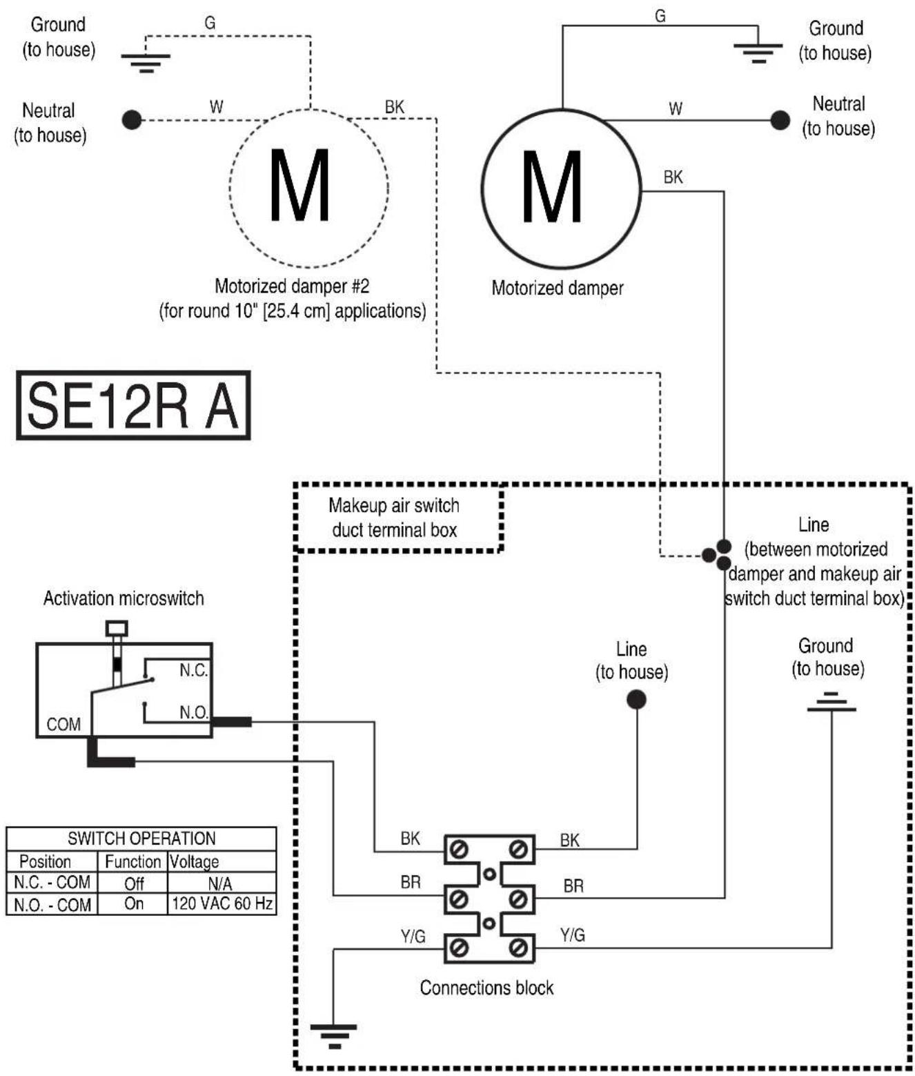
flowchart
graph TD
    A["SE12R A"] --> B["Motorized damper #2 (for round 10" [25.4 cm"] applications)]
    B --> C["Ground (to house)"]
    B --> D["Neutral (to house)"]
    B --> E["Motorized damper"]
    E --> F["Ground (to house)"]
    E --> G["Motorized damper"]
    G --> H["Ground (to house)"]
    G --> I["Motorized damper"]
    I --> J["Line (between motorized damper and makeup air switch duct terminal box)"]
    J --> K["Line (to house)"]
    J --> L["Line (between motorized damper and makeup air switch duct terminal box)"]
    M["Activation microswitch"] --> N["N.C. COM"]
    N --> O["N.O."]
    O --> P["BK"]
    P --> Q["BK"]
    Q --> R["BR"]
    R --> S["BR"]
    S --> T["Y/G"]
    T --> U["Y/G"]
    U --> V["Connections block"]
    W["SWITCH OPERATION"] --> X["Position"]
    W --> Y["Function"]
    W --> Z["Voltage"]
    W --> AA["N.C. - COM"]
    W --> AB["Off"]
    W --> AC["N.O. - COM"]
    W --> AD["On"]
    W --> AE["120 VAC 60 Hz"]
ASSISTANCE OR SERVICE
When calling for assistance or service, please know the purchase date and the complete model and serial number of your appliance. This information will help us to better respond to your request.
If you need replacement parts
If you need to order replacement parts, we recommend that you use only factory specified parts. Factory specified parts will fit right and work right because they are made with the same precision used to build every new appliance. To locate factory specified replacement parts in your area, call us or your nearest designated service center.
In the U.S.A.
Call the Whirlpool Customer eXperience Center toll free: 1-800-253-1301.
Our consultants provide assistance with:
■ Features and specifications on our full line of appliances.
■ Installation information.
■ Use and maintenance procedures.
■ Accessory and repair parts sales.
■ Specialized customer assistance (Spanish speaking, hearing impaired, limited vision, etc.).
■ Referrals to local dealers, repair parts distributors and service companies. Whirlpool designated service technicians are trained to fulfill the product warranty and provide after-warranty service, anywhere in the United States.
To locate the Whirlpool designated service company in your area, you can also look in your telephone directory Yellow Pages.
For further assistance
If you need further assistance, you can write to Whirlpool
Corporation with any questions or concerns at:
Whirlpool Brand Home Appliances
Customer eXperience Center
553 Benson Road
Benton Harbor, MI 49022-2692
Please include a daytime phone number in your correspondence.
In Canada
Call the Whirlpool Canada LP Customer eXperience Centre toll free: 1-800-807-6777.
Our consultants provide assistance with:
■ Features and specifications on our full line of appliances.
■ Use and maintenance procedures.
■ Accessory and repair parts sales.
■ Referrals to local dealers, repair parts distributors, and service companies. Whirlpool Canada LP designated service technicians are trained to fulfill the product warranty and provide after-warranty service, anywhere in Canada.
For further assistance
If you need further assistance, you can write to Whirlpool
Canada LP with any questions or concerns at:
Customer eXperience Centre
Whirlpool Canada LP
200 - 6750 Century Ave.
Mississauga, Ontario L5N 0B7
Please include a daytime phone number in your correspondence.
WHIRLPOOL® COOKING ACCESSORY LIMITED WARRANTY
1 YEAR LIMITED WARRANTY (PARTS ONLY - LABOR NOT INCLUDED)
For one year from the date of this purchase, when the Cooking Accessory is installed, operated, and maintained according to instructions attached to or furnished with this product, Whirlpool Corporation or Whirlpool Canada LP (hereafter "Whirlpool") will, at its sole option, deliver factory specified replacement parts to correct defects in materials or workmanship or replace the product. If replaced, your product will be covered by the remaining one year limited warranty of the original unit.
YOUR SOLE AND EXCLUSIVE REMEDY UNDER THE LIMITED WARRANTY SHALL BE PRODUCT REPAIR OR REPLACEMENT AT OUR DISCRETION AS PROVIDED HEREIN. This limited warranty is valid in the United States and Canada and applies only when the the Cooking Accessory is used in the country in which it was purchased. This limited warranty is effective from the date of the original consumer purchase. Proof of original purchase date is required to obtain factory specified replacement parts or product replacement under this limited warranty.
ITEMS EXCLUDED FROM WARRANTY
This warranty does not cover:
- In-home service including, but not limited to, service calls to correct the installation of your Cooking Accessory or to instruct you on how to use your product.
- Factory specified replacement parts or product replacement when your Cooking Accessory is used for other than normal, single-family household use or when it is used in a manner contrary to published user or operator instructions and/or installation instructions.
- Damage resulting from accident, alteration, misuse, abuse, fire, floods, acts of God, improper installation not in accordance with local electrical and plumbing codes, or use of consumables or cleaning products not approved by Whirlpool Corporation.
- Cosmetic damage, including scratches, dents, chips, or other damage to the finish of your Cooking Accessory, unless such damage results from defects in materials or workmanship and is reported to Whirlpool within 30 days from the date of purchase.
- Factory specified parts or product replacement resulting from unauthorized modifications made to the product.
- Travel, transportation, or shipping expenses outside of the expenses specifically designated in this Cooking Accessory limited warranty.
- Removal or reinstallation of trim, decorative panels, cabinetry, drywall or other built-in fixtures for removal and/or replacement of product.
The cost of repair or replacement under these excluded circumstances shall be borne by the customer.
If you reside in the United States or Canada and need to submit a request for warranty service:
- Customers in the U.S.A. should call our service office at 1-800-253-1301, from 8:00 a.m. to 8:00 p.m., Monday through Friday, Eastern Standard Time. Customers in Canada should call our service office at 1-800-807-6777, from 8:00 a.m. to 6:30 p.m., Monday through Friday, Eastern Standard Time.
- Give the consultant your model, serial number, and shipping address (no P.O. Box numbers, please).
- The consultant will advise whether the Cooking Accessory qualifies for factory specified replacement parts or product replacement.
- You may be directed to forward the product to a Whirlpool designated service center. You are responsible for insurance and freight to the designated service center. Please include your name and address on a piece of paper, along with proof of purchase (register receipt, charge slip, etc.). The product should be properly packaged to avoid damage in transit, as we will not be responsible for any such damage.
- Whirlpool will return the specified unit or, at our option, an identical or comparable Cooking Accessory, or factory specified replacement parts, to your door free of charge.
DISCLAIMER OF IMPLIED WARRANTIES
IMPLIED WARRANTIES, INCLUDING ANY LIMITED WARRANTY OF MERCHANTABILITY OR LIMITED WARRANTY OF FITNESS FOR A PARTICULAR PURPOSE, ARE LIMITED TO 1 YEAR OR THE SHORTEST PERIOD ALLOWED BY LAW. Some states and provinces do not allow limitations on the duration of implied warranties of merchantability or fitness, so this limitation may not apply to you. This warranty gives you specific legal rights, and you also may have other rights that vary from state to state or province to province.
LIMITATIONS OF REMEDIES; EXCLUSION OF INCIDENTAL AND CONSEQUENTIAL DAMAGES
YOUR SOLE AND EXCLUSIVE REMEDY UNDER THIS LIMITED WARRANTY SHALL BE PRODUCT REPAIR OR REPLACEMENT AT OUR DISCRETION AS PROVIDED HEREIN. WHIRLPOOL SHALL NOT BE RESPONSIBLE FOR INCIDENTAL OR CONSEQUENTIAL DAMAGES. Some states and provinces do not allow the exclusion or limitation of incidental or consequential damages, so these limitations may not apply to you. This warranty gives you specific legal rights, and you also may have other rights that vary from state to state or province to province.
Outside the 50 United States and Canada, this warranty does not apply. Contact your authorized Whirlpool dealer to determine if another warranty applies. If you need service, in the U.S.A., call 1-800-422-1230. In Canada, call 1-800-807-6777. 12/11
Keep this book and your sales slip together for future reference. You must provide proof of purchase or installation date for in-warranty service.
Write down the following information about your Cooking Accessory to better help you obtain assistance or service if you ever need it. You will need to know your complete model number.
Model number
Serial number
Purchase date
National Fire Protection Association,
1 Batterymarch Park
Quincy, MA 02169-7471
CSA International
8501 East Pleasant Valley Road
Cleveland, OH 44131-5575
National Fire Protection Association
1 Batterymarch Park
Quincy, MA 02169-7471
CSA International
8501 East Pleasant Valley Road
Cleveland, OH 44131-5575
A. Cache-conduits
ASSISTANCE OU SERVICE

- MAKEUP AIR KITS FOR RECTANGULAR (3 1 /4 X 10" (8.3 X 25.4 CM)) OR ROUND (6, 8 AND 10" (15.2, 20.3 AND 25.4 CM)) VENT DUCT
- JUEGOS DE AIRE DE COMPLEMENTO PARA DUCTOS DE VENTILACIÓN RECTANGULARES (3 1/4 X 10" (8,3 X 25,4 CM)) O REDONDOS (6, 8 Y 10" (15,2, 20,3 Y 25,4 CM))
- TABLE OF CONTENTS
- VENT SYSTEM SAFETY....2
- INSTALLATION REQUIREMENTS....4
- INSTALLATION INSTRUCTIONS....6
- WIRING DIAGRAM 9
- ASSISTANCE OR SERVICE....10
- WARRANTY 11
- ÍNDICE
- DIAGRAMA DE CABLEADO....20
- AYUDA O SERVICIO TÉCNICO....21
- GARANTÍA....21
- TABLE DES MATIÈRES
- SÉCURITÉ DES CIRCUITS DE VENTILATION....22
- EXIGENCES D'INSTALLATION....24
- ASSISTANCE OU SERVICE....31
- GARANTIE....31
- VENT SYSTEM SAFETY
- Your safety and the safety of others are very important.
- DANGER
- WARNING
- IMPORTANT SAFETY INSTRUCTIONS
- CAUTION:
- READ AND SAVE THESE INSTRUCTIONS
- INSTALLATION REQUIREMENTS
- Tools and Parts
- Tools needed
- Parts needed (quantities of parts are determined by installation requirements)
- Parts supplied
- 3¼ x 10" (8.3 x 25.4 cm) Rectangular Makeup Air Kit (W10446914)
- 6" (15.2 cm) Round Makeup Air Kit (W10446915)
- 8" (20.3 cm) Round Makeup Air Kit (W10446916)
- 10" (25.4 cm) Round Makeup Air Kit (W10446917)
- Location Requirements
- Product Dimensions
- Makeup Air Switch Duct (installed on the range hood)
- Planning the Installation
- Planning the Makeup Air Switch Duct installation
- Planning the Motorized Damper installation
- Typical Installations
- Motorized Damper Connected to Return Side of Central Duct System
- Motorized Damper and Outside Air Connected Directly to a Ceiling, Floor or Wall Register
- Electrical Requirements
- INSTALLATION INSTRUCTIONS
- Prepare Location
- Install Makeup Air Switch Duct
- Wall or Island Mount Range Hood Models
- Under-Cabinet Mount Range Hood Models
- 3¼" x 10" (8.3 x 25.4 cm) Rectangular Makeup Air Switch Duct (From kit W10446914)
- Install Motorized Damper
- Make Electrical Connection
- Electrical Shock Hazard
- To Remove and Install Motorized Damper Terminal Box Cover
- Make the Electrical Connection
- Check Operation
- Makeup Air Kit Maintenance
- ASSISTANCE OR SERVICE
- If you need replacement parts
- In the U.S.A.
- Our consultants provide assistance with:
- For further assistance
- In Canada
- WHIRLPOOL® COOKING ACCESSORY LIMITED WARRANTY
- YEAR LIMITED WARRANTY (PARTS ONLY - LABOR NOT INCLUDED)
- ITEMS EXCLUDED FROM WARRANTY
- This warranty does not cover:
- If you reside in the United States or Canada and need to submit a request for warranty service:
- DISCLAIMER OF IMPLIED WARRANTIES
- LIMITATIONS OF REMEDIES; EXCLUSION OF INCIDENTAL AND CONSEQUENTIAL DAMAGES
- Keep this book and your sales slip together for future reference. You must provide proof of purchase or installation date for in-warranty service.
- ASSISTANCE OU SERVICE
Brand : MAYTAG
Model : W10446914
Category : Tumble drier