Profile GCG1580LSS - Built-in compactor GE - Free user manual and instructions
Find the device manual for free Profile GCG1580LSS GE in PDF.
| Product Type | Built-in Compactor |
| Brand | GE |
| Model | Profile GCG1580LSS |
| Width | 38 cm (15 in) |
| Electrical Supply | 120 V, 60 Hz, dedicated 15 or 20 A circuit protected by time-delay fuse or circuit breaker |
| Grounding | Required, three-prong plug, do not use an adapter |
| Circuit Capacity | 15 or 20 amps |
| Intended Use | Residential, built-in installation only |
| Operation | Automatic compaction cycle lasting less than 30 seconds, pedal activation |
| Required Front Clearance | 58.4 cm (23 in) for full drawer opening |
| Right Side Clearance | 15.2 cm (6 in) for bag removal |
| Maximum Custom Panel Weight | 5.4 kg (12 lb) |
| Installation Hardware Included | 6 mounting screws, 2 retaining brackets, 2 mounting clips |
| Cleaning | Mild liquid detergent and water solution |
| Repairability | Parts available by order (GE customer service) |
| Warranty | Refer to the user manual for details |
| Customer Service (Canada) | 1.800.561.3344 |
| Customer Service (USA) | 1.800.423.2737 |
| Website (Canada) | www.electromagersge.ca |
| Website (USA) | GEAppliances.com |
Frequently Asked Questions - Profile GCG1580LSS GE
User questions about Profile GCG1580LSS GE
0 question about this device. Answer the ones you know or ask your own.
Ask a new question about this device
Download the instructions for your Built-in compactor in PDF format for free! Find your manual Profile GCG1580LSS - GE and take your electronic device back in hand. On this page are published all the documents necessary for the use of your device. Profile GCG1580LSS by GE.
USER MANUAL Profile GCG1580LSS GE
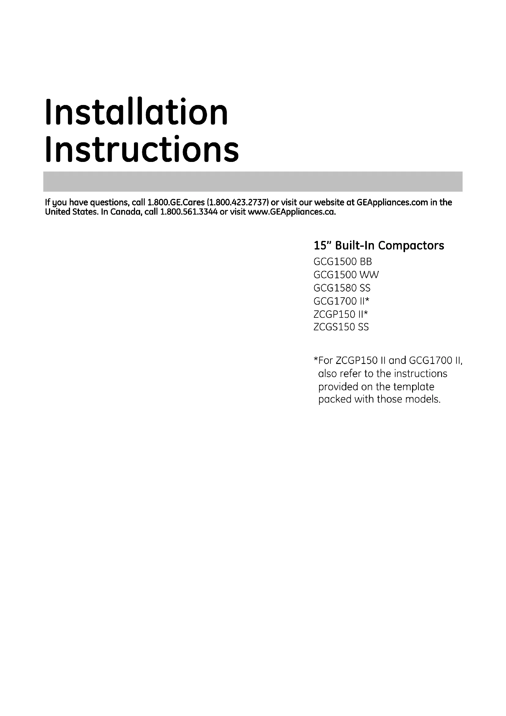
Installation Instructions
If you have questions, call 1.800.GE.Cares (1.800.423.2737) or visit our website at GEAppliances.com in the United States. In Canada, call 1.800.561.3344 or visit www.GEApliances.ca.
15" Built-In Compactors
GCG1500 BB
GCG1500 WW
GCG1580 SS
GCG1700 II*
ZCGP150 II*
ZCGS150 SS
*For ZCGP150 II and GCG1700 II, also refer to the instructions provided on the template packed with those models.

BEFORE YOU BEGIN
Read these instructions completely and carefully.
-IMPORTANT - Save these instructions for local inspector's use.
-IMPORTANT - Observe all governing codes and ordinances.
Note to Installer - Be sure to leave these instructions with the Consumer.
Note to Consumer - Keep these instructions with your Owner's Manual for future reference.
- Skill Level - Installation of this appliance requires basic mechanical and electrical skills.
Completion time - 1 hour.
- Proper installation is the responsibility of the installer.
- Product failure due to improper installation is not covered under the Warranty. See Owner's Manual for warranty information.
IMPORTANT
- This compactor is for household use only.
- Use this compactor only for its intended purpose.
- This compactor is designed for BUILT-IN installations ONLY.
WARNING!
Do not allow items to fall or collect behind the compactor. Failure to follow this instruction could result in a fire.
CAUTION:
For personal safety, remove house fuse or open circuit breaker before beginning installation to avoid severe or fatal shock injury.
While performing installations described in this book, safety glasses or goggles should be worn.
CONTENTS
Design Information
Models Available 3
Product Dimensions and Clearances 3
Tools Required 3
Parts Supplied 3
Advance Planning
Clearances 4
Models with a Custom Printer Panel 4
Installation Preparation
Electrical Requirements 5
Grounding Requirements 5
Unpacking the Compactor. 6
Replacing the Door Toekick. 6
Leveling the Compactor. 7
Adjusting the Retaining Bracket 7
Adjusting the Base Toekick 7
Installation Instructions
Position the Compactor under the Countertop .... 8
Attach the Compactor to the Countertop. 8
Reinstall the Compactor Driver. 9
Installation of theTrash Bag Caddy 9
Finalize Installation 9
MODELS AVAILABLE
GCG1580 SS
GCG1500 BB
GCG1500 WW
GCG1700 II*
ZCGS150 SS
ZCGP150 II*
*For ZCGP150 II and GCG1700 II, also refer to the instructions provided on the template packed with those models.
PRODUCT DIMENSIONS AND CLEARANCES
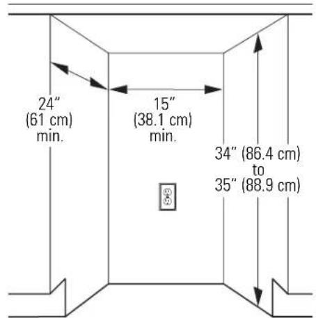
Locate the outlet 18^ (45.7 cm) min. from the floor, 3^ (7.6 cm) min. from either side
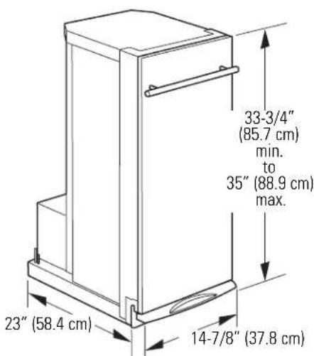
- Allow 23'' (58.4 cm) clearance at the front for a full drawer opening.
- Allow 6'' (15.2 cm) clearance on the right side to the nearest vertical wall or cabinet for bag removal.
Note: This compactor is designed for built-in applications only.
TOOLS REQUIRED
Level
-Phillips screwdriver

Pliers
All parts are located in a package inside the drawer. To order additional parts, call 800.626.2002 or visit GEAppliances.com in the United States. In Canada, call 1.800.561.3344 or visit www.GEApliances.ca.
Gloves

- Measuring tape
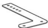
PARTS SUPPLIED
- 6 mounting screws, #8 x 11/16" (1.8 cm) long

- 2 side-mounting clips

- 2 countertop retaining brackets
Additional parts for ZCGS150SS and ZCGP150II
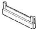
Door toekick
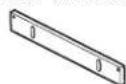
- Top toekick
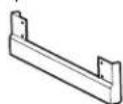
- Base toekick
- 8 Toekick screws, #8 × 5/16" (0.8 cm) long

4 White mounting screws, #8 x 11/16" (1.8 cm) long

CLEARANCES
- You should be able to fully open the compactor drawer. Six inches (15.2 cm) is required on the right side of the compactor for bag removal.
- Allow 23 inches (58.4 cm) in front of the compactor to remove the drawer.
- This compactor is designed as a built-in appliance only. It may be located in any convenient space under a countertop. DO NOT OPERATE FREE-STANDING.
- The compactor may be installed beneath countertops of stone or other materials that will not accept screws. No trim kit is required.
The compactor must be securely installed in a cabinet that is firmly attached to the house structure. Weight on the compactor drawer could cause the compactor to tip and result in injury. Never allow anyone to climb, sit or hang on the compactor drawer.
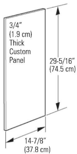
MODELS WITH A CUSTOM DRAWER PANEL
Models ZCGP150 II and GCG1700 II
The custom drawer panel and custom handle of your choice should be secured to the compactor before installation begins. A template with instructions and installation hardware is provided with those models. For planning purposes, you may order the template in advance by calling 1.800.GE.CARES (1.800.423.2737) or by visiting our website at GEAppliances.com in the United States. In Canada, call 1.800.561.3344 or visit www.GEApliances.ca. Order Pub. No. 31-30597. Complete panel installation instructions are included on the template.
CUSTOM PANEL SIZE REQUIREMENTS:
Maximum panel weight is 12 LBS (5.4kg)
ELECTRICAL REQUIREMENTS

WARNING!
FOR PERSONAL SAFETY: Remove house fuse or open circuit breaker before beginning installation. Do not use an extension cord or adapter plug with this appliance.
- The power supply cord and plug should be brought to a separate 15- or 20-ampere branch circuit single grounded receptacle. The outlet box should be located within reach of the 36^ (91.4 cm) power cord.
- This appliance must be supplied with 120V, 60Hz and connected to an individual properly grounded branch circuit, protected by a 15- or 20-ampere circuit breaker or time-delay fuse.
- If the electrical supply does not meet the above requirements, call a licensed electrician before proceeding.
IMPORTANT: Observe all governing codes and ordinances.
GROUNDING REQUIREMENTS

WARNING!
The improper connection of the equipment-grounding conductor can result in a risk of electric shock. Check with a qualified electrician or service representative if you are in doubt that the appliance is properly grounded.
- Electrical Ground is REQUIRED on this compactor.
DO NOT ground to a gas pipe. - DO NOT change the power supply cord plug. If it does not fit the outlet, have a proper outlet installed by a qualified electrician.
- DO NOT have a fuse in the neutral or grounding circuit. A fuse in the neutral or grounding circuit could result in an electrical shock.
DO NOT use an extension cord with this compactor.
Failure to follow these instructions could result in death or serious injury.
GROUNDING REQUIREMENTS (CONT.)
Grounding Instructions:
For your personal safety, this appliance must be grounded while in use to reduce the risk of electric shock. The appliance is equipped with a three-conductor power supply cord and a three-prong grounding-type plug to fit the proper grounding-type receptacle. The green (or green and yellow-colored) conductor in the cord is the grounding wire. Never connect the green (or green and yellow) wire to a live terminal.
This appliance is for use on a nominal 120-volt circuit and has a grounding attachment plug as shown in the figure below. Make sure that the appliance is connected to an outlet having the same configuration as the plug. No adapter should be used with this appliance.
3-prong grounding-type wall receptacle
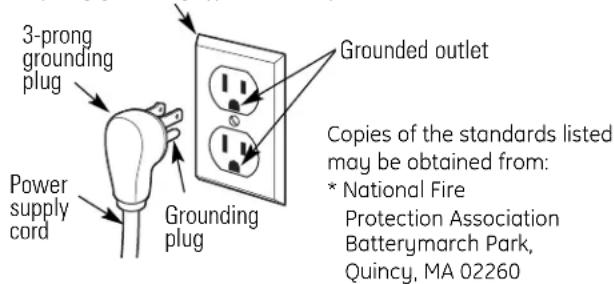
To minimize possible shock hazard, the cord must be plugged into the proper mating three-prong grounding-type wall receptacle, grounded in accordance with the National Electrical Code ANSI/NFPA70—latest edition* and all local codes and ordinances.
If a mating wall receptacle is not available, it is the personal responsibility and obligation of the customer to have a properly grounded three-prong wall receptacle installed by a qualified electrician.
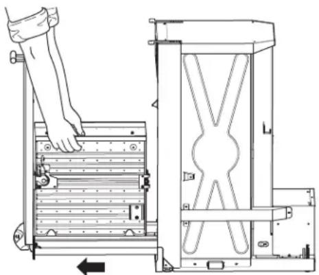
1 UNPACKING THE COMPACTOR
- Move the compactor close to the installation location.
- Use a section of the shipping carton to protect the finished floor.
- Do not use the handle to lift the compactor.
- Remove all protective packaging materials such as tape or shipping pads. Remove waxy residue caused by shipping material with a mild solution of liquid household cleaner and water.
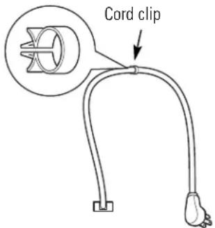
- Check that the power supply cord is attached to the cord clip on the rear of the compactor.
IMPORTANT: Use the shipping carton as a pad.
Do not slide the compactor across a finished floor.
Damage will occur.
- Open the compactor drawer and remove any shipping materials or other items shipped in the drawer.
- Do not remove the compactor bag (if installed).
- Grasp the sides of the drawer and lift it out of the compactor. Place the drawer on a protected surface. The drawer can scratch a finished floor.
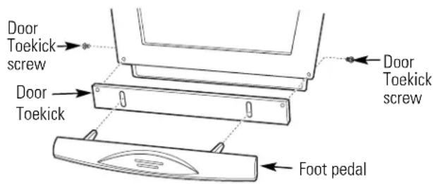
2 REPLACING THE DOOR TOEKICK (Optional for ZCGS150SS and ZCGP150II Models Only)
ZCGS150SS and ZCGP150II Models are supplied with extra toekicks that can replace the toekicks assembled on the compactor.
- Lay the drawer on its side.
- Remove 2 foot pedal screws on the side of the drawer. Lift off the foot pedal.
- Remove 2 door toekick screws. Remove door toekick.
- Install the new door toekick using the original screws.
- Reinstall the foot pedal using the original screws.
See Step 5 for instructions on replacing the top toekick and base toekick.
3 LEVELING THE COMPACTOR
- The top of the compactor should be at least 1/8'' (3 mm) from the top of the cabinet opening. You can adjust the height of the compactor by turning the screws on the front leveling legs and rear wheels.
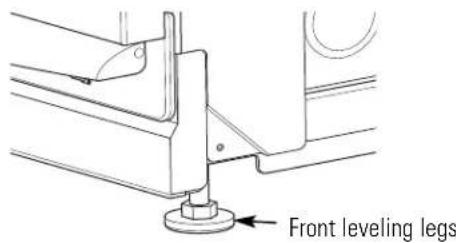
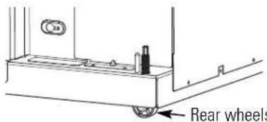
- Place a level inside the compactor on the floor of the cabinet.
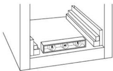
- Use the leveling legs to adjust level front to back and side to side.
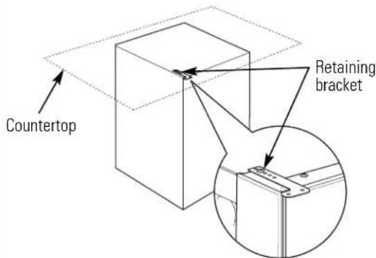
4 ADJUST THE RETAINING BRACKET
- Determine installation depth of the compactor beneath the countertop.
- Adjust the position of the retaining brackets so that the screws can meet the underside of the countertop.
- Mounting clips are provided for stone or other hard countertops that will not accept screws.
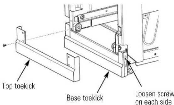
ADJUSTING THE BASE TOEKICK
A toekick extension is supplied. It can be used to cover any gaps from the bottom of the compactor to the floor. ZCGS150SS and ZCGP150II Models are also supplied with extra toekicks which can replace the original toekicks assembled on the compactor.
- Remove the top toekick screws as shown. Lift off top toekick piece.
- Loosen the base toekick screws, adjust to touch the floor and tighten the screws. If replacing the toekick, remove the screws and lift off the toekick. Install the new toekick with the original screws.
- Reinstall the top toekick piece with the original screws.
6 POSITION COMPACTOR UNDER THE COUNTERTOP
WARNING!
When moving the compactor, use gloves to protect and cushion your hands.
To protect the finished flooring, use a dolly to move the compactor near the installation location.
Failure to follow these instructions could result in injury.
- Plug the power cord into a properly grounded receptacle.
- Carefully lift the front of the compactor slightly and roll the unit into the cabinet opening.
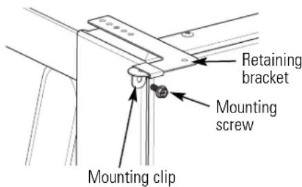
7 ATTACH THE COMPACTOR TO THE COUNTERTOP
- Use two # 8 × 11 / 16'' (1.8 cm) long mounting screws to fasten each retaining bracket at the top of the compactor to the underside of the countertop.
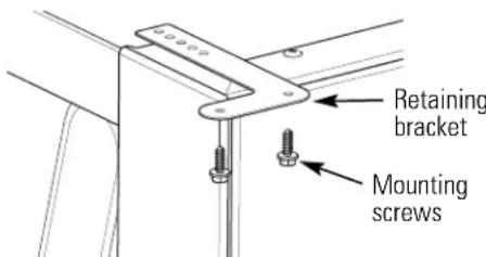
- If the brackets cannot be attached to the underside of the countertop, attach mounting clips to the bracket. Fasten the compactor to the cabinet front with mounting screws through the mounting clips.
Installation
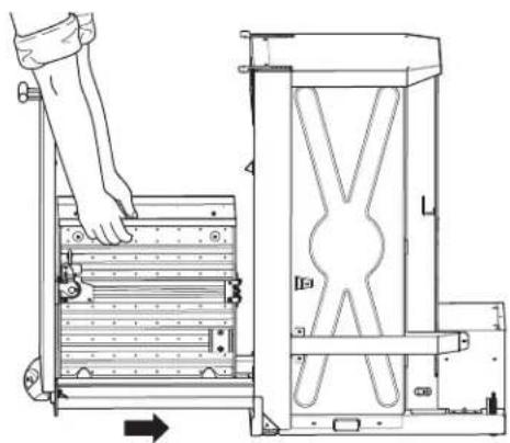
8 REINSTALL THE COMPACTOR DRAWER
- Grasp the sides of the drawer. Carefully slide the drawer into the compactor.
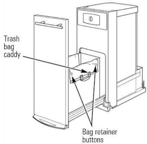
9 INSTALLATION OF THE TRASH BAG CADDY (on some models)
- Set the bag caddy into the drawer and hook the prepunched holes in the caddy on the bag retainer buttons.
- Set the trash bag into the bag caddy and fold over.
- Hook the holes in the bag over the bag retainer buttons.
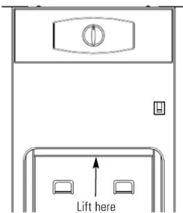
10 FINALIZE THE INSTALLATION
- Turn power on at the source.
- Turn the knob to ON.
- Make sure the drawer is fully closed.
- Lift the foot pedal to start the cycle.
The ram will travel downward, reverse and return to the starting position. - The compactor will shut off automatically.
The cycle should take less than 30 seconds.
Refer to your Owner's Manual for operating instructions.
NOTE: While performing installations described in this book, safety glasses or goggles should be worn.
NOTE: Product improvement is a continuing endeavor at General Electric. Therefore, materials, appearance and specifications are subject to change without notice.

GE Consumer & Industrial
Appliances
General Electric Company
Louisville, KY 40225
GEAppliances.com
Pub.No.31-30256-1 206C1559P196
09-09 JR
Printed in China
Instructions d-installation
Instructions d-installation
DIMENSIONS ET DÉGAGEMENTS DU PRODUIT
General Electric Company
Louisville, KY 40225
GEAppliances.com
Pub.No.31-30256-1
206C1559P196
09-09 JR
Imprimé en Chine