WFG 155 - Wine cellar VESTFROST - Free user manual and instructions
Find the device manual for free WFG 155 VESTFROST in PDF.
| Product type | Wine cellar |
| Brand | Vestfrost |
| Model | WFG 155 |
| Estimated capacity | 155 bottles |
| Power supply | 220-240 V / 50 Hz, protection 10-13 A |
| Climate class | SN, N, ST, T (ambient temperature from +10°C to +43°C) |
| Refrigerant | Flammable (type and quantity on rating plate) |
| Temperature zones | Dual zone: top (8-22°C) and bottom (5-22°C) |
| Control | Electronic with digital display |
| Child lock | Yes (key lock) |
| Alarms | Open door, high temperature (HtA) and low temperature (LtA) |
| Lighting | LED, permanent or timed (door) |
| Defrosting | Automatic |
| Charcoal filter | Yes, to neutralize odors |
| Lock | Yes (key included) |
| Adjustable feet | Yes |
| Door reversal | Possible by a technician |
| Cleaning | Warm water and mild dish soap, vacuum for condenser |
| Seal maintenance | Cleaning with clean water |
| After-sales service | Contact an approved professional |
| Warranty | According to manufacturer's conditions (except damage due to misuse) |
Frequently Asked Questions - WFG 155 VESTFROST
User questions about WFG 155 VESTFROST
0 question about this device. Answer the ones you know or ask your own.
Ask a new question about this device
Download the instructions for your Wine cellar in PDF format for free! Find your manual WFG 155 - VESTFROST and take your electronic device back in hand. On this page are published all the documents necessary for the use of your device. WFG 155 by VESTFROST.
USER MANUAL WFG 155 VESTFROST
natural_image
Exterior view of a modern stainless steel refrigerator with clear glass doors (no visible text or symbols)
WFG 185 / 155
GB Instructions for use
As the appliance contains a flammable refrigerant, it is essential to ensure that the refrigerant pipes are not damaged.
The quantity and type of the refrigerant used in your appliance is indicated on the rating plate.
Standard EN378 specifies that the room in which you install your appliance must have a volume of 1 m^3 per 8 g of hydrocarbon refrigerant used in the appliances. This is to avoid the formation of flammable gas/air mixtures in the room where the appliance is located in the event of a leak in the refrigerant circuit.
WARNING:
Keep ventilation openings in the appliance's cabinet or in the built-in structure clear of obstruction
WARNING:
Do not use other mechanical devices or other means to accelerate the defrosting process than those recommended by the manufacturer
WARNING:
Do not damage the refrigerant system
WARNING:
Do not use electrical appli- ances inside the refrigerated storage compartment, unless they are of a type recommended by the manufacturer
WARNING:
Do not expose the appliance to rain
WARNING:
This appliance is not intended for use by children and above and persons with reduced physical, sensory or mental capabilities or lack of experience and knowledge if they have been given supervision or instruction concerning use of the appliance in a safe way and understand the hazards involved
WARNING:
Children must not play with, on, or around the appliance.
WARNING:
Children must not clean the appliance or carry out general maintenance unless they are at least 8 years old and are being supervised.
WARNING:
Do not store explosives, such as aerosol cans with flammable propellants in the unit.
WARNING:
Danger risk of fire or explosion if flammable refrigerant are used. To be repaired only by trained personnel.
WARNING:
Cleaning and user maintenance shall not be made by children without supervision
WARNING:
Cleaning and user maintenance shall not be made by children without supervision
natural_image
Warning symbol of a flame inside a triangle (no text or numbers)WARNING:
When positioning the appliance, ensure the power cord is not trapped or damaged.
WARNING:
Do not locate multiple portable socket-outlets or portable power supplies at the rear of the appliance.
WARNING:
Danger risk of fire or explosion if flammable refrigerant are used. To be repaired only by trained personnel.
• Always keep the keys in a separate place and out of reach of children
- Before servicing or cleaning the appliance, unplug the appliance from the mains or disconnect the electrical power supply
- If the supply cord is damaged, it must be replaced by the manufacturer, its service agent, or similarly qualified persons in order to avoid a hazard
- Relevant for Australia: Supply cord fitted with a plug complies with AS/NZS 3112.
- Frost formation on the interior evaporator wall and upper parts is a natural phenomenon. Therefore, the appliance should be defrosted during normal cleaning or maintenance.
- Please note that changes to the appliance construction will cancel all warranty and product liability
- If the supply cord is damaged, it must be replaced by the manufacturer, its service agent, or similarly qualified persons inorder to avoid a hazard
- Do not use extension cords.
- This appliance is intended to be used exclusively for the storage of wine
CLASS 1 LED PRODUCT
Contents
Warning 2
Savings in energy consumption in the use....4
Before use ....5
Get to know your wine cooler 6
Electrical connection ....7
Installation and start-up 7
Installation 8
Operation and function 10
Defrosting, cleaning and maintenance .....12
Fault finding 13
Warranty, spare parts and service .....14
Disposal 15
CE Declaration of conformity......page A
Savings in energy consumption in the use
The energy consumption reduces ..
1)..the lower the ambient temperature is.
2)..the warmer thermostat set point is.
3)..the lower the number and the shorter the length of the door openings is.
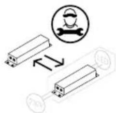
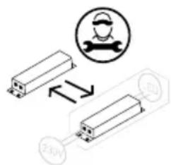
Replaceable light source by a professional
Replaceable control gear by a professional

Before use
On receipt, check to ensure that the appliance has not been damaged during transport. Transport damage should be reported to the local distributor before the wine cooler is put to use.
Remove the packaging. Clean the inside of the cabinet using warm water with a mild detergent. Rinse with clean water and dry thoroughly (see cleaning instructions). Use a soft cloth.
If during transport the appliance has been laid down, or if it has been stored in cold surroundings (colder than +5°C), it must be allowed to stabilise in an upright position for at least an hour before being switched on.
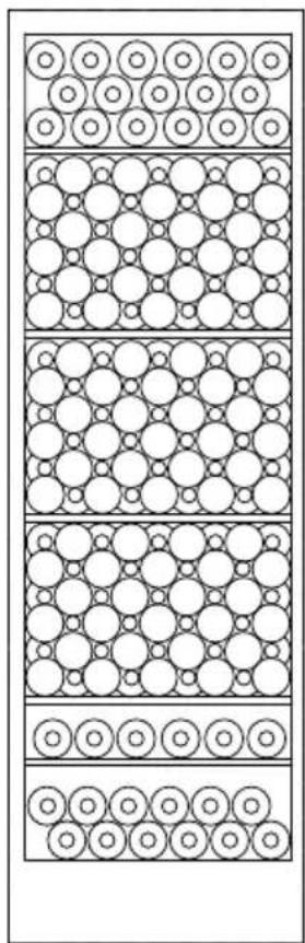
Get to know your wine cooler
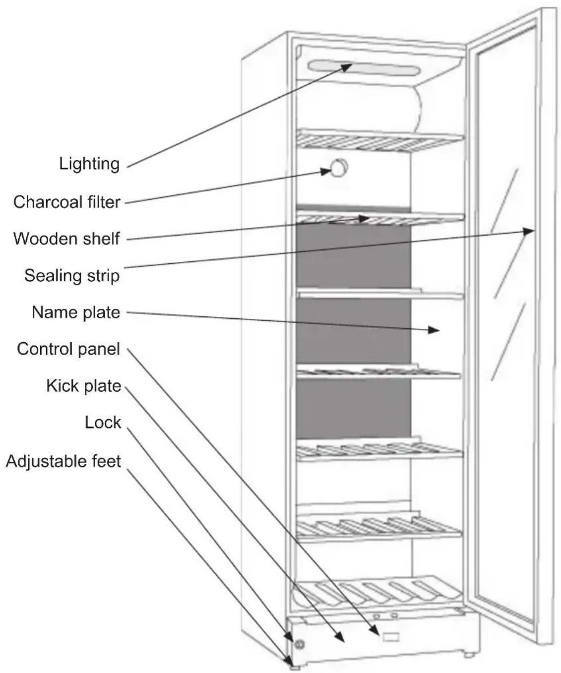
fig.1
Electrical connection
Wiring and connections in power supply systems must been all applicable (local and national) electrical codes. Consult these codes lengths and sizes prior to cabinet installation.
This device complies with relevant EU directives including Low Voltage Directive 2014/35/EU and Electromagnetic Compatibility Directive 2014/30/EU
The socket should be freely accessible.
Connect the appliance only to 220/240 V / 50Hz alternating current via a correctly installed earthed socket.
The socket must be fused with a 10-13 A fuse.
If the appliance is to be operated in a non-European country, check on the rating plate whether the indicated voltage and current type correspond to the values of your mains supply.
Information regarding voltage, current or power are given on the rating plate
The power cord may be replaced by a technician only.
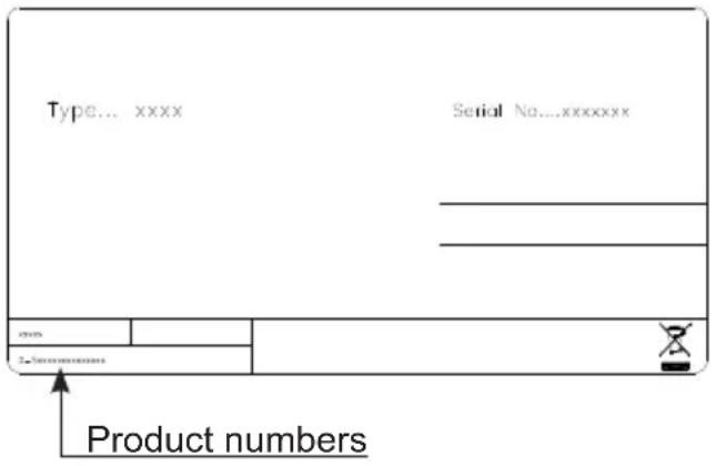
The rating plate provides various technical information as well as type and serial number.
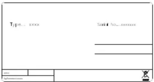
fig.2
Installation and start-up
Placement
For safety and operational reasons, the appliance must not be installed outdoors.
The appliance should be placed on a level surface in a dry, well ventilated room (max. 75% relative air humidity). Never place the appliance close to sources of heat such as cookers or radiators, and avoid placing it in direct sunlight.
Ambient temperature
The climate class is stated on the name plate. This specifies the optimum ambient temperature. Wine coolers with winter position, however, function at ambient temperatures as low as 5^ C.
| Climate class Optimum room temperature | |
| SN +10 °C to +32 °C | |
| N +16 °C to +32 °C | |
| ST +18 °C to +38 °C | |
| T +18 °C to +43 °C |
Installation
The surface on which the appliance is to be placed must be level. Do not use a frame or similar.
The appliance can be installed as a free-standing unit against a wall, built into a closet or lined up with other appliances.
It is important that the appliance be well ventilated and that air can circulate unhindered above, below and around it.
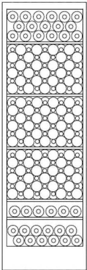
The figures below illustrate how the necessary air circulation around the appliance can be ensured (figs 3).
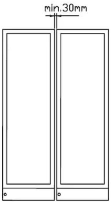
fig. 4
(fig 4) A "Side by Side" kit can be ordered
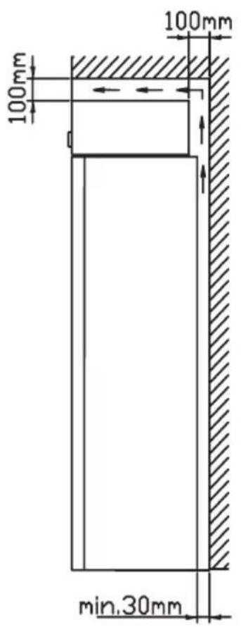
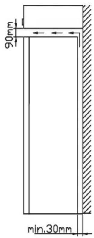

fig. 3 fig. 5
The distance pieces on the rear of the appliance ensure sufficient air circulation. Fit the two caps supplied with the appliance as shown in fig.6.
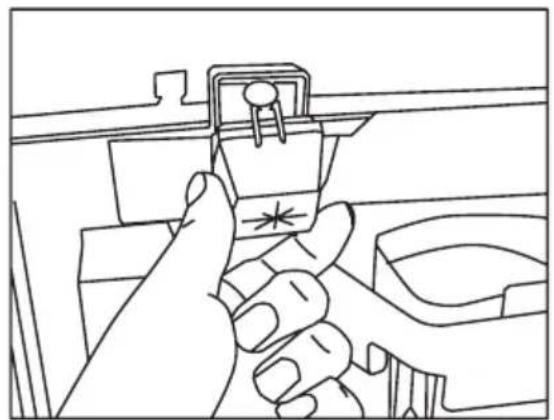
natural_image
Line drawing of a hand inserting a plastic clip into a box (no text or symbols)fig. 6
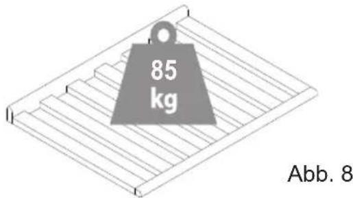
Max. 85 kg.
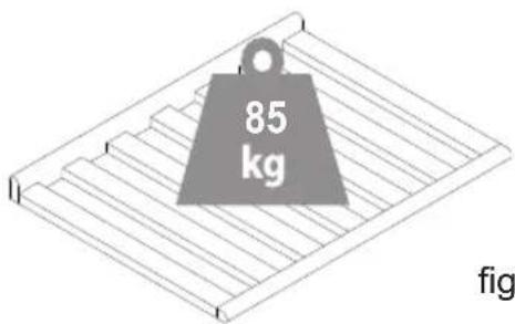
fig. 8
Setting up
It is important that the appliance be absolutely level. It can be levelled by screwing the adjustable feet at the front of the appliance up or down (fig 7). Use a spirit level to check that the appliance is absolutely level sideways.
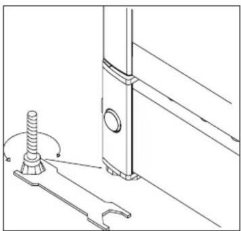
natural_image
Technical line drawing of a mechanical assembly with a screw and wrench (no text or symbols)fig. 7
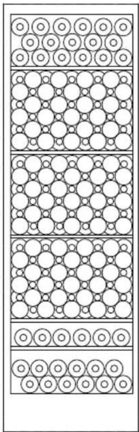
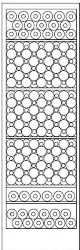
natural_image
Diagram of layered circular arrangements with no text or symbols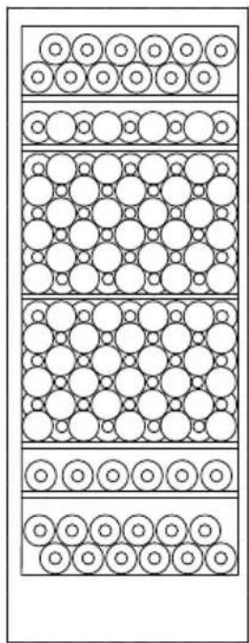
natural_image
Diagram of layered circular structures with uniform spacing, no text or symbols presentfig. 9
Operation and function
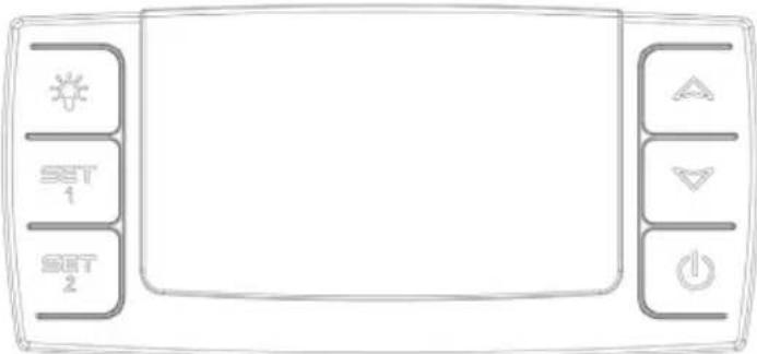
fig. 10
Electronic control
The electronic control ensures that the temperatures set at the top and at the bottom of the appliance are maintained. This is achieved by means of an advanced control of the refrigeration system, the heating element, and the fan. The set temperature will be stored in the event of power failure.
The electronic control has the following functions:
- On/off switch
- Light switch*
- Temperature setting
• Temperature indication - Alarm for too high and too low temperatures
- Door alarm
* The light may either be turned on constantly or only when the door is open.
Temperature indication
The display shows the actual temperature. The upper digits of the display indicate the temperature at the top of the appliance, and the lower digits of the display indicate the temperature at the bottom of the appliance. The temperature indicator is equipped with
a built-in filter which simulates the actual temperature in the bottles. Consequently, the indicator does not react on short-term fluctuations of the air temperature
Temperature setting
The thermostat is equipped with a child lock device. This device is activated by pushing the “up and down” buttons simultaneously. After approx. 3 seconds “Pof” flashes in the display. Then the actual temperatures are shown as usual. In addition, the set temperatures can be shown by pushing SET1 and SET2, respectively.
The child lock device is cancelled by pushing the "up and down" buttons simultaneously. After approx. 3 seconds "Pon" flashes in the display, and the temperature can be set.
Temperature setting at the top of the appliance
Push SET1. Then the temperature at the top of the appliance can be adjusted up and down by means of the "up and down" buttons. The temperature can be adjusted from 8 to 22°C, however so that the temperature cannot be set at a lower temperature than the actual set point for the bottom temperature sensor.
Temperature setting at the bot- tom of the appliance
Push SET2. Then the temperature at the bottom of the appliance can be adjusted up and down by means of the “up and down” buttons. The temperature can be adjusted from 5 to 22°C, however so that the temperature cannot be set at a higher temperature than the actual set point for the upper temperature sensor.
Alarm devices
There is a sub-alarm for the low-temperature sensor and an excess-alarm for the high-temperature sensor.
The alarm consists of a beeper and a warning on the display.
Alarm for high temperature: beep sound + alternating display of "HtA" and actual temperature
Alarm for low temperature: beep sound + alternating display of “LtA” and actual temperature
The alarm temperature depends on the set points.
The beep sound can be cancelled by pushing a random thermostat button. Push the on/off button to erase the display alarm, first for cancelling the alarm, then again for restarting the compressor.
Door alarm
When the door has been open for more than 2 minutes the door alarm is activated.
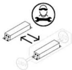
Possible door turn
It is recommended that you use a technician for reversing the swing of your refrigerator door.
Permanent lighting
For presentation purposes of your wine, you can turn on the lights permanently. Please press the light switch image twice. If the controller is placed inside the cabinet press twice, if the controller is placed in the kick plate only press once. To switch off the permanent light press on again.
The light will always be on when the door is open.
Two-zone setting for serving temperature
Typical serving temperature settings for the top and bottom sections are 16^ C and 6^ C respectively. With these settings, a suitable temperature gradient will be achieved in the cabinet for the storage of various types of wine distributed from top to bottom as follows:
- heavy red wines +16 to +19°C
- rosé and light red wines +12 to +16°C
- white wines +10 to +12°C
- champagne and sparkling wines +6 to +8°C
It is recommended that wine be served at a temperature which is a couple of degrees lower than the desired drinking temperature as the wine will be warmed slightly when it is poured into the glass.
Single-zone setting for long-term storage
For long-term wine storage, the top and bottom sections should both be set at 12^ C. With identical settings for the top and bottom sections, the controls will maintain an even temperature throughout the cabinet.
However, the temperature in the room will gradually affect the temperature in the
cabinet through its door and sides, creating a slight temperature gradient from top to bottom. The controls will maintain the set temperature at the bottom of the cabinet, and any deviation from the setting will therefore occur at the top.
The difference will vary from 0 to 3°C, depending on the ambient temperature.
The frost protection thermostat
The appliance has a frost protection thermostat that take over control and run the appliance in safety mode in case of malfunction. In safety mode the cabinet will contain temperature between 2^ C – 4^ C.
Defrosting, cleaning and maintenance
Automatic defrosting
The wine cooler is defrosted automatically. Defrost water runs through a pipe and is collected in a tray above the compressor where the heat generated by the compressor causes it to evaporate. The defrost water tray should be cleaned at intervals.
Cleaning
Before cleaning the appliance, unplug it from the main supply. The cabinet is best cleaned using warm water (max. 65°C) with a little mild detergent. Never use cleaning agents that scour. Use a soft cloth. Rinse with clean water and dry thoroughly. The defrost water channel, in which condensation from the evaporator runs, is located at the bottom of the rear inside wall of the cabinet and must be kept clean. Add a few drops of disinfectant, e.g. Rodalon, to the defrost water drain a couple of times a year, and clean the drain using a pipe cleaner or similar. Never use sharp or pointed implements.
The sealing strip around the door must be cleaned regularly to prevent discolouration and prolong service life. Use clean water. After cleaning the sealing strip, check that it continues to provide a tight seal.
Dust collecting on the condenser on the rear of the cabinet, the compressor and in the compressor compartment is best removed using a vacuum cleaner.
Fault finding
| Fault Possible cause | Remedy | |
| The appliance is not working. | The appliance is switched off.Power failure; the fuse is blown; the appliance is not plugged in correctly. | Press the on/off switch.Check that power is connected.Reset the fuse. |
| Water collects in the bottom of the cabinet. | The defrost water pipe is blocked. | Clean the defrost water channel and the drain hole on the rear wall of the cabinet. |
| Vibration or bothersome noise. | The appliance is not level.The appliance is resting against other kitchen elements.Containers or bottles inside the cabinet are rattling against one another. | Level the appliance using a spirit level.Move the appliance away from the kitchen elements or appliances it is in contact with.Move containers and/or bottles apart. |
| Compressor runs continuously. | High room temperature. Ensure adequate ventilation. | |
| P1 is shown on the display. | The upper sensor is disconnected or short-circuited. | Call for service. The temperature within the entire cabinet is maintained at the higher of the two setpoints until the fault has been corrected. |
| P2 is shown on the display. | The lower sensor is disconnected or short-circuited. | Call for service. The temperature within the entire cabinet is maintained at the higher of the two setpoints until the fault has been corrected. |
| The appliance is too cold. | The appliance runs in safety mode. | Call for service. |
Warranty, spare parts and service
Warranty disclaimer
Faults and damage caused directly or indirectly by incorrect operation, misuse, insufficient maintenance, incorrect building, installation or mains connection. Fire, accident, lightening, voltage variation or other electrical interference, including defective fuses or faults in mains installations.
Repairs performed by others than approved service centres and any other faults and damage that the manufacturer can substantiate are caused by reasons other than manufacturing or material faults are not covered by the warranty.
Please note that changes to the construction of the appliance or changes to the component equipment of the appliance will invalidate warranty and product liability, and the appliance cannot be used lawfully. The approval stated on rating plate will also be invalidated.
Transport damage discovered by the buyer is primarily a matter to be settled between the buyer and the distributor, i.e. the distributor must ensure that such complaints are resolved to the buyer's satisfaction.
Before calling for technical assistance, please check whether you are able to rectify the fault yourself. If your request for assistance is unwarranted, e.g. if the appliance has failed as a result of a blown fuse or incorrect operation, you will be charged the costs incurred by your call for technical assistance.
Spare parts
When ordering spare parts, please state the type, serial and product numbers of your appliance. This information is given on the rating plate. The rating plate contains various technical information, including type and serial numbers.
Disposal
Information for Users on Collection and Disposal of Old Equipment and used Batteries
These symbols on the products, packaging, and/or accompanying documents mean that used electrical and electronic products and batteries should not be mixed with general household waste. For proper treatment, recovery and recycling of old products and used batteries, please take them to applicable collection points, in accordance with your national legislation and the Directives 2012/19/EU and 2006/66/EC.
By disposing of these products and batteries correctly, you will help to save valuable resources and prevent any potential negative effects on human health and the environment which could otherwise arise from inappropriate waste handling.
For more information about collection and recycling of old products and batteries, please contact your local municipality, your waste disposal service or the point of sale where you purchased the items.
Penalties may be applicable for incorrect disposal of this waste, in accordance with national legislation.
For business users in the European Union.
If you wish to discard electrical and electronic equipment, please contact your dealer or supplier for further information.
[Information on Disposal in other Countries outside the European Union]
These symbols are only valid in the European Union. If you wish to discard this product, please contact your local authorities or dealer and ask for the correct method of disposal.
Note for the battery symbol:
This symbol might be used in combination with a chemical symbol. In this case it complies with the requirement set by the Directive for the chemical involved.
Warnung
WARNUNG:
Vor dem Gebrauch
Belüftung
natural_image
Line drawing of a hand inserting a plastic clip into a box (no text or symbols)Abb 6
Max. 85 kg.
Aufstellung
natural_image
Technical line drawing of a mechanical assembly with a screw and wrench, no text or symbols presentAbb. 7
natural_image
Diagram of layered circular arrangements with concentric circles and horizontal lines, no text or symbols present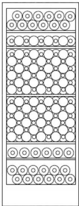
natural_image
Diagram of layered circular structures with uniform spacing, no text or symbols presentAbb. 9
Abb. 10
ADVARSEL:
Inden brug
fig. 3 fig. 5
(fig 4)
Et "Side by Side" kit kan bestilles.

natural_image
Line drawing of hands installing a component with a star symbol (no text or symbols present)Max. 85 kg.
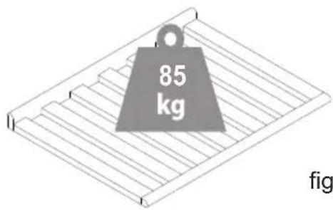
fig. 8
Opstilling
natural_image
Technical line drawing of a mechanical assembly with a bolt and bracket (no text or symbols)fig. 7
natural_image
Diagram of layered circular arrangements with no text or symbols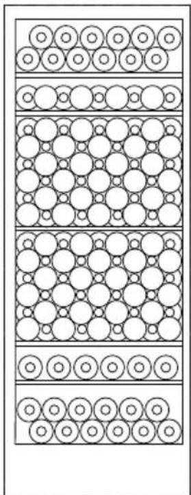
natural_image
Diagram of layered circular structures with uniform spacing, no text or symbols presentfig. 9
fig. 10
Elektronisk styring.
Temperatur-indstilling.
AVERTISSEMENT:
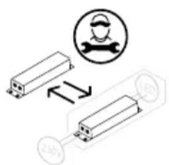
fig. 2

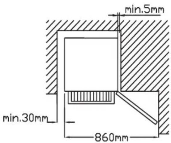
fig. 4
natural_image
Line drawing of a hand inserting a plastic clip into a door panel (no text or symbols)fig. 5
Max. 85 kg.
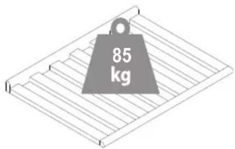
Fig. 7
Mise en place
natural_image
Technical line drawing of a mechanical assembly with a screw and base, showing motion indicators (no text or symbols)fig. 6
natural_image
Diagram of layered circular arrangements with alternating circles and dots, no text or symbols present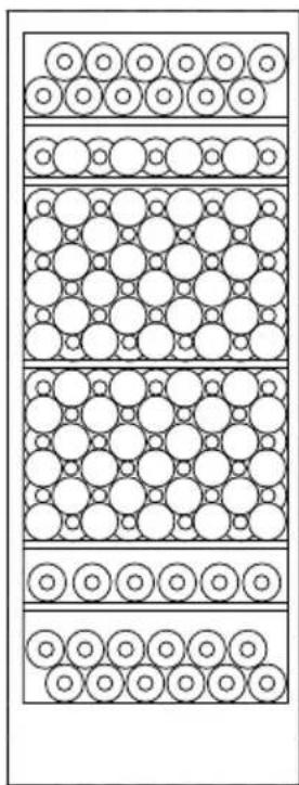
natural_image
Diagram of layered circular structures with uniform spacing, no text or symbols presentfig. 8
fig. 9
AATTENZIONE:
Dati tecnici
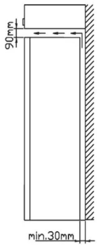
fig. 2 fig. 4
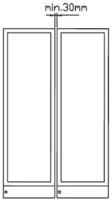
fig. 3
natural_image
Line drawing of a hand inserting a plastic clip into a box (no text or symbols)fig. 5
Max. 85 kg.
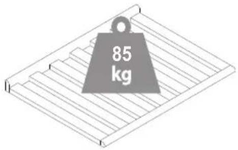
Fig. 7
natural_image
Technical line drawing of a mechanical assembly with a bolt and clamp (no text or symbols)fig. 6
natural_image
Diagram of layered circular arrangements with no text or symbols
natural_image
Diagram of layered circular structures with uniform spacing, no text or symbols presentfig. 8
fig. 9
Made in Denmark by A/S Vestfrost
The undersigned declare that the product is in conformity with the relevant statutory requirements and the applicable parts of harmonized European standards:
Low Voltage Directive 2014/35/EU
EN 60335-1:2012+A11+A13+A1+A14+A2
EN 60335-2-24:2010+A1+A2+A11
EN 62233:2008
Electromagnetic Compatibility Directive 2014/30/EU
EN 61000-3-3: 2013
EN 61000-3-2: 2014
EN 55014-1: 2017+A11
EN 55014-2: 1997+A1+A2+AC
Ecodesign Directive 2009/125/EC
Eco design of household refrigerating appliances 2019/2019
Restriction of Hazardous Substances Directive (RoHS) 2011/65/EU
A/S VESTFROST
2021.10.19
Appliance Certification Manager
Jørgen Dyrholm
name
Esbjerg Denmark
VESTFROST
SOLUTIONS
A/S Vestfrost
Falkevej 12
DK-6705 Esbjerg ∅, Denmark
Tel.: +45 79 14 22 22 · Fax: +45 79 14 23 65
Jergen Dyrbolou signature
Esbjerg Denmark
GB Reserving the right to alter specifications without prior notice.