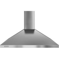
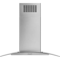
WVW53UC0LS - Basket WHIRLPOOL - Free user manual and instructions
Find the device manual for free WVW53UC0LS WHIRLPOOL in PDF.
Download the instructions for your Basket in PDF format for free! Find your manual WVW53UC0LS - WHIRLPOOL and take your electronic device back in hand. On this page are published all the documents necessary for the use of your device. WVW53UC0LS by WHIRLPOOL.
USER MANUAL WVW53UC0LS WHIRLPOOL
Installation Instructions and Use & Care Guide For questions about features, operation/performance, parts, accessories or service, call: 1-800-253-1301 or visit our website at www.whirlpool.com In Canada, call 1-800-807-6777 or visit our website at www.whirlpool.ca
IMPORTANT: READ AND SAVE THESE INSTRUCTIONS.
You can be killed or seriously injured if you don't immediately You can be killed or seriously injured if you don't follow All safety messages will tell you what the potential hazard is, tell you how to reduce the chance of injury, and tell you what can happen if the instructions are not followed. Your safety and the safety of others are very important. We have provided many important safety messages in this manual and on your appliance. Always read and obey all safety messages. This is the safety alert symbol. This symbol alerts you to potential hazards that can kill or hurt you and others. All safety messages will follow the safety alert symbol and either the word “DANGER” or “WARNING.” These words mean: follow instructions. instructions. DANGER WARNING State of California Proposition 65 Warnings:
WARNING: This product contains one or more chemicals known to the State of California to cause cancer.
WARNING: This product contains one or more chemicals known to the State of California to cause birth defects or other
READ AND SAVE THESE INSTRUCTIONS4
INSTALLATION REQUIREMENTS Tools and Parts Gather the required tools and parts before starting installation.Read and follow the instructions provided withanytools listed here. Tools Needed ■ Level ■ Drill with 1
" (4.8mm) drillbits ■ Pencil ■ Wire stripper or utility knife ■ Tape measure or ruler ■ Pliers ■ Caulking gun and weatherproof caulking compound ■ Vent clamps ■ Jigsaw or keyhole saw ■ Flat-blade screwdriver ■ Metal snips ■ Phillips screwdriver ■ T20
" (12.7 mm) UL listed or CSA approved strain relief ■ 3 UL listed wire connectors For Vented Installations, You Will Also Need: ■ 1 wall or roof cap ■ Metal vent system For Non-Vented (Recirculating) Installations, YouWillAlsoNeed: ■ Recirculation Kit for non-vented (recirculating) installations only. See “Assistance or Service” section to order. ■ 6" (15.2 cm) diameter round metal vent duct - lengthrequiredis determined by ceiling height. Parts Supplied Remove parts from packages. Check that all parts are included. ■ Hood canopy assembly with blower and LED lights installed ■ Vent transition with back draft dampers installed ■ Vent cover support bracket ■ Metal grease lter(s) ■ Mounting template ■ 2-piece vent cover ■ 2 - 2.9 x 6.5 mm screws (Phillips) ■ 2 - 3.5 x 9.5 mm screws (Phillips) ■ 6 - 5 x 45 mm mounting screws (#2 Phillips) ■ 4 - 8 x 40 mm wall anchors (masonry)
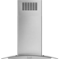
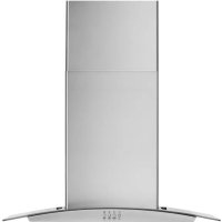
†TORX and T20 are registered trademarks of Acument Intellectual Properties, LLC. Location Requirements IMPORTANT: Observe all governing codes and ordinances. Have a qualied technician install the range hood. It is the installer’s responsibility to comply with installation clearances specied on the model/serial/rating plate. The model/serial/ rating plate is located behind the left lter on the rear wall ofthevent hood. Canopy hood location should be away from strong draft areas, such as windows, doors, and strong heating vents. Cabinet opening dimensions that are shown must be used. Given dimensions provide minimum clearance. This range hood is recommended for use with cooktops with amaximum total rating of 60,000 BTUs or less. Grounded electrical outlet is required. See “Electrical Requirements” section. The canopy hood is factory set for venting through the roof or wall. For non-vented (recirculating) installation, see “For non- vented (recirculating) installation only” in the “Connect Vent System” section. Recirculation Kit isavailable from your dealer or an authorized parts distributor. See “Assistance or Service” section to order. All openings in ceiling and wall where canopy hood will be installed must be sealed. For Mobile Home Installations The installation of this range hood must conform to the Manufactured Home Construction Safety Standards, Title 24CFR, Part 328 (formerly the Federal Standard for Mobile Home Construction and Safety, Title 24, HUD, Part 280) or whensuch standard is not applicable, the standard for Manufactured Home Installation 1982 (Manufactured Home Sites, Communities and Setups) ANSI A225.1/NFPA 501A, orlatest edition, or with local codes. Product Dimensions
"(26 cm)30" (76 cm)36" (91.2 cm)
"(34 cm) “X” bottom of canopy to cooking surface15" (38.1 cm) IMPORTANT: Minimum distance “X”: 24" (61 cm) fromelectriccookingsurface Minimum distance “X”: 27" (68.6 cm) fromgascookingsurface Suggested maximum distance “X”: 36" (91.4 cm) The chimneys can be adjusted for different ceiling heights. Seethe following chart. Vented Installations Min. ceiling height Max. ceiling height Electric cooking surface 7' 5" (2.26 m) 9' 2" (2.79 m) Gas cooking surface 7' 8" (2.34 m) 9' 2" (2.79 m) Non-Vented (Recirculating) Installations Min. ceiling height Max. ceiling height Electric cooking surface 7' 5" (2.26 m) 9' 6" (2.9 m) Gas cooking surface 7' 8" (2.34 m) 9' 6" (2.9 m) NOTE: The range hood chimneys are adjustable and designed tomeet varying ceiling or soft heights, depending on the distance “X” between the bottom of the range hood and the cooking surface. For higher ceilings, a Stainless Steel Chimney Extension Kit is available from your dealer or an authorized parts distributor. See “Assistance or Service” section to order. The chimney extension replaces the upper chimney shipped with the range hood. Venting Requirements (vented models only) ■ Vent system must terminate to the outdoors except for non-vented (recirculating) installations. ■ Do not terminate the vent system in an attic or other enclosed area. ■ Do not use 4" (10.2 cm) laundry-type wall cap. ■ Use metal vent only. Rigid metal vent is recommended. Plastic or metal foil vent is not recommended. ■ The length of vent system and number of elbows should bekept to a minimum to provide efcient performance. For the Most Efcient and Quiet Operation: ■ Use no more than three 90° elbows. ■ Make sure there is a minimum of 24" (61 cm) of straight ventbetween the elbows if more than 1 elbow is used. ■ Do not install 2 elbows together. ■ Use clamps to seal all joints in the vent system. ■ The vent system must have a damper. If the roof orwallcaphas a damper, do not use the damper suppliedwith therange hood. ■ Use caulking to seal exterior wall or roof opening aroundthecap. ■ The size of the vent should be uniform. Cold Weather Installations An additional back draft damper should be installed to minimize backward cold air ow and a thermal break should be installed to minimize conduction of outside temperatures as part of the vent system. The damper should be on the cold air side of the thermal break. The break should be as close as possible to where the vent system enters the heated portion of the house. Makeup Air Local building codes may require the use of makeup air systems when using ventilation systems greater than specied CFM of air movement. The specied CFM varies from locale to locale. Consult your HVAC professional for specic requirements in yourarea. Venting Methods This canopy hood is factory set for venting through the roof orwall. A 6" (15.2 cm) round vent system is needed for installation (notincluded). The hood exhaust opening is 6" (15.2 cm) round. NOTE: Flexible vent is not recommended. Flexible vent creates back pressure and air turbulence that greatly reduceperformance. Vent system can terminate either through the roof or wall. Tovent through a wall, a 90° elbow is needed. Rear Discharge A 90° elbow may be installed immediately above the hood.6 For Non-Vented (Recirculating) Installations If it is not possible to vent cooking fumes and vapors to the outside, the hood can be used in the non-vented (recirculating) version, tting a charcoal lter and the deector. Fumes and vapors are recycled through the top grille. See the “Assistance or Service” section for information on ordering. Calculating Vent System Length To calculate the length of the system you need, add the equivalent feet (meters) for each vent piece used in the system. Vent Piece 6" (15.2 cm) Round 45° elbow 2.5 ft (0.8 m) 90° elbow 5 ft (1.5 m) Maximum equivalent vent length is 35 ft (10.7 m). Example Vent System The following example falls within the maximum recommendedvent length of 35 ft (10.7 m).
8 ft (2.4 m) straight = 8 ft (2.4 m) Length of system = 13 ft (3.9 m) Electrical Requirements Observe all governing codes and ordinances. Ensure that the electrical installation is adequate and in conformance with National Electrical Code, ANSI/NFPA 70(latest edition) or CSA Standards C22.1-94, Canadian Electrical Code, Part 1 and C22.2 No. 0-M91 (latest edition), andall local codes and ordinances. If codes permit and a separate ground wire is used, it is recommended that a qualied electrician determine that theground path is adequate. A copy of the above code standards can be obtained from: National Fire Protection Association 1 Batterymarch Park Quincy, MA 02169-7471 CSA International 8501 East Pleasant Valley Road Cleveland, OH 44131-5575 ■ A 120 volt, 60 Hz., AC only, 15-amp, fused electrical circuitisrequired. ■ If the house has aluminum wiring, follow the procedurebelow: Connect the aluminum wiring using special connectors and/or tools designed and UL listed for joining copper to aluminum. Follow the electrical connector manufacturer’s recommended procedure. Aluminum/copper connection must conform with local codes and industry accepted wiring practices. ■ Wire sizes and connections must conform with the rating of the appliance as specied on the model/serial/rating plate. The model/serial/rating plate is located behind the left lter on the rear wall of the range hood. ■ Wire sizes must conform to the requirements of the National Electrical Code, ANSI/NFPA 70 (latest edition), or CSA Standards C22. 1-94, Canadian Electrical Code, Part 1 andC22.2 No. 0-M91 (latest edition) and all local codes andordinances. Non-Vented (Recirculating) Wall Venting Roof Venting
6 ft (1.8 m) 2 ft (0.6 m) Wall cap7 INSTALLATION INSTRUCTIONS Prepare Location ■ It is recommended that the vent system be installed beforehood is installed. ■ Before making cutouts, make sure there is proper clearancewithin the ceiling or wall for exhaust vent. ■ Check your ceiling height and the hood height maximumbefore you select your hood.
1. Disconnect power.
2. Determine which venting method to use: roof, wall,
3. Select a at surface for assembling the range hood.
Placecovering over that surface.
4. Using 2 or more people, lift range hood onto
5. Remove wood base from range hood and dispose
ofproperly. Range Hood Mounting Screws Installation
1. Determine and mark the centerline on the wall where
thecanopy hood will be installed.
2. Select a mounting height between a minimum of 24" (61cm)
for an electric cooking surface, a minimum of 27" (68.6 cm) for a gas cooking surface, and a suggested maximum of 36" (91.4 cm) above the range to the bottom ofthe hood. Mark a reference line on the wall.
3. Tape template in place, aligning the template centerline
andbottom of template with hood bottom line and with thecenterline marked on the wall.
4. Mark centers of the fastener locations through the template
to the wall. IMPORTANT: All canopy mounting screws must be installed into wood where possible. If there is no wood to screw into, additional wall framing supports may be required or use (4) 10 x 60 mm wall anchors and 5.4 x 75 mm screws (not included). Remove the template.
" (4.8 mm) pilot holes at all locations wherescrews are being installed into wood. For wall anchors, drill
" (10 mm) holes at all locations where wall anchors are being used.
6. For wood, install (2) 5 x 45 mm mounting screws. Leave
" (6.4 mm) gap between the wall and the back of the screw head to slide range hood into place. For wall anchors, install the 10 x 60 mm wall anchors andinstall the 5.4 x 75 mm screws into the wall anchors. Tighten until the wall anchors are secure. Back the screws out
" (6.4 mm). Vent Cover Support Bracket Installation Installations using telescoping upper and lower vent coverassembly
1. Position vent cover bracket on wall about
" (3 mm) awayfrom the ceiling.
2. Mark the hole locations.
" (9.5 mm) holes for 8 x 40 mm wall anchors andinsert anchors ush with the wall.
4. Attach vent cover support bracket to wall.
Complete Preparation
1. Determine and make all necessary cuts in the wall for the
vent system. Install the vent system before installing the hood. See “Venting Requirements” section.
2. Determine the required height for the home power supply
" (3.2 cm) hole at this location.
3. Run the home power supply cable according to the National
Electrical Code or CSA Standards and local codes and ordinances. There must be enough
" conduit and wires from the fused disconnect (or circuit breaker) box to make the connection in the hood’s electrical terminal box. NOTE: Do not reconnect power until installation is complete.
4. Use caulk to seal all openings.
WARNING Excessive Weight Hazard Use two or more people to move and install range hood. Failure to do so can result in back or other injury. Vertical Centerline
A. 8 x 40 mm wall anchors B. Centerline on wall C. Vent cover support bracket D. 5 x 45 mm screws8 Connect Vent System
1. Install transition on top of hood (if removed for shipping)
with(2) 3.5 x 9.5 mm sheet metal screws. For vented installations only:
1. Fit vent system over transition piece.
2. Seal connection with clamps.
3. Check that back draft dampers work properly.
Install Range Hood NOTE: Remove protective lm from range hood and metal lters.
1. Using 2 or more people, hang range hood on 2 mounting
screws through the mounting slots on back of hood.
2. Remove the grease lter. See “Range Hood Care” section.
3. Level the range hood and tighten upper mounting screws.
4. Install (2) 5 x 45 mm lower mounting screws and tighten.
Usethe optional wall anchors if needed. For non-vented (recirculating) installation only:
1. Assemble the air deector with the duct cover bracket with
2assembly screws provided with the Recirculation Kit.
2. Measure from the bottom of the air deector to the bottom
3. Cut the duct to the measured size “X.”
4. Remove the air deector.
5. Slide the duct onto the bottom of the air deector.
6. Place the assembled air deector and duct over
theexhaustoutlet from the hood.
7. Reassemble the air deector to the duct cover bracket
withthe 2 assembly screws.
8. Seal connections with vent clamps.
A. Vent transition B. 3.5 x 9.5 mm screw
A. Mounting screws B. Mounting slots C. Lower mounting screws
A. Vent cover bracket B. Assembly screws C. Deector
A. Air deector B. Vent clamp C. X = length to cut vent duct D. Vent duct E. Exhaust outlet9 Make Electrical Connection
1. Disconnect power.
2. Remove terminal box cover.
3. Remove the knockout in the terminal box and install
4. Run home power supply cable through strain relief
5. Use UL listed wire connectors and connect
blackwires(E)together.
6. Use UL listed wire connectors and connect
whitewires(C)together.
7. Connect green (or bare) ground wire from home power
supply to yellow-green ground wire (F) in terminal box usingUL listed wire connectors.
8. Tighten strain relief screw.
9. Install terminal box cover.
10. Check that all light bulbs are secure in their sockets.
11. Reconnect power.
Install Vent Covers NOTE: Remove protective lm from the vent covers.
1. When using both upper and lower vent covers, push lower
coverdown onto hood and lift upper cover to ceiling and installwith (2) 2.9 x 6.5 mm screws. NOTE: For vented installations, the upper vent cover maybereversed to hide slots.
A. Home power supply cableB. UL listed or CSA approvedstrain reliefC. UL listed wire connectorsD. White wiresE. Black wiresF. Green (or bare) and yellow-green ground wiresG. Terminal box WARNING Electrical Shock Hazard Electrically ground blower. Connect ground wire to green and yellow ground wire in terminal box. Failure to do so can result in death or electrical shock.
A. Upper vent coverB. Lower vent coverC. 2.9 x 6.5 mm screwsD. Bracket WARNING Electrical Shock Hazard Disconnect power before servicing. Replace all parts and panels before operating. Failure to do so can result in death or electrical shock.10 Complete Installation
1. For non-vented (recirculating) installations only, install
charcoal lters over the grease lters, using the clips provided in the kit. See the “Range Hood Care” section.
2. Install metal lters. See the “Range Hood Care” section.
3. Check the operation of the range hood blower and light.
Seethe “Range Hood Use” section. NOTE: To get the most efcient use from your new range hood,read the “Range Hood Use” section.
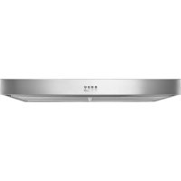
The range hood is designed to remove smoke, cooking vapors,and odors from the cooktop area. For best results, startthe hood before cooking and allow it to operate several minutes after the cooking is complete to clear all smoke and odors from the kitchen. The hood controls are located on the front side of the canopy. Range Hood Controls A. Light button B. Blower ON/OFF and minimum speed button C. Blower speed medium button D. Blower speed maximum button A B C D Operating the light The button controls both lights. Press once forONand again for OFF. Operating the blower The ON/OFF button turn the blower on and set the blower minimumspeed and sound level for quiet operation. The speed can be changed anytime during fan operation by pressing the desired Blower Speed button. Press the blower ON/OFF button a second time to turn the blower off.
Cleaning IMPORTANT: Clean the hood and grease lters frequently according to the following instructions. Replace grease ltersbefore operating hood. Exterior Surfaces To avoid damage to the exterior surface, do not use steel wool or soap-lled scouring pads. Always wipe dry to avoid water marks. Cleaning Method: ■ Liquid detergent soap and water, or all-purpose cleanser ■ Wipe with damp soft cloth or nonabrasive sponge, andthenrinsewith clean water and wipe dry. Metal Grease Filter
1. Remove the lter by pulling the spring release handle
andthen pulling down the lter.
2. Wash metal lter as needed in dishwasher or hot
3. Reinstall the lter by making sure the spring release handles
are toward the front. Insert aluminum lter into upper track.
4. Push in spring release handle.
5. Push up on metal lter and release handle to latch into place.
6. Repeat steps 1-5 for the other lter.
Non-Vented (recirculating) Installation Filters The charcoal lter is not washable. It should last up to 6 months with normal use. Replace with Charcoal Filter Kit. See the “Assistance or Service” section for information on ordering. To replace charcoal lter:
1. Remove metal grease lter from range hood. See “Metal
Grease Filter” in this section.
2. Bend spring clips away from metal grease lter.
3. Place charcoal lter into top side of metal lter.
4. Bend spring clips back into place to secure the
inthissection. Replacing a LED Lamp The LED lights are replaceable by a service technician only. Seethe “Warranty” section for service contact information.
A. Spring release handle11 WIRING DIAGRAM
If you need service Please refer to the warranty page in this manual. If you need replacement parts If you need to order replacement parts, we recommend that you use only factory specied parts. Factory specied parts willt right and work right because they are made with the sameprecision used to build every new appliance. To locate factory specied replacement parts in your area, callthe following customer assistance telephone number oryournearest designated service center. In the U.S.A. Call the Whirlpool Customer eXperience Center toll-free: 1-800-253-1301 or visit our website at www.whirlpool.com. Our consultants provide assistance with: ■ Scheduling of service. Whirlpool designated service technicians are trained to fulll the product warranty and provide after-warranty service anywhere in the United States. ■ Features and specications on our full line of appliances. ■ Referrals to local dealers. ■ Installation information. ■ Use and maintenance procedures. ■ Accessory and repair parts sales. ■ Specialized customer assistance (Spanish speaking, hearingimpaired, limited vision, etc.). For further assistance If you need further assistance, you can write to Whirlpool Corporation with any questions or concerns at: Whirlpool Brand Home Appliances Customer eXperience Center 553 Benson Road Benton Harbor, MI 49022-2692 Please include a daytime phone number in your correspondence. In Canada Call the Whirlpool Canada Customer eXperience Centre toll-free: 1-800-807-6777, or visit our website at www.whirlpool.ca. Our Consultants Provide Assistance With: ■ Scheduling of Service. Whirlpool designated service technicians are trained to fulll the product warranty andprovide after-warranty service anywhere in Canada. ■ Features and specications on our full line of appliances. ■ Referrals to local dealers. ■ Use and maintenance procedures. ■ Accessory and repair parts sales. For Further Assistance If you need further assistance, you can write to Whirlpool Canada with any questions or concerns at: Whirlpool Brand Home Appliances Customer eXperience Centre
"(26 cm)30" (76 cm)36" (91.2 cm)
"(34 cm) “X” bottom of canopy to cooking surface15" (38.1 cm)