
GFR0728PNRS - Tumble drier GE - Free user manual and instructions
Find the device manual for free GFR0728PNRS GE in PDF.

| Brand | GE |
| Model | GFR0728PNRS |
| Product Type | Dryer |
| Installation Type | On pedestal or riser (kit GFP1528/GFR0728 included) |
| Dimensions (without pedestal) | Approximately 61 cm (width) x 66 cm (depth) x 85 cm (height) |
| Dimensions (with pedestal) | Approximately 61 cm x 66 cm x 107 cm (height) |
| Weight | Approximately 48 kg |
| Power Supply | 240 V, 30 A, single-phase |
| Drying Type | Vented or condensation (depending on configuration) |
| Capacity | Approximately 0.28 m³ (8 kg of laundry) |
| Drying Programs | Multiple cycles including cotton, synthetics, delicates, easy iron |
| Moisture Sensor | Yes, automatic shut-off when laundry is dry |
| Noise Level | Approximately 62 dB(A) |
| Leveling | Adjustable feet with lock nuts (5/8 in. wrench required) |
| Shipping Bolts | 4 to remove before installation on pedestal |
| Maintenance | Clean lint filter after each cycle |
| Safety | Automatic shut-off in case of overheating, child lock (depending on model) |
| Spare Parts | Available through GE after-sales service (genuine parts recommended) |
Frequently Asked Questions - GFR0728PNRS GE
User questions about GFR0728PNRS GE
0 question about this device. Answer the ones you know or ask your own.
Ask a new question about this device
Download the instructions for your Tumble drier in PDF format for free! Find your manual GFR0728PNRS - GE and take your electronic device back in hand. On this page are published all the documents necessary for the use of your device. GFR0728PNRS by GE.
USER MANUAL GFR0728PNRS GE
Installation Instructions
Pedestal/Riser Kit GFP1528/GFR0728
If you have any questions, call GE Appliances at 800.GE.CARES
(800.432.2737) or visit our Website at: GEAppliances.com
In Canada, call 800.561.3344 or visit GEAppliances.ca
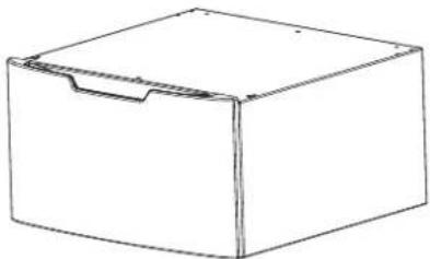
KIT CONTAINS
□Pedestal or Riser
natural_image
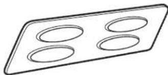
Simple line drawing of a rectangular box with a handle and side slot (no text or symbols)☐ Drawer Divider (Pedestal Kit Only)
natural_image
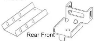
Simple line drawing of a rectangular tray with four circular indentations (no text or symbols)☐ Pedestal or Riser Brackets - 2 each
natural_image
Technical line drawing of two metal bracket components, one front view and one side view (no text or symbols)Or
natural_image
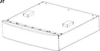
Simple line drawing of a rectangular box with two small rectangular cutouts on top (no text or symbols)☐ Installation Screws (#8-18 x 7/16) - 22

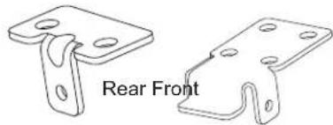
☐ Washer/Dryer Brackets - 2 each
natural_image
Technical line drawing of two metal bracket components labeled 'Rear Front' (no other text or symbols)TOOLS YOU WILL NEED
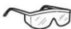
Safety Glasses
1/4" Socket & Nut Driver

□Gloves

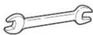
☐ 5/8" Open end wrench
Level

IMPORTANT: Shipping bolts should remain in place during installation.
PREPARE THE PEDESTAL/RISER
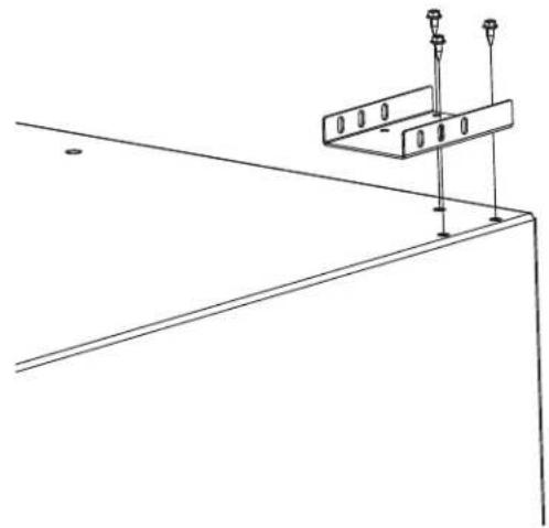
1 INSTALL REAR PEDESTAL/RISER BRACKETS
FOR DRYER AND 32" WASHER
Align rear pedestal/riser bracket as shown on both sides.
natural_image
Pure technical line drawing of a structural support frame with mounting holes and vertical supports (no text or symbols)FOR 34" WASHER
Install pedestal/riser bracket rotated 180° from dryer configuration.

natural_image
Pure technical line drawing of a structural support bracket with mounting holes (no text or symbols)2 INSTALL FRONT PEDESTAL BRACKETS
Install front pedestal/riser brackets on both sides.
natural_image
Technical line drawing of a mechanical clamp or bracket assembly (no text or symbols)PREPARE THE UNIT
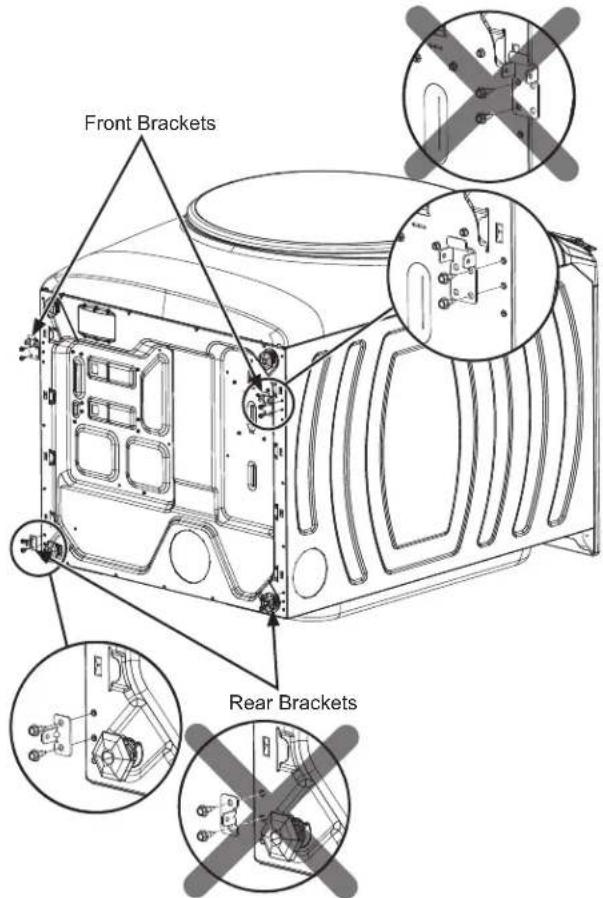
3 INSTALL WASHER/DRYER BRACKETS
Front Brackets
■ Lay the unit on its back on a protective surface.
■ Ensure leveling legs are threaded in to minimum height position.
■ Install front brackets on the bottom of the washer or dryer as shown. Use the 2 holes closest to the front and the 2 outermost holes on the bracket. The bracket should not go beyond the edge of the appliance.
text_image
Front Brackets Rear BracketsRear Brackets
■ Install rear brackets on the bottom of the washer or dryer as shown above. Use the top 2 holes on the bottom of the appliance with the tab on the bracket facing the outside.
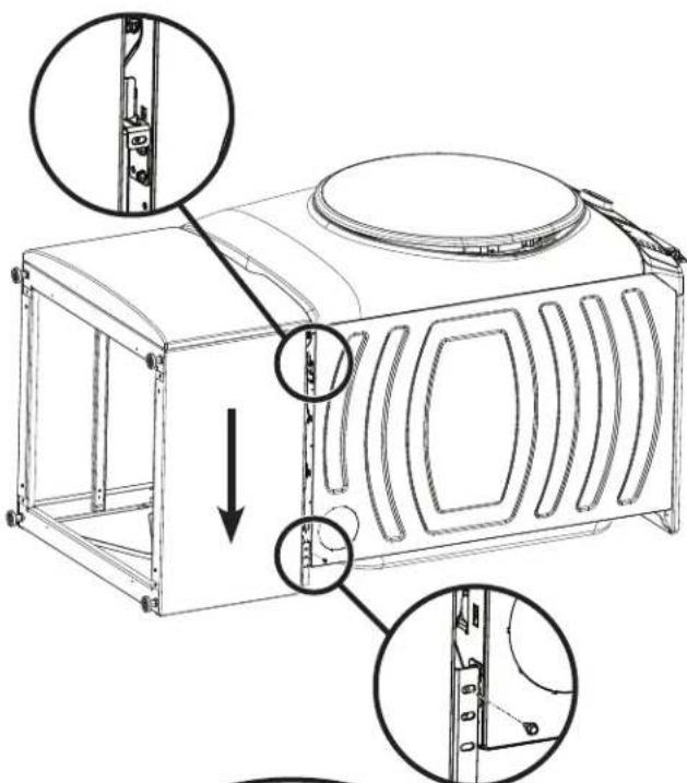
ATTACH PEDESTAL/RISER TO UNIT
4 JOIN REAR BRACKETS
■ Lift pedestal/riser and hook front brackets of pedestal/riser to front brackets of washer or dryer.
■ Align rear brackets on washer or dryer with rear brackets on pedestal/riser and fasten with screws. Make sure the bracket from the appliance is to the INSIDE of the pedestal/riser bracket and not the outside.
text_image
Technical diagram of a microwave oven with labeled parts and directional arrows indicating assembly or installation steps.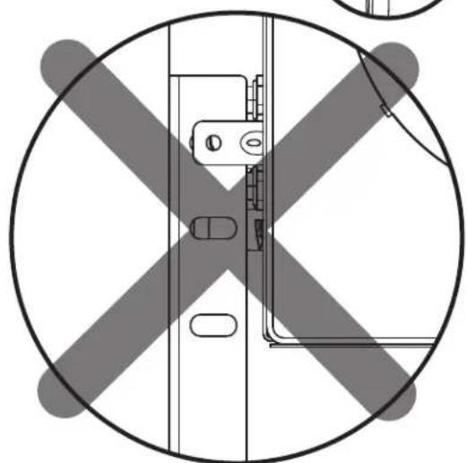
natural_image
Top-down schematic of a vehicle cross-section with no text or symbolsATTACH PEDESTAL/RISER TO UNIT (cont.)
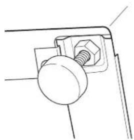
5 LEVEL THE WASHER OR DRYER
■ Locate the 4 legs from the parts package and install to minimum height.
■ Stand the washer or dryer upright.
■ Make sure that the washer or dryer is level by placing a spirit level on top. Check side to side and front to back.
■ Use a 5/8" open ended wrench to adjust the legs in and out. Tighten the lock nut against the bottom of the pedestal/riser.
NOTE: To minimize vibration, the locking nuts must be tight.
natural_image
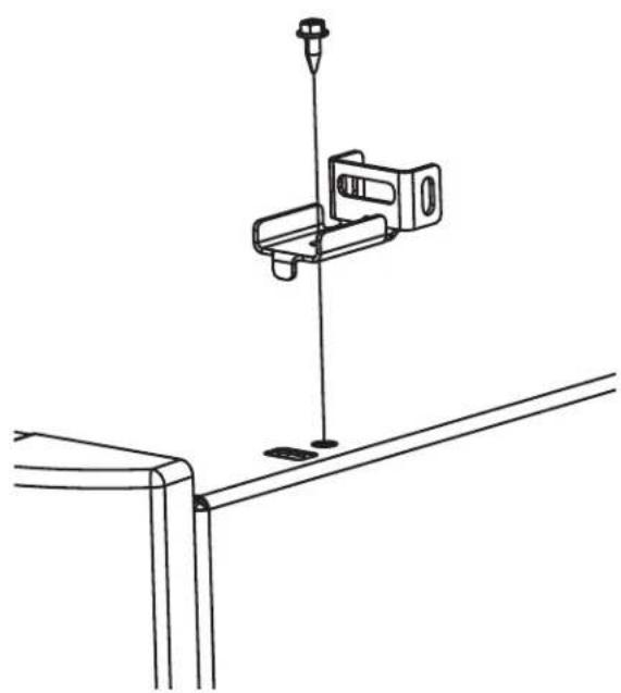
Technical line drawing of a mechanical component with a bolt and nut (no text or symbols)6 JOIN FRONT BRACKETS
■ Fasten screw between front brackets for pedestal/riser and washer or dryer on both sides of unit.
natural_image
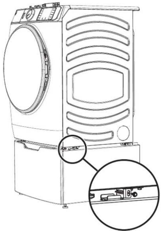
Line drawing of a front-loading washing machine with side-mounted door and control panel, showing internal components and mounting bracket (no text or symbols)7 WASHING MACHINE ONLY: REMOVE SHIPPING SCREWS
Remove the 4 shipping bolts on the back side of the unit.
8 FINALIZE THE INSTALLATION
Refer to the washer or dryer installation instructions to complete the installation.
natural_image
Pure technical line drawing of a structural support frame with mounting holes and vertical supports (no text or symbols)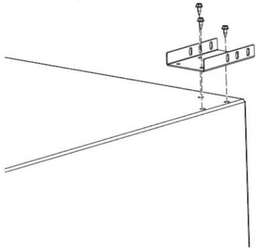
natural_image
Technical line drawing of a structural support bracket with mounting holes and vertical supports (no text or symbols)2 INSTALLER LES SUPPORTS DE PIÉDESTAL AVANT
natural_image
Technical line drawing of a mechanical clamp or bracket assembly with a vertical rod and mounting base (no text or symbols)PRÉPARER L'APPAREIL
3 INSTALLER LES SUPPORTS DE LAVEUSE/SÉCHEUSE
Supports avant
text_image
Supports avant Supports arrièreSupports arrière
text_image
Technical diagram showing assembly of a device with labeled parts and cross-sectional viewFIXER LE PIÉDESTAL/ÉLÉVATEUR À L'APPAREIL (SUITE)
5 METTRE LA LAVEUSE OU LA SÉCHEUSE DE NIVEAU
natural_image
Technical line drawing of a mechanical clamp or bracket with a bolt and nut (no text or symbols)6 JOINDRE LES SUPPORTS AVANT
natural_image
Line drawing of a front-loading washing machine with internal components and mounting bracket (no text or symbols)7 LAVEUSE SEULEMENT : RETIRER LES BOULONS D'EXPÉDITION
natural_image
Simple line drawing of a rectangular box with two small rectangular cutouts on top (no text or symbols)natural_image
Pure technical line drawing of a structural support frame with mounting holes and vertical supports (no text or symbols)