
CAM 030 - Dashcam CALIBER - Free user manual and instructions
Find the device manual for free CAM 030 CALIBER in PDF.
| Product Type | Rear view camera (dashcam) with monitor not included |
| Brand | Caliber |
| Model | CAM 030 |
| Approximate Dimensions | 70 x 50 x 30 mm (not communicated) |
| Approximate Weight | 100 g (not communicated) |
| Power Supply | 12 V DC (via tail light) |
| Power Consumption | 0.3 A (estimated) |
| Viewing Angle | 120° (not specified) |
| Resolution | 640 x 480 pixels (estimated) |
| Video Output | Composite RCA (yellow) |
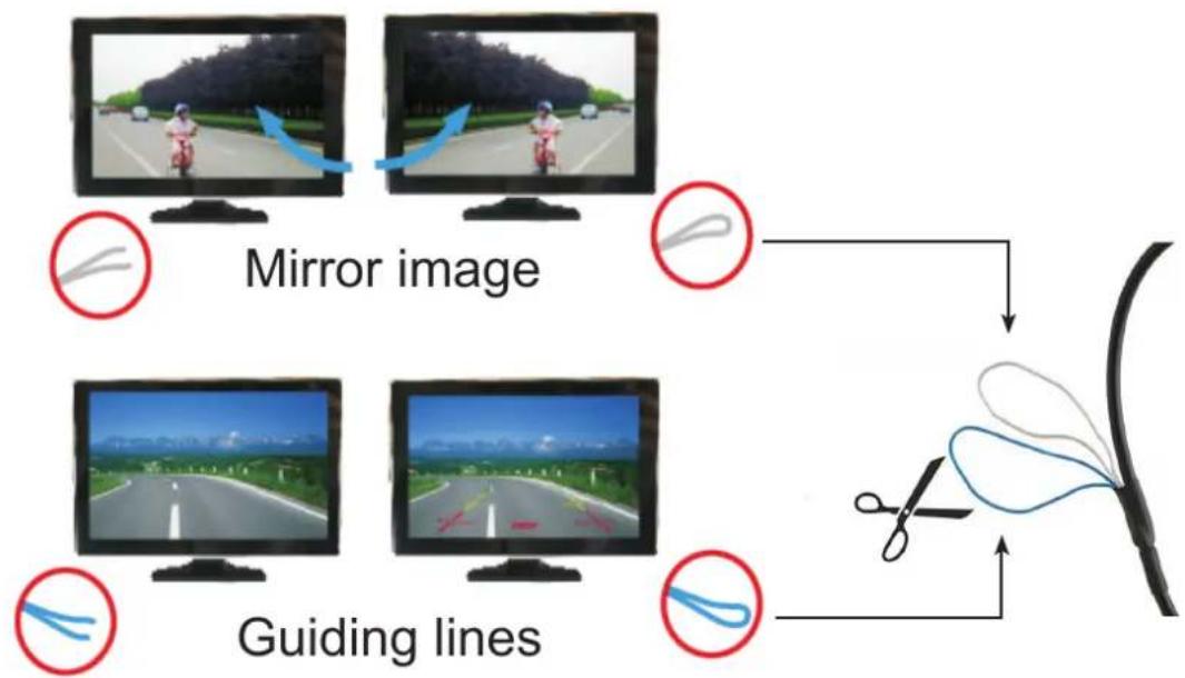
| Features | Guidelines (cut blue wire), horizontal mirror (cut white wire), automatic activation in reverse |
| Operating Temperature | -20 °C to 60 °C (not communicated) |
| Protection Rating | IP67 (not specified, estimate) |
| Waterproofing | Weather resistant (not specified) |
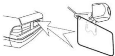
| Mounting | Flush mount (25 mm hole) or on bracket (above license plate) |
| Extension Cable | 6 meters (not communicated) |
| Supplied Accessories | Power cable with connectors, 25 mm drill, mounting housings (options A, B, C) |
| Compatibility | Monitors/screens with RCA video input and 12 V reverse signal |
| Standards | Compliant with RoHS (2011/65/EU) and RED (2014/53/EU) |
| Maintenance | Clean with a soft, dry cloth |
| Warranty | 2 years (not specified, estimate) |
Frequently Asked Questions - CAM 030 CALIBER
Ensure the red wire is only powered in reverse gear.
User questions about CAM 030 CALIBER
0 question about this device. Answer the ones you know or ask your own.
Ask a new question about this device
Download the instructions for your Dashcam in PDF format for free! Find your manual CAM 030 - CALIBER and take your electronic device back in hand. On this page are published all the documents necessary for the use of your device. CAM 030 by CALIBER.
USER MANUAL CAM 030 CALIBER
Multi language manual
GB·FR·DE·ES·S·NL
GB·FR·DE·ES·S·NL
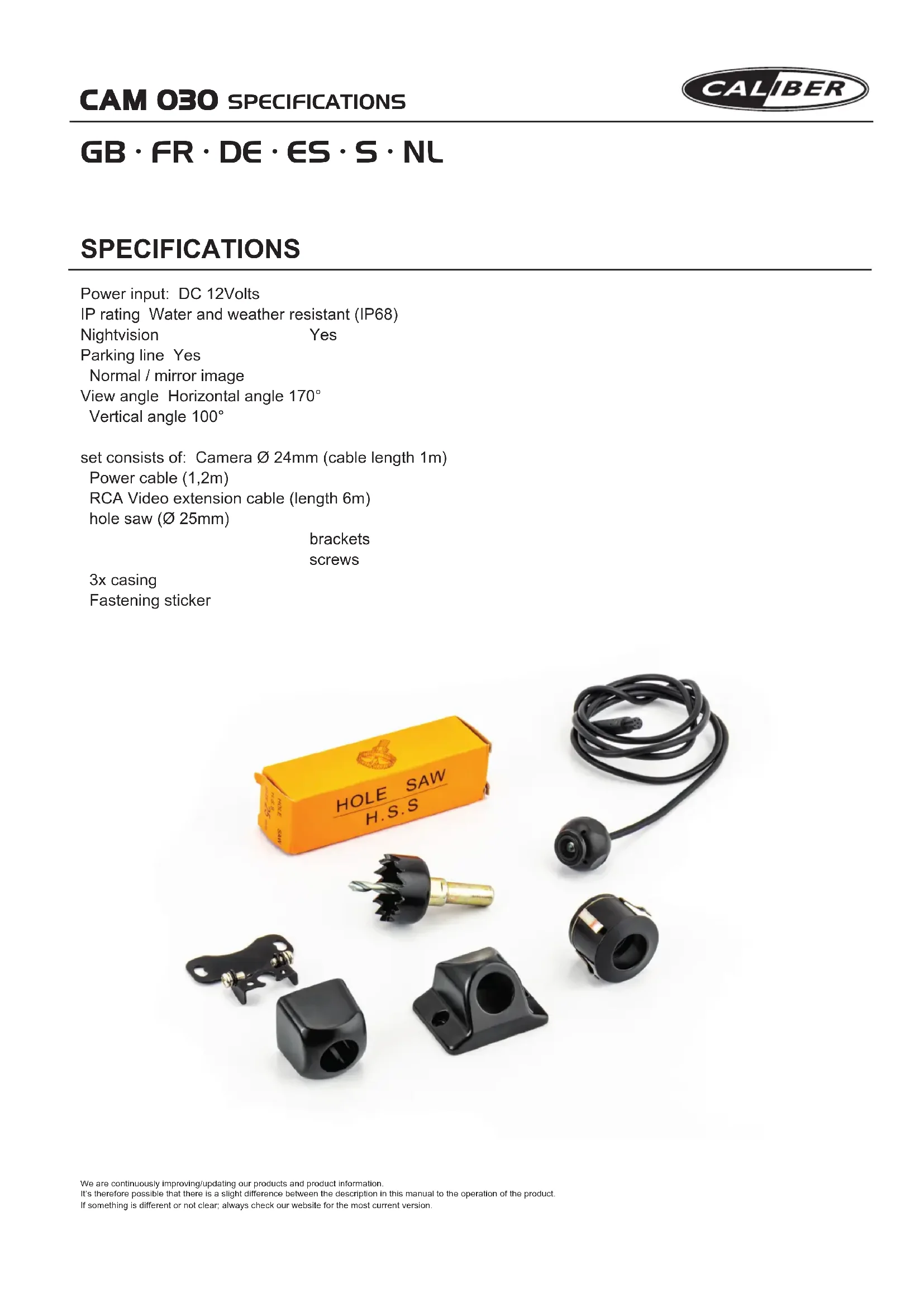
SPECIFICATIONS
Power input: DC 12Volts
IP rating Water and weather resistant (IP68)
Nightvision Yes
Parking line Yes
Normal / mirror image
View angle Horizontal angle 170^
Vertical angle 100^
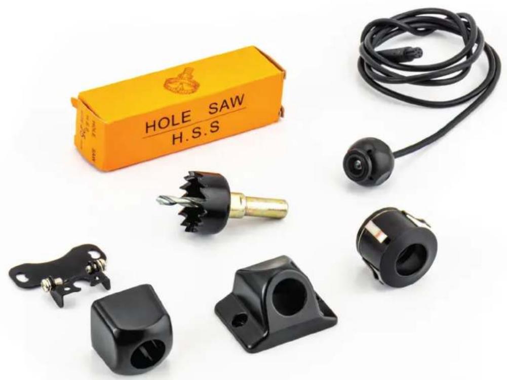
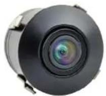
set consists of: Camera 24mm (cable length 1m )
Power cable (1,2m)
RCA Video extension cable (length 6m)
hole saw (Ø 25mm)
brackets
screws
3x casing
Fastening sticker
Warnings
The product is intended to assist in safe driving and to allow the driver to have a broader rear view while the vehicle is in reverse. You, as the driver, are solely responsible for the safe operation of your vehicle and the safety of your passengers according to local traffic regulations. Do not use any features of this system to the extent that it distracts you from safe driving. Your first priority while driving should always be the safe operation of your vehicle. Caliber Europe BV cannot accept any responsibility whatsoever for accidents resulting from failure to observe these precautions or safety instructions
-
This product utilizes high voltage. Any unauthorized modifications or damage to the product may result in electrical shock. Handle all components with care. Inspect regularly for damage to components and cabling.
-
You are responsible for ensuring that the installation of this product does not void or affect the vehicle manufacturer's warranty. Caliber Europe or its subsidiaries are not liable in full or in part for improper installation resulting in loss or damage to your property, or for voiding all or part of the vehicle manufacturer's warranty.
-
Do not apply excessive force to any of the components contained within this kit. Excessive force used before, during or after installation that results in a damaged or non-functional part will void all warranties.
-
Please follow the procedures in this installation manual. Improper installation or modification of this product will void all warranties.
Installing the CAM030
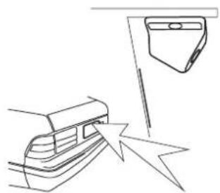
Look for a location that will give you the best view behind the vehicle. This should not be directly next to or under a reverse/ backup lamp as it may blind the camera at night. Avoid license plate lamps as well as they too can blind the camera at night.
Determine which casing option (A/B/C) is most suitable for your vehicle.
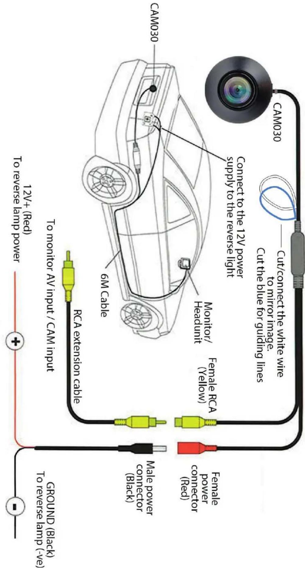
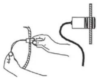
Wire the camera's power wire to the vehicle's reverse lamp:
a) Locate the reverse lamp in the tail light assembly
b) Using a crimp connector or by soldering attach the red wire to the positive 12 volt wire from the reverse lamp. This should only have power when the car is in reverse gear and the white lamp illuminated. Attach the black wire to the Ground (Negative 12 Volts only).
Run the extension cable to the location of the monitor/head-unit (not included) and connect the other end of the extension cable to the camera. Yellow RCA connected to the Video/CAM input.
Blue wire:
Cut to turn off the guiding lines*
White wire:
Cut to horizontally mirror the image on screen*
*Turn the camera OFF and ON again for the cut to take effect
Head-unit
On some head-units you need to connect the 12V red wire to the 'back cam' wire on your head-unit. The screen will automatically turn ON when reversing.
A
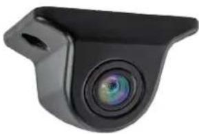
Option A) Built-in mounting casing
Find a suitable location (depending on the type of vehicle in the area at the rear, bumper). Drill a hole with a diameter of 25mm (drill bit included), and insert the camera.
B
Option B) Built-on mounting casing
Find a suitable location (depending on the type of vehicle in the area at the rear, above the number plate).
C
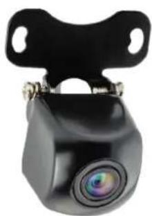
Option C) Built-on mounting casing
Find a suitable location (depending on the type of vehicle in the area at the rear, E.G above about the number plate).
Avertissements
GB Caliber hereby declares that the item CAM030 is in compliance with the essential requirements and other relevant provisions of Directive 2011/65/EU (RoHS) and 2014/53/EU (RED)
GB Old appliances and/or batteries must not be disposed with garbage! If the device/battery can not be used anymore, every user is legally obliged to dispose of old appliances and/or batteries separated from the garbage, e.g. at a collection point of his municipality/district.

Brand : CALIBER
Model : CAM 030
Category : Dashcam