5IE84252 - Cooker BLAUPUNKT - Free user manual and instructions
Find the device manual for free 5IE84252 BLAUPUNKT in PDF.

| Product Type | Built-in Induction Hob |
| Brand | Blaupunkt |
| Model | 5IE84252 |
| Dimensions (W x D x H) | 750 x 490 x 52 mm |
| Cutout Dimensions (W x D) | 780 x 520 mm |
| Total Power | 7400 W |
| Number of Cooking Zones | 4 (induction) |
| Control Type | Touch controls and Smart Slider |
| Special Functions | Booster, Timer, Stop & Go, Memory, Keep Warm, Automatic Preheat |
| Integrated Hood Control | Blaupunkt Multi Control (manual, semi-automatic, automatic) |
| Safety | Child lock, automatic shut-off, pan detection, residual heat indicator |
| Power Supply | 230 V ~ 50/60 Hz (1 phase + N) or 400 V ~ 50/60 Hz (2 phases + N) |
| Recommended Fuse | 25 A (single-phase) or 16 A (two-phase) |
| Cable Cross-section | 3 x 2.5 mm² (single-phase) or 4 x 1.5 mm² (two-phase) |
| Cleaning | Damp cloth, mild detergent; do not use steam cleaner |
| Compatible Cookware Materials | Steel, cast iron, enameled steel, stainless steel with magnetic base |
| Environmental Protection | Recyclable packaging, do not dispose of the appliance with household waste |
| Installation | By a qualified electrician; observe safety distances (minimum 40 mm from walls) |
Frequently Asked Questions - 5IE84252 BLAUPUNKT
User questions about 5IE84252 BLAUPUNKT
0 question about this device. Answer the ones you know or ask your own.
Ask a new question about this device
Download the instructions for your Cooker in PDF format for free! Find your manual 5IE84252 - BLAUPUNKT and take your electronic device back in hand. On this page are published all the documents necessary for the use of your device. 5IE84252 by BLAUPUNKT.
USER MANUAL 5IE84252 BLAUPUNKT
natural_image
Illustration of frying panes and a smiling face with no text or symbols, accompanied by neutral expressions (no readable text or symbols)GESCHIRRGRÖSSE
natural_image
Symbol of a trash bin crossed with diagonal lines, representing waste sorting or disposal (no text or labels)MONTAGEHINWEISE
3 Precautions before start-up
4 Important safety instructions
5 Protection against damage
6 Precautions in case of appliance failure
6 Protection against other hazards
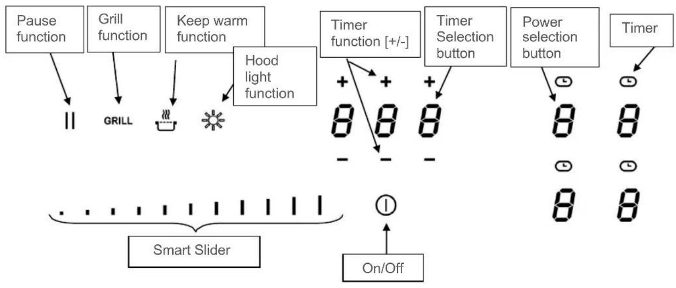
7 APPLIANCE DESCRIPTION
7 Technical description
9 Operating panel
9 OPERATING THE HOB
9 Display
10 Ventilation
10 STARTING UP THE HOB
10 Before first use
10 Induction principle
11 Touch control function
11 Smart Slider function
11 Switching the hob on/off
12 Pot detection
12 Residual heat display
13 Booster function (power level)
14 Timer
15 Automatic preheating
16 Stop & Go function
16 Memory function
17 Keep warm function
17 Automatic bridge and bridge function (models 5ll84251,5ll94291)
18 Child lock / locking the hob
18 Grill function (models 5II84251,5II94291)
19 COOKING RECOMMENDATIONS
19 Cookware
20 Cookware size
21 Setting ranges
21 STARTING UP THE HOOD (NOT FOR 5IZ34291)
21 Blaupunkt Multi Control – unique connection between hob and hood
22 Switching hood lighting on/off
22 Selecting hood management mode
23 Setting the ventilation power
23 Booster function
24 Default speed setting in semi-automatic mode
24 Ventilation timer
25 CLEANING AND MAINTENANCE
25 WHAT TO DO IF
27 ENVIRONMENTAL PROTECTION
27 INSTALLATION INSTRUCTIONS
29 ELECTRICAL CONNECTION
SAFETY
PRECAUTIONS BEFORE START-UP
- Remove all parts of the packaging.
- The appliance may only be installed and connected by a qualified electrician. The manufacturer cannot be held responsible for damage caused by errors in installation or connection. Only use the appliance when it is installed.
- The appliance may only be used when it is erected and installed in a piece of furniture and a confirmed and adjusted work plan is used.
- This appliance may only be used for the household cooking and frying of food and is not intended for commercial purposes.
- Remove all labels and stickers from the glass.
- The appliance may not be modified.
- Do not use the hob as a work surface or storage area.
- Safety is only guaranteed if the appliance is connected to a protective conductor that complies with the applicable regulations.
- The appliance may not be connected to the power supply via an extension cable.
- The appliance may not be used over a dishwasher or tumble dryer: the water vapours released could damage the electronics.
- Do not switch on the appliance using an external timer or a separate remote control.
-
CAUTION: The cooking process must be monitored. A short-term cooking process must be constantly monitored.
-
Switch off the cooking zones after each use.
• Overheated fats and oils ignite quickly. If you prepare dishes in fat or oil (e.g. chips), you should observe the cooking process. - When you cook and fry, the cooking zones become hot. For this reason, protect yourself from burns while and after using the appliance.
- Ensure that no electrical cable from a freestanding or built-in appliance comes into contact with the panel or the hot cooking zone.
- Magnetic objects such as credit cards, diskettes, pocket calculators, etc. must not be in the immediate vicinity of the appliance when it is switched on. Their function could be impaired.
- Metal objects such as knives, forks, spoons and pot lids should not be placed on the hob as they could become hot.
- In general, do not place any metal objects (e.g. spoons, pot lids, etc.) on the induction surface, as they may heat up during operation.
- Never cover the cooking surface with a cloth or protective foil; these could become very hot and catch fire.
- This appliance can be used by children from the age of 8 years and above and persons with reduced physical, sensory or mental abilities or a lack of experience and knowledge if they are supervised or if they are instructed in the safe use of the appliance and understand the resulting hazards.
• Children may not play with the appliance. -
Cleaning and user maintenance may not be carried out by children without supervision.
-
Do not use any pots or pans with unpolished or damaged bases (e.g. made of cast iron). These can scratch the glass ceramic panels.
- Note that grains of sand can also cause scratches.
- Glass ceramic is insensitive to temperature shocks and very resistant, but it is not unbreakable. Especially pointed and hard objects that fall onto the cooking surface can damage them.
- Do not knock pots and edges against the panel.
- Do not use the cooking zones with empty cookware.
- Avoid placing sugar, plastic or aluminium foil on the hot cooking zones. These materials melt, stick firmly and can therefore lead to cracks, fractures or other permanent changes in the panel when cooling down. If they still get onto the hot cooking zones, please switch off the appliance and remove these substances while they are still hot. As the cooking zones are hot, there is a risk of burns.
- Do not place any objects on the cooking zone.
- Never place hot cookware on the control unit. The electronics under the glass could be damaged.
- If there is a drawer under the built-in appliance, make sure there is a minimum distance of 2 cm between the underside of the appliance and the contents of the drawer, otherwise the ventilation of the appliance is not guaranteed.
- No flammable objects (e.g. aerosol cans) may be stored in this drawer. Any cutlery trays in the drawer must be made of heat-resistant material.
- Do not heat closed containers (e.g. tins) on the cooking zones. The containers or tins can burst due to the resulting excess pressure, resulting in a risk of injury!
PRECAUTIONS IN CASE OF APPLIANCE FAILURE
- If an error is detected, the appliance must be switched off and disconnected from the mains.
- If breaks, fissures or cracks occur on the glass: Immediately switch off the hob, unscrew or remove the hob fuse, and contact our customer service or your specialist retailer.
• Repairs to the appliance may only be carried out by qualified personnel. - WARNING: If the glass surface is cracked, switch off the appliance to avoid the risk of electric shock.
PROTECTION AGAINST OTHER HAZARDS
- Make sure that the cookware is always centred on the cooking zone. The base of the pan must cover as much of the cooking zone as possible.
- For persons with a pacemaker: an electromagnetic field is generated near the appliance when it is switched on, which could possibly affect the pacemaker. In case of doubt, please contact the manufacturer of the pacemaker or your doctor.
- Do not use cookware made of aluminum or plastic: it could melt on the hot cooking zones.
- NEVER try to extinguish a fire with water. Switch the device off and then cover the flame, e.g. with a lid or a fire blanket.
WARNING
The use of pots of poor quality or of an adapter disc for induction will lead to a premature termination of the warranty. The manufacturer accepts no liability for damage that may occur on or near the hob.
APPLIANCE DESCRIPTION
TECHNICAL DESCRIPTION
* These outputs may vary depending on the shape, size and quality of the pots.
| Type | 5IE64252 | 5IE84252 | 5II84251 | 5II94291 | 5IB64211 | 5IZ34291 |
| Total power | 7400W | 7400 W | 7400 W | 7400 W | 6700 W | 3700 W |
| Energy consumption of the hob EChob** | 180 Wh/kg | 180 Wh/kg | 173.4 Wh/kg | 175.3 Wh/kg | 180.7 Wh/kg | 177.3 Wh/kg |
| Front left cooking zone | ∅ 200 mm | ∅ 160 mm | 210x190mm | 210x190mm | ∅ 200 mm | ∅ 160 mm |
| Minimum pot base diameter | ∅ 110 mm | ∅ 90 mm | ∅ 110 mm | ∅ 110 mm | ∅ 110 mm | ∅ 90 mm |
| Nominal power* | 2300 W | 1400 W | 2100 W | 2100 W | 2300 W | 1400 W |
| Booster power* | 3000 W | 2100 W | 3000 W | 3000 W | 3000 W | 2100 W |
| Standardised cookware category** | C | A | C | C | C | A |
| Energy consumption ECcw** | 182.9 Wh/kg | 191.8 Wh/kg | 159.5 Wh/kg | 159.5 Wh/kg | 182.9 Wh/kg | 191.8 Wh/kg |
| Rear left cooking zone | ∅ 160 mm | ∅ 200 mm | 210x190mm | 210x190mm | ∅ 160 mm | ∅ 160 mm |
| Minimum pot base diameter | ∅ 90 mm | ∅ 110 mm | ∅ 110 mm | ∅ 110 mm | ∅ 90 mm | ∅ 90 mm |
| Nominal power* | 1400 W | 2300 W | 2100 W | 2100 W | 1400 W | 1400 W |
| Booster power* | 2100 W | 3000 W | 3000 W | 3000 W | 2100 W | 2100 W |
| Standardised cookware category** | A | C | C | C | B | B |
| Energy consumption ECcw** | 191.8 Wh/kg | 182.9 Wh/kg | 159.5 Wh/kg | 159.5 Wh/kg | 162.7 Wh/kg | 162.7 Wh/kg |
| Rear right cooking zone | ∅ 200 mm | ∅ 200 mm | 210x190mm | 210x190mm | - | - |
| Minimum pot base diameter | ∅ 110 mm | ∅ 110 mm | ∅ 110 mm | ∅ 110 mm | - | - |
| Nominal power* | 2300 W | 2300 W | 2100 W | 2100 W | - | - |
| Booster power* | 3000 W | 3000 W | 3000 W | 3000 W | - | - |
| Standardised cookware category** | C | C | B | B | - | - |
| Energy consumption ECcw** | 182.9 Wh/kg | 182.9 Wh/kg | 188 Wh/kg | 188 Wh/kg | - | - |
| Front right cooking zone | ∅ 160 mm | ∅ 160 mm | 210x190mm | 210x190mm | ∅ 250 mm | - |
| Minimum pot base diameter | ∅ 90 mm | ∅ 90 mm | ∅ 110 mm | ∅ 110 mm | ∅ 110 mm | - |
| Nominal power* | 1400 W | 1400 W | 2100 W | 2100 W | 2300 W | - |
| Booster power* | 2100 W | 2100 W | 3000 W | 3000 W | 3000 W | - |
| Standardised cookware category** | B | B | A | A | D | - |
| Energy consumption ECcw** | 162.7 Wh/kg | 162.7 Wh/kg | 186.4 Wh/kg | 186.4 Wh/kg | 196.5 Wh/kg | - |
| Central cooking zone | - | - | - | ∅ 200 mm | - | - |
| Minimum pot base diameter | - | - | - | ∅ 110 mm | - | - |
| Nominal power* | - | - | - | 2300 W | - | - |
| Booster power* | - | - | - | 3000 W | - | - |
| Standardised cookware category** | - | - | - | C | - | - |
| Energy consumption ECcw** | - | - | - | 182.9 Wh/kg | - | - |
** calculated on the basis of the method for measuring the functional properties (EN 60350-2).
flowchart
graph TD
    A["Pause function"] --> B["GRILL"]
    C["Grill function"] --> B
    D["Keep warm function"] --> E["Hood light function"]
    F["Timer function [+/-"]] --> G["8 8 8"]
    H["Timer Selection button"] --> I["8 8"]
    J["Power selection button"] --> K["8 8"]
    L["Timer"] --> M["On/Off"]
    N["Smart Slider"] --> O["On/Off"]
    P["On/Off"] --> Q["On/Off"]
OPERATING THE HOB
DISPLAY
| Display | Name | Description |
| 0 | Zero | The hub is activated |
| 1...9 | Power level | The power setting |
| U | No pot detection | Pot not in place or not suitable |
| A | Automatic preheating | Maximum power + preheating |
| E | Error display | Electronics error |
| H | Residual heat | Hob is hot |
| P | Booster | Booster power is activated |
| U | Keep warm function | With this function, food is kept warm at 70°C. |
| II | Pause | The hob is on pause |
| Π | Bridge | Two cooking zones can be combined into one cooking zone |
| GRILL | Grill function | The grill function is activated |
| Ω | Hood – Manual operation | Ventilation takes place in manual mode |
| Δ | Hood – Semi-automatic operation | Ventilation takes place in semi-automatic mode |
| Δ | Hood – Automatic operation | Ventilation takes place in automatic mode |
The fan works automatically. It starts at low speed as soon as the values released by the electronics exceed a certain threshold.
The higher speed is activated when the induction hob is used intensively. The fan reduces its speed and switches off automatically as soon as the electronics have cooled down sufficiently.
STARTING UP THE HOB
BEFORE FIRST USE
First clean your appliance with a damp cloth and then rub it dry with a clean cloth. Do not use any cleaning agent, which could cause a bluish tint on the glazed surface.
INDUCTION PRINCIPLE
Under each cooking zone is an induction coil. When the cooking zone is switched on, the induction coil generates a variable electromagnetic field. The magnetic field generates inductive currents in the base of the pot, which must be magnetic. As a result, the base of the pot, which is located on the heating zone, heats up. The cooking zone heats up only indirectly through the heat emitted by the pot.
Induction cooking zones only work with magnetic cookware:
- Suitable induction cookware with a magnetic base such as: cast iron, steel, enamelled steel, stainless steel with a magnetic base.
- Unsuitable induction cookware: copper, aluminium, glass, wood, earthenware, ceramic, non-magnetic stainless steel.
The induction cooking zone is automatically adjusted to the size of the cookware. The cookware must not fall below a certain base diameter, otherwise the induction will not activate. Each pot base diameter must have a minimum size depending on the size of the cooking zone.
If the cookware is not suitable for induction, the [U] display will appear.
The hob is controlled by sensor buttons. These react to gentle touches of the glass with the finger. If you touch the buttons for about one second, the control commands are executed. Each reaction of the control buttons is acknowledged with an acoustic and/or visual signal.
For general use, only press one button at a time.
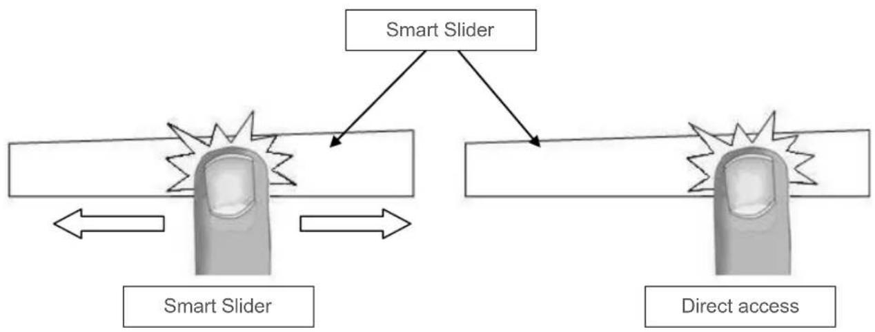
SMART SLIDER FUNCTION
To select the power level using the SMART SLIDER, move your finger on the SLIDER ZONE. The desired performance can also be selected directly by touching the respective level.
flowchart
graph TD
    A["Smart Slider"] --> B["Crash Detection"]
    B --> C["Smart Slider"]
    C --> D["Direct access"]
    D --> E["Crash Detection"]
    E --> F["Direct access"]
SWITCHING THE HOB ON/OFF
First switch on the hob and then the cooking zone.
| Hob: switch on/ switch off: | ||
| Operation | Operating panel | Display |
| Switch on | Press [1] for 2 sec. | Press [0] |
| Switch off | Press [1] for 2 sec. | None of [H] |
| Switch cooking zone on/off: | ||
| Operation | Operating panel | Display |
| Increase power | Slide your finger over the Smart Slider | [1] to [P] |
| Switch off | Slide your finger over the Smart Slider | [0] or [H] |
If no further input is made, the hob will switch off after approx. 20 seconds for safety reasons.
POT DETECTION
For greater comfort and simplicity, this hob is equipped with a control system.
Switch on the hob and place a pot on the hob. The intuitive operation will automatically detect the pot or will display the [0] symbol above the Smart Slider to be used. You can now adjust the cooking level as desired.
The pot detection feature ensures complete safety.
The induction system will not work:
- If there is no cookware on the cooking zone or if a pot unsuitable for induction is used. In this event, the power level cannot be increased and the [U] symbol will appear on the display. The [U] will disappear when a pot is placed on the cooking zone.
- If the pot is removed from the cooking zone during cooking, the cooking zone will immediately switch off and the [U] sign will appear in the display. The [U] will disappear when a pot is placed back on the cooking zone. The cooking zone then resumes at the previously set power level.
After use, switch off the cooking zone so that the [U] symbol no longer appears in the display.
RESIDUAL HEAT DISPLAY
After the cooking zones or hob have been switched off, the residual heat of the cooking zones that are still hot is displayed with an [H]. The [H] will disappear if the cooking zones can be touched safely. As long as the residual heat display is lit, the cooking zones should not be touched and no heat-sensitive objects should be placed on them: Risk of burns!
All cooking zones are equipped with a booster function, i.e. with power amplification. The booster function is displayed with [P].
If they are switched on, these cooking zones operate for a period of 10 minutes. This high power is intended to enable you to do things like quickly heating large quantities of water, to boil water for pasta for example. After the appliance has automatically switched back after 10 minutes, you should not switch back to the booster. The appliance could overheat and will trigger a safety shutdown.
| Switching booster on/off: | ||
| Operation | Operating panel | Display |
| Switch on booster | Slide your finger over the Smart Slider or press the end immediately | [ P ] |
| Switch off booster | Slide your finger over the Smart Slider or press the end immediately | [ 9 ] to [ 0 ] |
| Management of the maximum power: | |
| The hob is equipped with a maximum power level. To ensure that this maximum power is not exceeded, the electronics automatically reduce the cooking level of another cooking zone when the booster function is activated. This cooking zone will then display the reduced power [9] by flashing. | |
| Selected cooking zone | Other cooking zone (e.g.: Power level 9) |
| [ P ] lights up | [9] is reduced to [6] or [8] and flashes |
With the integrated timer, a cooking time of 1 to 999 minutes can be set on all four cooking zones. Each cooking zone can have a different setting.
| Activating or changing the duration: | ||
| Operation | Operating panel | Display |
| Select cooking zone | Press the corresponding cooking zone button | |
| Select power | Slide your finger over the Smart Slider | [1] to [P] |
| Select timer | Press [ ] | The display of the selected cooking zone will light up |
| Reduce time | Press [-] for the timer | [60] ... |
| Increase time | Press [ + ] for the timer | Time in min. will increase |
After a few seconds, the flashing will stop. The duration is activated and the time lapse begins.
| Switching off the timer: | ||
| Operation | Operating panel | Display |
| Select timer | Press [ ] | The display of the selected cooking zone will light up |
| Switch off timer | Press [-] to [000] | [000] |
If several timers are running, please repeat the procedure.
| Timer as egg timer: | ||
| The timer functions independently of the cooking zones and switches off as soon as one cooking zone is in operation. The process is carried out even if the hob is switched off. | ||
| Operation | Operating panel | Display |
| Switch on the hob | Press [1] for 2 sec. | [0] |
| Select timer | Press [000] | [000] |
| Reduce time | Press [-] for the timer | [60] ... |
| Increase time | Press [+] for the timer | Time in min. will increase |
After a few seconds, the flashing will stop. The duration is activated and the time lapse begins.
| Automatic switch off: |
| When the programmed cooking time has elapsed, [ 000 ] will flash and an acoustic signal will be given.To switch off the signal tone and flashing, simply press the [- ] or [ + ] button. |
AUTOMATIC PREHEATING
All cooking zones are equipped with automatic preheating. When the automatic preheating system is activated, the cooking zone automatically heats up at maximum power and then switches back to the cooking level you have selected. The preheating time depends on the selected continuous cooking level.
| Activating the automatic preheating feature: | |||
| Operation | Operating panel | Display | |
| Select power (e. g. « 7 ») | Slide your finger over the Smart Slider and remain for 3s | [7] flashes with [A] | |
| Set continuous cooking level | Automatic preheating Time (min:sec) | ||
| 1 | 00:40 | ||
| 2 | 01:12 | ||
| 3 | 02:00 | ||
| 4 | 02:56 | ||
| 5 | 04:16 | ||
| 6 | 07:12 | ||
| 7 | 02:00 | ||
| 8 | 03:12 | ||
| 9 | - : - | ||
| Switching off the automatic preheating feature: | ||
| Operation | Operating panel | Display |
| Select power | Slide your finger over the Smart Slider | [0] to [9] |
STOP & GO FUNCTION
With this feature, you can temporarily interrupt the cooking process and restart with the same settings.
| Switching Stop & Go function on/off: | ||
| Operation | Operating panel | Display |
| Switch on Stop & Go | Press [ II ] for 2s | [ II ] on displays |
| Switch off Stop & Go | Press [ II ] for 2s | Flashing Smart Slider |
| Press the flashing Smart Slider | Former settings | |
MEMORY FUNCTION
After switching off the hob, the last settings remain stored. You can reactivate these values using the memory function. The following settings can be reactivated using the memory function:
• Power levels of the cooking zones.
- Timer settings of the cooking zones.
Settings of the automatic preheating function Calling up the memory function:
- Switch on hob (Press [ ] for 2 sec.)
- Press [ II ] within 6 seconds.
- The values of the last settings are reactivated.
With this function, food is kept warm at 70 °C . This function prevents overflow and burning.
| Switching on and off: | ||
| Operation | Operating panel | Display |
| Switch on | Press [ZCV5] | [U] |
| Switch off | Press  | [0] |
AUTOMATIC BRIDGE AND BRIDGE FUNCTION (MODELS 5II84251,5II94291)
This function allows two cooking zones to be linked together for a single cooking process.
| Process | Operating panel | Display |
| Switch on the hob | Press [1] for 2 sec. | [0] |
| Switch on bridge | Place a pot on one of the two cooking zones to be bridged and press the corresponding selection buttons | [0] and [7] |
| or place a large pan on both of the zones you wish to use with this function | [7] will flash [7] | |
| Increase power | Slide to the right over the Smart Slider that shows the power | [1] to [P] |
| Switch off bridge | Press the two desired zones | [0] |
To prevent the cooking zone setting from being altered, e.g. when cleaning the glass, the operating buttons (except the [①] button) can be locked.
| Activating the lock: | ||
| Operation | Operating panel | Display |
| Switch on the hob | Press [ ] for 2 sec. | [0] |
| Switch on lock | Hold the button of a cooking zone for 3s. Then place your finger on the Smart Slider and slide your finger from left to right | Light on |
| Switch off lock | Hold the button of a cooking zone for 3s. Then place your finger on the Smart Slider and slide your finger from right to left | Light off |
GRILL FUNCTION (MODELS 5II84251,5II94291)
This function allows optimum use of the Blaupunkt griddle / Teppan Yaki plate. By bridging two cooking zones and using a suitable power level, this feature guarantees a pure indoor grilling pleasure. You can find the right accessories in our online shop at www.blaupunkt-einbaugeraete.com or from your specialist retailer.
| Switching the grill function on/off: | ||
| Operation | Operating panel | Display |
| Switch on grill function | Press [ GRILL ] | |
| Switch off grill function | Press [ GRILL ] | [ 0 ] |
| Operating time limit: | |
| The hob has an automatic operating time limit. The continuous operating time of each cooking zone depends on the selected cooking level. A precondition is that no setting changes are made to the cooking zone during the period of use. The cooking zone is switched off once the operating time limit has responded. | |
| Set cooking level | Operating time limit (hours:min) |
| 1 | 08:36 |
| 2 | 06:42 |
| 3 | 05:18 |
| 4 | 04:18 |
| 5 | 03:30 |
| 6 | 02:18 |
| 7 | 02:18 |
| 8 | 01:48 |
| 9 | 01:30 |
COOKING RECOMMENDATIONS
COOKWARE
Suitable materials:
Steel, enamelled steel, cast iron, stainless steel with magnetic base, aluminium with magnetic base
Unsuitable materials:
Aluminium and stainless steel without magnetic base, copper, brass, glass, earthenware, porcelain
Check with the manufacturer's instructions to determine whether the cookware is suitable for induction.
To check the induction compatibility of pots:
- Fill the cookware with some water and place them on the induction cooking zone. Switch on the cooking zone at power level [9]. This water must heat up in a few seconds.
- Hold a magnet against the base of the cookware. If the magnet sticks, the cookware is suitable.
Certain pans can make a noise when placed on an induction cooking zone. This noise does not cause any interference with the appliance and has no influence on the cooking process.
The properties of the base of the cookware can influence the uniformity of the cooking result.
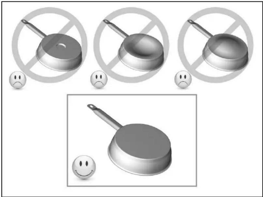
Only use pots and pans with a smooth base. Otherwise, rough pot or pan bases could scratch the glass ceramic panel.
Use pans with straight edges if possible. When using pans with sloping edges, induction also acts in the edge area of the pan. This can discolour the edge of the pan.
natural_image
Illustration of frying panes and smiling faces with no text or symbolsCOOKWARE SIZE
Up to a certain limit, the cooking zones automatically adjust to the size of the base of the pot. The cookware must not fall below a certain base diameter, otherwise the induction will not activate. Always centre the pot in the middle of the cooking zone to achieve the best possible efficiency.
(these data are approximate values)
| 1 to 2 | Melting, heating | Sauces, butter, chocolate, gelatin, pre-cooked dishes |
| 2 to 3 | Swelling, defrosting, keeping warm | Rice, pudding, sugar syrup, dried vegetables, fish, frozen products |
| 3 to 4 | Steaming | Vegetables, fish, meat |
| 4 to 5 | Steaming, swelling, defrosting | Steamed potatoes, soups, pasta, fresh vegetables |
| 6 to 7 | Preheating, continued cooking | Goulash, roulades, sausage, hard-boiled eggs |
| 7 to 8 | Gentle frying | Potatoes, fish, schnitzel, fried sausage, fried eggs |
| 9 | Bake, roast, boil water | Steaks, omelets, fried dishes, water |
| P | Cooking | Large quantities of water |
STARTING UP THE HOOD (NOT FOR 5IZ34291)
Blaupunkt Multi Control – unique connection between hob and hood
Calling up the user menu
Press the ON / OFF button a second time within 3 seconds after switching on. The "Pause" (||) button will flash. Keep this button pressed while simultaneously pressing all cooking zones clockwise (starting with the left front).
User menu «U9»
Select "U9" using the "Slider". The display will show 0 and 1 as available options. 0 is the default setting and means that the connection is deactivated.
Set the parameter "U9" to 1 to start the pairing process.
Press the On/Off button to save the setting and exit the pairing process. The Bluetooth connection will switch from pairing mode to normal mode.
SWITCHING HOOD LIGHTING ON/OFF
This function switches the hood light on or off.
| Operation | Operating panel | Display |
| Switch on hob | Press [1] for 2 sec. | [0] |
| Switch on hood lighting | Press [ *button | |
| Switch off hood lighting | Press [ *button |
SELECTING HOOD MANAGEMENT MODE
Three operating modes are available for the hood:
Manual mode: Manual setting of the ventilation intensity from the hob.
Semi-automatic mode: Ventilation starts automatically at a fixed intermediate level as soon as a cooking zone is activated (minimum level if no pans are detected). Ventilation is switched off when the cooking zones or hob are switched off (if the ventilation timer is not activated).
Automatic mode: The intensity of the ventilation automatically adjusts to the levels of the cooking zones.
When the hob is switched on, the last mode selected before it was switched off is activated.
| Operation | Operating panel | Display |
| Switch on hob | Press [1] for 2 sec. | [8] |
| Switch from semi-automatic to automatic | Press [8] for 3 sec. | [8] |
| Switch from automatic to manual | Press [8] for 3 sec. | [8] |
| Switch from manual to semi-automatic | Press [8] for 3 sec. | [8] |
SETTING THE VENTILATION POWER
The ventilation speed can be set in manual and semi-automatic mode. If an adjustment is made in the automatic mode, the management mode will switch to manual mode.
| Operation | Operating panel | Display |
| Select ventilation | Press ventilation display | [.] || |
| Increase power | Press the right side of the illuminated “Smart Slider” | |
| Decrease power | Press the left side of the illuminated “Smart Slider” | |
| Switch off ventilation | Press the right side of the illuminated slider for 3 sec. |
BOOSTER FUNCTION
The booster function increases the ventilation power. When the function is activated, the ventilation will operate for 6 minutes at a significantly higher power level.
The booster is used, for example, to vent large quantities of vapour.
| Operation | Operating panel | Display |
| Select ventilation | Press ventilation display | [.] || |
| Ventilation booster | Press the right side of the illuminated slider for 3 sec. |
The booster function can be stopped manually by stopping the ventilation or reducing the ventilation speed.
DEFAULT SPEED SETTING IN SEMI-AUTOMATIC MODE
The default speed used in semi-automatic mode can be adjusted if it is changed manually on the selected cooking zone within 10 seconds after starting ventilation.
| Operation | Operating panel | Display |
| Switch on hob | Press [1] for 2 sec. | [0] to [IMAGE] |
| Select cooking zone | Press a cooking zone display | [0] |
| Select power level | Press “Smart Slider” | [0] to [P] |
| Select ventilation | Press ventilation display | [IMAGE] |
| Increase or reduce speed | Press the illuminated “Smart Slider” | [IMAGE] |
VENTILATION TIMER
Your hood has a timed switch-off function, which allows you to run your ventilation 10 minutes before switching off. This function is particularly useful for removing vapour and any odours after cooking.
| Switching on the ventilation timer: | ||
| Operation | Operating panel | Display |
| Select ventilation | Press ventilation display | [ ] or [ ] or [ ] |
| Select timer | Press [ ] | Timer display on and display shows 10 min. |
| Switching off the ventilation timer: | ||
| Operation | Operating panel | Display |
| Select ventilation | Press ventilation display | [ ]or [ ] or [ ] |
| Select timer | Press [ ] | Timer display off |
CLEANING AND MAINTENANCE
Before cleaning the hob after cooking, you should first allow it to cool down.
Otherwise there is a risk of burns. Clean the dirty hob regularly. Use a damp cloth and a small amount of cleaning agent. Then rub it dry with a clean cloth.
- The appliance must be switched off before cleaning.
- Cleaning the appliance with a steam cleaner or high-pressure cleaner is not permitted for safety reasons.
- Never use abrasive or aggressive cleaning agents such as grill and oven sprays, stain or rust removers, scouring powders or sponges with scratchy surfaces.
• Afterwards, rub the hob dry with a clean cloth. - If things like sugar, plastic or aluminium foil accidentally get on the hob, you should switch off the hob as soon as possible and remove them immediately. Be very careful when doing so, as otherwise there is a risk of burns. Remove them immediately after switching off the cooking zones.
WHAT TO DO IF...
The hob or cooking zones cannot be switched on:
- The hob is incorrectly connected to the mains power.
- The fuse of the household installation is not inserted correctly or is defective.
- The hob is locked.
- The sensor buttons are covered with water or dirt.
- A pot or objects are covering the buttons.
The display shows [U]:
- The cookware is not on the cooking zone.
• The cookware is not suitable for induction - The diameter of the pot base is too small for this cooking zone.
The display shows [E]:
- Disconnect the appliance from the mains and reconnect it.
- Call customer service.
One cooking zone or the entire cooking zone switches off:
- The safety shutdown has been triggered.
-
Someone forgot to turn off a cooking zone.
• Several sensor buttons are covered. -
The pot is empty and overheated.
- Due to overheating, the electronics have automatically reduced or automatically switched off the power.
The cooling fan keeps running after it has been switched off:
• This is not a fault; the fan continues to run until the appliance has cooled down.
- The fan switches off automatically.
The automatic preheating function does not switch on:
• The cooking zone is still hot [H]
- The maximum power level is switched on [9].
Display [U]:
• Refer to the chapter on the keep warm level.
Display [ II ]:
• Refer to the chapter on the Stop&Go function.
The display shows [I] or [Er03]:
- An object or a liquid is covering the buttons. The display will disappear as soon as the buttons are released or cleaned.
The display shows [ E2 ]:
• The hob has overheated; let it cool down first and then turn it on again.
The display shows [ E8 ]:
- The air intake of the fan is clogged; please remove the things that are causing the interference.
The display shows [ U400 ]:
• The hob is not connected to the mains. Check the connection and turn on the hob.
The display shows [Er47]:
- The hob is not connected to the mains. Check the connection and turn on the hob.
If any of the above signs persist, please contact customer service.
ENVIRONMENTAL PROTECTION
The packaging materials are environmentally friendly and recyclable.
Electrical and electronic devices still contain valuable materials. However, they also contain harmful substances necessary for their function and safety.
- For this reason, never dispose of your old appliance in the residual waste.
• Instead, use the collection point provided by your local authority to return and recycle old electrical and electronic equipment.
natural_image
Symbol of a trash bin crossed out by diagonal lines, representing no waste or disposal (no text or labels)INSTALLATION INSTRUCTIONS
Only an authorised specialist may carry out installation and connection. The user must ensure that the standards applicable in his place of residence are observed.
Installing the seal
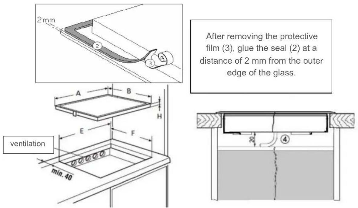
Installation
Insertion dimensions:
| A | B | E | F | H | |
| 5IE64252 | 590 mm | 520 mm | 560 mm | 490 mm | 52 mm |
| 5IE84252 | 780 mm | 520 mm | 750 mm | 490 mm | 52 mm |
| 5II84251 | 780 mm | 520 mm | 750 mm | 490 mm | 52 mm |
| 5II94291 | 880 mm | 520 mm | 810 mm | 490 mm | 52 mm |
| 5IB64211 | 590 mm | 520 mm | 560 mm | 490 mm | 52 mm |
| 5IZ34291 | 300 mm | 520 mm | 270 mm | 490 mm | 52 mm |
- The distance from the cut-out to a wall and/or a piece of furniture must be at least 40 mm.
- This appliance complies with type Y with regard to protection against fire hazards. Only appliances of this type may be installed on one side of adjacent tall cupboards or walls.
Caution: no furniture or appliances may be higher than the hob from the other side.
- The worktop must be finished with heat-resistant adhesive (75 °C).
- The wall edging strips must be heat-resistant.
- The hob must not be installed above stoves without fans, dishwashers, washing or drying appliances.
- To ensure adequate ventilation of the electronics in the hob, an air gap of 20 mm is required under the cavity.
- If there is a drawer under the hob, no flammable objects, e.g. aerosol cans, may be stored in the drawer.
- The safety distance specified by the manufacturer must be maintained between the appliance and an extractor hood. If not specified, this distance must be at least 650 mm.
- It must be ensured that the connection cable of the hob is not exposed to any mechanical stress after installation, e.g. by a drawer.
- The cutting surfaces of worktops should be sealed with special paint, silicone rubber or casting resin to prevent swelling due to moisture. Ensure that the sealing tape supplied is carefully applied.
- Never glue the hob with silicone! It will then no longer be possible to remove the hob later without destroying it.
- Do not use any unsuitable safety grilles or protective devices for the hob. This can lead to accidents.
Ventilation
- The rear wall of the base cabinet must be open in the area of the worktop cut-out to ensure an exchange of air.
- The distance between the induction hob and kitchen furniture or built-in appliances must be selected in such a way that adequate induction ventilation is ensured.
- Excessive heat development from below, e.g. from an oven without a cross-flow fan, must be avoided.
• If pyrolysis operations are carried out in built-in stoves, the induction hob may not be used.
ELECTRICAL CONNECTION
- To connect the appliance to the power supply, you should consult a qualified electrician who is thoroughly acquainted with the regulations of the local electrical supply companies and who will carefully observe them.
• The contact protection of operationally insulated parts must be ensured after installation. - Check the type label to see whether the required connection data correspond to those of the mains.
- It must be possible to disconnect all poles of the appliance from the mains using isolating devices. When switched off, there must be a contact clearance of 3 mm. Circuit breakers, fuses and contactors are considered suitable isolating devices.
- The installation must be protected by fuses. Electrical cables must be perfectly concealed by the installation.
- If the appliance is not equipped with an accessible plug, other means of disconnection must be taken into account for fixed installation in accordance with the installation instructions.
• The supply cable must be installed in such a way that it does not touch the hot parts of the hob.
Caution!
This appliance is only designed for a power supply of 230V/400 V \~ 50/60 Hz. Always connect the protective conductor. Please observe the wiring diagram.
The connection box is located on the bottom of the appliance. To open the casing, use a screwdriver and insert it into the slots provided. Tighten the screws in the connecting terminal block after 4 weeks.
Models 3 and 4 heating zones: 5IE64252, 5IE84252, 5II84251, 5IB64211
| Mains | Connection | Diameter | Cable | Fuse |
| 230V~50/60Hz | 1 phase + N | 3 × 2.5 mm^2 | H 05 VV - FH 05 RR - F | 25 A * |
| 400V~ 50/60Hz | 2 phases + N | 4 × 1.5 mm^2 | H 05 VV - FH 05 RR - F | 16 A * |
(*) as per standard EN 60 335-2-6

Connecting the hob
For the various connection options, use the brass terminal bridges located in the casing.
Single-phase connection 230V\~1P+N:
Place a terminal bridge between terminals L1 and L2, then between terminals N1 and N2. Connect the earthing to the « earth » terminal, the neutral to terminal N1 or N2, and phase L to terminal L1 or L2.
Two-phase connection 400V\~2P+N:
Place a terminal bridge between terminal N1 and N2.
Connect the earthing to the « earth » terminal, the neutral to terminal N1 or N2, phase L1 to terminal L1 and phase L2 to terminal L2.
Model 5 heating zones: 5II94291
| Mains | Connection | Diameter | Cable | Fuse |
| 230V~50/60Hz | 1 phase + N | 3 × 2.5 mm^2 | H 05 VV - FH 05 RR - F | 25 A * |
| 400V~ 50/60Hz | 2 phases + N | 4 × 1.5 mm^2 | H 05 VV - FH 05 RR - F | 16 A * |
| 400V~ 50/60Hz | 3 phases + N | 5 × 1.5 mm^2 | H 05 VV - FH 05 RR - F | 16 A * |
(*) as per standard EN 60 335-2-6

Connecting the hob
For the various connection options, use the brass terminal bridges located in the casing.
Single-phase connection 230V\~1P+N:
Place a terminal bridge between terminals L1 and L2, then between terminals L2 and L3 and then between terminals N1 and N2.
Connect the earthing to the « earth » terminal, the neutral to terminal N1 or N2, and phase L to terminal L1 or L2 or L3.
Two-phase connection 400V\~2P+N:
Place a terminal bridge between terminals L1 and L2, then between terminals N1 and N2. Connect the earthing to the « earth » terminal, the neutral to terminal N1 or N2, phase L1 to terminal L1 or L2 and phase L2 to terminal L3.
Three-phase connection 400V\~3P+N:
Place a terminal bridge between terminal N1 and N2.
Connect the earthing to the « earth » terminal, the neutral to terminal N1 or N2, phase L1 to terminal L1, phase L2 to terminal L2 and phase L3 to terminal L3.
Model 2 heating zones: 5IZ34291
| Mains | Connection | Diameter | Cable | Fuse |
| 230V~50/60Hz | 1 phase + N | 3 × 1.5 mm^2 | H 05 VV - FH 05 RR - F | 16 A * |
(*) as per standard EN 60 335-2-6
Caution! Insert the wires correctly and tighten the screws.
We are not responsible for incidents resulting from incorrect connections or non-existent or inadequate ground connections.
TABLE DES MATIÈRES
3 SÉCURITÉ
natural_image
Illustration of three frying panes with no crossed-out circles and sad face emojis, no text or symbols presentTAILLE DES CASSEROLES
natural_image
Symbol of a trash bin crossed out by diagonal lines, representing waste sorting or restriction (no text present)INSTRUCTIONS DE MONTAGE
7 APPARAATBESCHRIJVING
BESCHERMING TEGEN ANDERE GEVAREN
APPARAATBESCHRIJVING
natural_image
Illustration of frying panes and a smiling face with no text or symbols, accompanied by neutral expressions (no text or symbols present)GROOTTE VAN HET KOOKGEREI
natural_image
Symbol of a trash bin crossed out by diagonal lines, representing no waste or disposal (no text or labels)MONTAGE-INSTRUCTIES
natural_image
Illustration of frying panes and a smiling face with no text or symbols, accompanied by neutral expressions (no readable text or symbols)natural_image
Symbol of a trash bin crossed out by diagonal lines, representing waste sorting or disposal (no text or labels)ISTRUZIONI PER IL MONTAGGIO
INNEHÅLLSFÖRTECKNING
3 SÄKERHET
natural_image
Illustration of frying panes and smiling faces with no text or symbolsKOKKÄRLENS STORLEK
natural_image
Simple line drawing of a trash bin with crossed lines indicating no waste or restriction (no text or symbols)MONTERINGSHÄNVISNINGAR
natural_image
Illustration of frying panes with no crossed-out circles and sad face emojis, no text or symbols presentnatural_image
Symbol of a trash bin crossed out by diagonal lines, representing waste sorting or restriction (no text present)INDICACIONES DE MONTAJE