
893620 - Vacuum Cleaner MILWAUKEE - Free user manual and instructions
Find the device manual for free 893620 MILWAUKEE in PDF.
| Product Type | Wet/Dry Vacuum |
| Brand | Milwaukee |
| Model | 8936-20 |
| Voltage | 120 V AC |
| Rated Current | 12 A (motor: 9.5 A, built-in outlet: 8 A) |
| Tank Capacity | 7.5 gallons (28.4 L) |
| Airflow | 159 ft³/min |
| Water Lift | 59 inches (1499 mm H2O) |
| Suction Type | Dry and Wet |
| Switch | ON/OFF with AUTO function |
| Built-in Outlet | Yes, for power tool (max 8 A) |
| Filters | Cartridge, foam, cloth (optional) |
| Automatic Shut-off System | Float for shut-off when full |
| Use as Blower | No (models 8950 and 8955 only) |
| Grounding | Required (3-prong plug) |
| Warranty | 5 years (tool) |
| Filter Maintenance | Clean by tapping or rinsing, dry before dry use |
| Tank Drainage | Unplug, remove head, pour, rinse and dry |
Frequently Asked Questions - 893620 MILWAUKEE
User questions about 893620 MILWAUKEE
0 question about this device. Answer the ones you know or ask your own.
Ask a new question about this device
Download the instructions for your Vacuum Cleaner in PDF format for free! Find your manual 893620 - MILWAUKEE and take your electronic device back in hand. On this page are published all the documents necessary for the use of your device. 893620 by MILWAUKEE.
USER MANUAL 893620 MILWAUKEE
natural_image
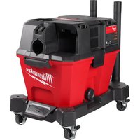
Exterior view of a Milwaukee air purifier with visible wheels and handle (no text or symbols on the device itself)Catalog No.
No de Cat.
Catálogo No.
8950
8955
8936-20
8938-20
natural_image
Black Milwaukee vacuum cleaner with wheels and handle, no visible text or symbols on the device itself.HEAVY-DUTY COMMERCIAL VACUUM EXTRA ROBUSTE ASPIRATEUR COMMERCIAL HEAVY-DUTY ASPIRADORA COMMERCIAL
TO REDUCE THE RISK OF INJURY, USER MUST READ AND UNDERSTAND OPERATOR'S MANUAL. AFIN DE RÉDUIRE LE RISQUE DE BLESSURES, L'UTILISATEUR DOIT LIRE ET BIEN COMPRENDRE LE MANUEL DE L'UTILISATEUR. PARA REDUCIR EL RIESGO DE LESIONES, EL USUARIO DEBE LEER Y ENTENDER EL MANUAL DEL OPERADOR.
GENERAL SAFETY RULES

WARNING!
READ AND UNDERSTAND ALL INSTRUCTIONS
Failure to follow all instructions listed below, may result in electric shock, fire and/or serious personal injury.
SAVE THESE INSTRUCTIONS
To reduce the risk of fire, electric shock or injury:
- Do not leave appliance when plugged in. Unplug from outlet when not in use and before servicing.
- Do not use outdoors or on wet surfaces.
- Do not allow to be used as a toy. Close attention is necessary when used by or near children.
- Use only as described in this manual. Use only manufacturer's recommended attachments.
- Do not use with damaged cord or plug. If appliance is not working as it should, has been dropped, damaged, left outdoors, or dropped into water, return it to a service center.
- Do not pull or carry by cord, use cord as a handle, close a door on cord, or pull cord around sharp edges or corners. Do not run appliance over cord. Keep cord away from heated surfaces.
- Do not unplug by pulling on cord. To unplug grasp the plug not the cord.
- Do not handle plug or appliance with wet hands.
- Do not put any object into openings. Do not use with any opening blocked; keep free of dust, lint, hair, and anything else that may reduce air flow.
- Keep hair, loose clothing, fingers, and all parts of body away from openings and moving parts.
- Do not pick up anything that is burning or smoking such as cigarettes, matches, or hot ashes.
- Do not use without dust bag and filter in place.
- Turn off all controls before unplugging.
-
Use extra care when cleaning on stairs.
-
Do not use to pick up flammable or combustible liquids such as gasoline or use in areas where they may be present.
- Connect to a properly grounded outlet only. See grounding instructions.
- Vacuum cleaners have motors and other parts that can produce sparks during normal use. Do not use within 30 feet of areas where explosive gases may be present (such as gasoline pumps and places where liquids like paint thinners, cleaners, solvents, etc. are stored).
- Unplug power cord whenever motor head is removed from tank.
- Do not use in the presence of explosive liquids or vapors.
- To reduce the risk of health hazards from vapors or dust, do not vacuum toxic, carcinogenic or other hazardous materials such as asbestos, arsenic, barium, beryllium, lead, pesticides or other health endangering materials.
- Do not use where oxygen or anesthetics are used.
- Wear electrically insulated footwear, such as rubber boots, when vacuuming wet material.
- WARNING! Some dust created by power sanding, sawing, grinding, drilling, and other construction activities contains chemicals known to cause cancer, birth defects or other reproductive harm. Some examples of these chemicals are:
- lead from lead-based paint
- crystalline silica from bricks and cement and other masonry products, and
• arsenic and chromium from chemically-treated lumber.
Your risk from these exposures varies, depending on how often you do this type of work. To reduce your exposure to these chemicals: work in a well ventilated area, and work with approved safety equipment, such as those dust masks that are specifically designed to filter out microscopic particles.
READ AND SAVE ALL INSTRUCTIONS FOR FUTURE USE.
Symbology
| Underwriters Laboratories, Inc. | |
| Canadian Standards Association | |
| Hz | Hertz |
| A | Amps |
Specifications
| Cat. No. | Volts AC | Amps | For Materials | Tank Capacity Gallons | Air Flow Cubic Feet per Minute | Sealed Suction in Water |
| 8936-20 | 120 | 12* | Wet or Dry | 7.5 | 159 | 59" |
| 8938-20 | 120 | 7.4 | Wet or Dry | 9 | 102 | 84" |
| 8950 | 120 | 8 | Wet or Dry | 8 | 143 | 45" |
| 8955 | 120 | 8 | Wet or Dry | 10 | 143 | 45" |
* For Cat. No. 8936-20 with onboard outlet:
The entire unit is rated at 12 amps. The vacuum motor is rated at 9.5 amps. The outlet on the motor head is rated at 8 amps.
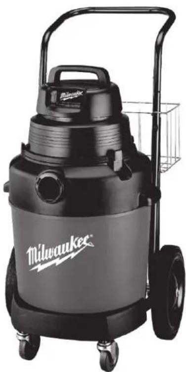
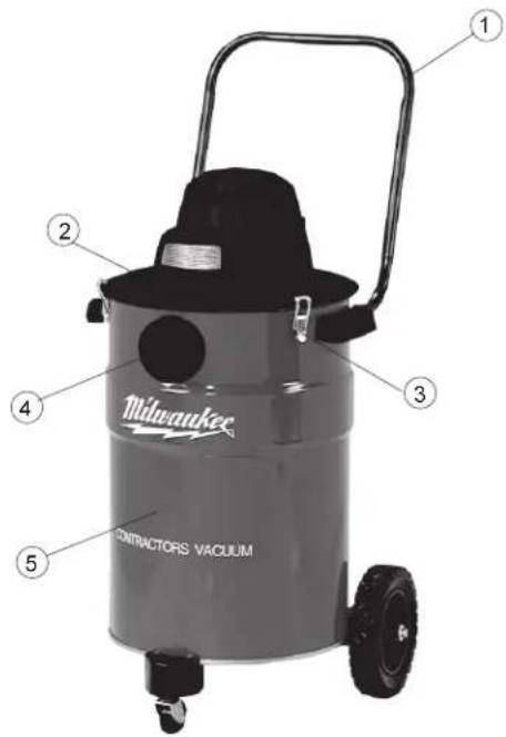
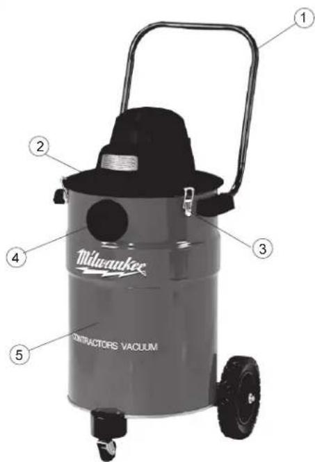
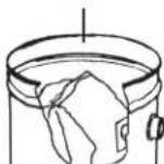
FUNCTIONAL DESCRIPTION
- Handle
- Exhaust port
- Tank latch
- Intake port
- Tank
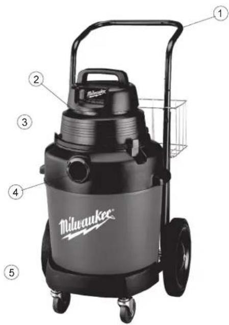
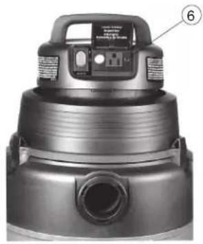
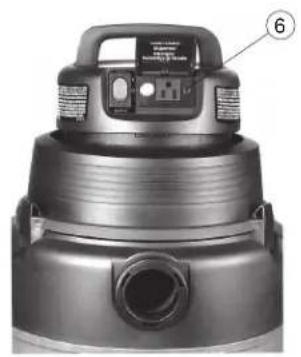
- Utility Outlet (Cat. No. 8936-20 only)
natural_image
Close-up of a black vacuum cleaner with labeled component (no visible text or symbols)
GROUNDING EXTENSION CORDS

WARNING!
Improperly connecting the grounding wire can result in the risk of electric shock. Check with a qualified electrician if you are in doubt as to whether the outlet is properly grounded. Do not modify the plug provided with the tool. Never remove the grounding prong from the plug. Do not use the tool if the cord or plug is damaged. If damaged, have it repaired by a MILWAUKEE service facility before use. If the plug will not fit the outlet, have a proper outlet installed by a qualified electrician.
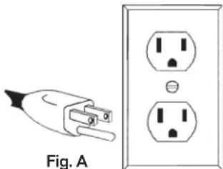
Grounded Tools:
Tools with Three Prong Plugs
Tools marked "Grounding Required" have a three wire cord and three prong grounding plug. The plug must be connected to a properly grounded outlet (See Figure A). If the tool should electrically malfunction or break down, grounding provides a low resistance path to carry electricity away from the user, reducing the risk of electric shock.
natural_image
Electrical plug and socket diagram showing a terminal block connected to an outlet (no text or symbols)The grounding prong in the plug is connected through the green wire inside the cord to the grounding system in the tool. The green wire in the cord must be the only wire connected to the tool's grounding system and must never be attached to an electrically "live" terminal.
Your tool must be plugged into an appropriate outlet, properly installed and grounded in accordance with all codes and ordinances. The plug and outlet should look like those in Figure A.
Double Insulated Tools:
Tools with Two Prong Plugs
Tools marked "Double Insulated" do not require grounding. They have a special double insulation system which satisfies OSHA requirements and complies with the applicable standards of Underwriters Laboratories, Inc., the Canadian Standard Association and the National Electrical Code. Double Insulated tools may be used in either of the 120 volt outlets shown in Figures B and C.
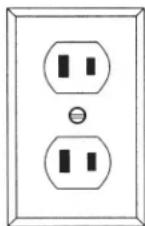
Fig. B
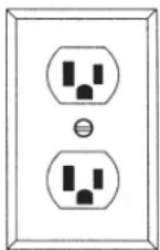
Fig. C
Grounded tools require a three wire extension cord. Double insulated tools can use either a two or three wire extension cord. As the distance from the supply outlet increases, you must use a heavier gauge extension cord. Using extension cords with inadequately sized wire causes a serious drop in voltage, resulting in loss of power and possible tool damage. Refer to the table shown to determine the required minimum wire size.
The smaller the gauge number of the wire, the greater the capacity of the cord. For example, a 14 gauge cord can carry a higher current than a 16 gauge cord. When using more than one extension cord to make up the total length, be sure each cord contains at least the minimum wire size required. If you are using one extension cord for more than one tool, add the nameplate amperes and use the sum to determine the required minimum wire size.
Guidelines for Using Extension Cords
- If you are using an extension cord outdoors, be sure it is marked with the suffix "W-A" ("W" in Canada) to indicate that it is acceptable for outdoor use.
- Be sure your extension cord is properly wired and in good electrical condition. Always replace a damaged extension cord or have it repaired by a qualified person before using it.
- Protect your extension cords from sharp objects, excessive heat and damp or wet areas.
Recommended Minimum Wire Gauge for Extension Cords*
| Nameplate Amperes | Extension Cord Length | |||||
| 25' | 50' | 75' | 100' | 150' | 200' | |
| 0 - 5 | 16 | 16 | 16 | 14 | 12 | 12 |
| 5.1 - 8 | 16 | 16 | 14 | 12 | 10 | -- |
| 8.1 - 12 | 14 | 14 | 12 | 10 | -- | -- |
| 12.1 - 15 | 12 | 12 | 10 | 10 | -- | -- |
| 15.1 - 20 | 10 | 10 | 10 | -- | -- | -- |
* Based on limiting the line voltage drop to five volts at 150% of the rated amperes.
READ AND SAVE ALL INSTRUCTIONS FOR FUTURE USE.
TOOL ASSEMBLY
Assembling Dolly (Cat. No. 8955) (Fig. 1)
Assemble as shown in the diagram. You will need a hammer and a phillips screwdriver.
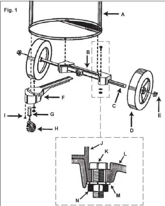
- Place wheels on rear frame (B) by tapping in the axle (C), fitting the wheel (D) on the axle and tapping a cap nut (E) on with a hammer.
- Insert caster socket (G) into front frame (F) and secure it with the phillips screw (I).
- Align front frame (F) and rear frame (B) so that they fit together and fit lip of tank (J) into the grooves in front and rear frames.
- Secure frame (B and F) to the tank by placing the hex bolts (K) through the holes in dolly and securing them with nut (N) and washer (M) as shown.
- Insert caster (H) into into caster socket (G) and push down until caster snaps into place.
Installing Handle (Cat. No. 8955) (Fig. 2)
You will need either a flat blade screwdriver or a socket driver and wrench or a pair of pliers.
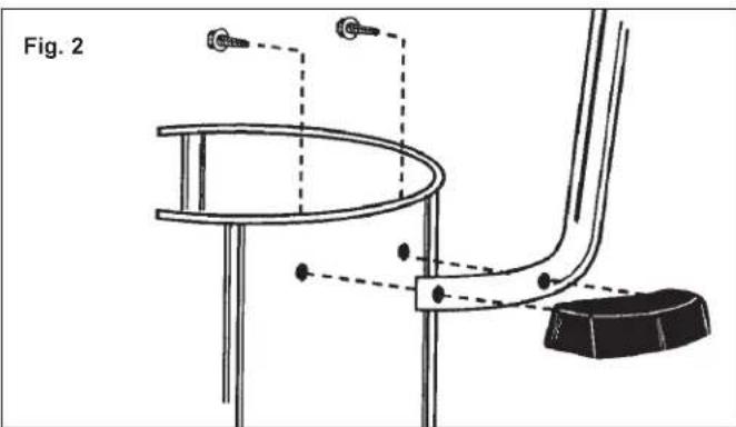
- Place dolly handle between tank and side handle on either side of the tank.
- Fasten tightly with slotted hex head screws.
Assembling Dolly (Cat. No. 8938-20) (Fig. 3)
Assemble as show in the diagram. You will need: a hammer, two 1/2" open end wrenches, and two 7/16" open end wrenches.
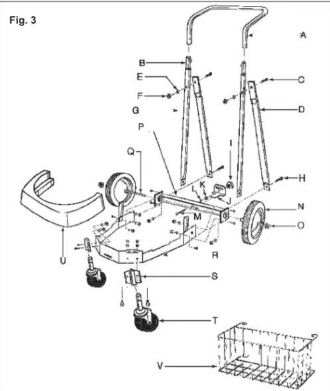
- Insert 2-1/2" bolt (M) through the center hole in rear frame (P), attach lockwasher (L) and nut (K) and tighten securely.
- Attach support struts (D) to back of rear frame (P) with 5/8" bolt, star washers, and nuts (finger tight only).
- Position main frame inside rear frame. Attach with (2) 5/8" bolts and, star washers, and nuts on each side (G).
- Attach handle uprights, inside main frame (Q) (make sure that buttons at the top face inward using 5/8" bolts, star washers and nuts finger tighten only). Align holes at the top of the struts (D) with hole in the handle uprights (G). Attach with 1-3/8" bolts, star washers, and nuts and tighten securely.
- Go back and tighten the bolts at the bottom of the uprights and struts (D).
- Attach caster socket plates (open end down) to front of main frame (R) using 5/8" bolts, star washers and nuts and insert casters (T) into the sockets.
- Attach the handle (A) onto the uprights by pushing down and holding buttons in.
- Place tank retaining bracket (J) through the slot in the back of the rear frame and thread on the knob.
- Place axle upright on a hard surface and tap a capnut (O) on with a hammer. Place one wheel on the axle and slide it down to the capnut. Slide the axle through the rear of frame and slide on the other wheel. Tap second capnut onto axle after checking that frame is assembled correctly by placing the tank on the dolly.
- Slide bumper (U) down over the socket plates until it snaps into place.
- Hook basket (V) on the handle with the top hooks around the handle and the bottom prongs in the holes in the handle.
Attaching Caddy and Casters (Cat. No. 8936-20)
You will only need a Phillips screwdriver.
- Slide caddy over attaching boss' on bottom of vacuum cleaner tank.
- Install phillips screws and tighten.
- Slide caster housings over attaching boss' on bottom of vacuum cleaner tank.
- Install phillips screws and tighten.
- Push caster wheel shafts into attaching holes on bottom of caster housings and bottom of caddy until they click.

WARNING!
To reduce the risk of injury, always unplug the tool before removing the motor head.
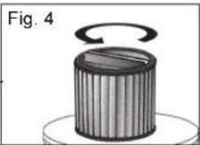
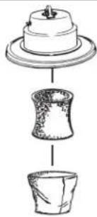
Installing and cleaning Cartridge Filters
- Unplug vacuum cleaner.
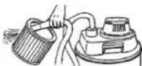
- To remove filter for cleaning, hold onto base of lid cage with one hand and turn retainer counter clockwise to loosen (Fig. 4).
Caution: Use care when handling motor head. Dropping motor head may cause permanent damage.
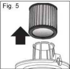
- Remove filter cartridge from motor head (Fig. 5). Handle filters carefully when removing for cleaning. Even a small hole can cause dust to be exhausted. Do not use a filter with a hole or tear. Replace immediately.
-
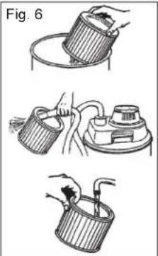
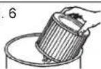
Clean the filter (Fig. 6):
-
Clean a dry filter cartridge by by tapping the filter cartridge on the inside of a waste container or by blowing loose dirt using exhaust port.
-
Clean a wet filter cartridge by rinsing it from the inside. Make sure that the filter is dry before using it to pick up dry material. When wet (to prevent mold and/or mildew build-up), the cartridge filter should be removed and allowed to air dry for a 24-hour period before being re-installed on the filter cage.
-
Slide clean cartridge filter over filter cage (Fig. 7).
-
Place filter retainer on top of cartridge filter.
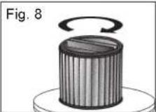
- Hold onto base of lid cage with one hand and turn retainer clockwise to tighten (Fig. 8).
natural_image
Three-step illustration of a hand using a tool to lift a cup, showing different mechanical setups (no text or symbols)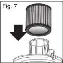

WARNING!
To reduce the risk of injury, always unplug the tool before removing the motor head.
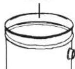
Installing and cleaning foam filters
- Unplug vacuum cleaner.
- Remove motor head.
Caution: Use care when handling motor head. Dropping motor head may cause permanent damage.
- Remove the foam filter sleeve (and cloth filter if present) from motor head.
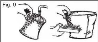
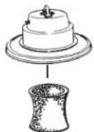
- Clean the foam filter sleeve by rinsing it from the inside. Make sure that the filter is dry before using it to pick up dry material. Clean cloth filters by shaking off loose material and brushing the filter with a soft bristle brush (Fig. 9).
- Attach the clean foam filter sleeve to motor head (Fig. 10).
• If you plan to vacuum dry material into a filter bag, expand the paper filter bag and fit cardboard collar onto the intake tube as far as possible.
- If you plan to vacuum dry material and you are using the foam filter sleeve, you must also use the cloth filter.
- Replace motor head and snap down tank latches.
natural_image
Illustration of two hands performing a manual task: one handling a container with contents, the other handling a tray with contents (no text or symbols)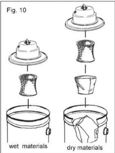
OPERATION
Vacuuming wet or dry materials (Fig. 11)
When vacuuming dry materials, either the filter cartridge or the foam filter sleeve AND the cloth filter are required. There are other filters that can be used with the required filters to provide additional filtration when vacuuming dry material. Follow the instructions included with these filters. Empty tank and clean filter frequently. Be sure filters are dry before using the vacuum to pick up dry material. Dry material will clog wet filters and make them difficult to clean.
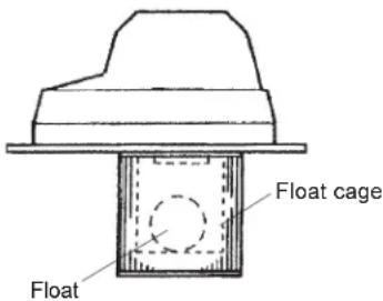
When vacuuming wet materials, either the filter cartridge or a foam filter sleeve is required. A float valve shuts off suction when the tank is full. Be sure that the float is clean and moves freely in the float cage to ensure that the float valve works. If you are vacuuming a large amount of liquid, the filter cartridge can become saturated and a mist can appear from the exhaust port. If this happens, dry the filter by running the vacuum (without picking up anything) for 10 minutes.
Fig. 11

WARNING!
If the float is clean and moves freely and the suction does not shut off when tank is filled (you will be able to see water in the exhaust port), send motorhead to the nearest MILWAUKEE service facility for repair.
Starting and Stopping the Vacuum
To turn vacuum cleaner on, switch the ON/OFF switch to the ON position.
To turn vacuum cleaner off, switch the ON/OFF switch to the OFF position.
For Cat. No. 8936-20:
To turn vacuum on, set the AUTO/OFF/ON switch to ON position.
To turn vacuum off, set the AUTO/OFF/ON switch to the OFF position. To turn the vacuum on automatically by using a tool plugged into the outlet on the motor head, set the AUTO/OFF/ON switch to the AUTO position.
Removing liquid from the vacuum tank
- Unplug vacuum cleaner.
- Remove motor head and set aside.
- Block wheels.
- Carefully dump contents into floor drain. Do not dump through intake tube.
- Rinse and dry tank.
Do not store vacuum cleaner with liquid in tank. Run the vacuum for about 10 minutes without picking up anything to dry the inside of the tank and the filter cartridge.
Using the vacuum as a blower (Cat. Nos. 8950 & 8955 only)

WARNING!
To reduce the risk of injury: wear safety glasses and a dustmask when using the vacuum cleaner as a blower.
Attach hose to exhaust port on the motor head, attach the appropriate accessory to the hose, turn the vacuum on.
Using the vacuum cleaner to collect dust created by tools
Many tools (such as sanders) are designed so that they can be used with vacuum cleaners. The vacuum cleaners collect the dust that these tools create before it gets into the air or onto the floor. Vacuum cleaners with the AUTO setting are ideal for collecting dust because they can be set up to turn on and off automatically by using the tool's on and off switch. Vacuum cleaners without an AUTO setting can also be used to collect dust. The operator will simply have to turn the vacuum on and off.
Using the vacuums (without the automatic switch) as dust collection device for a tool
- Connect vacuum hose to tool's dust collection port.
- Turn the vacuum cleaner on.
- Turn on tool.
To use the vacuum cleaner as an automatic dust collection device for a tool (with Cat. No. 8936-20 only)

WARNING!
To reduce the risk of fire, electric shock or injury: Do not plug any tool or appliance rated over 8 amps into the outlet on the vacuum cleaner. Check nameplate of the tool for the amp rating. To reduce the risk of injury, tool must be turned off before placing switch in the auto position.
- Connect vacuum hose to tool.
- With the power switch in the "O" (Off) position, plug power cord of the tool (also turned off) into the electrical outlet on the vacuum cleaner's motor head.
- Set the AUTO/OFF/ON switch to AUTO. A very brief running operation of the vacuum will occur. This is normal. Now the vacuum will operate "On Demand".
- Turn tool on and the vacuum cleaner will start automatically a few seconds later. Turn tool off and vacuum will stop automatically a few seconds later.
Utility Outlet Load - vs - Vacuum Performance
The unique design of the "On Demand" feature of this unit will cause the vacuum performance to vary with the amount of current drawn from the utility outlet. The electronic circuit automatically adjusts the power of the vacuum unit to compensate for the power being drawn from the utility outlet. This adjustment allows the total system current draw to stay within the safety regulatory agencies maximum of 12 Amps. What ever the amount of current is being drawn for utility work, the remainder from 12 Amps is allowed to the vacuum unit to provide the maximum allowable vacuum performance during the work. As soon as the utility work stops, the vacuum returns to full power during the delay period before turning off.
MAINTENANCE

WARNING!
To reduce the risk of injury, always unplug your tool before performing any maintenance. Never disassemble the tool or try to do any rewiring on the tool's electrical system. Contact a MILWAUKEE service facility for ALL repairs.
Maintaining Tools
Keep your tool in good repair by adopting a regular maintenance program. Before use, examine the general condition of your tool. Inspect guards, switches, tool cord set and extension cord for damage. Check for loose screws, misalignment, binding of moving parts, improper mounting, broken parts and any other condition that may affect its safe operation. If abnormal noise or vibration occurs, turn the tool off immediately and have the problem corrected before further use. Do not use a damaged tool. Tag damaged tools "DO NOT USE" until repaired (see "Repairs").
Under normal conditions, relubrication is not necessary until the motor brushes need to be replaced. After six months to one year, depending on use, return your tool to the nearest MILWAUKEE service facility for the following:
- Lubrication
- Brush inspection and replacement
- Mechanical inspection and cleaning (gears, spindles, bearings, housing, etc.)
• Electrical inspection (switch, cord, armature, etc.) - Testing to assure proper mechanical and electrical operation

WARNING!
To reduce the risk of injury, electric shock and damage to the tool, never immerse your tool in liquid or allow a liquid to flow inside the tool.
Cleaning
Clean dust and debris from vents. Keep the tool handles clean, dry and free of oil or grease. Use only mild soap and a damp cloth to clean your tool since certain cleaning agents and solvents are harmful to plastics and other insulated parts. Some of these include: gasoline, turpentine, lacquer thinner, paint thinner, chlorinated cleaning solvents, ammonia and household detergents containing ammonia. Never use flammable or combustible solvents around tools.
Repairs
If your tool is damaged, return the entire tool to the nearest service center.
ACCESSORIES

WARNING!
To reduce the risk of injury, always unplug the tool before attaching or removing accessories. Use only specifically recommended accessories. Others may be hazardous.
For a complete listing of accessories refer to your MILWAUKEE Electric Tool catalog or go on-line to www.milwaukeetool.com. To obtain a catalog, contact your local distributor or a service center.
FIVE YEAR TOOL LIMITED WARRANTY
Every MILWAUKEE tool is tested before leaving the factory and is warranted to be free from defects in material and workmanship. MILWAUKEE will repair or replace (at MILWAUKEE's discretion), without charge, any tool (including battery chargers) which examination proves to be defective in material or workmanship from five (5) years after the date of purchase. Return the tool and a copy of the purchase receipt or other proof of purchase to a MILWAUKEE Factory Service/Sales Support Branch location or MILWAUKEE Authorized Service Station, freight prepaid and insured. This warranty does not cover damage from repairs made or attempted by other than MILWAUKEE authorized personnel, abuse, normal wear and tear, lack of maintenance, or accidents.
Battery Packs, Flashlights, and Radios are warranted for one (1) year from the date of purchase.
THE REPAIR AND REPLACEMENT REMEDIES DESCRIBED HEREIN ARE EXCLUSIVE. IN NO EVENT SHALL MILWAUKEE BE LIABLE FOR ANY INCIDENTAL, SPECIAL, OR CONSEQUENTIAL DAMAGES, INCLUDING LOSS OF PROFITS.
THIS WARRANTY IS EXCLUSIVE AND IN LIEU OF ALL OTHER WARRANTIES, OR CONDITIONS, WRITTEN OR ORAL, EXPRESSED OR IMPLIED FOR MERCHANTABILITY OR FITNESS FOR PARTICULAR USE OR PURPOSE.
This warranty gives you specific legal rights. You may also have other rights that vary from state to state and province to province. In those states that do not allow the exclusion of implied warranties or limitation of incidental or consequential damages, the above limitations or exclusions may not apply to you. This warranty applies to the United States, Canada, and Mexico only.

AVERTISSEMENT!
VOUS DEVEZ LIRE ET COMPRENDRE TOUTES LES INSTRUCTIONS.
LISEZ ATTENTIVEMENT CES INSTRUCTIONS
| Underwriters Laboratories, Inc. | |
| Canadian Standards Association | |
| Hz | Hertz |
| A | Amperes |
Specifications
natural_image
Close-up of a black vacuum cleaner with labeled component (6), no visible text or symbols on the device itself.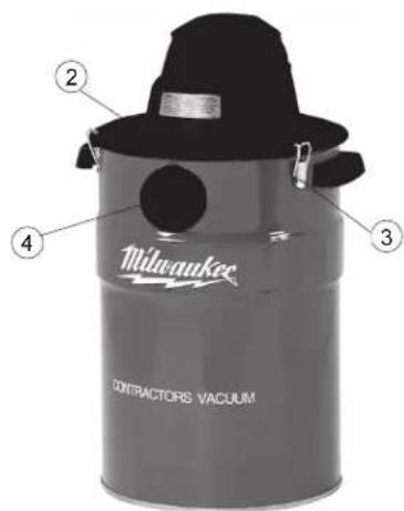

MISE À LA TERRE

AVERTISSEMENT!
natural_image
Electrical socket and socket assembly diagram (no text or symbols)natural_image
Three-step illustration of a hand using a tool to clean or adjust a container (no text or symbols present)natural_image
Illustration of two hands performing a manual task: one handling a bag, the other handling a container (no text or symbols)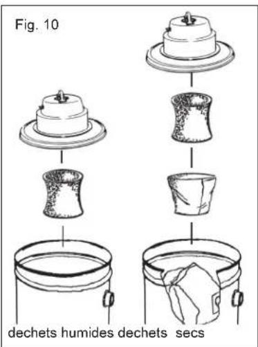
| Underwriters Laboratories, Inc. | |
| Canadian Standards Association | |
| Hz | Hertz |
| A | Amperios |
Specifications
natural_image
Close-up of a black vacuum cleaner with labeled component (6), no visible text or symbols on the device itself.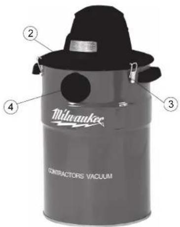
TIERRA

¡ADVERTENCIA!
natural_image
Diagram of a cylindrical component with an arrow pointing upward, no text or symbols presentFig. 6

natural_image
Illustration of two hands performing a manual task: one handling a container with a tool, the other handling a tray with a brush (no text or symbols present)Fig. 10
materiales
humedos
materiales
secos
MILWAUKEE prides itself in producing a premium quality product that is NOTHING BUT HEAVY DUTY®.
Your satisfaction with our products is very important to us!
If you encounter any problems with the operation of this tool, or you would like to locate the factory Service/Sales Support Branch or authorized service station nearest you, please call...
1-800-SAWDUST
(1.800.729.3878)
NATIONWIDE TOLL FREE
Monday-Friday • 8:00 AM - 4:30 PM • Central Time or visit our website at
www.milwaukeetool.com
For service information, use the 'Service Center Search' icon found in the 'Parts & Service' section.
Additionally, we have a nationwide network of authorized Distributors ready to assist you with your tool and accessory needs. Check your "Yellow Pages" phone directory under "Tools-Electric" for the names & addresses of those nearest you or see the 'Where To Buy' section of our website.
Corporate After Sales Service - Technical Support Brookfield, Wisconsin USA
•Technical Questions •Service/Repair Questions •Warranty
1-800-SAWDUST
(1.800.729.3878)
fax:1.800.638.9582
email: metproductsupport@milwaukeeetool.com
Monday-Friday • 8:00 AM - 4:30 PM • Central Time
CANADA
Service MILWAUKEE
Milwaukee Electric Tool (Canada) Ltd
755 Progress Avenue
Scarborough, Ontario M1H 2W7
Milwaukee Electric Tool, S.A. de C.V.
Blvd. Abraham Lincoln no. 13
Colonia Los Reyes Zona Industrial
Tlalnepantla, Edo. México C.P. 54073
Tel. (55) 5565-1414 Fax: (55) 5565-6874
MILWAUKEE ELECTRIC TOOL CORPORATION
13135 West Lisbon Road • Brookfield, Wisconsin, U.S.A. 53005

- HEAVY-DUTY COMMERCIAL VACUUM EXTRA ROBUSTE ASPIRATEUR COMMERCIAL HEAVY-DUTY ASPIRADORA COMMERCIAL
- GENERAL SAFETY RULES
- WARNING!
- READ AND UNDERSTAND ALL INSTRUCTIONS
- SAVE THESE INSTRUCTIONS
- READ AND SAVE ALL INSTRUCTIONS FOR FUTURE USE.
- FUNCTIONAL DESCRIPTION
- GROUNDING EXTENSION CORDS
- Grounded Tools:
- Tools with Three Prong Plugs
- Double Insulated Tools:
- Tools with Two Prong Plugs
- Guidelines for Using Extension Cords
- TOOL ASSEMBLY
- Assembling Dolly (Cat. No. 8955) (Fig. 1)
- Installing Handle (Cat. No. 8955) (Fig. 2)
- Assembling Dolly (Cat. No. 8938-20) (Fig. 3)
- Attaching Caddy and Casters (Cat. No. 8936-20)
- Installing and cleaning Cartridge Filters
- Installing and cleaning foam filters
- OPERATION
- Vacuuming wet or dry materials (Fig. 11)
- Starting and Stopping the Vacuum
- Removing liquid from the vacuum tank
- Using the vacuum cleaner to collect dust created by tools
- Using the vacuums (without the automatic switch) as dust collection device for a tool
- Utility Outlet Load - vs - Vacuum Performance
- MAINTENANCE
- Maintaining Tools
- Cleaning
- Repairs
- ACCESSORIES
- FIVE YEAR TOOL LIMITED WARRANTY
- AVERTISSEMENT!
- VOUS DEVEZ LIRE ET COMPRENDRE TOUTES LES INSTRUCTIONS.
- MISE À LA TERRE
- TIERRA
- ¡ADVERTENCIA!
- 1-800-SAWDUST
- www.milwaukeetool.com
- CANADA
- Service MILWAUKEE
- MILWAUKEE ELECTRIC TOOL CORPORATION
Brand : MILWAUKEE
Model : 893620
Category : Vacuum Cleaner