
48228553 - Workbench MILWAUKEE - Free user manual and instructions
Find the device manual for free 48228553 MILWAUKEE in PDF.

| Product Type | Rolling Workbench with Storage |
| Brand | Milwaukee |
| Model | 48228553 (48-22-8553) |
| Dimensions (approx.) | Approximately 180 x 90 x 100 cm (estimate based on capacity) |
| Weight | Approximately 150 kg (estimate) |
| Power Supply | 120 V AC, 60 Hz, 15 A |
| USB Ports | 2 USB ports (5 V, 10.5 W, 2.1 A max each) |
| Total Load Capacity | 816.5 kg (1800 lbs) |
| Drawer Capacity | 45.4 kg (two-slide drawer) / 90.7 kg (four-slide drawer) |
| Operating Temperature | -18 °C to 40 °C |
| Material | Powder-coated steel, wood work surface |
| Wheels | 2 swivel casters with brake, 2 rigid casters |
| Locking System | Central key for all drawers and surface |
| Main Features | Work surface, storage, power strip, USB ports, charger bracket, side shelf, bottle opener, tool suspension |
| Maintenance | Clean with mild detergent and water; lubricate slides every 6 months and casters annually |
| Compliance | FCC Part 15 Class B |
| Warranty | 3 years (parts and labor) |
| Included Accessories | Side handle, bumpers, cord storage hooks, tool suspension, storage shelf, bottle opener, key, tool organizer |
| Repairability | Spare parts available from Milwaukee after-sales service |
Frequently Asked Questions - 48228553 MILWAUKEE
User questions about 48228553 MILWAUKEE
0 question about this device. Answer the ones you know or ask your own.
Ask a new question about this device
Download the instructions for your Workbench in PDF format for free! Find your manual 48228553 - MILWAUKEE and take your electronic device back in hand. On this page are published all the documents necessary for the use of your device. 48228553 by MILWAUKEE.
USER MANUAL 48228553 MILWAUKEE
natural_image
Line drawing of a Milwaukee industrial cart with wheels and side panels (no text or symbols on the cart itself)Cat. No. / No de cat.
48-22-8553
52" HIGH CAPACITY MOBILE WORK BENCH BANC DE TRAVAIL MOBILE GRANDE CAPACITÉ DE 1,32 m (52") BANCO DE TRABAJO MÓVIL ALTA CAPACIDAD DE 1,32 m (52")

WARNING To reduce the risk of injury, user must read and understand operator's manual.
IMPORTANT SAFETY INSTRUCTIONS
WARNING
Read all safety warnings and all instructions. Failure to follow the warnings and instructions may result in serious injury. Save all warnings and instructions for future reference.
- Use the station and accessories in accordance with these instructions and in the manner intended, taking into account the working conditions. Use of the station for operations different from those intended could result in a hazardous situation.
- Keep work area clean and well lit. Cluttered or dark areas invite accidents.
- Fully assemble the station according to the assembly instructions. Do not leave off any pieces.
- Do not modify the station in any way. Use only specifically recommended accessories. Drilling holes or modifying the station will lower the load capacity, which can cause the station to collapse, resulting in injury.
- Lock wheels when station is not being moved. Unlocked wheels can allow the station to move unexpectedly.
- Keep the station on a level surface. Do not load, unload, or park station on an incline. The station may become unbalanced and tip, resulting in injury.
- Always balance the station load to avoid tipping. Unbalanced stations are more likely to tip when being moved or when using the station work surfaces. Evenly distribute the weight front to back and side to side. To help prevent the station from tipping, load the product starting with the bottom drawers.
- Do not exceed the maximum product weight, including contents. Do not exceed the maximum weight for each drawer. Overloaded stations can tip, collapse, or damage drawer slides.
- Do not open more than one drawer at a time. Station may tip, causing injury.
- Keep children and bystanders away while loading, unloading, and moving the station. Distractions can cause you to lose control.
- Only lift the station according to the instructions in this manual. Never lift by the side handle. Other methods may be dangerous, resulting in injury.
- Only transport the station when empty. Properly secure when transporting.
- Do not mount the station on a truck bed or any other moving object.
- Lock all drawers before rolling the station. The drawers could come open and make the station unstable and tip.
- Only roll the station short distances by using the handle provided.
- Secure all items before rolling the station. Loose items could shift, causing the station to become unstable.
- Do not use drawers as steps. Do not stand on the station. Station may tip, causing injury.
- Do not step on side shelf. Shelf may collapse or break. Station may tip, causing injury.
- Do not use station in explosive atmospheres, such as in the presence of flammable liquids, gases or dust. This equipment has internal arcing or sparking parts. Station should not be located in a recessed area or below floor level.
- Station plugs must match the outlet. Never modify the plug in any way. Do not use any adapter plugs with earth (grounded) chest/cabinet power strips. Unmodified plugs and matching outlets will reduce risk of electric shock.
- Avoid body contact with earthed or grounded surfaces such as pipes, radiators, ranges and refrigerators. There is an increased risk of electric shock if your body is earthed or grounded.
- Maintain station. Check for misalignment or binding wheels, breakage or bending of drawer slides or other parts and any other condition that may affect the station's operation. Do not use damaged station.
- Maintain labels and nameplates. These carry important information. If unreadable or missing, contact a MILWAUKEE service facility for a free replacement.
- Have your station serviced by a qualified repair person using only identical replacement parts. This will ensure that the safety of the station is maintained.
Federal Communications Commission
WARNING: Changes or modifications to this unit not expressly approved by the party responsible for compliance could void the user's authority to operate the equipment.
This device complies with Part 15 of the FCC Rules. Operation is subject to the following two conditions: (1) this device may not cause harmful interference, and (2) this device must accept any interference received, including interference that may cause undesired operation.
NOTE: This equipment has been tested and found to comply with the limits for a Class B digital device, pursuant to Part 15 of the FCC Rules. These limits are designed to provide reasonable protection against harmful interference in a residential installation. This equipment generates, uses and can radiate radio frequency energy and, if not installed and used in accordance with the instructions, may cause harmful interference to radio communications. However, there is no guarantee that interference will not occur in a particular installation. If this equipment does cause harmful interference to radio or television reception, which can be determined by turning the equipment off and on, the user is encouraged to try to correct the interference by one or more of the following measures:
- Reorient or relocate the receiving antenna.
- Increase the separation between the equipment and receiver.
- Connect the equipment into an outlet on a circuit different from that to which the receiver is connected.
- Consult the dealer or an experienced radio/TV technician for help.
GROUNDING
⚠WARNING Improperly connecting the grounding wire can result in the risk of electric shock. Check with a qualified electrician if you are in doubt as to whether the outlet properly grounded. Do not modify the plug provided with the station. Never remove the grounding prong from the plug. Do not use the station if the cord or plug is damaged. If damaged, have it repaired before use. If the plug will not fit the outlet, have a proper outlet installed by a qualified electrician.
Stations with Three Prong Plugs
Stations marked "Grounding Required" have a power strip with a three wire cord and three prong grounding plug. The plug must be connected to a properly grounded outlet (See Figure A). If the power strip should electrically malfunction or break down, grounding provides a low resistance path to carry electricity away from the user, reducing the risk of electric shock. The grounding prong in the plug is connected through the green wire inside the cord to the grounding system in the power strip. The green w must be the only wire connected to the grounding system and must never be electrically "live" terminal.
Your power strip must be plugged into an appropriate outlet, properly installed and grounded in accordance with all codes and ordinances. The plug and outlet should look like those in Figure A.
SYMBOLOGY

ning

nd Operator's Manual

Electrical Shock Hazard

not open more than one drawer at a e. Station may tip, causing injury.

k wheels when station is not being ved. Unlocked wheels can allow the ion to move unexpectedly.

Do not use drawers as steps. Station tip, causing injury.

Lock all drawers before moving the station.

Do not step on side shelf. Shelf may lapse or break. Station may tip, causing injury.
SPECIFICATIONS
Cat. No. 48-22-8553
Two-Slide Drawer Capacity .....100 lbs. (45.4 kg)
Four-Slide Drawer Capacity .....200 lbs. (90.7 kg)
i\$otal Capacity....1800 lbs. (816.5 kg)
AC Input Volts....120
Hertz....60
Amps 15
USB Output Volts....5
USB Watts 10.5
USB Amps 2.1
Recommended Ambient Operating
Temperature .....0°F to 104°F (-18°C to 40°C)
FUNCTIONAL DESCRIPTION
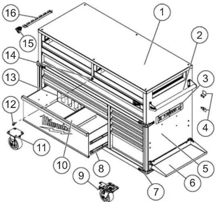
- Wood work surface
- Side handle
- Power strip with USB ports
- Cord storage brackets
- Charger mounts
- Storage shelf
- Bumper
-
Drawer slide
-
Swivel caster with brake
- Drawer divider
- Rigid caster
12.Key - Tool organizer
- Lock
- Bottle opener
- Tool hanger
ASSEMBLY
CAUTION Be sure to follow the assembly instructions for the appropriate station. Do not use power tools to assemble station. Tighten bolts with hand wrenches.
Tools Required
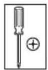
Phillips
screwdriver
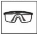
Safety goggles
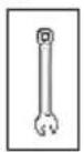
10 mm Wrench
13 mm Wrench
Hardware Included
NOTE: Items not shown to actual size.
| Hardware Item Description Quantity | |||
| AA Bolt | N 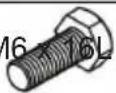 | 10 | |
| BB |  | Screw M4 x 16L | 12 |
| CC |  | Screw M4 x 12L | 8 |
| DD |  | Nylon washer 19 x 8.5 x 1.5 | 2 |
| EE |  | Nut M6 2 | |
| FF |  | Shoulder bolt M6 x 8L | 2 |
| GG |  | Screw M6 x 16L | 2 |
| Item Description Quantity | ||
 | Side handle 1 | |
 | Front bumper 4 | |
 | Rear bumper 2 | |
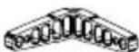
| [44X6] | Cabinet corner extrusion | 2 |
 | Cord Storage Bracket | 2 |
| [1TBW] | Tool hanger 1 | |
 | Shelf hinge bracket 2 | |
| [SZY2] | Bottle opener 1 | |
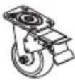 | Swivel caster with brake | 2 |
 | Rigid caster 2 | |
NOTE: Begin product assembly close to the final intended location of your station. This product is heavy and may be difficult to move after assembly.
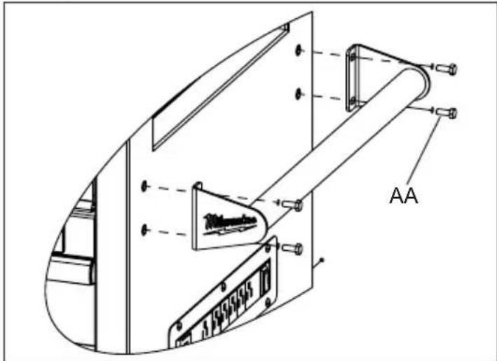
Attaching the Side Handle
Attach the side handle to the station using four bolts (AA). The side handle can be attached to either side of the station.
NOTE: The holes in the station are tapped and do not require nuts.
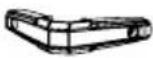
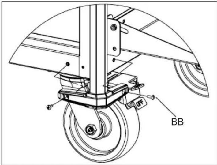
Installing the Corner Extrusions and Bumpers
Place the front bumpers on both ends of the extrusion by sliding the extrusion into the cavity of the bumpers. Attach the front bumpers with extrusions using two screws (BB) per bumper.
Attach the two rear bumpers to the back of the lower cabinet using two screws (BB) per bumper.
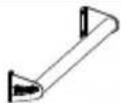
Installing the Cord Storage Brackets
Attach the brackets to the station with two screws (CC) per bracket. Orient the brackets with one pointed up and one pointed down so that the power outlet cord can be wrapped around the brackets for storage.
Attaching the Tool Hanger
Attach the tool hanger to the left end of the station using two bolts (AA).
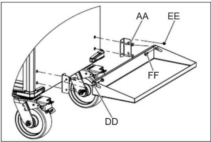
Installing the Storage Shelf
Attach the shelf hinge brackets to the right cabinet using two bolts (AA) for each bracket. Attach the storage shelf to the brackets using one washer (DD), nut (EE) and bolt (FF) on each end.
Reversing the Wood Work Surface
The wood work surface comes pre-installed with the station. After wear and tear, the surface may be reversed to use the clean bottom surface. To reverse, remove the six screws from the top of the wood work surface, flip surface, and reinstall the six screws.
Installing the Bottle Opener
Attach the bottle opener to the left side of the cabinet using two screws (GG).
USB Power Outlet
The USB ports on the power outlet can be used to charge any device that uses less than 2.1 A of DC electrical current.
NOTE: Any device that uses more than 2.1 A of DC electrical current will trip a self-resetting overload and disable the output.
Installing the Drawer Liners
Place the drawer liners in appropriately sized drawers to protect the surface.
OPERATION
⚠ WARNING To avoid injury or property damage, do not exceed maximum drawer capacity. Use care when moving the station on incline or rough surface. Station may tip if weight is not evenly distributed front to back and side to side. Place more than half the total load weight on the bottom drawers when possible.
Locking and Unlocking the Station NOTE: The drawers must be fully closed before locking/unlocking the unit.
Insert the key. Turn it fully left to lock, or fully right to unlock. Always remove the key after locking and unlocking.
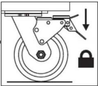
Using the Caster Brakes
To lock the swivel casters, step down on the levers marked ON. Be sure to lock all casters to prevent station from rolling or swiveling. To unlock casters, push down on the levers marked OFF.
Moving the Station on an Incline or Rough Surface
Take care that the station does not tip or become unbalanced when moving it on an incline or rough surface. Do not exceed an incline of 10 degrees. Lock the station and secure all items before moving.
Rolling the Station
The station is only intended for rolling short distances. Only roll the station using the handle. Do not push or pull station by the frame or product may tip. Do not modify the station in any way. Drilling holes or modifying the station will lower the load capacity, which can cause the station to collapse, resulting in injury. Lock the station and secure all items before rolling.
Lifting the Station
The station is not intended to be lifted. However, if you need to lift, empty the station and then place straps or forks inside and next to casters. Do not lift loaded stations. Never lift by the side handle. Be sure all bystanders are moved away before lifting station.
Mounting Chargers
The station comes equipped with four pre-installed charger mounting bosses, located below the power strip. The charger mounts are suitable for holding MILWAUKEE M18 ^TM & M12 ^TM Multi Voltage chargers as well as M18 ^TM chargers. To mount a charger, install a screw (CC) into each boss, then slide the charger's key-hole slots over the screws. Slide the charger toward the floor to lock it onto the screws.
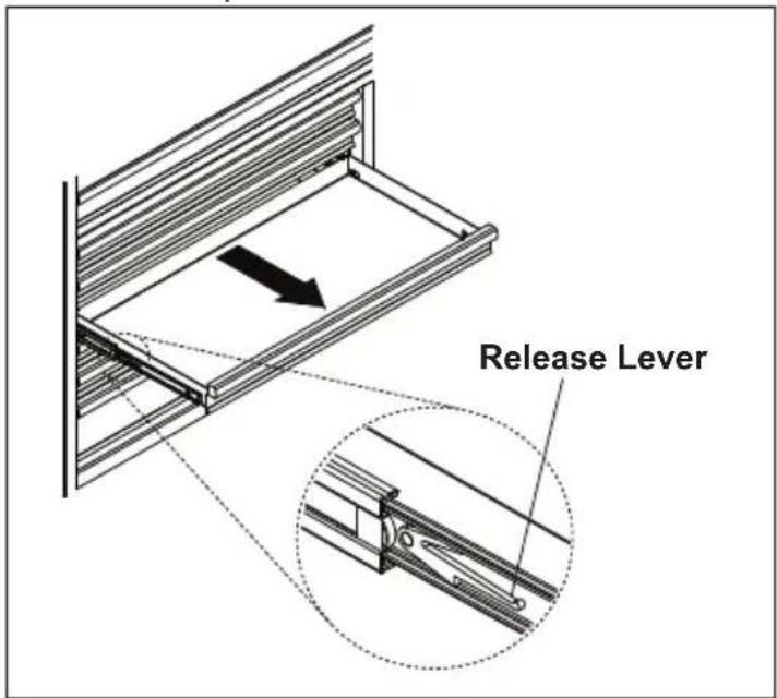
Removing the Drawers
- Fully extend and empty the drawer.
- Depending on the side, either lift or lower the release lever on both sides so the slides can ride over the stops. Pull out to remove.
Installing the Drawers
- Pull the slides and slide carrier out until fully extended.
- Hold the slide on the cabinet while aligning it with the slide on the drawer.
- Slightly insert one side and repeat for the other side.
- Slowly push the drawer until it is fully closed to engage the slide.
- Open and close the drawer to verify proper operation.
MAINTENANCE
WARNING To reduce the risk of injury, contact MILWAUKEE Corporate After Sales Service Technical Support for ALL repairs and replacement parts.
Maintaining the Station
Keep your station in good repair by adopting a regular maintenance program. Before use, examine the general condition of your station. Check for loose screws, misalignment, binding of wheels, broken parts and any other condition that may affect its safe operation. Do not use a damaged station.
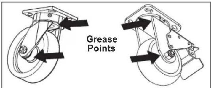
Maintaining the Casters
Grease the casters annually using high quality bearing grease.
Maintaining the Drawers
- Periodically clean the drawer with a mild detergent and water.
- Remove grease and oil in drawer with a standard, nonflammable cleaning fluid.
- The use of drawer liners is recommended to protect the finish inside the drawers and ma the drawers easier to clean. Drawer liners can be cleaned with soap and water.
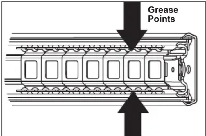
- Lubricate the slides semi-annually with general purpose grease or equivalent.
Cleaning
This steel product has been coated with industrial powder coating for a durable finish. To help protect the powder coated finish, do not allow harsh chemicals (oil, grease or other chemical) to remain on the powder coating surface. Use a glass cleaner to clean and maintain all surfaces of powder coating. Keep the station handles and wheels clean, dry and free of oil or grease. Use only mild soap and a damp cloth to clean your station since certain cleaning agents and solvents are harmful to plastics. Some of these include: gasoline, turpentine, lacquer thinner, chlorinated cleaning solvents, ammonia and household detergents containing ammonia. Never use flammable or combustible solvents around station.
Service
For service and repair information, including the ordering of service parts, call our Corporate After Sales Service Technical Support line at 1-800-SAWDUST, or visit our website at www.milwaukeeetool.com.
ACCESSORIES
WARNING Modifying the station to accept other accessories may be hazardous, resulting in injury or property damage. Use only specifically recommended accessories according to the manufacturer's instructions.
For a complete listing of accessories, go online to www.milwaukeetool.com or contact a distributor.
SERVICE - UNITED STATES
1-800-SAWDUST (1.800.729.3878)
Monday-Friday, 7:00 AM - 6:30 PM CST
or visit www.milwaukeetool.com
Contact Corporate After Sales Service Technical Support with technical, service/repair, or warranty questions.
Email: metproductsupport@milwaukeeetool.com
Become a Heavy Duty Club Member at www.milwaukeetool.com to receive important notifications regarding your tool purchases.
SERVICE - CANADA
Milwaukee Tool (Canada) Ltd
1.800.268.4015
Monday-Friday, 7:00 AM - 4:30 PM CST
or visit www.milwaukeetool.ca
LIMITED WARRANTY USA & CANADA
Every MILWAUKEE steel storage chest and cabinet are warranted to the original purchaser only to be free from defects in material and workmanship. Subject to certain exceptions, MILWAUKEE will repair or replace any part on a chest or cabinet which, after examination, is determined by MILWAUKEE to be defective in material or workmanship for a period of three (3) years after the date of purchase. Return of the chest or cabinet to the place of purchase is required. A copy of the proof of purchase should be included with the return product. This warranty does not apply to damage that MILWAUKEE determines to be from repairs made or attempted by anyone other than MILWAUKEE authorized personnel, misuse, alterations, abuse, normal wear and tear, lack of maintenance, or accidents.
Warranty Registration is not necessary to obtain the applicable warranty on a MILWAUKEE steel storage chest or cabinet. The manufacturing date of the product will be used to determine the warranty period if no proof of purchase is provided at the time warranty service is requested. If you feel your product has a warranty defect, or if you need information on a service/replacement part, please contact MILWAUKEE at 1.800. SAWDUST (1.800.729.3878) for instructions.
ACCEPTANCE OF THE EXCLUSIVE REPAIR AND REPLACEMENT REMEDIES DESCRIBED HEREIN IS A CONDITION OF THE CONTRACT FOR THE PURCHASE OF EVERY MILWAUKEE PRODUCT. IF YOU DO NOT AGREE TO THIS CONDITION, YOU SHOULD NOT PURCHASE THE PRODUCT. IN NO EVENT SHALL MILWAUKEE BE LIABLE FOR ANY INCIDENTAL, SPECIAL, CONSEQUENTIAL OR PUNITIVE DAMAGES, OR FOR ANY COSTS, ATTORNEY FEES, EXPENSES, LOSSES OR DELAYS ALLEGED TO BE AS A CONSEQUENCE OF ANY DAMAGE TO, FAILURE OF, OR DEFECT IN ANY PRODUCT INCLUDING, BUT NOT LIMITED TO, ANY CLAIMS FOR LOSS OF PROFITS. SOME STATES DO NOT ALLOW THE EXCLUSION OR LIMITATION OF INCIDENTAL OR CONSEQUENTIAL DAMAGES, SO THE ABOVE LIMITATION OR EXCLUSION MAY NOT APPLY TO YOU. THIS WARRANTY IS EXCLUSIVE AND IN LIEU OF ALL OTHER EXPRESS WARRANTIES, WRITTEN OR ORAL. TO THE EXTENT PERMITTED BY LAW, MILWAUKEE DISCLAIMS ANY IMPLIED WARRANTIES, INCLUDING WITHOUT LIMITATION ANY IMPLIED WARRANTY OF MERCHANTABILITY OR FITNESS FOR A PARTICULAR USE OR PURPOSE; TO THE EXTENT SUCH DISCLAIMER IS NOT PERMITTED BY LAW, SUCH IMPLIED WARRANTIES ARE LIMITED TO THE DURATION OF THE APPLICABLE EXPRESS WARRANTY AS DESCRIBED ABOVE. SOME STATES DO NOT ALLOW LIMITATIONS ON HOW LONG AN IMPLIED WARRANTY LASTS, SO THE ABOVE LIMITATION MAY NOT APPLY TO YOU, THIS WARRANTY GIVES YOU SPECIFIC LEGAL RIGHTS, AND YOU MAY ALSO HAVE OTHER RIGHTS WHICH VARY FROM STATE TO STATE. This warranty applies to product sold in the U.S.A. and Canada only. Please consult the 'Find a Service Center Search' in the Parts & Service section of MILWAUKEE's website www.milwaukeeetool.com or call 1.800.SAWDUST (1.800.729.3878) to locate your nearest MILWAUKEE factory Service Center location.
INSTRUCTIONS IMPORTANTES CONCERNANT LA SÉCURITÉ
AVERTISSEMENT
Federal Communications Commission
natural_image
Mechanical diagram showing a wheel with a lock and directional arrow (no text or symbols)Milwaukee Tool (Canada) Ltd 1.800.268.4015
Monday-Friday, 7:00 AM - 4:30 PM CST
www.milwaukeetool.ca
GARANTIE LIMITÉE - AUX ÉTATS-UNIS ET AU CANADA
Federal Communications Commission
Lunes a Viernes (9am a 6pm)
NUEVO LEON, C.P. 66267
Tel/Phone 01 800 00 46633
- IMPORTANT SAFETY INSTRUCTIONS
- WARNING
- Federal Communications Commission
- GROUNDING
- Stations with Three Prong Plugs
- SYMBOLOGY
- SPECIFICATIONS
- FUNCTIONAL DESCRIPTION
- ASSEMBLY
- Attaching the Side Handle
- Installing the Corner Extrusions and Bumpers
- Installing the Cord Storage Brackets
- Attaching the Tool Hanger
- Installing the Storage Shelf
- Reversing the Wood Work Surface
- Installing the Bottle Opener
- USB Power Outlet
- Installing the Drawer Liners
- OPERATION
- Using the Caster Brakes
- Moving the Station on an Incline or Rough Surface
- Rolling the Station
- Lifting the Station
- Mounting Chargers
- Removing the Drawers
- Installing the Drawers
- MAINTENANCE
- Maintaining the Station
- Maintaining the Casters
- Maintaining the Drawers
- Cleaning
- Service
- ACCESSORIES
- SERVICE - UNITED STATES
- 1-800-SAWDUST (1.800.729.3878)
- SERVICE - CANADA
- Milwaukee Tool (Canada) Ltd
- 1.800.268.4015
- LIMITED WARRANTY USA & CANADA
- INSTRUCTIONS IMPORTANTES CONCERNANT LA SÉCURITÉ
- AVERTISSEMENT
- Milwaukee Tool (Canada) Ltd 1.800.268.4015
- GARANTIE LIMITÉE - AUX ÉTATS-UNIS ET AU CANADA
Brand : MILWAUKEE
Model : 48228553
Category : Workbench