WRT134TFD - Fridge WHIRLPOOL - Free user manual and instructions
Find the device manual for free WRT134TFD WHIRLPOOL in PDF.
Download the instructions for your Fridge in PDF format for free! Find your manual WRT134TFD - WHIRLPOOL and take your electronic device back in hand. On this page are published all the documents necessary for the use of your device. WRT134TFD by WHIRLPOOL.
USER MANUAL WRT134TFD WHIRLPOOL
- JUEGO DE LA FABRICA DE HIELO MODULAR2 Table of Contents Requesting Assistance or Service If you need assistance contact your dealer, or call the Whirlpool Customer eXperience Center toll-free, 1-800-253-1301, 24 hours a day. Page Page Requesting Assistance or Service p. 2
- Important Information p. 3
- Before you Begin p. 4
- Tools p. 4
- Installation notes p. 4
- Components p. 5
- Component illustrations p. 5
- Installing the Ice Maker p. 6
- Making preparations p. 6
- Side-by-side models p. 7
- Top/upright freezer models p. 9
- Installing the tubing clips p. 11
- Mounting the water valve p. 12
- Connecting the water valve tubing p. 13
- Mounting the ice maker p. 14
- Connecting the Water Supply p. 16
- Final Installation p. 18
- Installing the access cover and forming the copper tubing p. 18
- Connecting the power/ leveling the unit p. 19
- Starting the Ice Maker p. 20
- Troubleshooting p. 21
- Operational notes p. 21
- Troubleshooting chart p. 21
- Page Page Demande d’assistance oudedépannage p. 2
- Informations importantes p. 22
- Avant de commencer p. 23
- Outils p. 23
- Remarques concernant l’installation p. 23
- Composants p. 24
- Illustrations des composants p. 24
- Installation de la machine à glaçons p. 25
- Opérations préparatoires p. 25
- Modèle à compartiments juxtaposés p. 26
- Modèles à congélateur en haut/vertical p. 28
- Installation des agrafes de retenue du tube de cuivre malléable p. 30
- Montage de l’électrovanne d’admission d’eau p. 31
- Raccordement du tube de l’électrovanne d’admission d’eau p. 32
- Montage de la machine à glaçons p. 33
- Raccordement à la conduite d’eau p. 35
- Installation nale p. 37
- Installation du couvercle de l’ouverture d’accès et formage du tube de cuivre malléable p. 37
- Rétablissement de l’alimentation électrique/réglage de l’aplomb de l’appareil p. 38
- Mise en marche de la machine à glaçons p. 39
- Dépannage p. 40
- Notes sur le fonctionnement de l’appareil p. 40
- Tableau de diagnostic/dépannage p. 40
- Demande d’assistance ou de dépannage Pour tout besoin d’assistance, contacter le revendeur ou téléphoner sans frais au Centre d’eXperience à la clientèle de Whirlpool au 1-800-253-1301 (accessible 24 heures sur 24). Para solicitar ayuda o servicio técnico p. 2
- Información importante p. 41
- Antes de comenzar p. 42
- Herramientas p. 42
- Notas sobre la instalación p. 42
- Componentes p. 43
- Ilustraciones de los componentes p. 43
- Instalación de la fábrica de hielo p. 44
- Pasos de preparación p. 44
- Modelos de dos puertas p. 45
- Modelos de congelador superior/vertical p. 47
- Instalación de los clips de la tubería p. 49
- Para montar la válvula de agua p. 49
- Conexión de la tubería de la válvula de agua p. 51
- Montaje de la fábrica de hielo p. 52
- Conexión del suministro de agua p. 54
- Instalación nal p. 56
- Cómo instalar la cubierta de acceso y dar forma a la tubería de cobre p. 56
- Conexión del suministro eléctrico/nivelación de la unidad p. 57
- Puesta en marcha de la fábrica de hielo p. 58
- Solución de problemas p. 59
- Notas sobre el funcionamiento p. 59
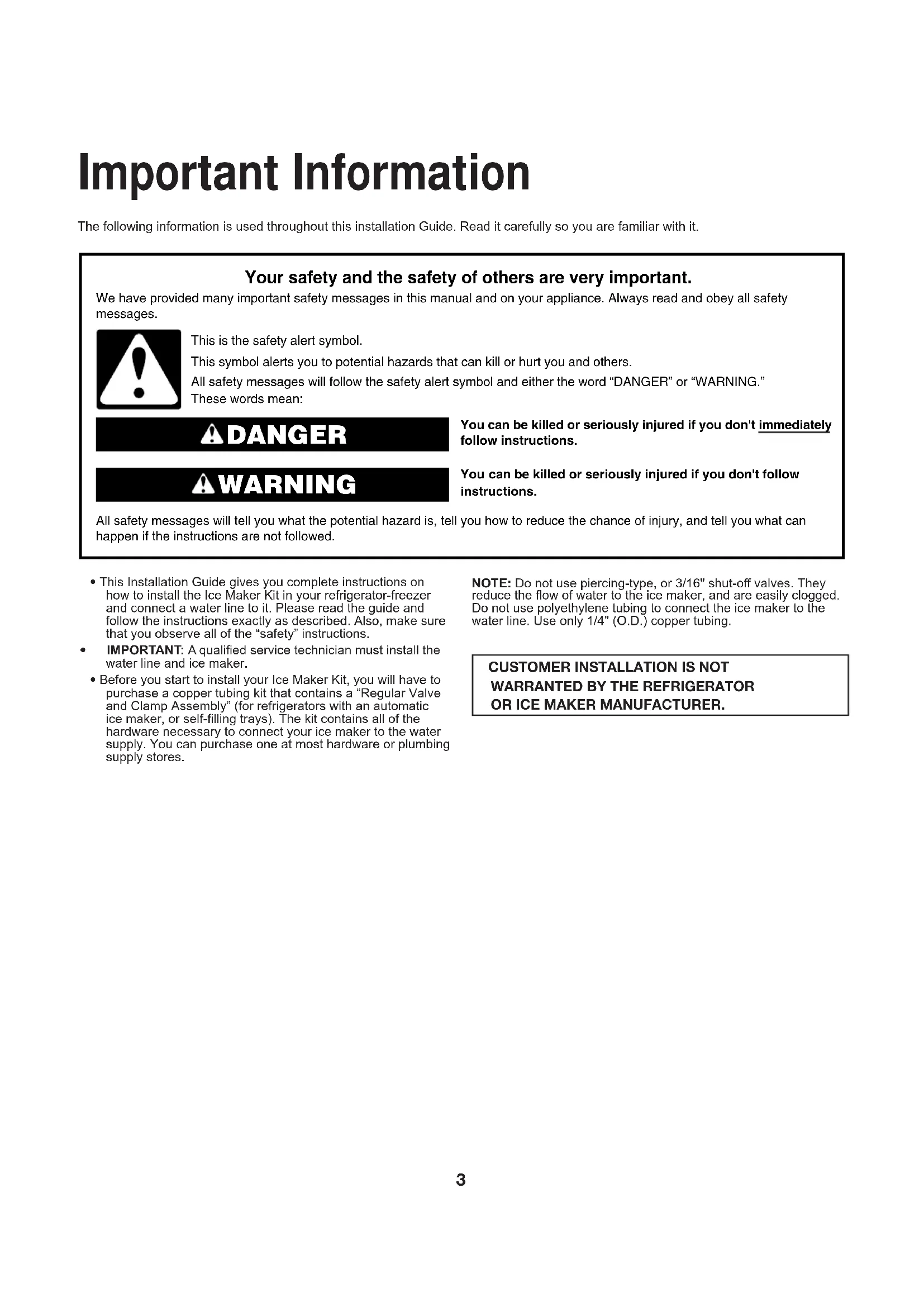
- Cuadro de solución de problemas Página Página Para solicitar ayuda o servicio técnico Si necesita ayuda, comuníquese con el distribuidor o llame sin cargo al Centro para la eXperiencia del cliente de Whirlpool, al 1-800-253-1301, las 24 horas del día. Table des matières Tabla de contenidos3 Important Information The following information is used throughout this installation Guide. Read it carefully so you are familiar with it.You can be killed or seriously injured if you don't immediately You can be killed or seriously injured if you don'tfollow All safety messages will tell you what the potential hazard is, tell you how to reduce the chance of injury, and tell you what can happen if the instructions are not followed. Your safety and the safety of others are very important. We have provided many important safety messages in this manual and on your appliance. Always read and obey all safety messages.This is the safety alert symbol.This symbol alerts you to potential hazards that can kill or hurt you and others.All safety messages will follow the safety alert symbol and either the word “DANGER” or “WARNING.”These words mean:follow instructions.instructions. DANGER WARNING p. 59
- This Installation Guide gives you complete instructions on how to install the Ice Maker Kit in your refrigerator-freezer and connect a water line to it. Please read the guide and follow the instructions exactly as described. Also, make sure that you observe all of the “safety” instructions.
- IMPORTANT: A qualied service technician must install the water line and ice maker. • Before you start to install your Ice Maker Kit, you will have to purchase a copper tubing kit that contains a “Regular Valve and Clamp Assembly” (for refrigerators with an automatic ice maker, or self-lling trays). The kit contains all of the hardware necessary to connect your ice maker to the water supply. You can purchase one at most hardware or plumbing supply stores.NOTE: Do not use piercing-type, or 3/16" shut-o valves. They reduce the ow of water to the ice maker, and are easily clogged. Do not use polyethylene tubing to connect the ice maker to the water line. Use only 1/4" (O.D.) copper tubing.
CUSTOMER INSTALLATION IS NOT
WARRANTED BY THE REFRIGERATOR OR ICE MAKER MANUFACTURER.4 Before You Begin Tools Gather required tools and parts before starting installation. Read and follow the instructions provided with any tools listed here.
1. Regular screwdriver
2. Phillips screwdriver
3. 7/16" and 1/2" open-end wrenches (or an adjustable wrench)
1. Follow the instructions thoroughly. Read through the entire
step so that you understand it before you perform it.
2. The illustrations in this Installation Guide are meant to clarify
the installation steps you need to perform. For each set of steps shown, refer to the diagram immediately beside or below the text for clarication. Some illustrations also contain “DETAILS.” DETAILS are contained in bubbles alongside the larger illustration. A DETAIL shows a close-up illustration of a certain portion of a diagram or an illustration of a specic step you are to perform. DETAILS are labeled A, B, or C and are clearly referenced in each step.
3. When you are instructed to install a part, position the part as
shown in the illustration.5 Components Remove the contents from the shipping carton and set them on a table where they can be easily identied and located. Check all of the components in the kit against the following list to help you become familiar with them. When you identify a component, place a check mark ( ) after it. The KEY numbers correspond to the “Component Illustrations.”IMPORTANT: When you remove the water valve and exible tubing from the styrofoam packing insert, do not remove the tubing from the valve. It has been factory-installed and leak-tested. Do not disturb the compression nut that connects the tubing to the valve, or the valve may leak after you connect it to the water supply.Do not discard any of the packing material until you account for all of the components.
Ice Maker Ice bucket with extension Water valve with tubing Fill tube Gasket */** only
71.6 mm (short) extension tube **
152.1 mm (long) extension tube *
Ice maker clips* Tubing clips Metal water tube insert11 1Water valve tubing clamp 1/2" hex-head sheet-metal screws 1/2" hex-head machine screws 3/4" hex-head sheet-metal screws
63.5 mm extension tube ***/****
85.7 mm extension tube
123 mm extension tube Condenser grommet** Jumper harness Water valve bracket* Strain relief* For installation in Side-By-Side Models only.** For installation in 14 to 18 Cubic Foot Top Freezer Models.*** For installation In 21 cu. ft Top Freezer Models.****For installation in 14 to 16 cu. ft Top Freezer Models. (evap cover with integrated air tower). Component Illustrations
Evaporator Cover With Integrated Air TowerEvaporator Cover With Separated Air Tower6 Installing the Ice Maker Making preparations Refer to the illustration below for the following steps.1. Pull the refrigerator away from the wall so that you can easily access the rear panel.2. Unplug Refrigerator or disconnect power. IMPORTANT: If you have a side-by-side model refrigerator-freezer, be sure when you open the freezer door to work inside that you do not force the door against the stop at the bottom of the door. If you bend the stop, the door will not close properly.3. On appliances with a top freezer, open the freezer door and remove all of the food items from inside the freezer compartment. For side-by-side units, you should only have to remove food items from the top half of the freezer section. This should give you enough room to access the areas to install the ice maker.4. On top-mount models without a full-width freezer shelf, remove the ice tray shelf. Place the shelf aside, as you will use it later to support the ice bucket. If you have a side-by-side model refrigerator, proceed to “Side-by-side models” on page 7. If you have a refrigerator with a top freezer, or an upright freezer proceed to “Top/Upright freezer models” on page 9.NOTE: The work area for all three model refrigerator-freezers is shown in DETAIL A below. WARNING Excessive Weight HazardUse two or more people to move and install refrigerator.Failure to do so can result in back or other injury. WARNING Electrical Shock HazardDisconnect power before installing ice maker.Failure to do so can result in death orelectrical shock.Detail AYou will be working in these areasLeft side of freezer compart- ment Power cord plug and receptacleRear wallWork areas on the three model refrigerator-freezersRear wallRear wallPower cord plug and receptaclePower cord plug and receptacleTop freezer model Side-by-side modelUpright freezer model7 Side-by-side models Refer to the side diagram for the following steps. You will be working inside the freezer compartment.
1. Remove the screw from the ice maker wiring cover and
2. Refer to DETAIL A, and with a pair of pliers, break away the
tabs from the wiring cover and discard them.
3. Insert the blade of a small screwdriver under the edge of the
round hole plug for the ll tube, (located at the back of the freezer liner), and pry it out. You can discard the plug. Refer to the side diagram for the following steps. You will be working on the outside at the rear of the cabinet.
1. In the upper right corner of the cabinet, peel o the label that
is over the ll tube hole.
2. Pull the foam insert out of the ll tube hole and discard it.
Refer to the side diagram for the following steps.
1. Locate the ll tube and the round foam gasket from the ice
maker kit (the gasket may already be installed on the ll tube). If not already done, slide the gasket over the end of the ll tube.
2. Insert the ll tube through the hole in the rear of the
refrigerator with the spout facing down, and secure it with two 1/2" hex-head sheet metal screws. Insert pin into hole Hole Pin Hole cover Tab Slot Screw Insert tab into slot Wiring harness Wiring cover Ice maker wiring cover Break o and discard DETAIL A Label Remove this label for Ice Maker installation Foam insert Removing the label and foam plug 1/2" hex- head sheet- metal screws Spout Foam gasket Fill tube Spout Installing the ll tube/gasket8 Refer to the side diagram for the following step. You will be working inside the freezer compartment.
1. Install the long plastic extension by sliding it over the ll tube
as far as it will go. Refer back to the side diagram for the following step.
2. Position the wiring harness so that it is through the slot in
the wiring cover. Insert the tab at the back of the wiring cover into the freezer liner slot. Press the pin on the side of the wiring cover into the hole in the side of the freezer liner so it locks into place. Secure the wiring cover with the screw you removed earlier. Proceed to “Installing the tubing clips” on page 11. Slot Fill tube Wiring harness Long ll tube extension Installing the long ll tube extension Insert pin into hole Hole Wiring harness Wiring cover Pin Hole cover Slot Screw Insert tab into slot Tab Break o and discard Ice maker wiring cover9 Top/Upright freezer models Refer to the side diagrams for the following 2 steps. You will be working inside the freezer compartment.
1. On models with a raised wiring cover:
Remove the screw from the ice maker wiring cover. Squeeze top and bottom to loosen snaps. Remove and discard ice maker wiring cover.
On models with a at cover: Remove the screw from the ice maker wiring cover. Unhook the side tab from the edge of the back cover. Remove ice maker wiring cover. Look at the back side of the at wiring cover and note the grooved lines. Use a pair of pliers and bend the areas inside the grooved lines back and forth until they break away from the wiring cover.
2. Pull the ice maker harness out from behind the
freezer’s back cover as far as possible, and hang it over the edge of the cutout. Do not remove any other wiring from the cutout. Refer to the side diagrams for the following step. You will be working on the back of the refrigerator cabinet.
1. On the back of the cabinet, peel o the label that is over the
ll tube hole. Removing the label Label Remove this label for Ice Maker installation Screw Snap Snap Removing the raised wiring cover Screw Tab Removing the at wiring cover Break o and discard Break o and discard10 Top/Upright freezer models (continued) Refer to the side diagrams for the following steps.
1. Locate the ll tube and the round foam gasket from the ice
maker kit (the gasket may already be installed on the ll tube). If not already done, slide the gasket over the end of the ll tube. Insert the ll tube through the hole in the rear of the refrigerator with the spout facing down, and secure it with two 1/2" hex-head sheet metal screws. Refer to the side diagrams for the following steps. You will be working inside the freezer compartment.
1. Slide the plastic ll tube extension (See components table on
page 5) over the end of the ll tube as far as it will go (see DETAIL A). NOTE: The plastic ll tube extension is not required for models with open-top ll tube.
2. Flat wiring cover: Install the wiring cover over the ll tube
with the wiring harness through the slot. Hook the tab in the side of the wiring cover into the slot in the back cover of the freezer, and secure the cover with the screw you removed earlier (see DETAIL B). Installing the ll tube/gasket 1/2" hex-head sheet-metal screws Spout Fill tube Foam gasket Wiring harness Fill tube extension (See components table on page 5) Fill tube DETAIL A Installing the ll tube extension Reinstalling the at cover Tab Screw Route harness and ll tube through openings DETAIL B11 Installing the tubing clips Refer to the side diagrams for the following steps.
1. Remove the hex-head screws from the rear access cover,
then remove the cover and set it aside. NOTE: If you have a later unit with a metal panel, and a separate, smaller access cover (see DETAIL A), remove the hex-head screw from the access cover. Discard the cover and its screw. Do not remove the hex-head screws from the larger rear access cover.
2. Peel the backing from the adhesive sides of the tubing clips.
Press the clips against the back of the cabinet in the right channel at the approximate locations shown in DETAIL B. Center the clips between the ll tube and the top of the access opening. Alternate ll tube design is shown in DETAIL C.
3. For side by side models with a metal access cover, install
the water valve bracket to the mounting holes in the cabinet frame using two 1/2" machine screws. See DETAIL D. Installing the tubing clips DETAIL A Remove hexhead screw from rear access cover Metal panel DETAIL D Remove hexhead screws from rear access cover Access cover 1/2" hex-head machine screws DETAIL C Alternate ll tube design Tubing Clip DETAIL B Right channel Fill tube12 Mounting the water valve Refer to the diagram below for the following steps.
1. Locate the 2-pin water valve solenoid connector (with the
brown and two white wires) that is taped to the main wiring harness at the lower right corner of the rear access (see DETAIL A).
2. Refer to DETAIL B and insert the 2-pin connector over the
water valve solenoid terminals as far as possible (if the harness is not long enough, break the tape holding it to the main harness). You can position the connector with the wires at either terminal.
3. Refer to DETAIL B and mount the water valve to the
mounting holes in the cabinet frame with two 1/2" hex-head machine screws. Make sure that you tighten these two screws securely. NOTE: For side by side models with a metal access cover, the valve is mounted to the valve bracket previously installed instead of directly to the cabinet. 2-pin connector Water valve ⁄2" hex-head machine screws DETAIL C DETAIL A DETAIL B Brown (2) White 2-pin connector 2-pin connector Water valve 1/2" hex-head machine screws Mounting the water valve13 Connecting the water valve tubing Refer to the diagram below for the following steps.
1. Refer to the inset in DETAIL A and pull the plastic insert out of
the ll tube spout and discard it.
2. Locate the water valve tubing clamp (from the ice maker kit),
and note that one of the anges is made for a threaded screw and the other side has a round hole. Position this clamp with the round hole side facing up, and slide it over the end of the spout (see DETAILS A, B). Thread a 1/2" hex-head sheet metal screw into the clamp with your ngers as far as possible. You will tighten the screw later.
3. Refer to DETAIL A, and position the metal water tube insert
as shown, then press it all the way into the water valve tubing.
4. Refer to DETAIL B, and slide the end of the tubing into the
end of the ll tube spout as far as it will go (if the tubing does not reach, pull as much as necessary up through the clips), then tighten the tubing clamp screw as much as possible. Pull on the tubing to make sure that it is secure. If it slides out of the spout, push it back in, and tighten the clamp screw further until the tubing is secure.
5. Press the tubing into the two clips (see DETAIL C) you
installed earlier on the back of the cabinet. You will connect the free end of the tubing later.
6. Pull any excess tubing near the ll tube down through the two
clamps so it forms a straight line with a loop at the bottom of the water valve. DETAIL B DETAIL A Insert end of tubing into this ll tube (for top/SXS freezers) Water valve tubing Tubing clip DETAIL C Top/SXS freezers Slide clamp over spout Fill tube spout Tighten screw on spout as much as possible Insert tubing into spout as far as possible Fill tube Connecting the water valve tubing to the ll tube Water tube insert Fill tube spout INSERT Remove plastic insert Water valve tubing clamp 1/2" hex-head sheet metal screws Water valve tubing14 Mounting the ice maker Refer to the side diagram for the following steps.
1. Remove and discard the blank connector from the wiring
harness. To remove it, lift the locking arm on the side of the blank connector so it is over the tab of the wiring harness connector, and pull the blank connector o.
2. Insert the end of a small-bladed screwdriver under the edges
of each of the three ice maker mounting hole plugs in the side of the freezer liner, and pry them out of their holes. You can discard the plugs.
3. For Top/Upright Freezers Only: Partially install two 3/4" hex-
head sheet-metal screws into the two top mounting holes (shown in the diagram) of the freezer liner. You will hang the ice maker over these two screws later, so make sure that they protrude out far enough.
4. For Side-By-Side Models Only: Refer to DETAIL A and mount
the two mounting clips (from the ice maker kit) to the top mounting holes of the freezer liner with two 3/4" hex-head sheet-metal screws. Make sure that both clips hang straight down and then tighten the screws. 3/4" hex-head sheet-metal screws DETAIL A
Ice maker clips Hole plugs Tab Wiring harness connector Blank connector (remove and discard) Lift locking arm over tab Installing the ice maker clips15 Refer to the side diagram for the following steps.
1. Take the two jumper harnesses included in the kit and
determine which one can connect to the freezer wiring harness. Discard the other jumper.
2. Connect the compatible jumper harness to the ice maker
wiring harness. Route the wires over the guide and through the wire clip in the ice maker.
3. Position the ice maker inside the freezer compartment and
connect its wiring connector to the jumper harness connector so they lock together. The connectors will t together only one way.
4. For Top/Upright Freezers Only: Hang the ice maker over the
two hex-head screws you installed earlier. Make sure that the bottom mounting bracket hole is aligned with the mounting hole in the freezer liner, then tighten the two top hex head screws. Be sure not to overtighten the screws.
5. For Side-By-Side Models Only: Position the ice maker so that
its top and bottom mounting tabs are at against the side of the freezer liner. Center the top tabs under the two mounting clips, and push the ice maker straight up so that the mounting clips snap over the tabs and lock into place (you should hear them “click” as they lock).
6. Mount the bottom bracket of the ice maker to the freezer liner
mounting hole with a 1/2" hex-head sheet-metal screw.
7. Conrm ll tube extension reaches into the ll cup on the
ice maker. Install a dierent extension from the kit if the one previously selected is too long or too short to dispense into the ll cup with the ice maker mounted. Wire Clip Guide 1/2" hex-head sheet metal screws Bottom mounting bracket Tabs Screws Mounting the ice maker (top and upright freezers) 1/2" hex-head sheet metal screws Bottom mounting bracket Mounting the ice maker (side-by-side models) Ice maker Slide tabs under clip Insert ll tube into cup Wire Clip Guide Tabs16 Connecting the Water Supply Read all directions before you begin. IMPORTANT:
- Connect to potable water supply only.
- Plumbing must be installed in accordance with the International Plumbing Code and any local codes and ordinances.
- Copper and PEX tubing connections from the household water line to the refrigerator are acceptable and will help avoid o-taste or odor in your ice or water. Check for leaks.
- If PEX tubing is used instead of copper, we recommend the following part numbers: W10505928RP (7 ft [2.14 m] jacketed PEX), 8212547RP (5 ft [1.52 m] PEX), or W10267701RP (25 ft [7.62 m] PEX).
- Install tubing only in areas where temperatures will remain above freezing. Tools Needed: Gather the required tools and parts before starting installation.
- Flat-blade screwdriver
- 7/16" and 1/2" open-end wrenches or 2 adjustable wrenches
- 1/4" nut driver NOTE: Do not use a piercing-type or 3/16" (4.76 mm) saddle valve, which reduces water ow and clogs easier. Connect to Water Line IMPORTANT: If you have turned the refrigerator on before the water was connected, turn o the ice maker.
1. Unplug refrigerator or disconnect power.
2. Turn off main water supply. Turn on nearest faucet long
enough to reduce water pressure in the water line.
3. Use a quarter-turn shut-off valve or the equivalent, served by
a 1/2" household supply line. NOTE: To allow sucient water ow to the refrigerator, a minimum 1/2" (12.7 mm) size household supply line is recommended.
4. Now you are ready to connect the copper tubing to the
shut-o valve. Use 1/4" (6.35 mm) O.D. (outside diameter) soft copper tubing to connect the shut-o valve and the refrigerator.
5. Ensure that you have the proper length needed for the job.
Be sure both ends of the copper tubing are cut square.
6. Slip compression sleeve and compression nut onto copper
tubing as shown. Insert end of tubing into outlet end squarely as far as it will go. Screw compression nut onto outlet end with adjustable wrench. Do not overtighten.
7. Place the free end of the tubing into a container or sink and
turn on main water supply to ush out tubing until water is clear. Turn off shut-off valve on the water pipe. Note: Always drain the water line before making the nal connection to the inlet of the water valve to avoid possible water valve malfunction. Do not use with water that is microbiologically unsafe or of unknown quality without adequate disinfection before or after the system. Systems certified for cyst reduction may be used on disinfected waters that may contain filterable cysts. A. Sleeve B. Nut C. Copper tubing (to refrigerator) D. Household supply line (1/2" minimum)
8. Bend the copper tubing to meet the water line inlet, located
on the back of the refrigerator cabinet as shown. Leave a coil of copper tubing to allow the refrigerator to be pulled out of the cabinet or away from the wall for service. Connect to Refrigerator Follow the connection instructions specic to your model.
1. Remove plastic cap from water valve inlet port. Attach the
copper tubing to the valve inlet using a compression nut and sleeve as shown. Tighten the compression nut. Do not overtighten. Conrm copper tubing is secure by pulling on copper tubing.
2. Create a service loop with the copper tubing. Avoid kinks
when coiling the copper tubing. Secure copper tubing to the rear panel with a “P” clamp, using the original screw in the panel slot above the valve.
3. Turn on water supply to refrigerator and check for leaks.
A. Copper tubing B. “P” clamp C. Compression nut D. Compression sleeve18 Final Installation Installing the access cover and forming the copper tubing
1. Top freezer models only: Add grommet to condenser to avoid
contact between valve and condenser area.
2. Reinstall the rear access cover on the refrigerator so the
water valve tubing is inside the cover, and the copper water line is outside (see the diagram below), then secure the cover with the hex-head screws you removed earlier. NOTE: For side by side models, gently route the plastic tubing through the slot in the metal access cover.
3. Loop the copper tubing coming from the water valve as
shown. Position the coiled copper tubing near the center of the unit so that it forms an “accordion-fold” (as shown in the diagram below) when it is moved to and from the wall. Copper tubing Installing the access cover and forming the copper tubing Place water valve tubing behind cover Form tubing loops as shown Rear access coverHex-head screwsHex-head screws Grommet19 Connecting the power/ Leveling the unit
1. Plug the power cord into its AC outlet, and gently push the
refrigerator back against the wall.
2. Place a level on top of the cabinet. If you need to re-level the
refrigerator, follow the procedure to adjust the front casters, as outlined in your refrigerator’s “Owner's Manual.”
3. Check the position of the ice maker. If it is crooked and needs
to be adjusted, loosen the bottom bracket screw and position the ice maker as desired, then tighten the bracket screw. WARNING Electrical Shock Hazard Plug into a grounded 3 prong outlet. Do not remove ground prong. Do not use an adapter. Do not use an extension cord. Failure to follow these instructions can result in death, fire, or electrical shock.20 Starting the Ice Maker
1. IMPORTANT: Make sure freezer lights are on and freezer
door switch remains open when performing this step. Manually rotate ejector ngers 60 degrees towards a vertical orientation. To avoid damaging ice maker, ejector ngers should only be rotated in a clockwise direction (see illustration).
2. Wash out the ice bucket, and then slide it under the ice maker
(see the side diagram) as far as it will go. The ice bucket will be sitting on top of the freezer shelf. IMPORTANT: On top-mount models without a full-width freezer shelf, you will need to place the ice bucket on top of the inverted ice tray shelf. First, position the ice tray shelf face down so that the shorter side is alongside the freezer wall (see DETAIL A). Then insert the tabs on the shorter side of the shelf into the slots on the edge of the freezer oor. This will hold the shelf in position. Next, place the ice bucket on top of the inverted ice tray shelf and slide it under the ice maker (see side diagram). The ice maker will not function properly if the ice bucket is placed directly on the freezer oor.
3. Place the items back into the freezer compartment.
4. Lower the arm on the ice maker (see the side diagram) to its
“on” position, and close the freezer door. The ice maker will begin to make ice within 24 hours. NOTE: It usually takes approximately 24 hours for the ice maker to begin producing ice. Once ice is available, you may notice that it has an “off taste.” If this happens, make two or three batches of ice and discard them. After that, the “off- taste” should be gone. If you have any problems, refer to “Troubleshooting” section. This completes the installation of your Ice Maker. Installing the ice bucket Slots Tabs DETAIL A Turning the ice maker on
Lower arm to start it Raise arm to stop ice Before After21 Troubleshooting Operational notes
1. The Ice Maker water valve contains a ow washer that acts
like a pressure regulator to control the water ow. For the Ice Maker to work properly, the water pressure in your home must be between 20 and 120 pounds per-square-inch (psi). If you encounter problems with your Ice Maker’s ability to produce ice, call your water utility company and have the water pressure checked.