
GIO GSR205 - Guitar IBANEZ - Free user manual and instructions
Find the device manual for free GIO GSR205 IBANEZ in PDF.



| Brand | Ibanez |
| Model | GIO GSR205 |
| Type | 5-string electric bass |
| Number of strings | 5 |
| Standard tuning | B, E, A, D, G |
| Neck | Maple, slim profile |
| Fingerboard | Rosewood or jatoba, 24 frets |
| Pickups | 2 Ibanez humbucker pickups |
| Electronics | Passive, volume and tone controls |
| Bridge | Ibanez B10 (or similar), separate saddle for each string |
| Tuning machines | Ibanez sealed tuners |
| Power supply | None (passive circuit) |
| Finish | Various colors (depending on model) |
| Cleaning | Wipe after use with a soft cloth; use a suitable music instrument cleaner |
| Safety | Do not use abrasive products; for models with battery, remove the jack plug if not used for a long time |
| Repairability | Adjustable: string height, intonation, neck curvature; replace strings one by one |
| Dimensions (approx.) | Length: 115 cm, width: 32 cm, thickness: 5 cm |
| Weight (approx.) | 4 kg |
Frequently Asked Questions - GIO GSR205 IBANEZ
User questions about GIO GSR205 IBANEZ
0 question about this device. Answer the ones you know or ask your own.
Ask a new question about this device
Download the instructions for your Guitar in PDF format for free! Find your manual GIO GSR205 - IBANEZ and take your electronic device back in hand. On this page are published all the documents necessary for the use of your device. GIO GSR205 by IBANEZ.
USER MANUAL GIO GSR205 IBANEZ
Guitar Electronics 227
Guitar Controls 228
Thank you for purchasing an Ibanez guitar. In order to keep your guitar in the best possible condition, please read this manual for information on care and adjustment.
はじめにお読みください
安全にお使いいただくために
natural_image
Cartoon illustration of a person playing guitar (no text or symbols present)注意
楽器を振り回さないでください。
natural_image
Cartoon illustration of a person playing an electric guitar (no text or symbols present)natural_image
Cartoon illustration of a man playing electric guitar with dynamic motion lines (no text or symbols)極端な大音量で鳴らさないでください。
natural_image
Cartoon drawing of a person playing an electric guitar (no text or symbols)natural_image
Cartoon illustration of a person using a brush to clean food, with a computer monitor in the background (no text or symbols)natural_image
Cartoon drawing of a guitar with a sun in the sky above it (no text or symbols)| 1st | 2nd | 3rd | 4th | 5th | 6th | 7th | 8th | 9th | |
| 6-strings | E | B | G | D | A | E | - | - | - |
| 7-strings | E | B | G | D | A | E | B | - | - |
| 8-strings | D# | A# | F# | C# | G# | D# | A# | F | - |
| 9-strings | E | B | G | D | A | E | B | F# | C# |
例外として、下記のモデルがあります。
Baritone guitar
| 1st 2nd | 3rd 4th | 5th 6th 7th | 8th | ||||
| B F# | D A E B | - - |
RGD、APEX
| 1st | 2nd | 3rd | 4th | 5th | 6th | 7th | |
| 6-strings | D | A | F | C | G | D | - |
| 7-strings | D | A | F | C | G | D | A |
MTM100
| 1st 2nd | 3rd 4th | 5th 6th 7th 8th | |||||||
| C# | G# | E | B | F# | B - - | ||||
TAM10
| 1st 2nd | 3rd 4th | 5th 6th 7th 8th | |||
| E B | G | A | E B E |
natural_image
Technical line drawing of two mechanical components with no visible text or symbolsご注意
ネックの調整には十分な注意が必要です。
natural_image
Line drawing of a hand playing guitar with fretboard and strings (no text or symbols)natural_image
Simple line drawing of a bent pipe with a pointed tip and an arrow indicating direction (no text or symbols)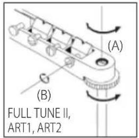
natural_image
Technical line drawing of a multi-layered mechanical component with mounting holes (no text or symbols)natural_image
Diagram of a screwdriver working on an electronic component with rotating arrows indicating rotation (no text or symbols present)アジャスタブルアーチトップブリッジ
natural_image
Technical line drawing of a mechanical component with labeled dimensions A and B (no text or symbols beyond labels)natural_image
Technical diagram of a mechanical assembly with rotating components (no text or symbols)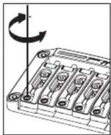
natural_image
Diagram of a battery pack with six slots and an arrow indicating rotation (no text or symbols)イントネーション調整
natural_image
Mechanical assembly diagram showing a rotating component with no visible text or symbols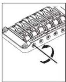
natural_image
Diagram of a mechanical component with multiple slots and a curved arrow indicating rotation (no text or symbols)弦交换
ご注意
natural_image
Mechanical assembly diagram showing a lever and two labeled components (J and K), no text or symbols present.弦交换
natural_image
Technical diagram of an internal combustion engine cylinder with no visible text or symbolsnatural_image
Technical line drawing of a mechanical assembly with no visible text or symbols弦交换
natural_image
Technical line drawing of an internal combustion engine block (no text or symbols)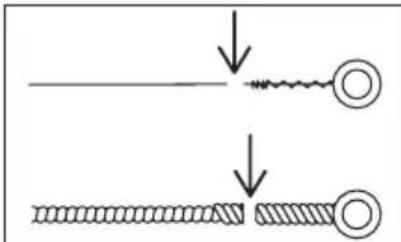
natural_image
Diagram showing two stages of a coiled wire or filament under compression, with no text or symbols present.ご注意
natural_image
Technical line drawing of a mechanical component with multiple cylindrical parts and a rotation arrow (no text or symbols)ロッキングトレモロ
EDGE トレモロブリッジ
Edge
Lo-Pro Edge
背面
natural_image
Technical line drawing of an electrical switchgear assembly (no text or symbols)natural_image
Technical line drawing of a mechanical component with no visible text or symbolsトレモロの取り付け角度調整
natural_image
Simple line drawing of a person sitting at a desk with a computer (no text or symbols)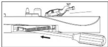
natural_image
Technical line drawing of a mechanical assembly with a tool and component, no visible text or symbols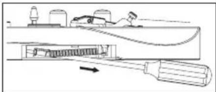
natural_image
Diagram of a mechanical device with a tool inserted into a housing, showing internal components and motion direction (no text or symbols)natural_image
Diagram of a mechanical assembly with a rotating component and base plates (no text or symbols)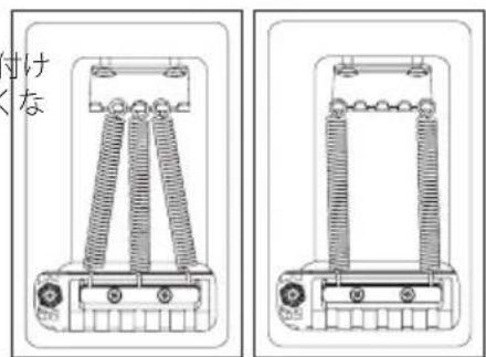
ご注意
natural_image
Technical line drawing of a mechanical assembly with gears and shafts (no text or symbols)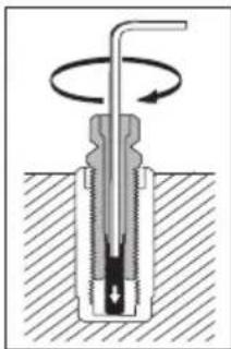
natural_image
Cross-sectional diagram of a mechanical component with rotational motion indicated by arrows (no text or labels)弦高調整
natural_image
Mechanical assembly diagram showing rotating components and fasteners (no text or labels)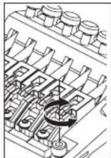
natural_image
Technical line drawing of a mechanical assembly with gears and housing (no text or symbols)弦交换
natural_image
Technical line drawing of a mechanical assembly with rotating components (no text or symbols)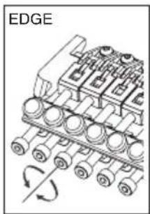
natural_image
Diagram of an engine block assembly with rotating wheels and a labeled edge (no text or symbols beyond label)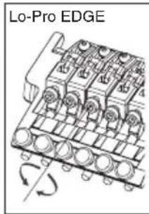
ご注意
natural_image
Mechanical assembly diagram showing a pipe inserted into a multi-chamber engine block (no text or symbols visible)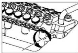
natural_image
Technical line drawing of an engine cylinder head assembly (no text or symbols)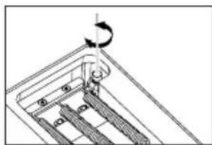
natural_image
Mechanical assembly diagram showing a rotating component with a curved arrow indicating rotation (no text or symbols)ご注意
natural_image
Line drawing of a mechanical component or tool (no text or symbols)natural_image
Diagram of a mechanical device with a tool and a person climbing it, showing internal components (no text or symbols)natural_image
Technical line drawing of a mechanical assembly with no visible text or symbolsnatural_image
Diagram of a mechanical assembly with a rotating component and a base plate (no text or symbols)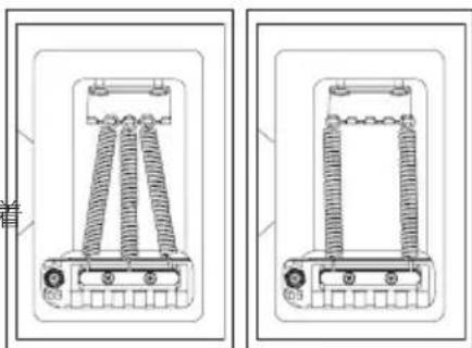
natural_image
Technical line drawing of two mechanical components with coiled springs (no text or symbols)ご注意
natural_image
Mechanical assembly diagram showing a rotating mechanism with no visible text or symbolsイントネーション調整
natural_image
Technical line drawing of a mechanical assembly with rotating components (no text or symbols)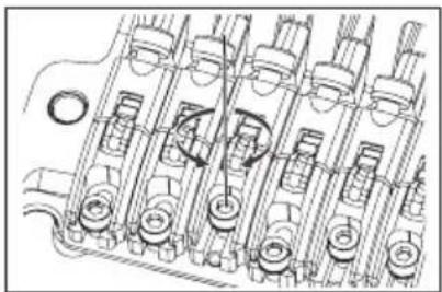
natural_image
Technical line drawing of a mechanical assembly with multiple cylindrical components and mounting holes (no text or symbols)natural_image
Technical line drawing of a mechanical assembly with multiple cylindrical components and rotational arrows (no text or symbols)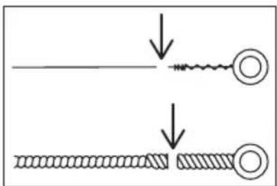
natural_image
Mechanical assembly diagram showing a rotating engine component with no visible text or symbols正面
背面2
トレモロアームの取り付け
natural_image
Mechanical assembly diagram showing a pipe inserted into a housing with internal components (no text or labels)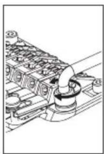
natural_image
Technical line drawing of a mechanical assembly with no visible text or symbolsnatural_image
Pure mechanical component diagram without any text, numbers, or symbols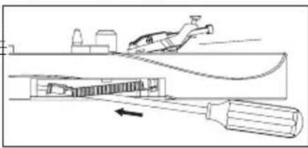
natural_image
Technical line drawing of a mechanical assembly with a tool and component, no visible text or symbols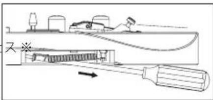
・ゼロ・ポイント・システム搭載モデル
natural_image
Technical line drawing of a mechanical assembly with spring and housing components (no text or symbols)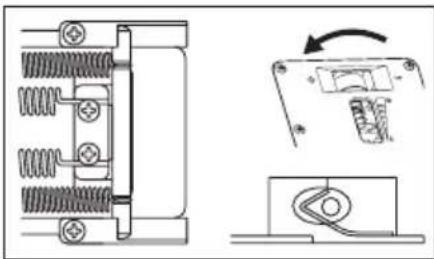
natural_image
Technical line drawing of a mechanical component with spring and housing, showing assembly and disassembly views (no text or symbols)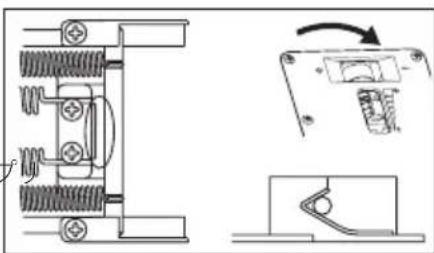
natural_image
Technical line drawing of a mechanical assembly with spring components and a close-up view of a switch (no text or symbols)natural_image
Technical line drawing of a mechanical component with an arrow indicating rotation (no text or symbols present)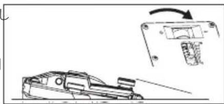
natural_image
Diagram showing a car on a road with an arrow indicating rotation or change, alongside a mechanical component (no text or symbols present)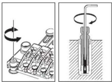
natural_image
Technical illustration of a mechanical assembly with rotating components and a cross-sectional view (no text or symbols)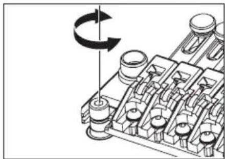
natural_image
Mechanical assembly diagram showing a rotating component with no visible text or symbolsご注意
natural_image
Technical line drawing of a mechanical assembly with no visible text or symbols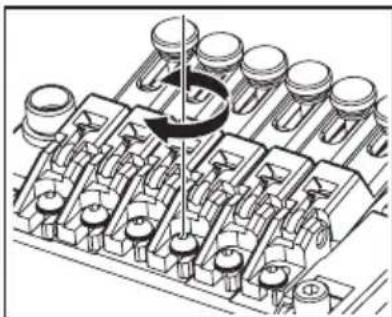
natural_image
Mechanical assembly diagram showing piston and crankshaft components (no text or labels)natural_image
Technical line drawing of a mechanical component with multiple circular cavities and a central ring (no text or symbols)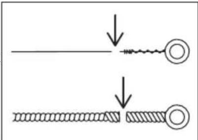
ご注意
natural_image
Technical line drawing of an internal combustion engine block (no text or symbols)正面
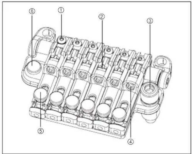
natural_image
Mechanical assembly diagram showing a valve inserted into a multi-chamber engine block (no text or labels)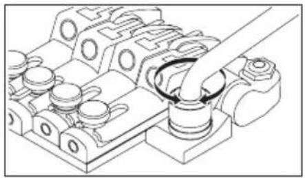
natural_image
Technical line drawing of a mechanical assembly with no visible text or symbolsnatural_image
Technical line drawing of a mechanical assembly with spring-loaded components and a close-up view of a circular component (no text or symbols)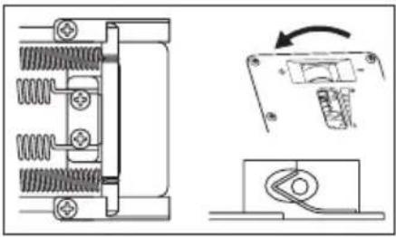
natural_image
Pure mechanical assembly diagram showing spring-loaded components and a close-up of a switch mechanism (no text or symbols)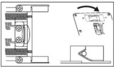
natural_image
Technical line drawing of a mechanical assembly with spring-loaded components and a close-up view of a switch mechanism (no text or symbols)natural_image
Mechanical assembly diagram showing internal components and spring-loaded parts (no text or labels)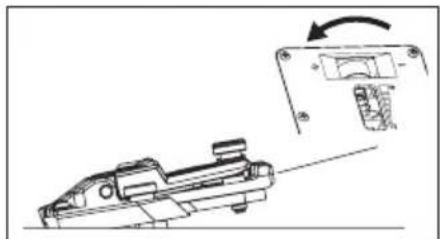
natural_image
Technical line drawing of a mechanical component with an arrow indicating rotation (no text or symbols present)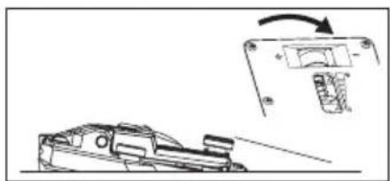
natural_image
Technical line drawing of a mechanical component with an inset showing a rotating lever mechanism (no text or symbols)natural_image
Mechanical assembly diagram showing a rotating shaft and housing components (no text or labels)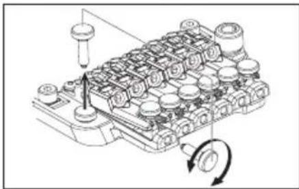
natural_image
Technical diagram of a mechanical assembly with no visible text or symbols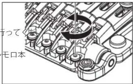
natural_image
Pure electrical circuit lines without any symbols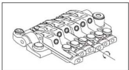
natural_image
Technical line drawing of a mechanical component with multiple cylindrical features and mounting holes (no text or symbols)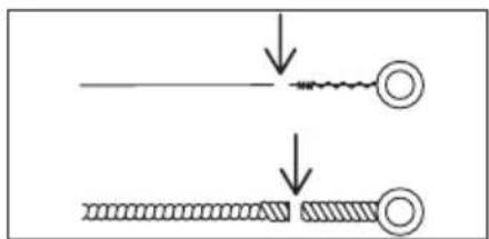
ファイン・チューニング
natural_image
Mechanical assembly diagram showing a rotating component with no visible text or symbols正面
natural_image
Simple line drawing of a mechanical component or tool (no text or symbols)natural_image
Technical line drawing of a mechanical assembly with a tool and component (no text or symbols)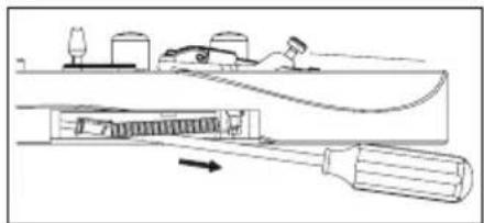
natural_image
Technical line drawing of a mechanical assembly with no visible text or symbolsnatural_image
Technical line drawing of an electrical insulator assembly (no text or symbols)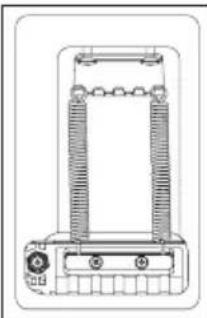
natural_image
Technical line drawing of a mechanical or electrical component with no visible text or symbolsご注意
natural_image
Mechanical assembly diagram showing rotating components on a conveyor belt (no text or labels)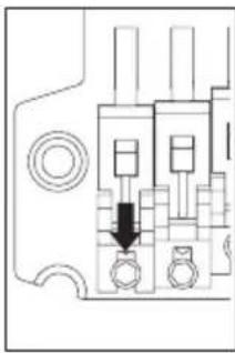
natural_image
Pure electrical circuit lines without any symbols弦交换
natural_image
Mechanical assembly diagram showing rotating components on a conveyor belt (no text or labels)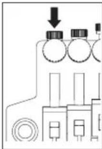
natural_image
Pure electrical circuit lines without any symbols
ご注意
natural_image
Mechanical assembly diagram showing a pipe inserted into a component (no text or symbols visible)
natural_image
Mechanical assembly diagram showing gear and shaft components with directional arrows (no text or labels)トレモロの取り付け角度調整
natural_image
Line drawing of a truck with no visible text, numbers, or symbols
natural_image
Diagram of a vehicle with a mechanical component and directional arrow indicating motion (no text or symbols)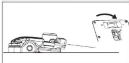
natural_image
Line drawing of a dump truck with an arrow indicating motion, next to a mechanical component (no text or symbols)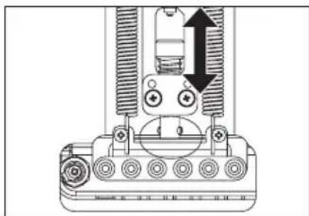
natural_image
Technical diagram of a mechanical assembly with gears and a central component, no visible text or symbols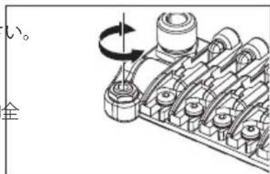
natural_image
Mechanical assembly diagram showing a row of gears and shafts with a rotating wheel (no text or labels)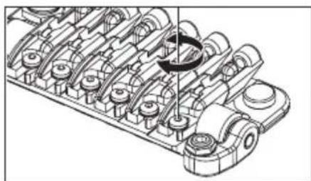
natural_image
Technical line drawing of a mechanical assembly with multiple cylindrical components and a central rotating component (no text or symbols)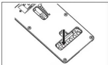
natural_image
Technical line drawing of a mechanical component with mounting holes and internal channels (no text or symbols)トレモロアームの取り付け
natural_image
Diagram of a mechanical device with a lever and curved arrow indicating motion (no text or symbols)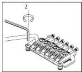
natural_image
Technical line drawing of a mechanical component with a curved pipe and numbered part (no text or symbols)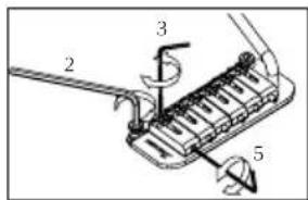
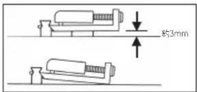
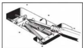
natural_image
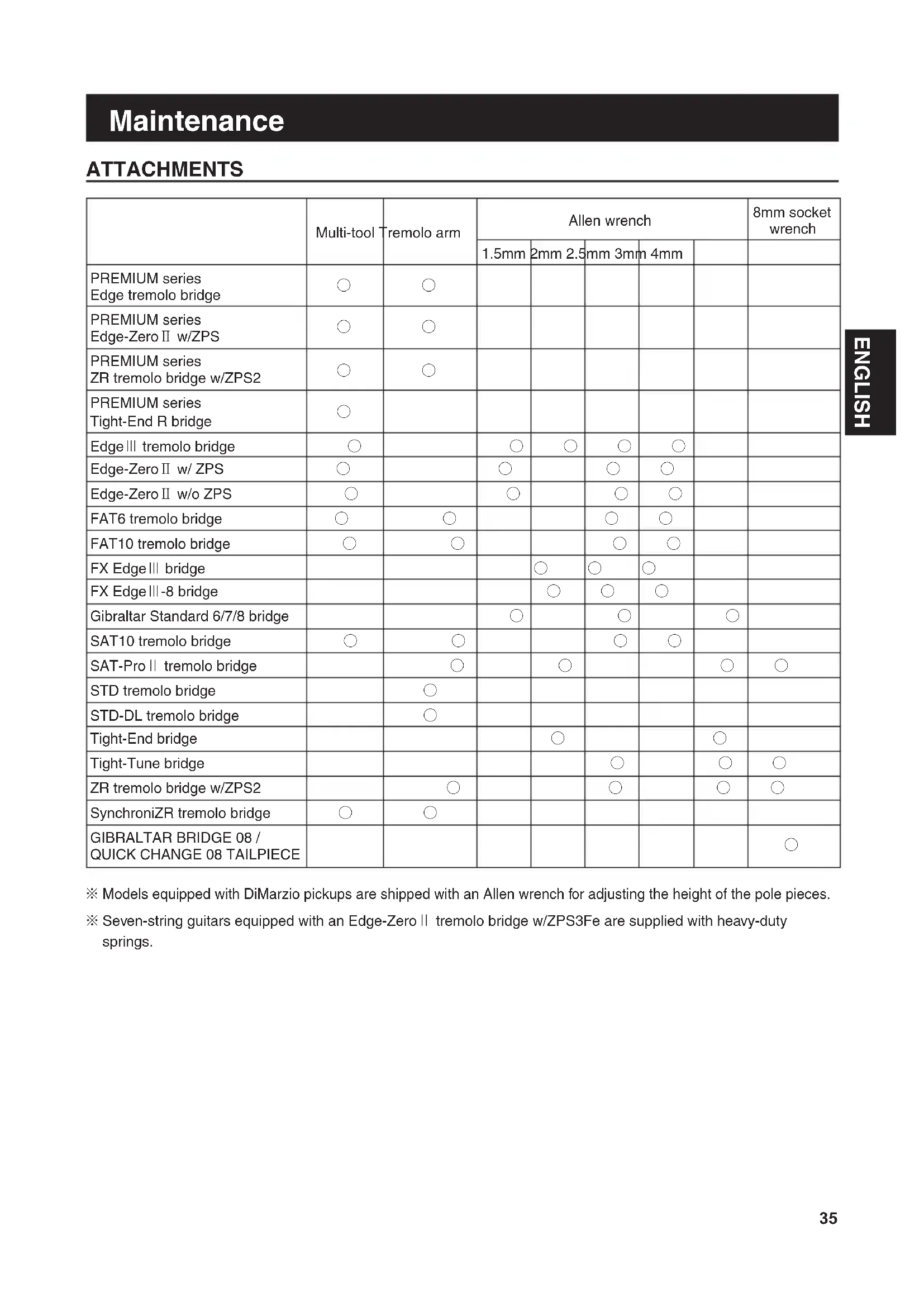
Technical illustration of a mechanical assembly with no visible text or symbols※ Models equipped with DiMarzio pickups are shipped with an Allen wrench for adjusting the height of the pole pieces.
※ Seven-string guitars equipped with an Edge-Zero II tremolo bridge w/ZPS3Fe are supplied with heavy-duty springs.
Electric Guitar Semi or Full Acoustic Guitar
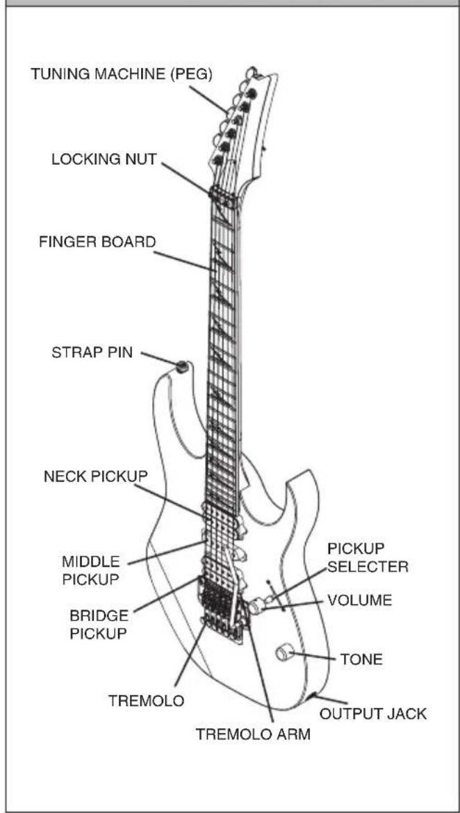
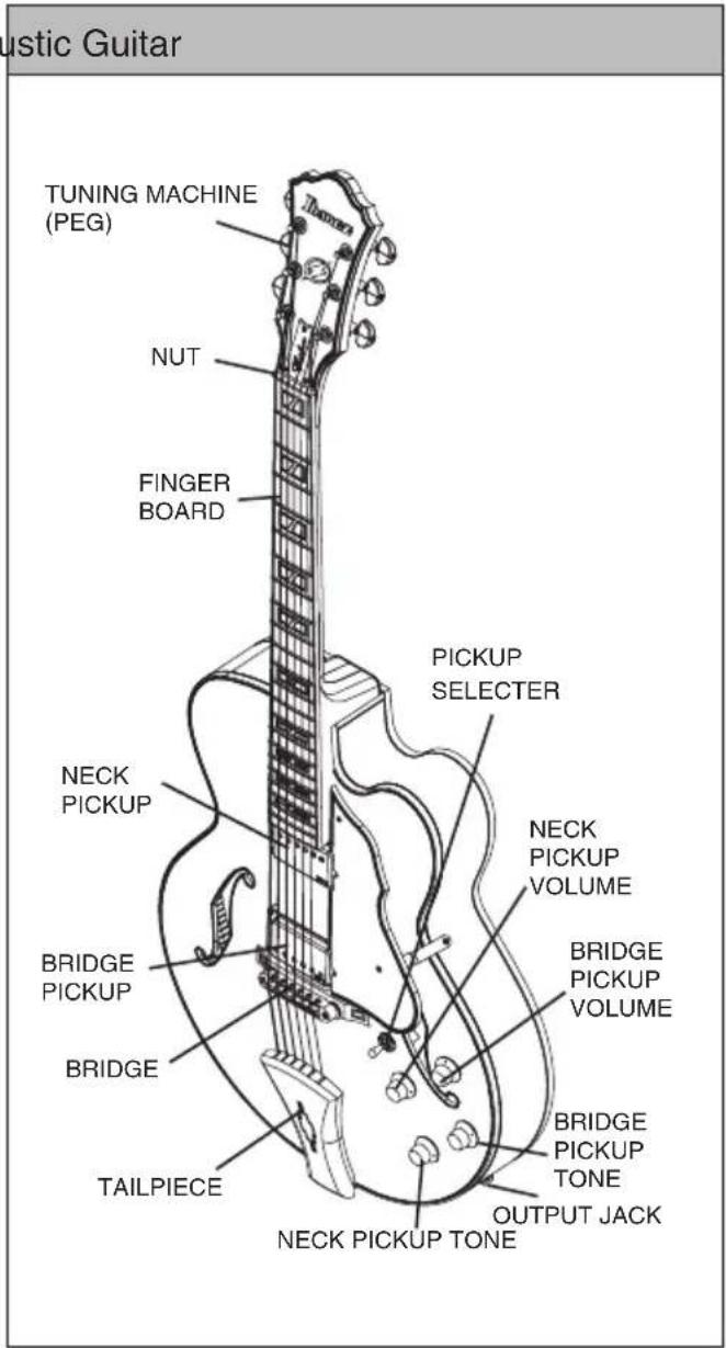
※ These illustrations show typical Ibanez models. The guitar you purchased might not match the illustration.
※ Tremolo/bridge adjustments will differ depending on the type of tremolo/bridge that is installed. For details, refer to the applicable tremolo/bridge section.
※ For details on the controls of each model, refer to the "Controls" section (p.228).
When shipped from the factory, Ibanez guitars are set up using the following tunings.
| 1st 2nd | 3rd 4th 5th | 6th 7th 8th | ||||||
| 6-strings E4 | B3 G3 D3 | A2 E2 - - | ||||||
| 7-strings E4 | B3 G3 D3 | A2 E2 B1 - | ||||||
| 8-strings D#4 | A#3 F#3 | C#3 G#2 D#2 | D#2 F1 |
Note that following models are set up differently.
Baritone guitar
| 1st | 2nd | 3rd | 4th | 5th | 6th | 7th | 8th |
| B | F# | D | A | E | B | - | - |
RGD、APEX
| 1st | 2nd | 3rd | 4th | 5th | 6th | 7th | |
| 6-strings | D4 | A3 | F3 | C3 | G2 | D2 | - |
| 7-strings | D4 | A3 | F3 | C3 | G2 | D2 | A1 |
MTM100
| 1st | 2nd | 3rd | 4th | 5th | 6th | 7th | 8th |
| C# | G# | E | B | F# | B | - | - |
TAM10
| 1st | 2nd | 3rd | 4th | 5th | 6th | 7th | 8th |
| E | B | G | D | A | E | B | E |
Use a tuner or tuning fork to tune up the sound of each open string to the above frequencies. If the pitch is higher than the above frequency, loosen the string to lower the pitch, and wind the string in small increments to tune it up. This is an easy way to stabilize your tuning. You may need to adjust the neck or the intonation if you tune your guitar to pitches other than those shown in these tables, or if you use strings of other than standard gauge.
For details on adjusting the neck or the intonation, refer to the sections "NECK ADJUSTMENT" (p. 38) or "INTONATION" (p. 38).
Memo
- Please note that extreme tuning or use of strings not intended for electric guitar may cause parts to break, and may cause unexpected injury.
STRING REPLACEMENT
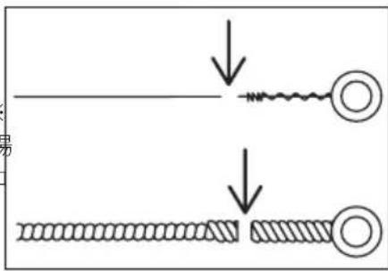
Strings will deteriorate over time, causing buzzing or inaccurate pitch. Replace the strings whenever your strings begin to rust or become discolored. We recommend that you replace all of the strings as a set at the same time. Bent, twisted, or damaged strings will not produce the appropriate quality sound and therefore should not be used.
natural_image
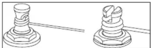
Technical line drawing of two mechanical components with threaded ends and flanges (no text or symbols)Wind the string around the tuning machine post two or three times from above, using about 5--7 cm of length and taking care that the string does not cross itself. The strings should be replaced one by one instead of removing all the strings at once. This is done to avoid stress on the neck and to reduce the risk of affecting tremolo balance.
※The method for removing and installing strings attached to a tremolo/bridge will differ depending on the type of tremolo/bridge. For details, refer to the section for the tremolo/bridge installed on your guitar.
Action refers to the distance between the frets and the string.
To measure the action, tune the guitar accurately; then place a ruler at the 14th fret and measure the distance from the top of the fret to the bottom of the string. In general, this distance should be 1.5--1.7 mm for the first string, and 2.0 mm--2.2 mm for the sixth string.
For a seven-string guitar, the seventh string should be at 2.2 mm--2.4 mm. For an eight-string guitar, the eighth string should be at 2.4 mm--2.6 mm.
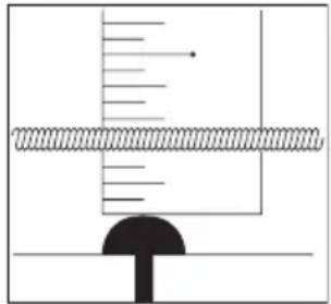
For strings other than those listed above, adjust the action so that the distance gradually increases from the first string toward the lowest string.
If the action is too high, the instrument will be difficult to play. If the action is too low, you may experience string buzz, muted notes, or poor sustain.
If you experience string buzz or muted notes even when the action is adjusted correctly, you might need to adjust the neck bow.
For details, refer to "Neck" (p. 38).
※ The method of adjusting the action will depend on the type of tremolo/bridge with which your guitar is equipped.
For details, refer to the appropriate tremolo/bridge section.
INTONATION
If you've changed string gauges or are using your guitar with an alternative tuning, you'll need to adjust the string length (intonation) to ensure that the correct pitch is sounded at all frets.
After tuning your guitar accurately, hold the guitar in playing position and compare the pitch of each string pressed down at the 12th fret with the pitch of the harmonic played at the 12th fret.
If the pitch of the fretted note at the 12th fret is
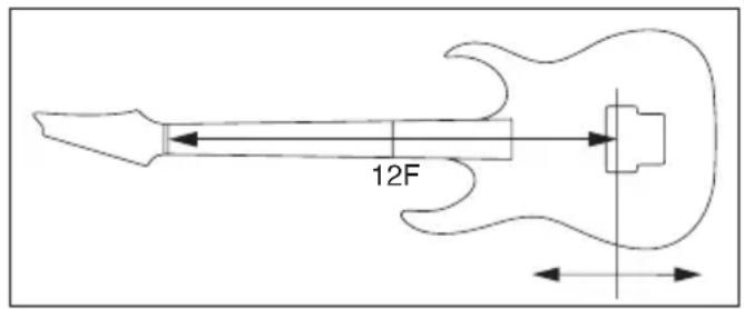
lower than the harmonic at that fret, move the saddle of the tremolo/bridge forward to shorten the string.
Conversely, if the pitch of the fretted note is higher than the pitch of the harmonic, move the saddle backward to lengthen the string.
Use a tuning meter to ensure accurate intonation adjustments. ※
※ The method of adjusting the saddle position will differ depending on the installed model of tremolo/bridge. For details, refer to the section for the tremolo/bridge that's installed on your guitar.
NECK ADJUSTMENT
The neck is constantly bearing the tension of the strings, and its curvature will be subtly affected not only by the state of tuning and the string gauge, but also by changes in temperature and humidity.
If you experience problems such as string buzz or muted notes even after the action and tuning are adjusted correctly, you should check and adjust the curvature of the neck.
① Check the curvature of the neck.
After tuning accurately, hold the guitar in playing position. Then press the fi rst string at the fi rst fret and also at the fret that is nearest to the point where the neck joins the body, and measure the gap between the string and fret at the eighth fret.
In the same way, measure this gap for the lowest string, and make adjustments so that the gaps are in the range of 0.3 mm--0.5 mm.
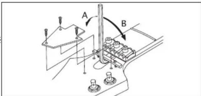
② If the gap is less than 0.3 mm, use the Allen wrench or socket wrench included with the guitar to turn the truss rod nut located at the headstock end of the neck in direction 'A', causing the neck curvature to be more convex.
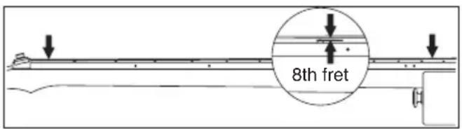
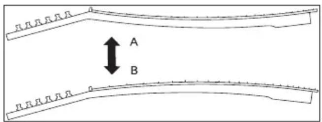
3 If the gap is greater than 0.5 mm, turn the Allen wrench or socket wrench in direction 'B', causing the neck curvature to be more concave.
Adjust the truss rod nut in small increments of a quarter ✉ turn, checking the tuning while you do so.
Memo
You must take care when adjusting the neck.
Forced adjustments can damage your guitar. If you are unable to adjust the neck correctly, please contact your Ibanez authorized dealer.
CLEANING
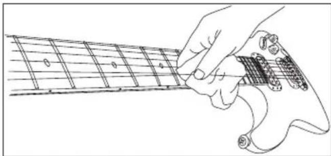
After playing, wipe sweat and oil off metal parts such as the underside of the strings, the frets, bridge saddles and nut. This will help to prevent rust.
Dirt or dust that adheres to metal parts may adversely affect their function. Wipe off stubborn dirt with a soft cloth moistened with a small amount of oil.
natural_image
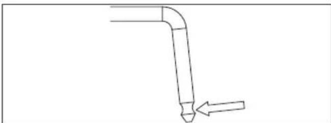
Line drawing of a hand playing guitar chord with fretboard and fretboard (no text or symbols)If the tremolo arm should squeak when turning, apply some grease to the notch on the shorter side of the tremolo arm.
To clean the fi nished surface, do not use volatile or abrasive cleaning compounds; instead gently wipe using a soft cloth with polish formulated specifi cally for musical instruments.
natural_image
Simple line drawing of a bent pipe with an arrow indicating direction (no text or symbols)To clean off dirt that has adhered to an oil fi nished body or neck, use a pencil eraser, fi ne sandpaper of #1000 or fi ner grade, or #0000 steel wool. You can prevent drying by polishing once or twice a year with a colorless furniture fi nish oil or gun oil applied to #0000 steel wool or a cloth. Unfi nished fi ngerboards should be carefully wiped with a cloth moistened with a small amount of fi ngerboard oil or high-quality lemon oil, wiping carefully to the edge of the frets.
BATTERY
If your guitar has a built-in pre-amplifi er or equalizer, it will be powered by a battery. Replace the battery when you notice that the volume level has decreased or the sound has become distorted.
Some models use a 006P (9V) battery, and other models use two AA (1.5V) batteries.
Check the type of batteries used by your guitar, and replace them with the same type of batteries.
The batteries are found in the battery box located on the back of the body.
On models equipped with a battery, the output jack also functions as a power switch; inserting a plug into the jack will turn on the power.
Memo
- To prevent the battery from running down, remove the plug from the output jack if you will not be using it for an extended period.
Guitar Bridges
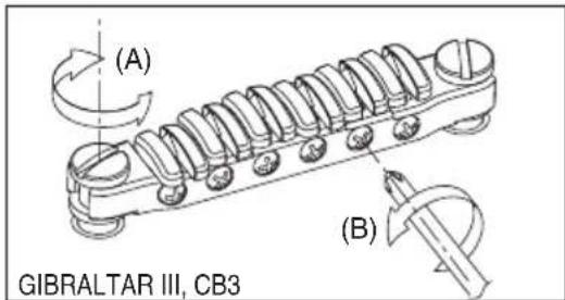
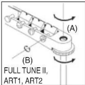
GIBRALTAR III (GUITAR & BASS), CB3, & FULL TUNE III, ART1, ART2
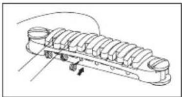
The action can be adjusted by using a slot head (-) screwdriver to turn the adjustment bolt at either end (A).
Intonation can be adjusted by moving the saddle forward or backward by turning the intonation adjustment screw (B) at the rear of the bridge. You can use either a Phillips (+), a fl at head (-) screwdriver, or the optional hex wrench.
natural_image
Technical line drawing of a mechanical component with multiple cylindrical parts and mounting holes (no text or symbols)REPLACING THE STRINGS : CB3
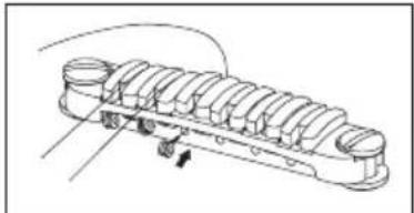
Install strings by inserting them from the front of the bridge.
Before adjusting the action on the Gibraltar III bridge, loosen the strings suf-※fi ciently so that you will not need to turn the screws with excessive force, which could damage the screw holes.
HARDTAIL BRIDGE
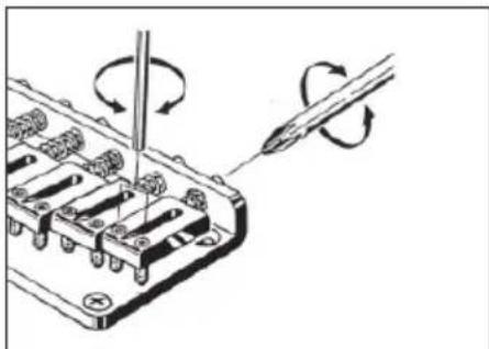
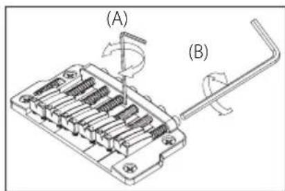
To change strings, thread the new strings through the string grommets located on the back of the guitar and bring them up and over the saddle. The intonation can be adjusted by adjusting the saddle forward or backward using a Phillips (+) head screwdriver on the intonation adjustment screw at the rear of the bridge. String height is controlled by raising or lowering the small Allen screws using a wrench on either side of the saddle.
The adjustment method is the same for 7-string and 8-string models. ※
natural_image
Diagram of a screwdriver working on an electronic component with rotating arrows indicating rotation (no text or symbols present)GIBRALTER STANDARD BRIDGE (7-STRING / 8-STRING MODELS)
To install a new string, pass it through the string stopper ferrule from the back of the guitar body.
To adjust the height of the strings, use a 1.5mm hexagonal wrench to turn and adjust the height of each saddle (A).
To adjust the intonation, use a 2.5mm hexagonal wrench to turn the intonation adjustment screws of each saddle on the back of the bridge (B).
The adjustment method is the same for 7-string and 8-string models. ※
GIBRALTAR BRIDGE 08 / QUICK CHANGE 08 TAILPIECE
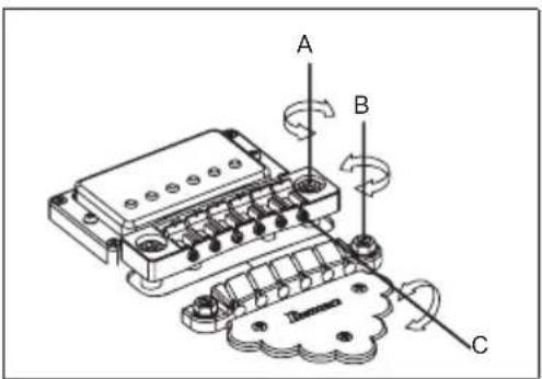
To adjust the string height, turn the stud bolts located at the left and right ends of the bridge (A) using a slotted (-) screw driver. Before adjustment, loosen the lock nut using an 8mm nut driver. After adjustment, tighten the lock nut again to fix the bridge.
To adjust the tailpiece height, turn the adjustment screws (B) on both sides with a slotted (-) screw driver. Before adjustment, loosen the lock nut. After adjustment, fix it again in the same way as the bridge. If the lock nut of the bridge and tailpiece is loose, it may cause distortion or resonance. Raising the tailpiece will reduce the string tension, which will provide a softer feel and make it easier to bend the strings.
To adjust the intonation of each saddle, turn the intonation adjustment screw using a slotted (-) screw driver (C).
ADJUSTABLE ARCH TOP BRIDGE
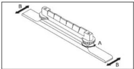
To adjust the string height, adjust the height of the entire bridge by using your fingers to turn the thumb wheel screws (A) located at either side of the bridge. (It is not possible to individually adjust the height of each string.)
To adjust the intonation, loosen the strings and move the entire bridge forward or backward; then tune the guitar and check the intonation. Repeat this adjustment until the intonation is correct. Take care that the bridge does not fall over.
When replacing the strings, it is recommended that they be replaced one by one so that the bridge does not become displaced.
natural_image
Technical line drawing of a mechanical component with labeled dimensions A and B (no text or symbols beyond labels)Vintage Vibrato
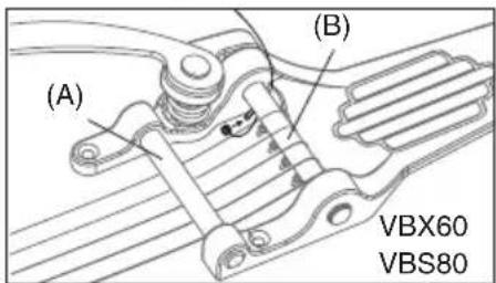
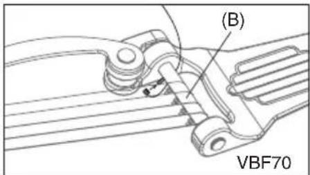
Replace the strings one by one. Fix the ball end onto the post of the bar (B), extend the string over the bar, and then
wrap it around the peg. For a model with a retainer bar (A), VBX60/VBX80, pass the string over the bar and then beneath the retainer bar before wrapping it around the peg. While replacing strings, always pull the string lightly toward the headstock and exercise care not to allow the ball-end to go off the post. Check that the string is correctly placed on the saddle while tuning. After completing tuning, proceed to replacement of the next string. After finishing replacing all strings, carry out tuning again for the entire unit.
Memo
Removing all strings at the same time may have a serious impact on the state of each section of the guitar due to sudden changes of tension imposed on the guitar. Be sure to replace the strings one by one.
Tailpieces
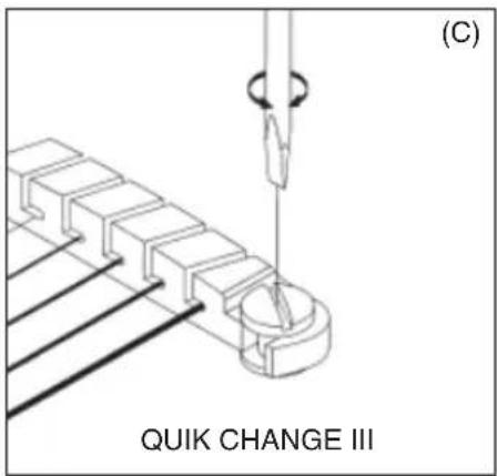
QUIK CHANGE TAILPIECES
To adjust the height of the tailpiece, turn the stud bolt on the right and left ends of the tailpiece with a slot head screwdriver or a coin.
To install a new string, pass it through the slot of the tailpiece and hook the ball end into the back of the tailpiece.
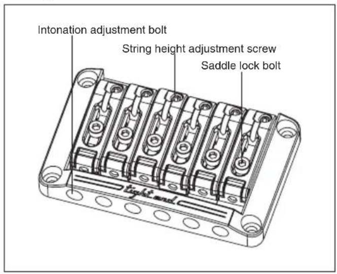
Tight-End bridge / Tight-End R bridge (for 6-string and 7-string)
Tight-End
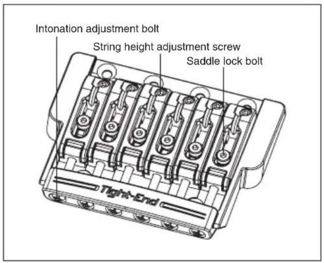
Tight-End
ADJUSTING THE ACTION
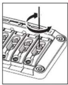
① Use an Allen wrench (2 mm) to loosen the saddle lock bolts.
② To adjust the saddle height, use the Allen wrench (2 mm) to turn the saddle height adjustment screws.
※ When you've finished making adjustments, tighten the saddle lock bolts.
natural_image
Technical diagram of a mechanical component with a rotating arrow indicating rotation (no text or symbols present)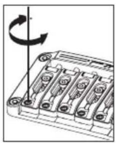
natural_image
Diagram of a battery pack with rotating arrow indicating rotation (no text or symbols)ADJUSTING THE INTONATION
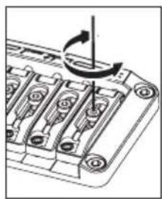
① Use an Allen wrench (2 mm) to loosen the saddle lock bolts.
② Use a Phillips screwdriver to adjust the saddle position by turning the intonation adjustment bolt.
③ Use an Allen wrench (2 mm) to tighten the saddle lock bolts, and use a Phillips screwdriver to lightly tighten the intonation adjustment screw in the clockwise direction. (Tighten lightly, so as not to affect the saddle position.)
natural_image
Technical diagram of a mechanical component with rotating shaft and housing (no text or symbols)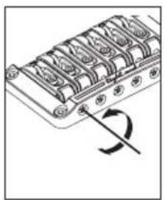
natural_image
Diagram of a mechanical component with multiple slots and a curved arrow indicating rotation (no text or symbols)Make sure that the guitar is tuned correctly before you check the intonation. ※
STRING REPLACEMENT
To install a new string, pass it through the string stopper ferrule from the back of the guitar body.
TIGHT-TUNE BRIDGE
The Tight-Tune bridge achieves the optimum level of stability and sound transference while suppressing unnecessary vibrations by allowing each movable part of the bridge to be locked. The bridge has a stud lock function for fi xing the bridge more securely onto the body. Furthermore, the tailpiece is equipped with a ball-end lock function to retain the ball end so that it will not come off.
ADJUSTING THE ACTION
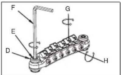
Loosen the locking nuts (D) on the right and left sides of the bridge unit, and adjust the height of the bridge unit by turning the stud lock screws (E) with a 3 mm Allen wrench. Note that it is not possible to adjust the height of individual strings. After completing the adjustment, tighten the locking nuts.
STUD LOCK FUNCTION
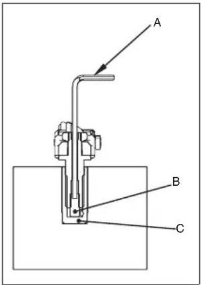
After adjusting the action, turn the stud lock bolt (B) clockwise inside the stud bolt with a 2 mm Allen wrench. Keep tightening until the stud lock bolt contacts the anchor bolt (C) and the bolt cannot be turned any further.
Memo
When adjusting the action, be sure to fully loosen the stud lock bolt (B) beforehand by turning it counterclockwise with a 2 mm Allen wrench. Otherwise, damage may occur.
ADJUSTING THE INTONATION
Loosen the saddle lock screws (G) with a Phillips screwdriver, and turn the intonation adjustment screw (H) with a Phillips screwdriver to adjust the saddle position. Tune the guitar and check the intonation. Repeat these adjustments until the required intonation is reached, and then tighten the saddle lock screws.
Memo
A loose intonation adjustment screw (H) may cause resonance. If this occurs, gently tighten the intonation adjustment screw, exercising care not to allow the saddle to move.
REPLACING THE STRINGS
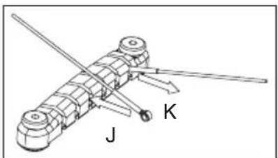
Insert the ball-end of the string into the slot of the tailpiece in the direction shown by arrow (J). The ball-end lock function retains the ball-end. To remove the string, pull it toward direction (K).
natural_image
Technical line drawing of a mechanical assembly with labeled components J and K (no text or symbols beyond labels)Locking Bridge
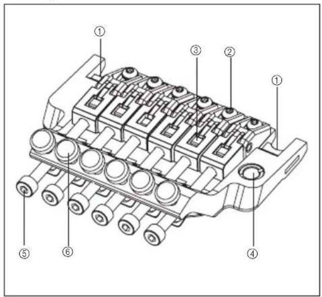
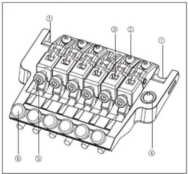
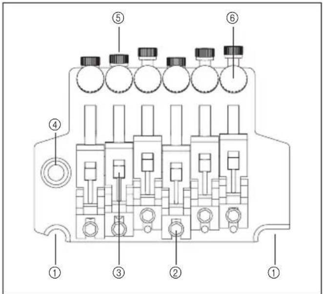
FX EDGE III/FX EDGE III-8 BRIDGE
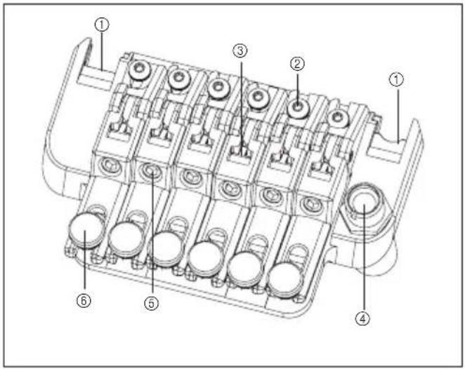
FX Edge III
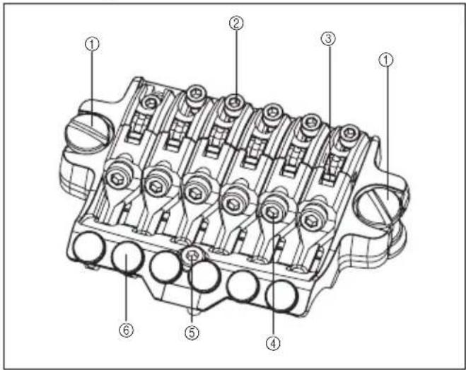
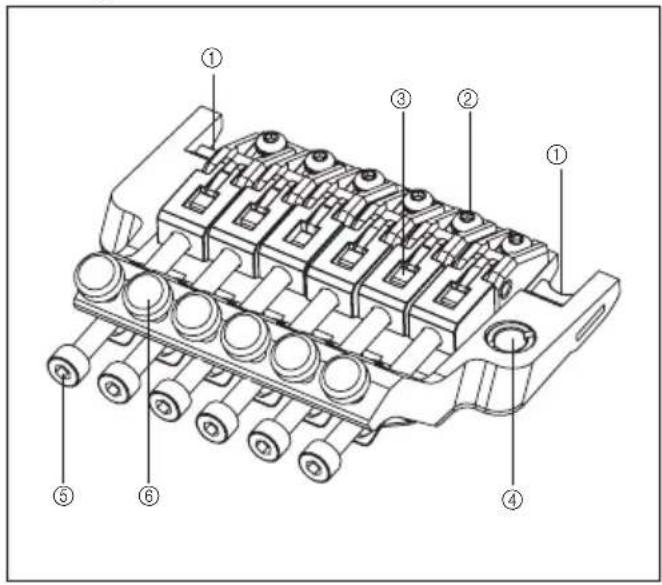
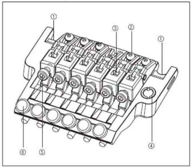
① Main stud
② Saddle lock bolt
③ String holder block
④ String stopper bolt
⑤ Rear stud
⑥ Fine tuning bolt
ADJUSTING THE ACTION
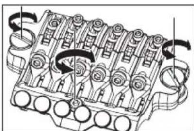
① To adjust the string height, use a slotted screwdriver to turn the main studs at the left and right of the bridge unit to adjust the height of the entire tremolo unit. (It is not possible to adjust the height of individual strings.)
② Use an Allen wrench (3 mm) to turn the rear studs, adjusting them so that the bridge is approximately parallel with the surface of the guitar body.
natural_image
Technical diagram of an internal combustion engine cylinder with no visible text or labelsAs the action will change when you adjust the rear studs, it is recommended ※ that you check the final action after you've adjusted the rear studs.
To prevent the screw holes from being damaged, loosen the strings sufficiently before you adjust the main studs so that you will not have to use excessive force when turning the studs.
ADJUSTING THE INTONATION
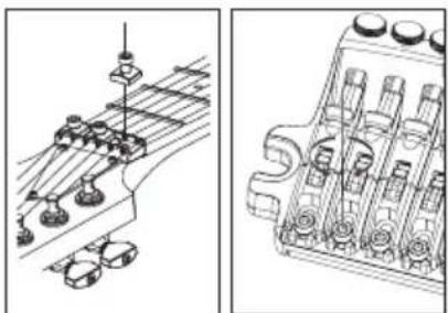
① Use an Allen wrench (3 mm) to loosen the pressure pad bolts of the locking nut, and loosen the strings sufficiently.
② Use an Allen wrench (2 mm) to loosen the saddle lock bolt, and adjust the saddle position.
Before checking the intonation, fi rmly tighten the saddle lock bolts and tune ※ the guitar correctly. When you've fi nished making adjustments, tighten the saddle lock bolts and the pressure pad bolts of the locking nut.
natural_image
Technical line drawing of mechanical components and housing assembly (no text or symbols)REPLACING THE STRINGS
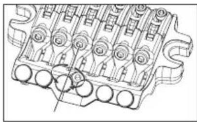
① Use an Allen wrench (3 mm) to loosen the pressure pad bolts of the locking nut, and remove the string from the tuning peg.
② Use an Allen wrench (3 mm) to loosen the string stopper bolt of the bridge unit, then pull the string out of the saddle and remove it.
③ Use wire cutters to cut off the ball end of the new string.
④ Insert the tip of the string from which you cut off the ball end between the saddle and the string holder block, and tighten the string stopper bolt to fasten the string.
⑤ Wind the string onto the tuning peg, and tune it.
⑥ When you've fi nished tuning, tighten the pressure pad bolts of the locking nut
natural_image
Technical line drawing of a mechanical component with multiple cylindrical features and mounting holes (no text or symbols)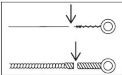
Memo
- Before you tune, make sure that the string stopper bolts are firmly tightened.
FINE TUNING
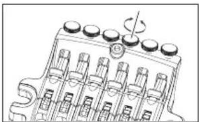
Even after you've used the locking nuts to lock the strings, you can use the fi ne tuners to fi ne-tune each string.
The range of adjustment after the strings are locked will be widest if you leave all fi ne-tuning bolts near the center of their adjustable range before you tune.
natural_image
Technical line drawing of a mechanical component with multiple cylindrical parts and a central knob (no text or symbols)Locking Tremolos
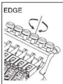
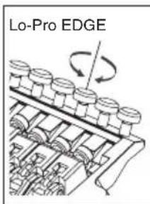
EDGE TREMOLO BRIDGE
Edge
Lo-Pro Edge
Rear
① Knife edge
② Saddle lock bolt
③ String holder block
④ Tremolo arm socket
⑤ String stopper bolt
⑥ Fine tuning bolt
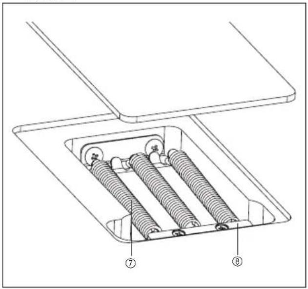
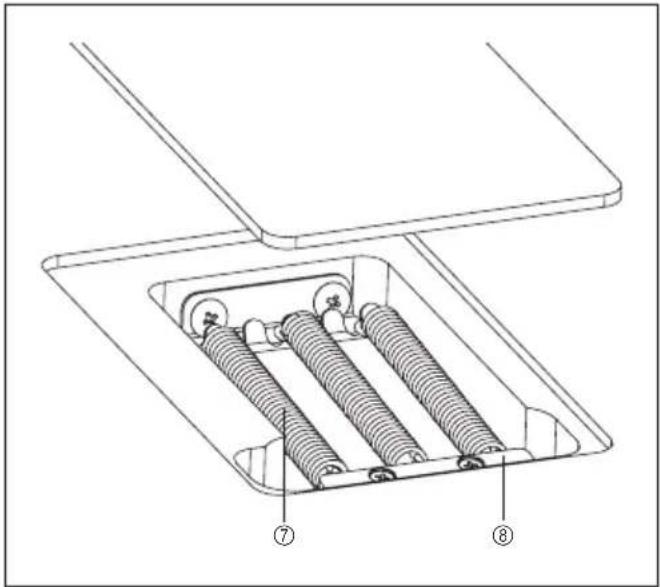
⑦ Tremolo spring
⑧ Spring lock
ATTACHING THE TREMOLO ARM
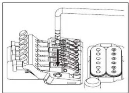
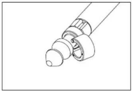
① The tremolo arm employs a snap-in/snap-out design. Hold the corner of the tremolo arm, and press it firmly into the arm socket of the base plate.
natural_image
Technical line drawing of a mechanical or electrical component assembly (no text or symbols visible)② The tightness of the tremolo arm attachment can be adjusted by adding or removing Tefl on washers. Using a larger number of washers will make the attachment tighter, and removing all the washers will leave the arm free. The Tefl on washers can be added or removed diagonally via the slit.
Memo
If the arm is no longer held firmly in place even after you've added Tefl on washers, replace the old Tefl on washers with new ones.
ADJUSTING THE TREMOLO ATTACHMENT ANGLE
The tremolo attachment angle is adjusted by changing the balance between the string tension and the tension of the tremolo springs installed on the back of the guitar body. You'll obtain the optimal performance by adjusting this so that the tremolo is approximately horizontal to the surface of the guitar body.
① With the guitar tuned correctly, check the angle of the tremolo.
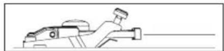
② If the tremolo is tilted toward the front, insert a Philips screwdriver through the slit in the tremolo spring cover on the back of the body, and tighten the screw to increase the tension of the tremolo springs.
③ If the tremolo is tilted toward the rear, loosen the screw to decrease the tension of the tremolo springs.
The tremolo angle adjustment will affect the tuning, because the balance of tension between the strings and the springs will change each time you adjust the tension of the tremolo springs. You'll need to tune repeatedly while making this adjustment.
natural_image
Technical line drawing of a mechanical component with threaded ends and a cylindrical shaft (no text or symbols)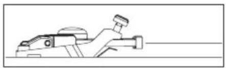
natural_image
Line drawing of a mechanical component or tool with no visible text or symbols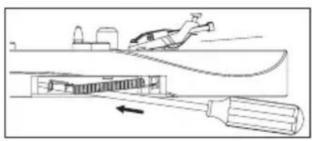
natural_image
Diagram of a mechanical device with a tool inserted, showing internal components and motion direction (no text or symbols)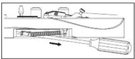
TREMOLO SPRINGS
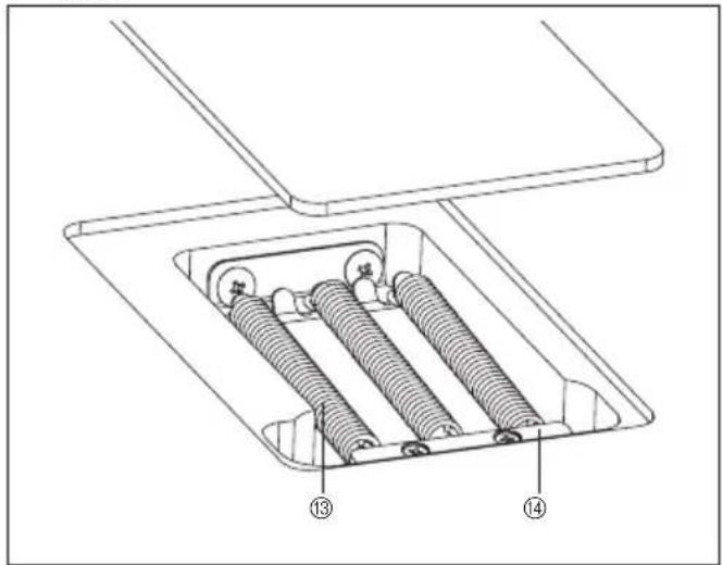
When the guitar is shipped from the factory, it is set up with three tremolo springs installed in parallel. If the balance of tension between the strings and the tremolo springs has changed significantly, such as when you've switched string gauges or are using a dropped tuning, you may need to change the number of tremolo springs or change the way in which they are installed.
① Use a Philips screwdriver to remove the spring lock.
② If you want to increase the tension, install the outer two tremolo springs diagonally.
③ If you want to decrease the tension, remove the center tremolo spring.
If you want to install four or more tremolo springs, attach them using the screw holes that were being used to attach the spring lock. (It will no longer be possible to attach the spring lock.)
natural_image
Diagram of a mechanical assembly with a rotating component and a base plate (no text or symbols)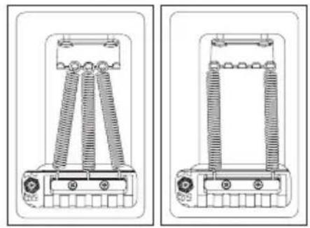
natural_image
Technical line drawing of two mechanical components with coiled springs and mounting brackets (no text or symbols)Memo
Loosen the strings sufficiently before you install or remove tremolo springs. Be aware that if you remove all of the springs, the tremolo unit will detach from the guitar.
To reattach the tremolo, insert the knife edge of the tremolo securely into the groove of the stud bolts, and then install the tremolo springs.
STUD LOCK
The Edge/Lo-Pro Edge tremolo bridge uses a stud lock mechanism.
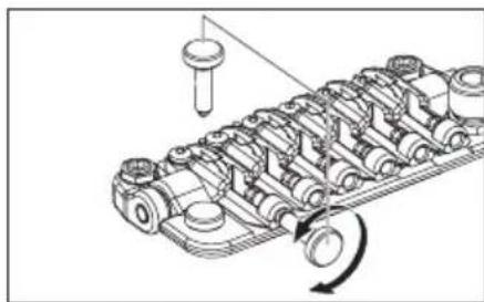
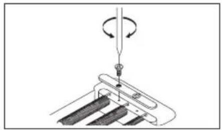
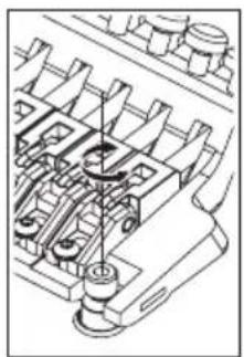
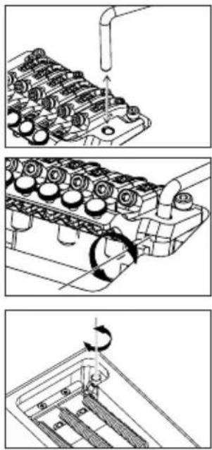
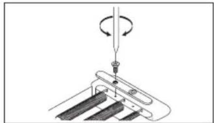
① Insert an Allen wrench (1.5 mm) through the hole in the top of the stud bolt.
② Turn the stud lock bolt clockwise, tightening it until it contacts the anchor nut and can no longer rotate.
The stud lock will be released when you loosen the stud lock bolt. ※
ADJUSTING THE ACTION
To adjust the height of the entire tremolo unit, use an Allen wrench (4mm) to turn the stud bolts located at the left and right of the tremolo unit. (It is not possible to make adjustments for each string individually.)
natural_image
Technical line drawing of a mechanical assembly with gears and shafts (no text or symbols)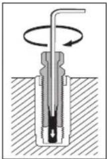
natural_image
Cross-sectional diagram of a mechanical device with rotating shaft and base, no text or symbols present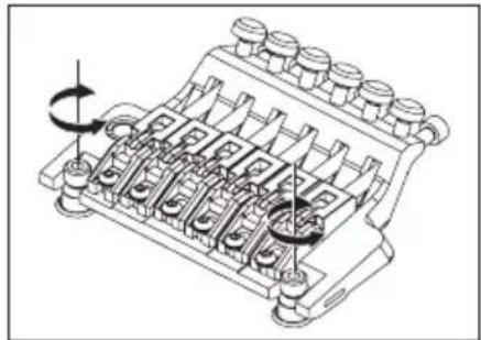
natural_image
Technical line drawing of a mechanical component with multiple ports and rotating arms (no text or symbols)Memo
Make sure that the stud lock is released before you adjust the action.
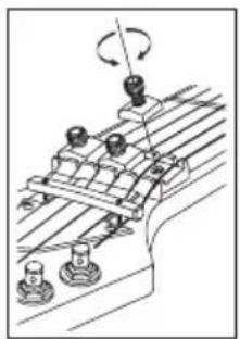
ADJUSTING THE INTONATION
① Use an Allen wrench (3 mm) to loosen the pressure pad bolts of the locking nut, and loosen the strings sufficiently.
② Use an Allen wrench (2 mm) to loosen the saddle lock bolts, and adjust the saddle position.
Before checking the intonation, firmly tighten the saddle lock bolts and × tune the guitar correctly. When you've finished making adjustments, tighten the saddle lock bolts and the pressure pad bolts of the locking nut.
natural_image
Technical line drawing of a mechanical assembly with rotating components (no text or symbols)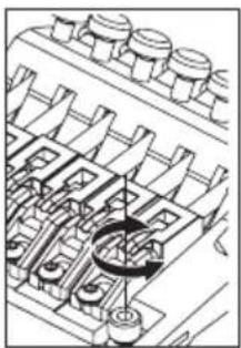
natural_image
Technical diagram of a mechanical assembly with no visible text or symbolsREPLACING THE STRINGS
① Use an Allen wrench (3 mm) to loosen the pressure pad bolts of the locking nut, and remove the string from the tuning peg.
② Use an Allen wrench (3 mm) to loosen the string stopper bolt of the tremolo unit; then pull the string out of the saddle and remove it.
③ Use wire cutters to cut off the ball end of the new string.
④ Insert the tip of the string from which you cut off the ball end between the saddle and the string holder block, and tighten the string stopper bolt to fasten the string.
⑤ Wind the string onto the tuning peg, and tune it.
⑥ When you've fi nished tuning, tighten the pressure pad bolts of the locking nut.
Removing all strings at the same time will cause the tremolo attachment ※ angle to change signifi cantly, so we recommend that you replace the strings one at a time. If you remove all strings at the same time, tuning will be easier if you wedge a piece of cloth below the tremolo to secure it so that the tremolo attachment angle won't change signifi cantly.
natural_image
Technical line drawing of a mechanical assembly with rotating components (no text or symbols)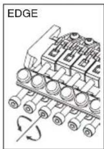
natural_image
Diagram of an engine block assembly with rotating components and a labeled edge (no text or symbols beyond label)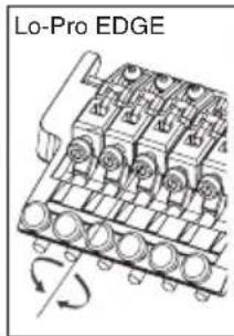
Memo
Before you tune, make sure that the string stopper bolts are firmly tightened.
FINE TUNING
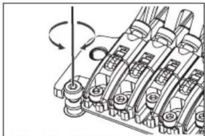
Even after you've used the locking nuts to lock the strings, you can use the fi ne tuners to fi ne-tune each string.
The range of adjustment after the strings are locked will be widest if you leave all fine-tuning bolts near the center of their adjustable range before you tune.
Overview
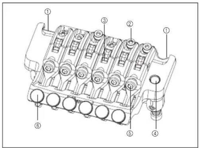
① knife edge
② saddle lock bolt
③ string holder block
④ tremolo arm socket
Rear
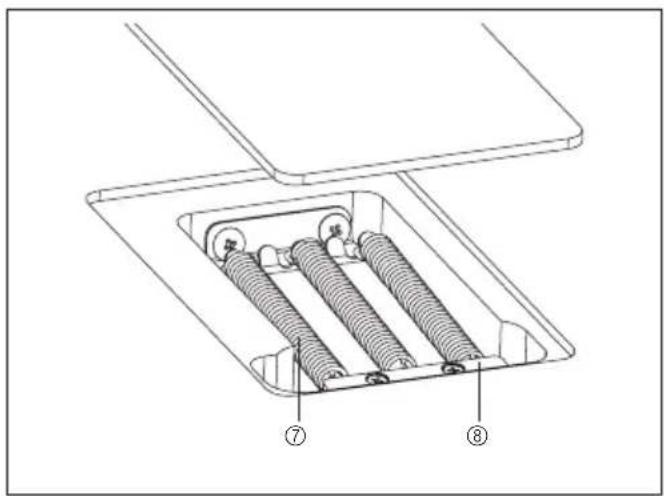
⑤ string stopper bolt
⑥ fi ne tuning bolt
⑦ tremolo spring
⑧ spring lock
ATTACHING THE TREMOLO ARM
① The tremolo arm employs a snap-in/snap-out design. Hold the corner of the tremolo arm, and press it firmly into the arm socket of the base plate.
※ The tremolo arm of the EDGE III Herman Li Ver. installed on the EGEN8 is a screw-in type.
After inserting the tremolo arm into the arm socket, rotate it to fasten it in place.
② To adjust the tightness of the tremolo arm, use an Allen wrench (2 mm) to adjust the torque adjustment screw via the adjustment hole on the side of the tremolo block. Tightening the torque adjustment screw clockwise will make the tremolo arm tighter; loosing the screw will make the arm looser.
③ To adjust the height of the tremolo arm, remove the tremolo spring cover on the back of the guitar and use an Allen wrench (3 mm) to turn the height adjustment screws located on the bottom of the tremolo block. Tightening the screws clockwise will increase the height.
Memo
In addition to the one described above, the tremolo arm also has a torque adjustment screw located at the bottom of the tremolo block.
The torque adjustment screw at the bottom of the tremolo block is already adjusted when the guitar is shipped from the factory; if it should require adjustment, remove the tremolo unit from the guitar and then adjust the screw.
Before attaching the tremolo arm, make sure that the torque adjustment screw has not come loose or fallen out.
ADJUSTING THE TREMOLO ATTACHMENT ANGLE
The tremolo attachment angle is adjusted by changing the balance between the string tension and the tension of the tremolo springs installed on the back of the guitar body. You'll obtain the optimal performance by adjusting this so that the tremolo is approximately horizontal to the surface of the guitar body.
① With the guitar tuned correctly, check the angle of the tremolo.
② If the tremolo is tilted toward the front, insert a Philips screwdriver through the slit in the tremolo spring cover on the back of the body, and tighten the screw to increase the tension of the tremolo springs.
③ If the tremolo is tilted toward the rear, loosen the screw to decrease the tension of the tremolo springs.
natural_image
Simple line drawing of a mechanical component or tool (no text or symbols)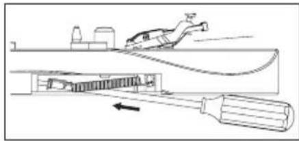
natural_image
Technical line drawing of a mechanical assembly with a tool and component, no visible text or symbols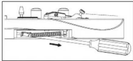
natural_image
Technical line drawing of a mechanical device with no visible text or symbols※ The tremolo angle adjustment will affect the tuning, because the balance of tension between the strings and the springs will change each time you adjust the tension of the tremolo springs. You'll need to tune repeatedly while making this adjustment.
TREMOLO SPRINGS
When the guitar is shipped from the factory, it is set up with three tremolo springs installed in parallel. If the balance of tension between the strings and the tremolo springs has changed signifi cantly, such as when you've switched string gauges or are using a dropped tuning, you may need to change the number of tremolo springs or change the way in which they are installed.
① Use a Philips screwdriver to remove the spring lock.
② If you want to increase the tension, install the outer two tremolo springs diagonally.
③ If you want to decrease the tension, remove the center tremolo spring.
If you want to install four or more tremolo springs, attach them using the screw holes that were being used to attach the spring lock. (It will no longer be possible to attach the spring lock.)
natural_image
Diagram of a mechanical assembly with a rotating component and base plates (no text or symbols)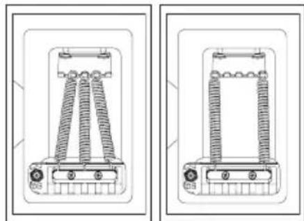
natural_image
Technical line drawings of two mechanical components with coiled springs (no text or symbols)Memo
Loosen the strings sufficiently before you install or remove tremolo springs.
Be aware that if you remove all of the springs, the tremolo unit will detach from the guitar.
To reattach the tremolo, insert the knife edge of the tremolo securely into the groove of the stud bolts, and then install the tremolo springs.
ADJUSTING THE ACTION
To adjust the height of the entire tremolo unit, use an Allen wrench (3 mm) to turn the stud bolts located at the left and right of the tremolo unit. (It is not possible to make adjustments for each string individually.)
natural_image
Mechanical assembly diagram showing gear and shaft components with rotational motion arrows (no text or labels)ADJUSTING THE INTONATION
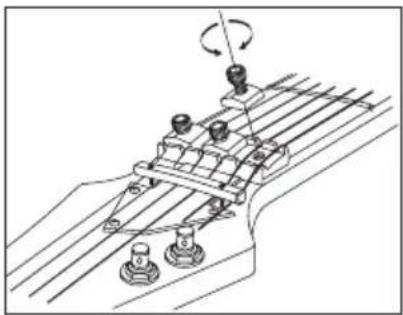
① Use an Allen wrench (3 mm) to loosen the pressure pad bolts of the locking nut, and loosen the strings sufficiently.
② Use an Allen wrench (2 mm) to loosen the saddle lock bolts, and adjust the saddle position.
natural_image
Technical line drawing of a mechanical assembly with rotating components (no text or symbols)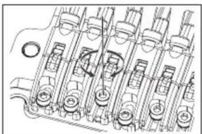
natural_image
Technical line drawing of an engine cylinder assembly (no text or labels)※ Before checking the intonation, firmly tighten the saddle lock bolts and tune the guitar correctly. When you've finished making adjustments, tighten the saddle lock bolts and the pressure pad bolts of the locking nut.
REPLACING THE STRINGS
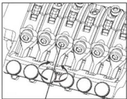
① Use an Allen wrench (3 mm) to loosen the pressure pad bolts of the locking nut, and remove the string from the tuning peg.
② Use an Allen wrench (3 mm) to loosen the string stopper bolt of the tremolo unit; then pull the string out of the saddle and remove it.
③ Use wire cutters to cut off the ball end of the new string.
④ Insert the tip of the string from which you cut off the ball end between the saddle and the string holder block, and tighten the string stopper bolt to fasten the string.
⑤ Wind the string onto the tuning peg, and tune it.
⑥ When you've fi nished tuning, tighten the pressure pad bolts of the locking nut.
natural_image
Technical line drawing of a mechanical assembly with gears and shafts (no text or symbols)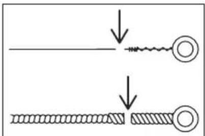
※ Removing all strings at the same time will cause the tremolo attachment angle to change significantly, so we recommend that you replace the strings one at a time. If you remove all strings at the same time, tuning will be easier if you wedge a piece of cloth below the tremolo to secure it so that the tremolo attachment angle won't change signifi cantly.
Memo
- Before you tune, make sure that the string stopper bolts are firmly tightened.
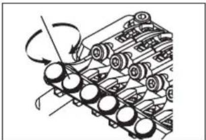
FINE TUNING
Even after you've used the locking nuts to lock the strings, you can use the fi ne tuners to fi ne-tune each string.
The range of adjustment after the strings are locked will be widest if you leave all fi ne-tuning bolts near the center of their adjustable range before you tune.
natural_image
Mechanical assembly diagram showing a rotating component with multiple circular parts (no text or symbols)Overview
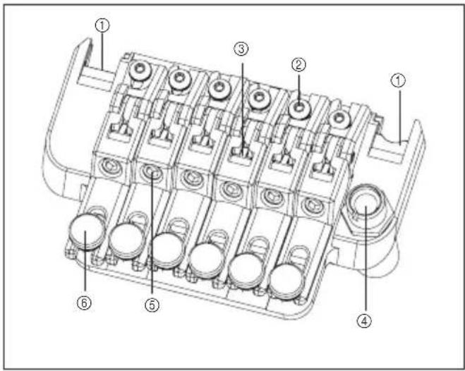
① knife edge
② saddle lock bolt
③ string holder block
④ tremolo arm socket
⑤ string stopper bolt
⑥ fi ne tuning bolt
⑦ main spring
⑧ sub spring
⑨ stopper
⑩ stop rod
⑪ tremolo block
⑫ spring adjustment knob
⑬ tremolo spring
⑭ spring lock
Rear 1
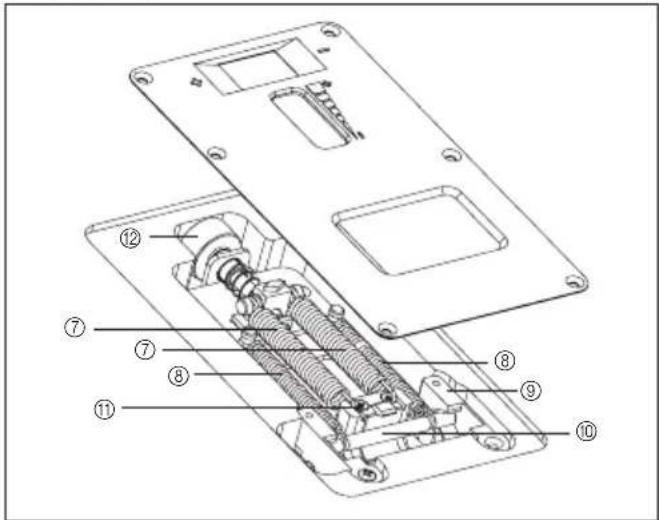
Rear 2
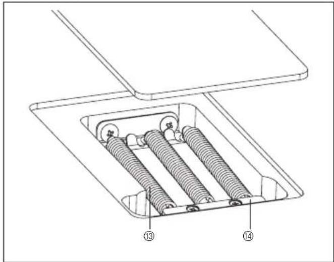
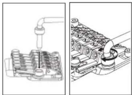
ATTACHING THE TREMOLO ARM
① The tremolo arm employs a one-piece snap-in design with an adjustable torque cap. Insert the tremolo arm into the arm socket of the base plate.
② Tighten the torque adjustment cap to secure the tremolo arm. The tremolo arm will become tighter as you tighten the torque adjustment cap.
natural_image
Technical illustration of engine components with no visible text or symbolsANGLE ADJUSTMENT / ZERO POINT SYSTEM ADJUSTMENT
• Models not equipped with the zero point system
The tremolo attachment angle is adjusted by changing the balance between the string tension and the tension of the tremolo springs installed on the back of the guitar body. You'll obtain the best performance by adjusting the tremolo arm so that it is approximately parallel with the surface of the guitar body.
① With the guitar tuned correctly, check the angle of the tremolo.
② If the tremolo is tilted forward, insert a Philips screwdriver through the slit in the tremolo spring cover on the back of the body, and tighten the screws to increase the tension of the tremolo springs.
③ If the tremolo is tilted toward the rear, loosen the screws to weaken the tension of the tremolo springs.
Because the balance of tension between the strings and the springs will change each time you adjust the tension of the tremolo springs, adjusting the tremolo angle will affect the tuning. You'll need to tune the guitar repeatedly while performing this adjustment.
- Models equipped with the zero point system
The angle at which the tremolo is attached is adjusted by the balance between the tension of the strings and the zero point system installed on the back of the guitar body. The Edge-Zero 2 tremolo bridge is designed so that when the zero point system is correctly adjusted, the tremolo will be approximately parallel with the surface of the guitar body, and will perform optimally when in that state.
When the zero point system is correctly adjusted, the stop rod will be in firm contact with the tremolo block and the stop rod will be touching the stopper.
① With the guitar tuned correctly, check the zero point system.
② If the stop rod is not touching the stopper (i.e., if the tremolo block is pushing up the stop rod), turn the spring adjustment knob located on the back of the body toward the "plus" direction to tighten the main spring.
③ If the tremolo block is not in firm contact with the stop rod (i.e., if the tremolo is tilted toward the rear), turn the spring adjustment knob toward the "minus" direction to loosen the main spring.
TREMOLO SPRING / ZERO POINT SYSTEM
- Models not equipped with the zero point system
When shipped from the factory, the guitar is set up with three tremolo springs installed in parallel.
If the balance of tension between the strings and the tremolo springs has changed significantly, such as when you switch to a different gauge of strings or use a dropped tuning, you may need to change the number of tremolo springs or change the way in which they are installed.
① Use a Philips screwdriver to remove the spring lock.
② If you want to increase the tension, install the outer two tremolo springs diagonally.
③ If you want to decrease the tension, remove the center tremolo spring.
If you want to install four or more tremolo springs, attach them using the screw holes that were being used to attach the spring lock. (It will no longer be possible to attach the spring lock.)
natural_image
Simple line drawing of a mechanical component or tool (no text or symbols)
natural_image
Diagram of a mechanical device with a tool and component, no visible text or symbols
natural_image
Pure electrical circuit lines without any symbols
natural_image
Technical line drawing of a mechanical assembly with spring and housing components (no text or symbols)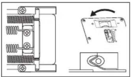
natural_image
Pure mechanical assembly diagram showing spring-loaded components and a right-hand switch mechanism (no text or symbols)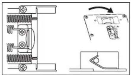
natural_image
Technical line drawing of a mechanical assembly with spring components and a close-up view of a switch mechanism (no text or symbols)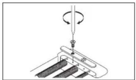
natural_image
Diagram of a mechanical assembly with a rotating component and base plate (no text or symbols)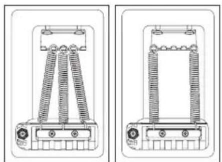
natural_image
Technical line drawings of two mechanical components with spring-like elements and mounting holes (no text or symbols)Memo
Loosen the strings suffi ciently before you install or remove tremolo springs.
Be aware that if you remove all of the springs, the tremolo unit will detach from the guitar.
To reattach the tremolo, insert the knife edge of the tremolo securely into the groove of the stud bolts, and then install the tremolo springs.
- Models equipped with the zero point system
By disabling the zero point system you can use the unit as a conventional fl oating bridge.
When the zero point system is disabled, the angle at which the tremolo is attached will be adjusted by the balance between the tension of the strings and the tension of the main springs attached to the tremolo block.
For optimal performance, adjust the tremolo so that it is approximately parallel with the surface of the guitar body.
① While holding the arm in the upward position (i.e., with the tremolo block away from the stop rod), remove the stop rod and the sub-spring.
② With the guitar tuned correctly, check the angle of the tremolo.
③ If the tremolo is tilted toward the front, turn the spring adjustment knob toward the "plus" direction to tighten the main spring.
④ If the tremolo is tilted toward the rear, turn the spring adjustment knob toward the "minus" direction to loosen the main spring.
※ The tuning will be affected when you adjust the tremolo angle with the zero point system disabled, because the balance between the tension of the strings and the springs will change each time you adjust the tension of the tremolo springs. You'll need to tune repeatedly while making this adjustment.
STUD LOCK
The Edge-Zero2 tremolo bridge uses a stud lock mechanism.
① Insert an Allen wrench (2 mm) through the hole in the top of the stud bolt.
② Turn the stud lock bolt clockwise, tightening it until it contacts the anchor nut and can no longer rotate.
The stud lock will be released when you loosen the stud lock bolt. ※
ADJUSTING THE ACTION
To adjust the height of the entire tremolo unit, use an Allen wrench (3 mm) to turn the stud bolts located at the left and right of the tremolo unit. (It is not possible to make adjustments for each string individually.)

natural_image
Technical line drawing of a mechanical assembly with springs and housing (no text or symbols)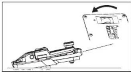
natural_image
Technical line drawing of a mechanical component with an arrow indicating rotation (no text or symbols present)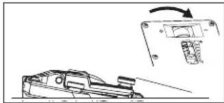
natural_image
Technical line drawing of a mechanical component with an inset showing a rotating component (no text or symbols)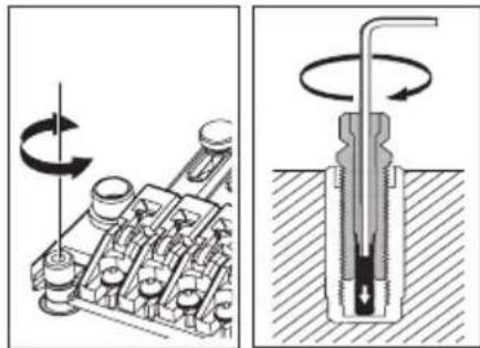
natural_image
Technical illustration of a mechanical assembly with rotating components and a cross-sectional view showing internal structure (no text or symbols)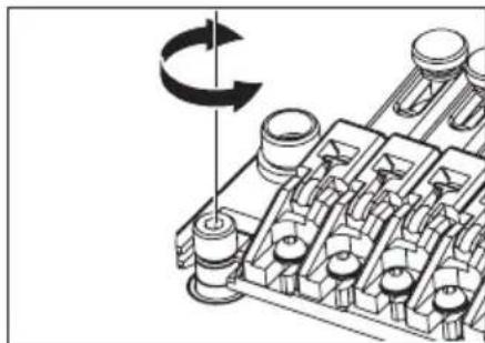
natural_image
Mechanical assembly diagram showing a rotating component with no visible text or symbolsMemo
Before you tune, make sure that the string stopper bolts are firmly tightened.
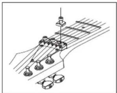
ADJUSTING THE INTONATION
① Use an Allen wrench (3 mm) to loosen the pressure pad bolts of the locking nut, and loosen the strings sufficiently.
② Use an Allen wrench (2 mm) to loosen the saddle lock bolts, and adjust the saddle position.
natural_image
Technical line drawing of a mechanical assembly with no visible text or symbols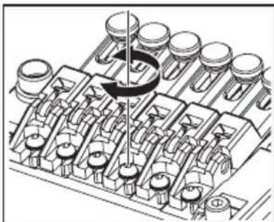
natural_image
Mechanical assembly diagram showing piston and crankshaft components (no text or labels)※ Before checking the intonation, firmly tighten the saddle lock bolts and tune the guitar correctly. When you've fi nished making adjustments, tighten the saddle lock bolts and the pressure pad bolts of the locking nut.
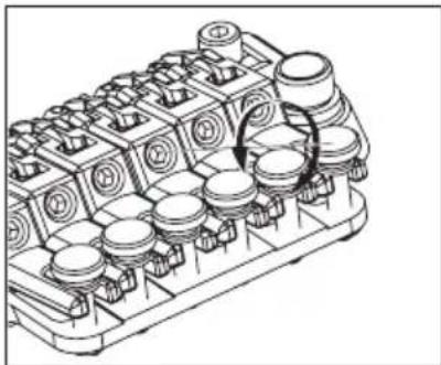
REPLACING THE STRINGS
① Use an Allen wrench (3 mm) to loosen the pressure pad bolts of the locking nut, and remove the string from the tuning peg.
② Use an Allen wrench (3 mm) to loosen the string stopper bolt of the tremolo unit; then pull the string out of the saddle and remove it.
③ Use wire cutters to cut off the ball end of the new string.
④ Insert the tip of the string from which you cut off the ball end between the saddle and the string holder block, and tighten the string stopper bolt to fasten the string.
⑤ Wind the string onto the tuning peg, and tune it.
⑥ When you've finished tuning, tighten the pressure pad bolts of the locking nut.
On tremolo bridges not equipped with the zero cross system, removing all * strings at the same time will cause the tremolo attachment angle to change signifi cantly, so we recommend that you replace the strings one at a time. If you remove all strings at the same time, tuning will be easier if you wedge a piece of cloth below the tremolo to secure it so that the tremolo attachment angle won't change signifi cantly.
natural_image
Technical line drawing of a mechanical component with multiple cylindrical cavities and mounting holes (no text or symbols)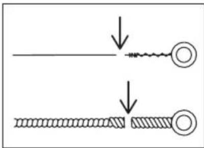
Memo
- Before you tune, make sure that the string stopper bolts are firmly tightened.
FINE TUNING
Even after you've used the locking nuts to lock the strings, you can use the fi ne tuners to fi ne-tune each string.
The range of adjustment after the strings are locked will be widest if you leave all fi ne-tuning bolts near the center of their adjustable range before you tune.
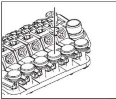
natural_image
Technical line drawing of an internal combustion engine block (no text or symbols)Overview
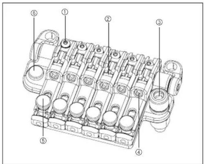
① saddle lock bolt
② string holder block
③ tremolo arm socket
④ string stopper bolt
⑤ fi ne tuning bolt
⑥ intonation adjustment bolt
Rear
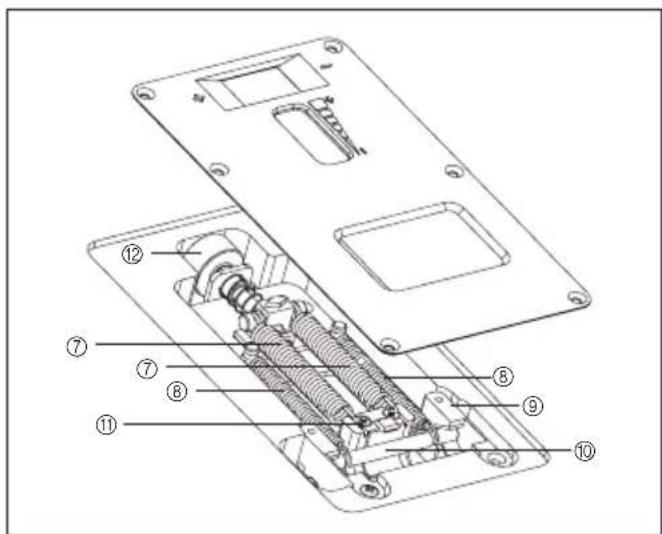
⑦ main spring
⑧ sub spring
⑨ stopper
⑩ stop rod
⑪ tremolo block
⑫ spring adjustment knob
ATTACHING THE TREMOLO ARM
① The tremolo arm employs a one-piece snap-in design with an adjustable torque cap. Insert the tremolo arm into the arm socket of the base plate.
② Tighten the torque adjustment cap to secure the tremolo arm. The tremolo arm will become tighter as you tighten the torque adjustment cap.
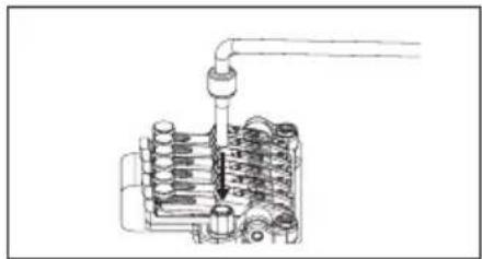
natural_image
Technical line drawing of a mechanical assembly with pipes and components (no text or symbols)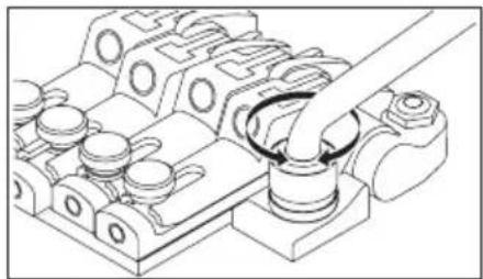
natural_image
Technical line drawing of a mechanical assembly with no visible text or symbolsANGLE ADJUSTMENT / ZERO POINT SYSTEM ADJUSTMENT
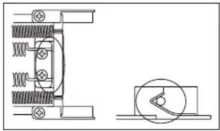
The tremolo attachment angle is adjusted by changing the balance between the string tension and the tension of the zero point system installed on the back of the guitar body. The ZR tremolo bridge is designed so that the tremolo will be approximately parallel with the surface of the guitar body when the zero point system is adjusted correctly, and will perform optimally in this state. When the zero point system is correctly adjusted, the stop rod will be in firm contact with the tremolo block and the stop rod will be touching the stopper.
① With the guitar tuned correctly, check the zero point system.
② If the stop rod is not touching the stopper (i.e., if the tremolo block is pushing up the stop rod), turn the spring adjustment knob located on the back of the body toward the "plus" direction to tighten the main spring.
③ If the tremolo block is not in firm contact with the stop rod (i.e., if the tremolo is tilted toward the rear), turn the spring adjustment knob toward the "minus" direction to loosen the main spring.
natural_image
Technical line drawing of mechanical components with spring and housing (no text or symbols)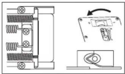
natural_image
Pure electrical circuit lines without any symbols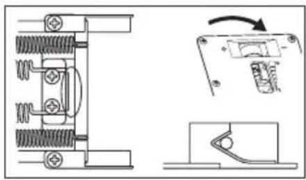
natural_image
Technical line drawing of a mechanical assembly with spring components and a close-up view of a switch mechanism (no text or symbols)DISABLING THE ZERO POINT SYSTEM (USING THE UNIT AS A CONVENTIONAL FLOATING
By disabling the zero point system you can also use the unit as a conventional floating bridge.
When the zero point system is disabled, the angle at which the tremolo is attached will be adjusted by the balance between the tension of the strings and the tension of the main springs attached to the tremolo block.
For optimal performance, adjust the tremolo so that it is approximately parallel with the surface of the guitar body.
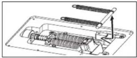
① While holding the arm in the upward position (i.e., with the tremolo block away from the stop rod), remove the stop rod and the sub-spring.
② With the guitar tuned correctly, check the angle of the tremolo.
③ If the tremolo is tilted toward the front, turn the spring adjustment knob toward the "plus" direction to tighten the main spring.
④ If the tremolo is tilted toward the rear, turn the spring adjustment knob toward the "minus" direction to loosen the main spring.
natural_image
Mechanical assembly diagram showing internal components with springs and a handle (no text or labels)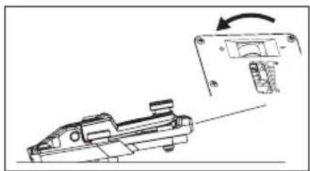
natural_image
Technical line drawing of a mechanical component with an arrow indicating rotation (no text or symbols present)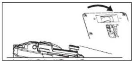
natural_image
Technical line drawing of a mechanical component with an inset showing a rotating component (no text or symbols)※ The tuning will be affected when you adjust the tremolo angle with the zero point system disabled, because the balance between the tension of the strings and the springs will change each time you adjust the tension of the tremolo springs. You'll need to tune repeatedly while making this adjustment.
ADJUSTING THE ACTION
To adjust the height of the entire tremolo unit, use an Allen wrench (3 mm) to turn the stud bolts located at the left and right of the tremolo unit. (It is not possible to make adjustments for each string individually.)
ADJUSTING THE INTONATION
① Remove the intonation adjustment bolts stored inside the tremolo unit, and screw them into the adjustment holes at the back of the saddle until the tip of each bolt contacts the wall of the tremolo unit.
② Use an Allen wrench (2 mm) to loosen the saddle lock bolt, and turn the intonation adjustment bolt to adjust the saddle position.
Before checking the intonation, fi rmly tighten the saddle lock bolts and ※ tune the guitar correctly. Before tuning, use an Allen wrench (3 mm) to loosen the pressure pad bolts of the locking nut. When you've fi nished making adjustments, tighten the saddle lock bolts and the pressure pad bolts of the locking nut, and store the intonation adjustment bolts inside the tremolo unit.
REPLACING THE STRINGS
① Use an Allen wrench (3 mm) to loosen the pressure pad bolts of the locking nut, and remove the string from the tuning peg.
② Use an Allen wrench (3 mm) to loosen the string stopper bolt of the tremolo unit; then pull the string out of the saddle and remove it.
③ Use wire cutters to cut off the ball end of the new string.
④ Insert the tip of the string from which you cut off the ball end between the saddle and the string holder block, and tighten the string stopper bolt to fasten the string.
⑤ Wind the string onto the tuning peg, and tune it.
⑥ When you've finished tuning, tighten the pressure pad bolts of the locking nut.
Memo
Before you tune, make sure that the string stopper bolts are firmly tightened.
FINE TUNING
Even after you've used the locking nuts to lock the strings, you can use the fi ne tuners to fi ne-tune each string.
The range of adjustment after the strings are locked will be widest if you leave all fi ne-tuning bolts near the center of their adjustable range before you tune.

natural_image
Mechanical assembly diagram showing a rotating shaft and housing components (no text or labels)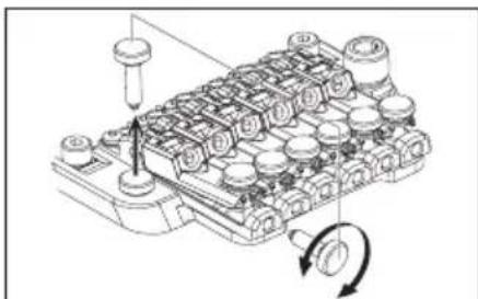
natural_image
Technical diagram of a mechanical component with internal gears and a rotating knob (no text or symbols)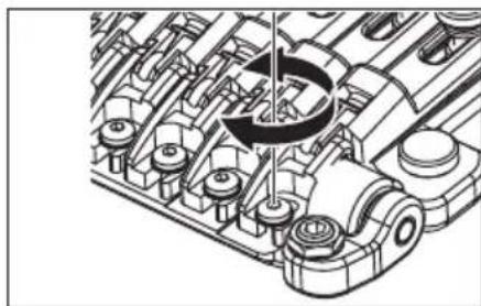
natural_image
Technical illustration of an engine cylinder assembly with internal gears and shafts (no text or symbols)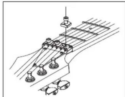
natural_image
Technical line drawing of a guitar fretboard assembly (no text or symbols)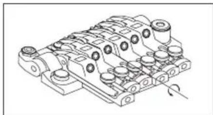
natural_image
Technical line drawing of a mechanical component with multiple cylindrical parts and mounting holes (no text or symbols)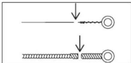
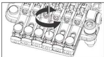
natural_image
Mechanical assembly diagram showing a rotating component with no visible text or symbolsOverview
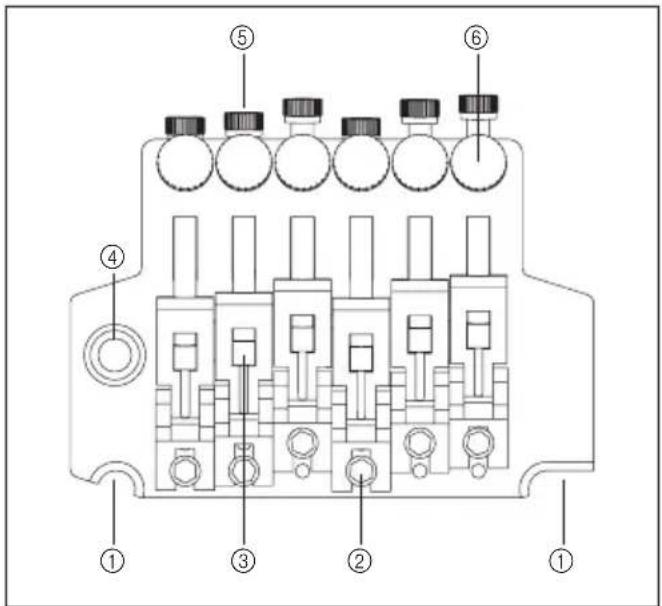
① knife edge
② saddle lock bolt
③ string holder block
④ tremolo arm socket
Rear
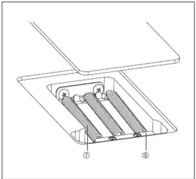
⑤ string stopper bolt
⑥ fi ne tuning bolt
⑦ tremolo spring
⑧ spring lock
ATTACHING THE TREMOLO ARM
① The tremolo arm employs a one-piece snap-in design with an adjustable-torque cap. Insert the tremolo arm into the arm socket of the base plate.
② Tighten the torque adjustment cap to secure the tremolo arm.
The tremolo arm will become tighter as you tighten the torque adjustment cap.
ADJUSTING THE TREMOLO ATTACHMENT ANGLE
The tremolo attachment angle is adjusted by changing the balance between the string tension and the tension of the tremolo springs installed on the back of the guitar body.
You'll obtain the optimal performance by adjusting this so that the tremolo is approximately horizontal to the surface of the guitar body.
① With the guitar tuned correctly, check the angle of the tremolo.
② If the tremolo is tilted toward the front, insert a Philips screwdriver through the slit in the tremolo spring cover on the back of the body, and tighten the screw to increase the tension of the tremolo springs.
③ If the tremolo is tilted toward the rear, loosen the screw to decrease the tension of the tremolo springs.
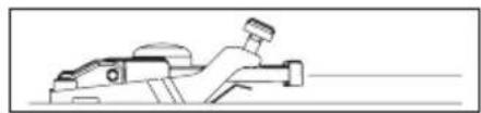
natural_image
Line drawing of a mechanical component or tool (no text or symbols)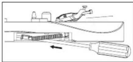
natural_image
Diagram of a mechanical device with a tool and internal components, no visible text or symbols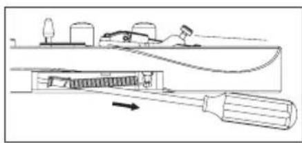
※ The tremolo angle adjustment will affect the tuning, because the balance of tension between the strings and the springs will change each time you adjust the tension of the tremolo springs. You'll need to tune repeatedly while making this adjustment.
TREMOLO SPRINGS
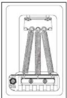
When the guitar is shipped from the factory, it is set up with three tremolo springs installed in parallel.
If the balance of tension between the strings and the tremolo springs has changed signifi cantly, such as when you've switched string gauges or are using a dropped tuning, you may need to change the number of tremolo springs or change the way in which they are installed.
① If you want to increase the tension, install the outer two tremolo springs diagonally.
② If you want to decrease the tension, remove the center tremolo spring.
natural_image
Technical line drawing of a mechanical device with two vertical springs and mounting brackets (no text or symbols)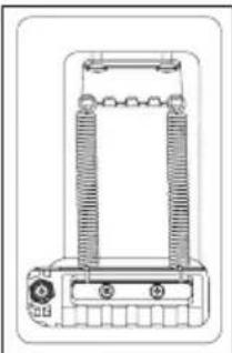
natural_image
Technical line drawing of a mechanical or electrical component with no visible text or symbolsMemo
Loosen the strings suffi ciently before you install or remove tremolo springs.
Be aware that if you remove all of the springs, the tremolo unit will detach from the guitar.
To reattach the tremolo, insert the knife edge of the tremolo securely into the groove of the stud bolts, and then install the tremolo springs.
ADJUSTING THE ACTION
To adjust the height of the entire tremolo unit, use an Allen wrench (3mm) to turn the stud bolts located at the left and right of the tremolo unit. (It is not possible to make adjustments for each string individually.)
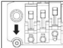
ADJUSTING THE INTONATION
① Use an Allen wrench (3 mm) to loosen the pressure pad bolts of the locking nut, and loosen the strings sufficiently.
② Use an Allen wrench (2 mm) to loosen the saddle lock bolts, and adjust the saddle position.
Before checking the intonation, fi rmly tighten the saddle lock bolts and ※ tune the guitar correctly. When you've fi nished making adjustments, tighten the saddle lock bolts and the pressure pad bolts of the locking nut.
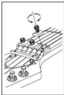
natural_image
Mechanical assembly diagram showing rotating components on a conveyor belt (no text or labels)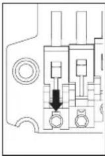
natural_image
Pure mechanical component diagram without any text, numbers, or symbolsREPLACING THE STRINGS
① Use an Allen wrench (3 mm) to loosen the pressure pad bolts of the locking nut, and remove the string from the tuning peg.
② Use an Allen wrench (3 mm) to loosen the string stopper bolt of the tremolo unit; then pull the string out of the saddle and remove it.
③ Use wire cutters to cut off the ball end of the new string.
④ Insert the tip of the string from which you cut off the ball end between the saddle and the string holder block, and tighten the string stopper bolt to fasten the string.
⑤ Wind the string onto the tuning peg, and tune it.
⑥ When you've finished tuning, tighten the pressure pad bolts of the locking nut. Removing all strings at the same time will cause the tremolo attachment ※ angle to change signifi cantly, so we recommend that you replace the strings one at a time. If you remove all strings at the same time, tuning will be easier if you wedge a piece of cloth below the tremolo to secure it so that the tremolo attachment angle won't change signifi cantly.
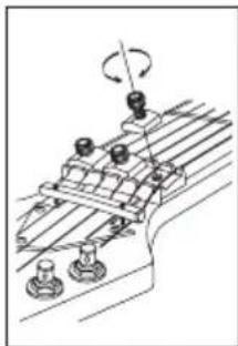
natural_image
Mechanical assembly diagram showing rotating components on a conveyor belt (no text or labels)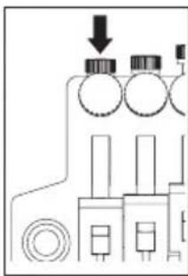
natural_image
Pure electrical circuit lines without any symbols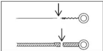
Memo
- Before you tune, make sure that the string stopper bolts are firmly tightened.
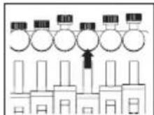
FINE TUNING
Even after you've used the locking nuts to lock the strings, you can use the fi ne tuners to fi ne-tune each string.
The range of adjustment after the strings are locked will be widest if you leave all fine-tuning bolts near the center of their adjustable range before you tune.
Non Locking Tremolo
SynchroniZR
Overview
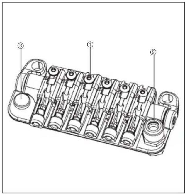
①Saddle lock bolt
②Tremolo arm socket
③Intonation adjustment bolt
Rear
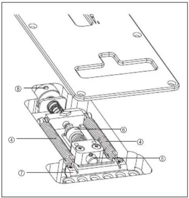
④Tremolo spring
⑤Tremolo block stopper
⑥Tremolo block stopper knob
⑦Tremolo block
⑧Spring adjustment knob
ATTACHING THE TREMOLO ARM
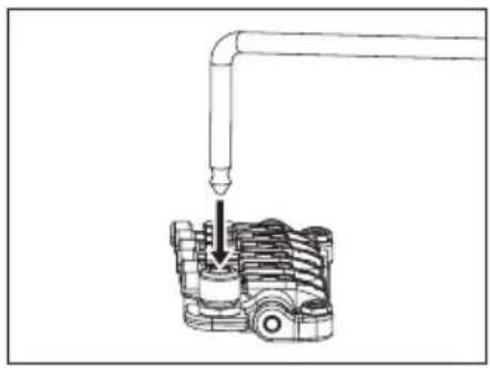
① The tremolo arm employs a snap-in design.
Holding the corner of the tremolo arm, press it firmly into the arm socket of the base plate until it clicks into place.
② The tightness of the tremolo arm can be adjusted by the torque adjustment cap. Turning the cap clockwise will make the arm tighter, and turning it counterclockwise will make the arm looser.
natural_image
Mechanical assembly diagram showing a pipe inserted into a cylindrical component (no text or symbols)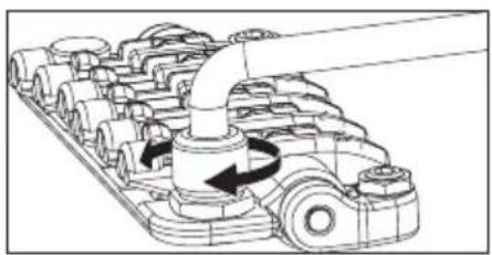
natural_image
Mechanical assembly diagram showing a pipe passing through a multi-cranked gear mechanism (no text or labels)ADJUSTING THE TREMOLO ATTACHMENT ANGLE
The angle at which the tremolo is attached is adjusted by the balance between the tension of the strings and the tension of the tremolo springs installed in the back of the guitar body.
The tremolo will perform optimally when adjusted so that it is approximately parallel with the surface of the guitar body.
① With the guitar tuned correctly, check the angle of the tremolo.
② If the tremolo is tilted forward, turn the spring adjustment knob located on the back of the body toward the "plus" direction to tighten the tremolo springs.
③ If the tremolo is tilted toward the rear, turn the spring adjustment knob toward the "minus" direction to loosen the tremolo springs.
Because the balance of tension between the strings and the springs will change ✉ each time you adjust the tension of the tremolo springs, adjusting the tremolo angle in the floating state will affect the tuning. You'll need to tune the guitar repeatedly while performing this adjustment.
natural_image
Line drawing of a truck with no visible text, numbers, or symbols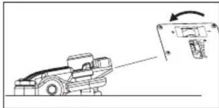
natural_image
Diagram of a truck with an attached device showing a rotation arrow (no text or symbols)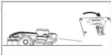
natural_image
Diagram showing a robotic arm interacting with a device, with an arrow indicating motion (no text or symbols present)ARM-UP STOPPER
The SynchroniZR has an arm-up stopper feature. This feature disables the floating state by locking the arm-up range of movement.
① Make sure that the tremolo is adjusted so that it is approximately parallel with the surface of the guitar body.
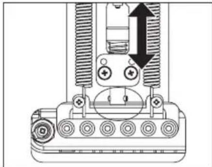
② Remove the tremolo spring cover, and turn the arm-up stopper knob so that the tip of the arm-up stopper contacts the tremolo block.
③ Once again make sure that the tremolo is approximately parallel with the surface of the guitar body, and turn the spring adjustment knob several times in the "plus" direction.
If the tremolo spring tension is too weak, the tremolo block will be ✉ pulled by the strings, possibly causing the tuning to be unstable. If you experience this problem while tuning, turn the spring adjustment knob even farther in the "plus" direction.
natural_image
Technical diagram of a mechanical assembly with no visible text or symbolsSTRING HEIGHT ADJUSTMENT
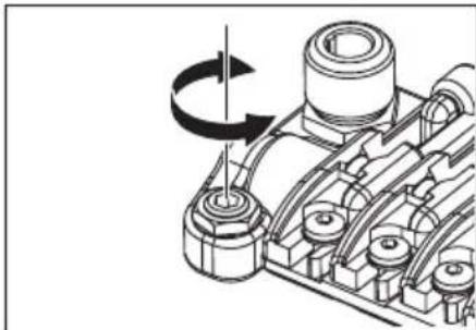
To adjust the string height, adjust the height of the entire tremolo unit by using an Allen wrench (3 mm) to turn the stud bolts located at the left and right of the tremolo unit. (It is not possible to individually adjust the height of each string.)
natural_image
Mechanical assembly diagram showing a rotating shaft and housing components (no text or labels)INTONATION ADJUSTMENT
① Remove the intonation adjustment bolts stored in the tremolo unit, and screw them into the adjustment holes at the rear of the saddle until the bolt tips touch the wall of the tremolo unit.
② Use an Allen wrench (2 mm) to loosen the saddle lock bolt, and turn the intonation adjustment bolt to adjust the saddle position.
Before checking the intonation, firmly tighten the saddle lock bolts and × tune the guitar correctly. When you've finished making adjustments, tighten the saddle lock bolts and the pressure pad bolts of the locking nut, and store the intonation adjustment bolts inside the tremolo unit.
STRING REPLACEMENT
Install new strings by passing them through the tremolo block from the back side of the guitar body.

natural_image
Mechanical assembly diagram showing a chain of gears with a rotating wheel (no text or labels)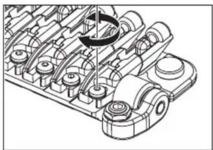
natural_image
Technical illustration of a mechanical assembly with gears and shafts (no text or symbols)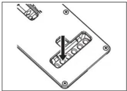
natural_image
Technical diagram showing a mechanical component with an arrow indicating assembly or insertion (no text or symbols present)TREMOLO ARM INSTALLATION
The tremolo arm can be inserted and removed very easily. Insert the arm into the armhole on the tremolo base plate. Pull up on the arm to remove it.
TREMOLO ARM ADJUSTMENT (SAT PRO2)
To adjust the height of the arm, remove the tremolo spring cover from the back of the guitar, and use a 3 mm Allen wrench to turn the height adjustment screw attached to the bottom of the tremolo block. Tightening this in the clockwise direction will raise the height.
ARM ROTATION TORQUE
The rotation torque of the arm can be adjusted by raising the tremolo and inserting a 1.5mm Allen wrench in the screw (A) on the tremolo block, Turning this screw clockwise will tighten the arm torque and turning the screw counter clockwise will loosen the arm torque.
ADJUSTING THE STRING HEIGHT (SAT PRO2)
To adjust the action of each string, use a 1.5 mm Allen wrench to turn the screw on the saddle (C). The overall height can be adjusted on either side of the SAT PRO2 tremolo unit. To adjust the height, use a 3 mm Allen wrench to turn the stud (D) located on either side of the unit. Use caution when adjusting the height of the entire tremolo unit; adjust both sides to the same height to ensure optimum tremolo operation.
ADJUSTING THE STRING HEIGHT (FAT10/SAT10)
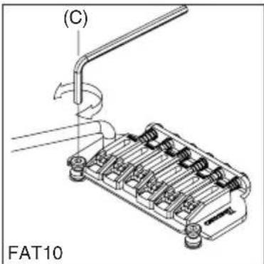
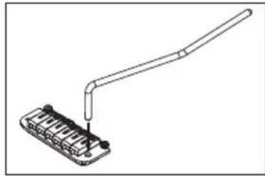
The height adjustment of the tremolo can be raised or lowered by adjusting the pivot studs (C) that the tremolo mounts on. These are located at either side of the front of the bridge. Clockwise lowers the tremolo and counter clockwise raises the tremolo.
natural_image
Pure mechanical diagram of a lever handle attached to a base component (no text or symbols)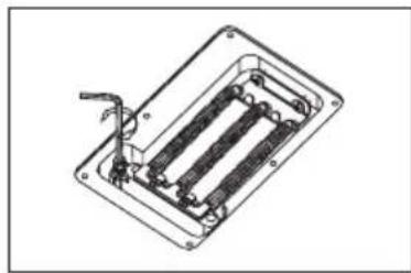
natural_image
Technical line drawing of a mechanical or electrical component with internal parallel lines and a handle (no text or symbols)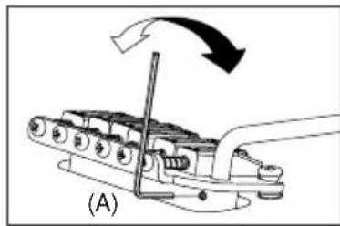
natural_image
Mechanical assembly diagram showing a lever mechanism with motion arrows (no text or symbols)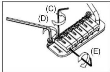
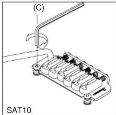
INTONATION ADJUSTMENT (SAT PRO2)
To adjust the intonation, use a 1.5 mm Allen wrench to turn the screw located at the rear of the saddle (E). Turn the screw clockwise to move the saddle toward the rear, or counter-clockwise to move the saddle forward.

INTONATION ADJUSTMENT (FAT10/SAT10)
The intonation can be adjusted by adjusting the saddle forward or backward using a Phillips (+) head screwdriver on the intonation adjustment screw at the rear of the bridge.
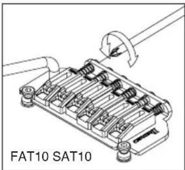
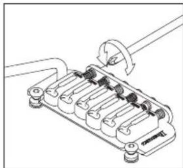
natural_image
Technical line drawing of a mechanical component with no visible text or symbolsADJUSTING THE INTONATION & THE STRING HEIGHT (FAT 6/STD)
The intonation can be adjusted by adjusting the saddle forward or backward using a philips(+) head adjustment screw at the rear of the bridge. String height is controlled by raising or lowering the small allen screws using a wrench on either side of the saddle.
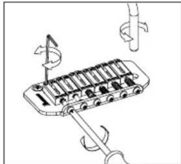
natural_image
Diagram of a mechanical device with rotating components and directional arrows (no text or symbols)REPLACING THE STRINGS
To replace strings, thread the new strings through the string holes located on the back of the guitar. The strings are then threaded through the tremolo block and up and over the saddle.
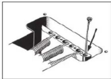
natural_image
Mechanical assembly diagram showing spring-loaded components and a bracket (no text or labels)FAT/SAT (EXPECT FAT6) ADJUSTING THE TREMOLO SPRING
A standard tremolo can be adjusted so that the pitch can be raised when the tremolo arm is pulled up to loosen the tremolo springs located under the tremolo cavity on the back of the guitar. One disadvantage of this procedure is that it can cause the pitch to go sharp if string breaks. To remedy this, adjust the tremolo plate so it sits flush on the body by tightening the tremolo springs. Choose the number and placement of the tremolo springs according to the string gauge and the tremolo adjustment.
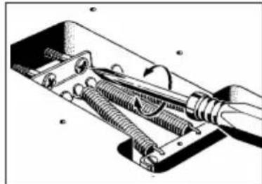
natural_image
Technical illustration of a mechanical assembly with springs and a tool (no text or symbols)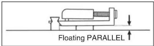
ANBAUTEN
| Multi-tool | Tremolo-hebel | Inbusschlussel | 8-mm-Steck-schlüssel | |||||
| 1.5mm | 2mm 2.5 | mm 3mm | 4mm | |||||
| PREMIUM-Serie Edge-Tremolosteg | ○ | ○ | ||||||
| PREMIUM-Serie Edge-Zero II mit ZPS | ○ | ○ | ||||||
| PREMIUM-Serie ZR-Tremolosteg mit ZPS2 | ○ | ○ | ||||||
| PREMIUM-Serie Tight-End-R-Steg | ○ | |||||||
| Edge-III-Tremolosteg | ○ | ○ | ○ | ○ | ○ | |||
| Edge-Zero II mit ZPS | ○ | ○ | ○ | ○ | ||||
| Edge-Zero II ohne ZPS | ○ | ○ | ○ | ○ | ||||
| FAT6-Tremolosteg | ○ | ○ | ○ | ○ | ||||
| FAT10-Tremolosteg | ○ | ○ | ○ | ○ | ||||
| FX-Edge-III-Steg | ○ | ○ | ○ | |||||
| FX-Edge-III-8-Steg | ○ | ○ | ○ | |||||
| Gibraltar Standardsteg 6/7/8 -Steg | ○ | ○ | ○ | |||||
| SAT10-Tremolosteg | ○ | ○ | ○ | ○ | ||||
| SAT-Pro-II-Tremolosteg | ○ | ○ | ○ | ○ | ||||
| STD-Tremolosteg | ○ | |||||||
| STD-DL-Tremolosteg | ○ | |||||||
| Tight-End-Steg | ○ | ○ | ||||||
| Tight-Tune-Steg | ○ | ○ | ○ | |||||
| ZR-Tremolosteg mit ZPS2 | ○ | ○ | ○ | ○ | ||||
| SynchroniZR-Tremolosteg | ○ | ○ | ||||||
| SAITENHALTER GIBRALTAR 08 / QUICK CHANGE 08 TAILPIECE | ○ | |||||||
natural_image
Technical line drawing of two mechanical fasteners with hexagonal bases and mounting holes (no text or symbols)Hinweis
natural_image
Line drawing of a hand playing guitar chord with fretboard (no text or symbols)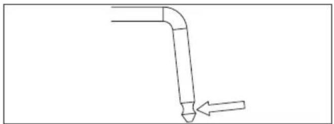
natural_image
Simple line drawing of a bent pipe or duct with an arrow pointing to it (no text or symbols)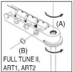
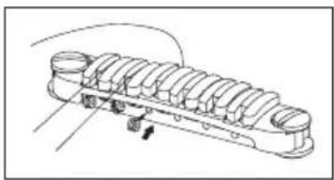
natural_image
Technical line drawing of a mechanical component with multiple cylindrical parts and mounting holes (no text or symbols)ERSETZEN DER SAITEN: CB3
natural_image
Diagram showing a screwdriver inserted into a mechanical component with rotating arrows indicating motion (no text or symbols present)GIBRALTAR STANDARDSTEG (7-SAITIGE / 8-SAITIGE MODELLE)
natural_image
Technical line drawing of a mechanical component with labeled dimensions A and B (no text or symbols beyond labels)Vintage Vibrato
natural_image
Technical diagram of a mechanical component with rotational arrow indicating motion (no text or symbols)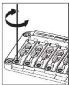
natural_image
Mechanical component diagram showing a rotating shaft assembly with multiple slots and a curved arrow indicating rotation (no text or symbols)natural_image
Technical diagram of a mechanical component with rotational arrow indicating motion (no text or symbols)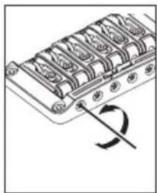
natural_image
Diagram of a mechanical component with a curved arrow indicating rotation (no text or symbols)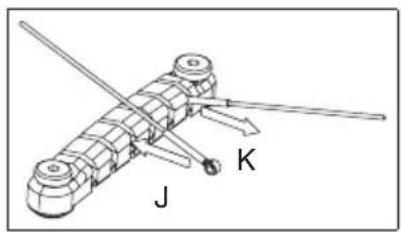
natural_image
Mechanical assembly diagram showing a linkage mechanism with labeled components J and K (no text or symbols beyond labels)Locking Bridge
FX-EDGE-III-/FX-EDGE-III-8-STEG
FX Edge III
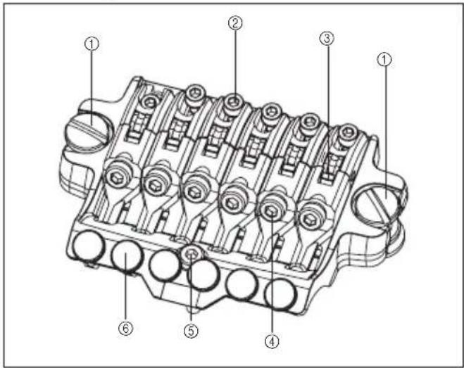
natural_image
Technical line drawing of an internal combustion engine block with no visible text or symbolsnatural_image
Technical line drawing of a mechanical assembly with no visible text or symbolsWECHSELN DER SAITEN
natural_image
Technical line drawing of an internal combustion engine cylinder (no text or labels)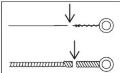
natural_image
Diagram showing two stages of a mechanical or electrical component with arrows indicating process direction (no text or symbols)Hinweis
natural_image
Technical line drawing of a mechanical component with multiple cylindrical parts and a rotation arrow (no text or symbols)Locking Bridge
EDGE-TREMOLOSTEG
Edge
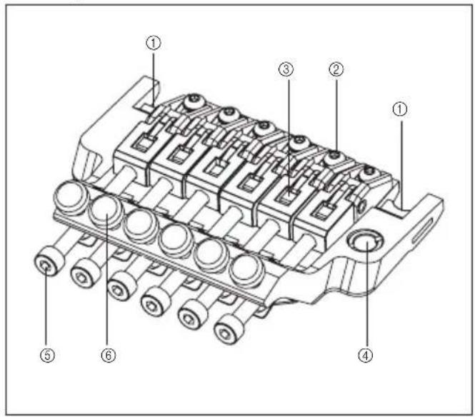
Lo-Pro Edge
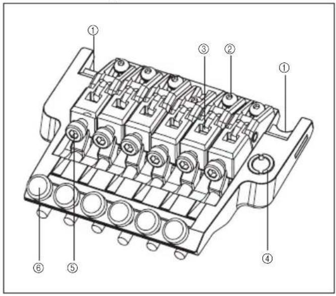
Rückseite
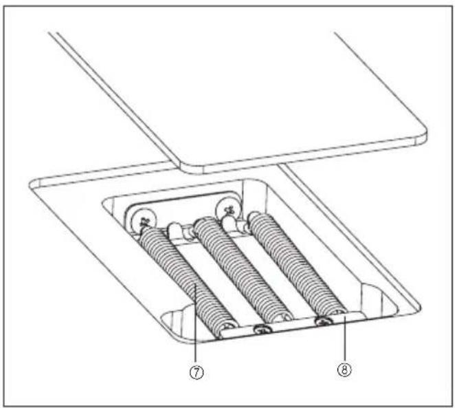
natural_image
Technical line drawing of a mechanical assembly with springs and housing (no text or symbols)natural_image
Technical line drawing of a mechanical component with threaded ends and a cylindrical shaft (no text or symbols)natural_image
Line drawing of a mechanical component or tool, possibly a cutting or assembly, with no visible text or symbols.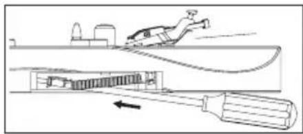
natural_image
Diagram of a person climbing over a cable with a tool inserted, showing mechanical components and motion direction (no text or symbols)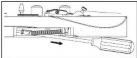
natural_image
Diagram of a mechanical device with a tool inserted into a housing, showing internal components and motion direction (no text or symbols)TREMOLOFEDERN
natural_image
Diagram of a mechanical assembly with rotating components and a pointer (no text or symbols)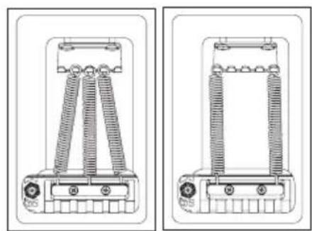
natural_image
Technical line drawings of two mechanical components with coiled springs and mounting holes (no text or symbols)Hinweis
natural_image
Technical line drawing of a mechanical assembly with no visible text or symbols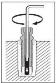
natural_image
Cross-sectional diagram of a mechanical component with rotating shaft and base, no text or symbols presentnatural_image
Technical line drawing of a mechanical component with multiple ports and rotating arms (no text or symbols)Hinweis
natural_image
Technical diagram of a mechanical assembly with rotating components (no text or symbols)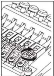
natural_image
Technical line drawing of a mechanical assembly with multiple cylindrical components and a central circular component (no text or symbols)WECHSELN DER SAITEN
natural_image
Technical line drawing of a mechanical assembly with rotating components (no text or symbols)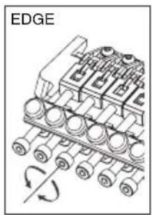
natural_image
Mechanical assembly diagram showing a gear-like component with rotational arrows (no text or symbols)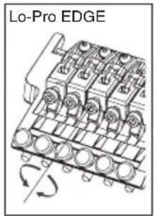

Hinweis
natural_image
Mechanical assembly diagram showing a pipe inserted into a grid-like component (no text or symbols visible)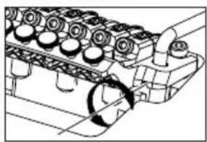
natural_image
Technical line drawing of an engine cylinder head assembly with no visible text or symbols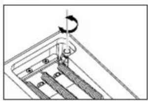
natural_image
Diagram of a mechanical assembly with a hand holding a rotating component (no text or symbols visible)Hinweis
natural_image
Diagram of a mechanical assembly with a rotating component and a base plate (no text or symbols)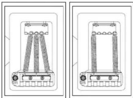
natural_image
Technical line drawing of two mechanical components with coiled springs and mounting brackets (no text or symbols)Hinweis
natural_image
Mechanical assembly diagram showing gear and shaft components with rotational motion arrows (no text or labels)natural_image
Technical line drawing of a mechanical assembly with rotating components (no text or symbols)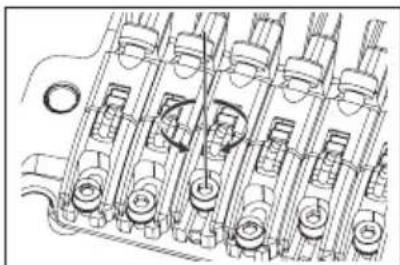
natural_image
Technical line drawing of a mechanical assembly with multiple cylindrical components and mounting holes (no text or symbols)natural_image
Technical line drawing of an engine cylinder assembly with no visible text or symbols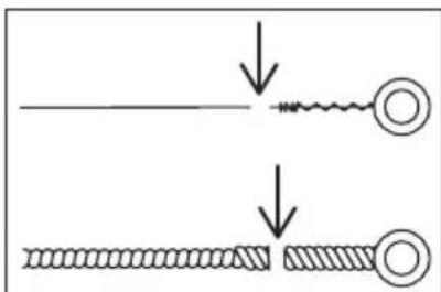
natural_image
Mechanical assembly diagram showing a rotating mechanism with no visible text or symbolsÜberblick
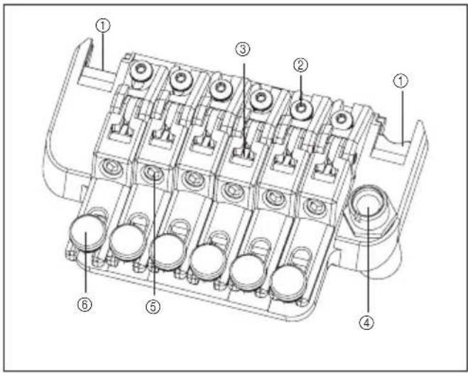
Rückseite 2
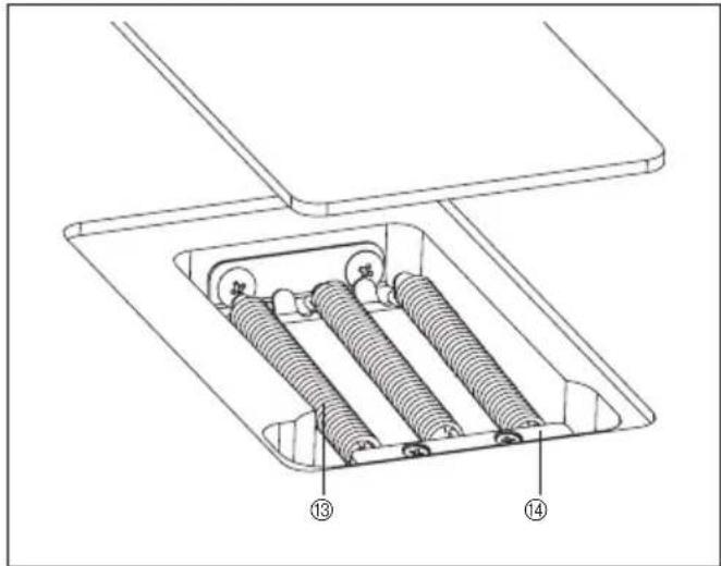
MONTAGE DES TREMOLOHEBELS
natural_image
Technical line drawings of mechanical components, one showing a pipe inserted into a housing and the other showing a valve assembly (no text or symbols present)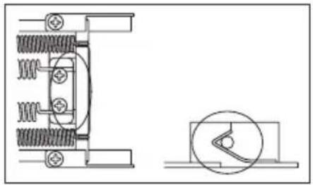
natural_image
Technical line drawing of a mechanical assembly with spring and housing components (no text or symbols)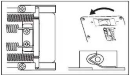
natural_image
Technical diagram showing mechanical components and a close-up of a device with a rotating arrow (no text or symbols)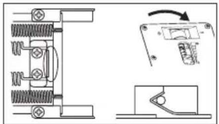
natural_image
Technical line drawing of a mechanical component with spring and housing, showing assembly and disassembly views (no text or symbols)
natural_image
Diagram of a mechanical assembly with a rotating component and base plate (no text or symbols)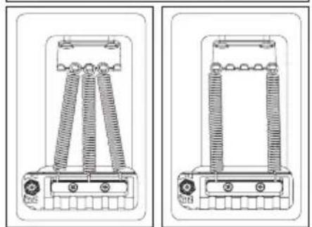
natural_image
Technical line drawings of two mechanical components with spring-like elements and mounting holes (no text or symbols)Hinweis
natural_image
Technical line drawing of a mechanical assembly with springs and housing (no text or symbols)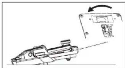
natural_image
Technical line drawing of a mechanical component with an arrow indicating rotation (no text or symbols present)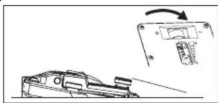
natural_image
Technical line drawing of a mechanical component with an arrow indicating rotation (no text or symbols)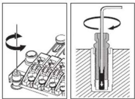
natural_image
Mechanical assembly diagram showing a rotating component and a cross-sectional view of a threaded fastener (no text or labels)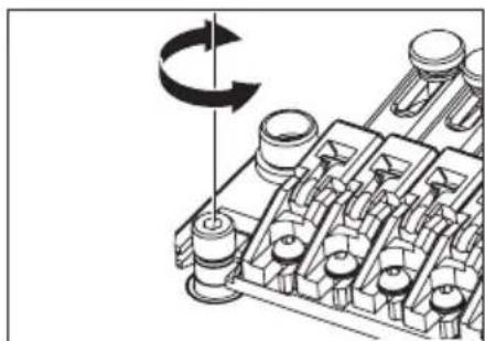
natural_image
Mechanical assembly diagram showing a rotating component with no visible text or symbolsHinweis
natural_image
Technical line drawing of a mechanical assembly with four components and diagonal guide lines (no text or symbols)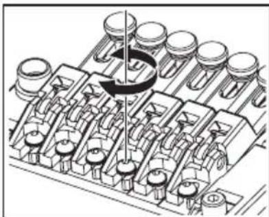
natural_image
Mechanical assembly diagram showing piston and crankshaft components (no text or labels)natural_image
Technical line drawing of a mechanical component with multiple cylindrical cavities and mounting brackets (no text or symbols)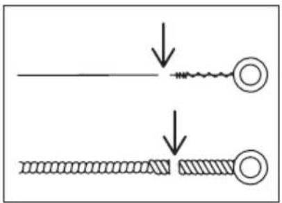
Hinweis
natural_image
Technical line drawing of an internal combustion engine cylinder head assembly (no text or labels)Überblick
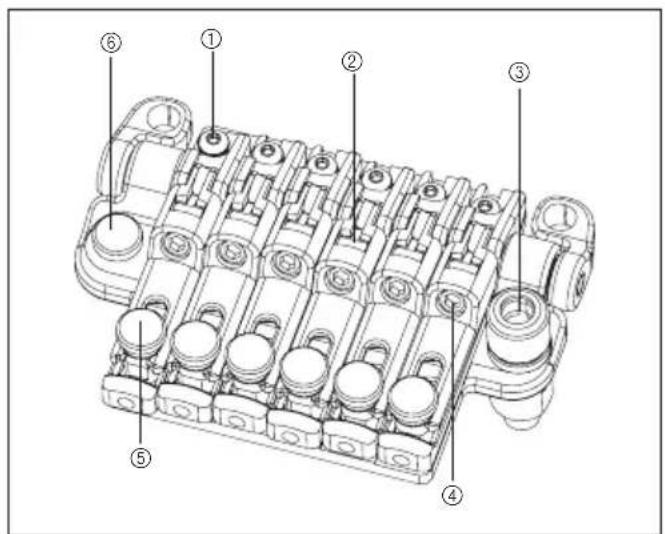
natural_image
Technical diagram of a mechanical assembly with pipes and components (no text or labels)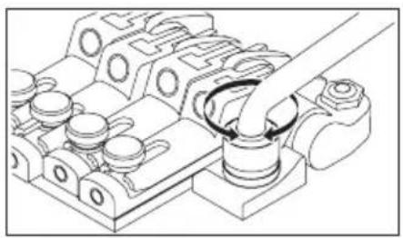
natural_image
Technical line drawing of a mechanical assembly with no visible text or symbolsDEAKTIVIEREN DES NULLPUNKTSYSTEMS (VERWENDUNG ALS HERKÖMMLICHES SCHWEBENDES TREMOLO)
natural_image
Mechanical assembly diagram showing a rotating component with no visible text or symbols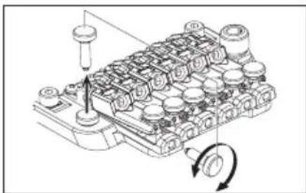
natural_image
Technical line drawing of a mechanical assembly with no visible text or symbols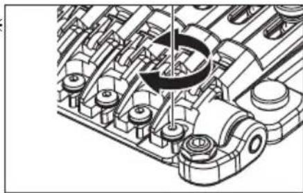
natural_image
Technical line drawing of a mechanical assembly with gears and shafts (no text or symbols)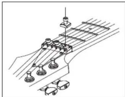
natural_image
Technical line drawing of a mechanical assembly with no visible text or symbols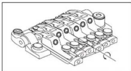
natural_image
Technical line drawing of a mechanical component with multiple cylindrical parts and mounting holes (no text or symbols)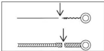
natural_image
Diagram showing two stages of a mechanical or electrical component with arrows indicating motion (no text or symbols)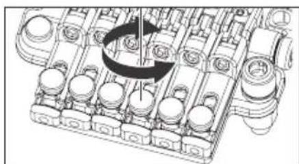
natural_image
Mechanical assembly diagram showing a rotating component with no visible text or symbolsGesamtansicht
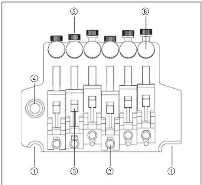
natural_image
Line drawing of a mechanical component or tool (no text or symbols)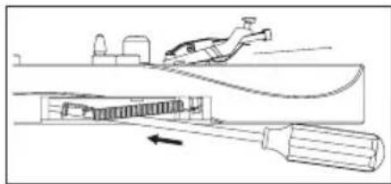
natural_image
Diagram of a mechanical device with a tool and internal components, no visible text or symbols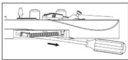
natural_image
Technical line drawing of a mechanical device with spring-like components and mounting brackets (no text or symbols)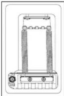
natural_image
Technical line drawing of a mechanical or electrical component with no visible text or symbolsHinweis
natural_image
Mechanical assembly diagram showing rotating components on a conveyor belt (no text or labels)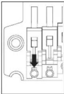
natural_image
Pure electrical circuit lines without any symbolsWECHSELN DER SAITEN
natural_image
Technical line drawing of a mechanical assembly with rotating components (no text or symbols)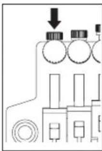
natural_image
Pure electrical circuit lines without any symbols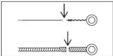
Hinweis
④Tremolofeder
⑤Tremoloblock Stopper
⑥Tremoloblock Stopperschraube
⑦Tremoloblock
⑧Federeinstellknopf
MONTAGE DES TREMOLOHEBELS
natural_image
Mechanical assembly diagram showing a pipe inserted into a component (no text or symbols)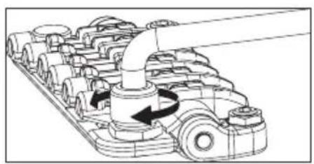
natural_image
Mechanical assembly diagram showing gear and shaft components with directional arrows (no text or labels)natural_image
Line drawing of a truck with roof and side-mounted sensors (no text or symbols)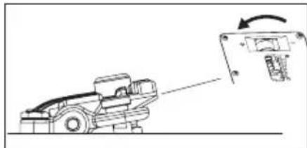
natural_image
Diagram of a truck with an arrow indicating motion, showing a vehicle and its internal components (no text or symbols present)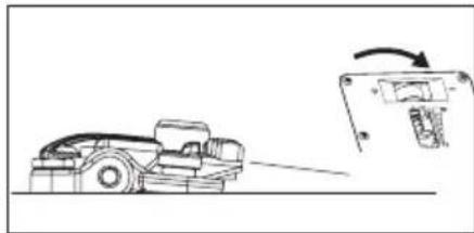
natural_image
Diagram showing a vehicle on a road with an arrow indicating motion or change, next to a mechanical component (no text or symbols present)STOPPFUNKTION BEI ANGEHOBENEM HEBEL
natural_image
Mechanical assembly diagram showing a clamping device with threaded components and directional arrows indicating motion (no text or symbols)natural_image
Mechanical assembly diagram showing a rotating shaft and housing components (no text or labels)natural_image
Mechanical assembly diagram showing a conveyor belt system with rotating wheel and connecting rod (no text or labels)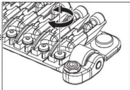
natural_image
Technical line drawing of a mechanical assembly with gears and shafts (no text or symbols)WECHSELN DER SAITEN
natural_image
Technical line drawing of a mechanical component with a downward arrow indicating a feature (no text or symbols present)TREMOLOARM-INSTALLATION
natural_image
Pure mechanical diagram showing a lever and base component without any text, numbers, or symbols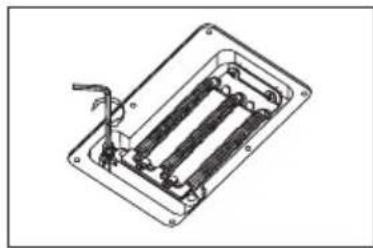
natural_image
Technical line drawing of a mechanical or electrical component with internal parallel slots and a handle (no text or symbols)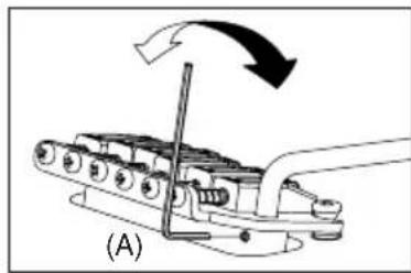
natural_image
Mechanical assembly diagram showing a lever mechanism with motion arrows (no text or symbols)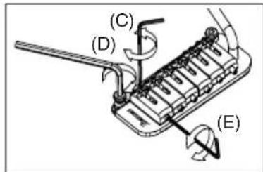
natural_image
Technical line drawing of a mechanical component with no visible text or symbolsnatural_image
Diagram of a mechanical device with rotating components and directional arrows indicating motion (no text or symbols)ERSETZEN DER SAITEN
natural_image
Mechanical assembly diagram showing spring-loaded components and a bracket (no text or labels)FAT/SAT (AUSGENOMMEN FAT6) EINSTELLEN DER TREMOLOFEDER
natural_image
Technical illustration of a mechanical assembly with springs and a tool (no text or symbols)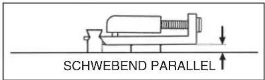
FIXATIONS
| Multioutils | Tige de vibrato | Clé Allen | Clé à douille 8 mm | |||||
| 1.5mm | 2mm 2.5mm | 3mm | 4mm | |||||
| Gamme PREMIUM - Chevalet vibrato Edge | ○ | ○ | ||||||
| Gamme PREMIUM - Edge-Zero II avec ZPS | ○ | ○ | ||||||
| Gamme PREMIUM - Chevalet vibrato ZR avec ZPS2 | ○ | ○ | ||||||
| Gamme PREMIUM - Chevalet Tight-End R | ○ | |||||||
| Chevalet vibrato Edge III | ○ | ○ | ○ | ○ | ○ | |||
| Edge-Zero II avec ZPS | ○ | ○ | ○ | ○ | ||||
| Edge-Zero II sans ZPS | ○ | ○ | ○ | ○ | ||||
| Chevalet vibrato FAT6 | ○ | ○ | ○ | ○ | ||||
| Chevalet vibrato FAT10 | ○ | ○ | ○ | ○ | ||||
| Chevalet FX Edge III | ○ | ○ | ○ | |||||
| Chevalet FX Edge III-8 | ○ | ○ | ○ | |||||
| Chevalet Gibraltar standard 6/7/8 | ○ | ○ | ○ | |||||
| Chevalet vibrato SAT10 | ○ | ○ | ○ | ○ | ||||
| Chevalet vibrato SAT-Pro II | ○ | ○ | ○ ○ | |||||
| Chevalet vibrato STD | ○ | |||||||
| Chevalet vibrato STD-DL | ○ | |||||||
| Chevalet Tight-End | ○ | ○ | ||||||
| Chevalet Tight-Tune | ○ | ○ ○ | ||||||
| Chevalet vibrato ZR avec ZPS2 | ○ | ○ | ○ ○ | |||||
| Chevalet vibrato SynchroniZR | ○ | ○ | ||||||
| CHEVALET GIBRALTAR 08/CORDIER QUICK CHANGE 08 | ○ | |||||||
REPLACEMENT DES CORDES
natural_image
Technical line drawing of two mechanical components with threaded ends and a central hole, shown without any text or symbols.Mémo
natural_image
Line drawing of a hand playing guitar chord with fretboard and fretstock (no text or symbols)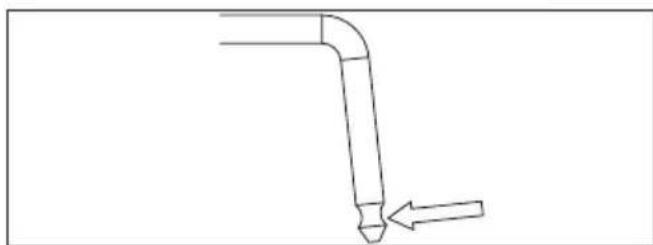
natural_image
Simple line drawing of a bent pipe with an arrow pointing to it (no text or symbols)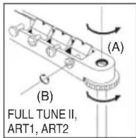
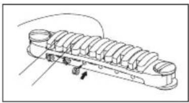
natural_image
Technical line drawing of a multi-layered mechanical component with no visible text or symbolsREEMPLACEMENT DES CORDES : CB3
natural_image
Diagram of a screwdriver working on an electronic component with rotating arrows indicating motion (no text or symbols present)CHEVALET À TABLE BOMBÉE RÉGLABLE
natural_image
Technical line drawing of a mechanical component with labeled dimensions A and B (no text or symbols beyond labels)Vibrato Vintage
natural_image
Technical diagram of a mechanical assembly with rotating components (no text or symbols)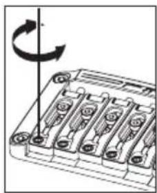
natural_image
Diagram of a battery pack with rotating arrow indicating rotation (no text or symbols)RÉGLAGE DE L'INTONATION
natural_image
Technical line drawing of a mechanical component with a rotating arrow indicating rotation (no text or symbols)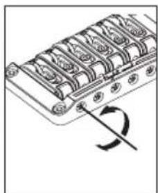
natural_image
Diagram of a mechanical component with multiple cylindrical parts and a curved arrow indicating rotation (no text or symbols)REPLACEMENT DES CORDES
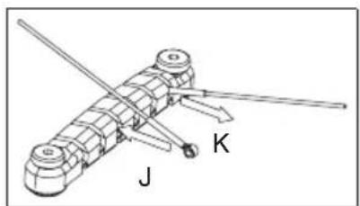
natural_image
Mechanical device with labeled components J and K, no readable text or symbols beyond labelsLocking Bridge
CHEVALET FX EDGE III/FX EDGE III-8
FX Edge
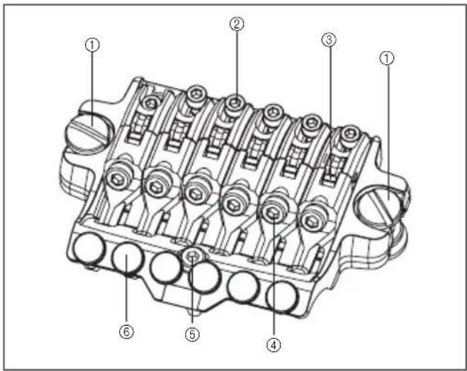
natural_image
Technical diagram of an internal combustion engine cylinder with no visible text or symbolsnatural_image
Technical illustration of mechanical components with no visible text or symbolsREMPLACEMENT DES CORDES
natural_image
Technical line drawing of a mechanical component with multiple cylindrical cavities and mounting holes (no text or symbols)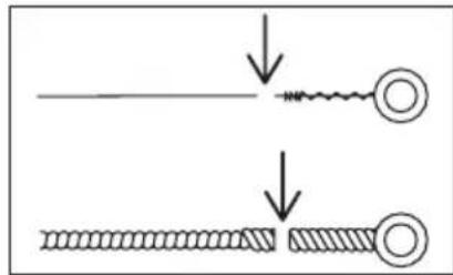
Mémo
natural_image
Technical line drawing of a mechanical component with multiple cylindrical parts and a rotating knob (no text or symbols)Locking Tremolos
CHEVALET VIBRATO EDGE
Edge
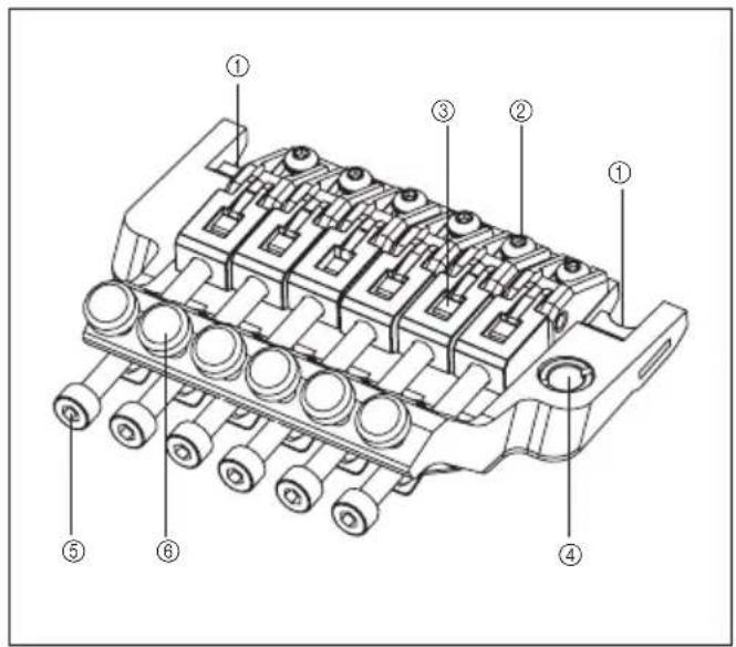
Lo-Pro Edge
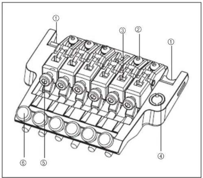
Arrière
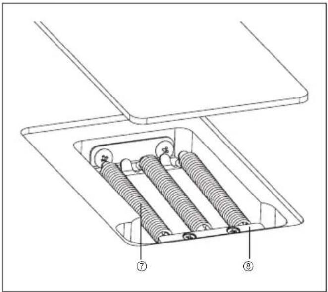
natural_image
Technical line drawing of a mechanical assembly with springs and housing (no text or symbols)natural_image
Technical line drawing of a mechanical component with no visible text or symbolsRÉGLAGE DE L'ANGLE D'ATTAQUE DU VIBRATO
natural_image
Line drawing of a mechanical component or tool, possibly a valve or actuator, with no visible text or symbols.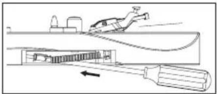
natural_image
Diagram of a mechanical device with a tool and spring, showing internal components and motion direction (no text or symbols)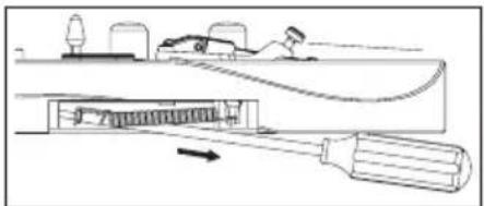
natural_image
Diagram of a mechanical assembly with a rotating component and a base plate (no text or symbols)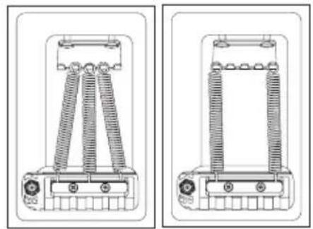
natural_image
Technical line drawing of two electrical insulator components with coiled spring and terminal blocks (no text or symbols)Mémo
natural_image
Technical line drawing of a mechanical assembly with gears and shafts (no text or symbols)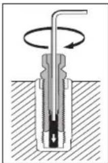
natural_image
Cross-sectional diagram of a mechanical component with rotational motion arrows (no text or labels)natural_image
Technical line drawing of a mechanical component with multiple slots and mounting holes (no text or symbols)Mémo
natural_image
Mechanical assembly diagram showing rotating components on a curved surface (no text or labels)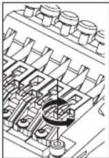
natural_image
Technical line drawing of a mechanical assembly with multiple components and a central rotating component (no text or symbols)REPLACEMENT DES CORDES
natural_image
Technical line drawing of a mechanical assembly with rotating components and connecting rods (no text or symbols)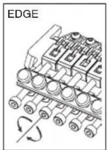
natural_image
Diagram of an industrial conveyor system with rotating components and a labeled edge (no text or symbols beyond label)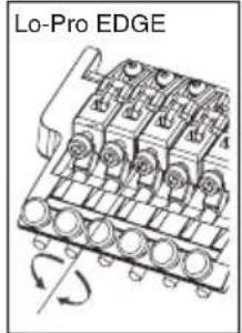
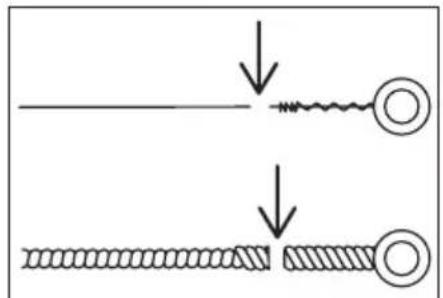
Mémo
natural_image
Mechanical assembly diagram showing a pipe inserted into a grid of components (no text or labels visible)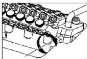
natural_image
Technical line drawing of an engine cylinder head assembly with no visible text or symbols
natural_image
Diagram of a mechanical assembly with a rotating component and housing (no text or symbols)Mémo
natural_image
Pure mechanical component diagram without any text, numbers, or symbols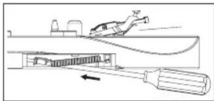
natural_image
Diagram of a mechanical device with a tool and component, showing motion or assembly (no text or symbols)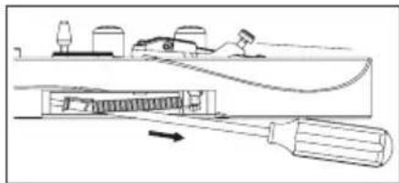
natural_image
Diagram of a mechanical device with a tool and internal components, no visible text or symbolsnatural_image
Mechanical assembly diagram showing a tool interacting with a base plate (no text or symbols visible)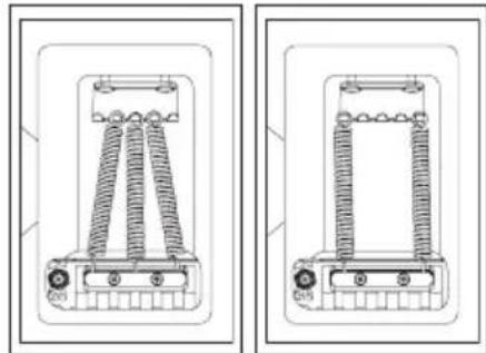
natural_image
Technical line drawing of a mechanical device with coiled spring and mounting base (no text or symbols)Mémo
natural_image
Mechanical assembly diagram showing a rotating mechanism with multiple components and a central shaft (no text or symbols)RÉGLAGE DE L'INTONATION
natural_image
Technical line drawing of a mechanical assembly with rotating components (no text or symbols)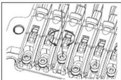
natural_image
Technical line drawing of internal mechanical components (no text or symbols)REPLACEMENT DES CORDES
natural_image
Technical line drawing of an engine cylinder assembly (no text or symbols)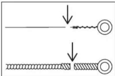
natural_image
Mechanical assembly diagram showing a rotating engine component with no visible text or symbolsArrière 2
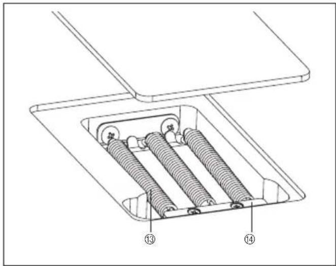
natural_image
Technical line drawing of a mechanical assembly with numbered components (no text or symbols)FIXATION DE LA TIGE DE VIBRATO
natural_image
Technical illustration of mechanical assembly with pipe and valve components (no text or symbols)ZERO POINT
natural_image
Pure mechanical component diagram without any text, numbers, or symbols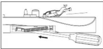
natural_image
Diagram of a mechanical device with a tool inserted into a housing, showing internal components and motion direction (no text or symbols)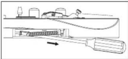
natural_image
Technical line drawing of a mechanical assembly with no visible text or symbols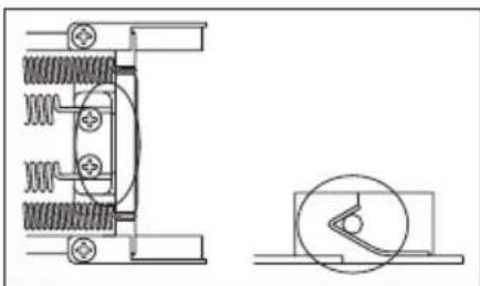
natural_image
Technical line drawing of a mechanical assembly with spring and housing components (no text or symbols)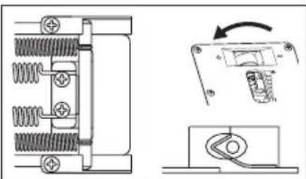
natural_image
Technical diagram showing mechanical components with spring and housing, including a close-up of a switch mechanism (no text or labels)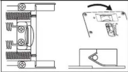
natural_image
Technical line drawing of a mechanical assembly with spring-loaded components and a close-up view of a switch mechanism (no text or symbols)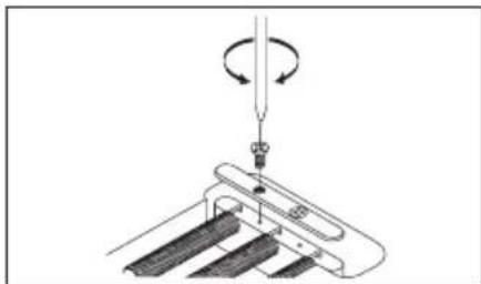
natural_image
Diagram of a mechanical assembly with a rotating component and base plates (no text or symbols)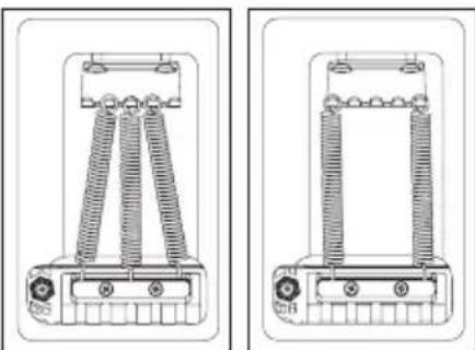
natural_image
Technical line drawings of two electrical components with coiled and straight wires (no text or symbols)Mémo
natural_image
Technical line drawing of an internal mechanical assembly with springs and housing (no text or symbols)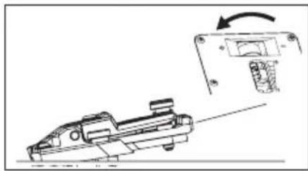
natural_image
Technical line drawing of a mechanical component with an arrow indicating rotation (no text or symbols)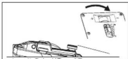
natural_image
Diagram showing a vehicle on a road with an inset view of a mechanical component (no text or symbols)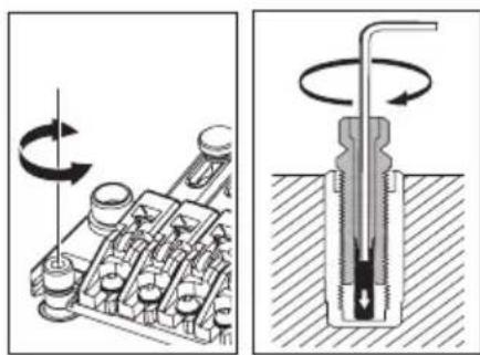
natural_image
Mechanical assembly diagram showing a rotating component and a cross-sectional view of a mechanical component (no text or symbols)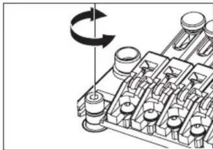
natural_image
Mechanical assembly diagram showing a rotating component with no visible text or symbolsMémo
natural_image
Technical line drawing of a mechanical assembly with no visible text or symbols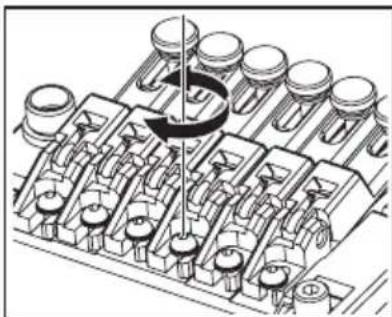
natural_image
Technical illustration of a mechanical assembly with multiple components and a central rotating element (no text or symbols)natural_image
Technical line drawing of a mechanical component with multiple cylindrical cavities and mounting brackets (no text or symbols)
Mémo
natural_image
Technical line drawing of an internal combustion engine block assembly (no text or symbols)Vue d'ensemble

natural_image
Mechanical assembly diagram showing a valve inserted into a multi-chambered engine block (no text or labels)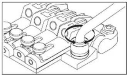
natural_image
Technical line drawing of a mechanical assembly with no visible text or symbolsRÉGLAGE DE L'ANGLE DU VIBRATO/RÉGLAGE DU SYSTÈME ZERO POINT
natural_image
Technical line drawing of a mechanical assembly with spring and housing components (no text or symbols)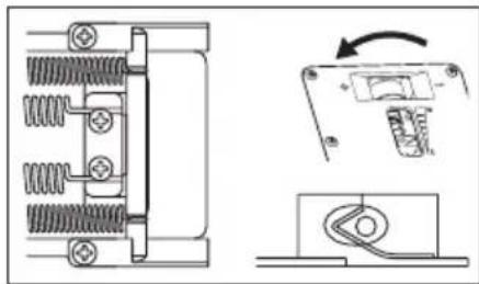
natural_image
Technical line drawing of a mechanical component with spring and housing, showing assembly steps (no text or symbols)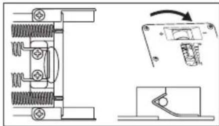
natural_image
Technical line drawing of a mechanical assembly with spring and housing components, showing exploded and assembled views (no text or symbols)DÉSACTIVATION DU SYSTÈME ZERO POINT (UTILISATION DE L'UNITÉ COMME UN VIBRATO FL OTTANT TRADITIONNEL)
natural_image
Technical diagram of an internal mechanical assembly with springs and housing (no text or labels)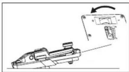
natural_image
Technical line drawing of a mechanical component with an arrow indicating rotation (no text or symbols present)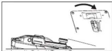
natural_image
Technical line drawing of a mechanical component with an arrow indicating rotation (no text or symbols)REPLACEMENT DES CORDES
natural_image
Mechanical assembly diagram showing a rotating component with no visible text or symbols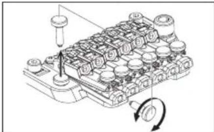
natural_image
Technical diagram of a mechanical component with no visible text or symbols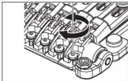
natural_image
Technical illustration of an engine cylinder assembly (no text or symbols visible)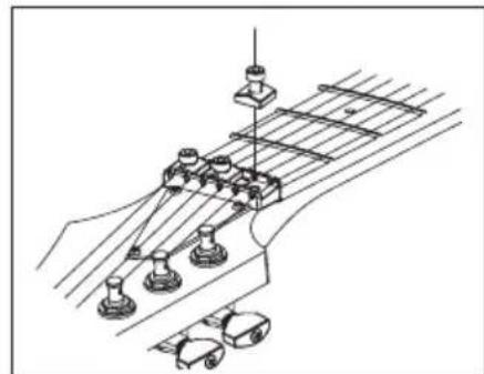
natural_image
Pure electrical circuit lines without any symbols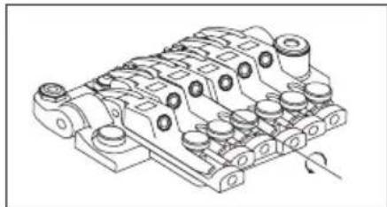
natural_image
Technical line drawing of a mechanical component with multiple cylindrical features and mounting holes (no text or symbols)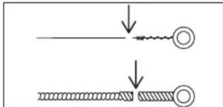
natural_image
Diagram showing two steps of a mechanical or electrical component with no visible text or symbols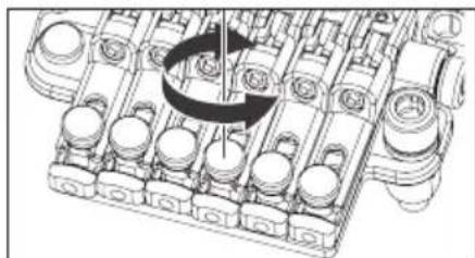
natural_image
Technical line drawing of a mechanical assembly with no visible text or symbolsPrésentation
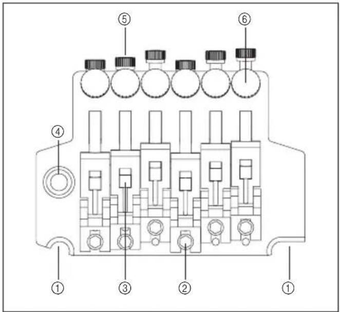
natural_image
Line drawing of a mechanical component or tool (no text or symbols)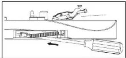
natural_image
Technical line drawing of a mechanical assembly with a tool and component, no visible text or symbols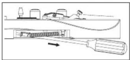
natural_image
Technical line drawing of a mechanical assembly with a tool and component, no visible text or symbolsnatural_image
Pure mechanical assembly diagram showing piston and crankshaft components without any text or symbolsRÉGLAGE DE L'INTONATION
REPLACEMENT DES CORDES
natural_image
Mechanical assembly diagram showing rotating components on a conveyor belt (no text or labels)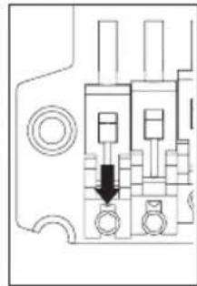
natural_image
Pure electrical circuit lines without any symbols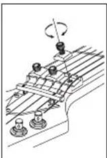
natural_image
Mechanical assembly diagram showing rotating components on a conveyor belt (no text or labels)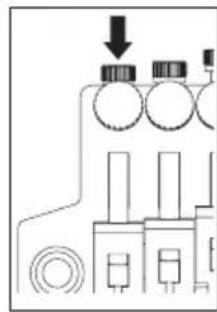
natural_image
Pure electrical circuit lines without any symbols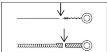
Mémo
natural_image
Mechanical assembly diagram showing a piston-cylinder joint inserted into a housing (no text or labels)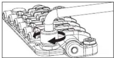
natural_image
Mechanical assembly diagram showing gear and shaft components with rotational arrows (no text or labels)RÉGLAGE DE L'ANGLE D'ATTAQUE DU VIBRATO
natural_image
Line drawing of a truck with roof and side-mounted equipment (no text or symbols)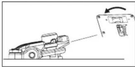
natural_image
Diagram of a mechanical device with an arrow indicating rotation or change, no text or symbols present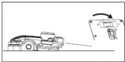
natural_image
Diagram showing a robotic arm interacting with a device, with an arrow indicating motion (no text or symbols present)natural_image
Technical diagram of a mechanical device with threaded components and mounting holes (no text or symbols)RÉGLAGE DE LA HAUTEUR DES CORDES
natural_image
Mechanical assembly diagram showing a rotating component with no visible text or symbolsRÉGLAGE DE L'INTONATION
natural_image
Mechanical assembly diagram showing a row of components with a rotating shaft and a pin (no text or labels)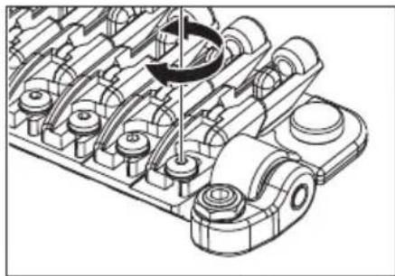
natural_image
Mechanical assembly diagram showing a gear mechanism with no visible text or symbols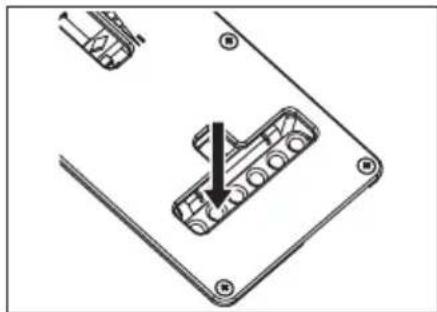
natural_image
Technical diagram showing a mechanical component with an arrow indicating assembly or insertion (no text or symbols present)INSTALLATION DE LA TIGE DU VIBRATO
natural_image
Pure electrical circuit lines without any symbols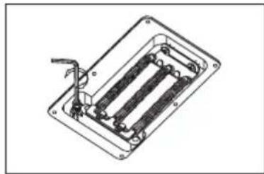
natural_image
Technical line drawing of a mechanical or electrical component with internal parallel slots and mounting brackets (no text or symbols)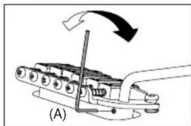
natural_image
Mechanical device with rotating arrow and labeled section (A), no readable text or symbols present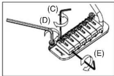
RÉGLAGE DE LA HAUTEUR DES CORDES (FAT20/FAT10/SAT10
RÉGLAGE DE L'INTONATION (FAT10/SAT10)
natural_image
Technical line drawing of a mechanical assembly with no visible text or symbolsRÉGLAGE DE L'INTONATION ET DE LA HAUTEUR DES CORDES (FAT 6/STD)
natural_image
Diagram of a mechanical device with rotating components and a tool, no text or symbols presentREMPLACEMENT DES CORDES
natural_image
Technical line drawing of a mechanical clamp or bracket assembly (no text or symbols)RÉGLAGE DU RESSORT DE VIBRATO
natural_image
Technical illustration of a mechanical assembly with springs and a tool (no text or symbols)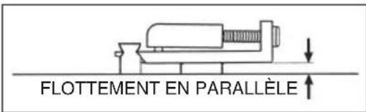
Mantenimiento
natural_image
Technical line drawing of two mechanical components with threaded ends and a central hub (no text or symbols)Nota
natural_image
Line drawing of a hand playing guitar chord with fretboard (no text or symbols)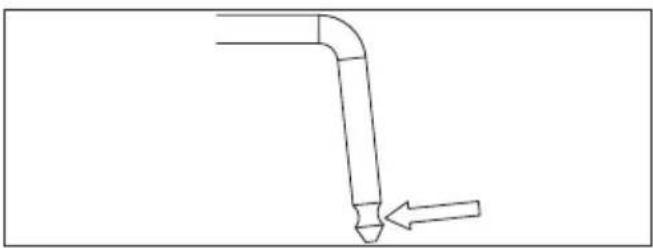
natural_image
Simple line drawing of a bent pipe with an arrow pointing to it (no text or symbols)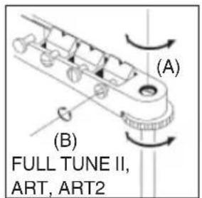
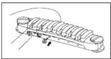
natural_image
Technical line drawing of a mechanical component with no visible text or symbolsnatural_image
Diagram showing a screwdriver interacting with a mechanical component, no text or symbols presentPUENTE GIBRALTAR ESTÁNDAR (MODELOS DE 7/8 CUERDAS)
PUENTE ARCH TOP AJUSTABLE
natural_image
Technical diagram of a mechanical component with rotating shaft and housing (no text or symbols)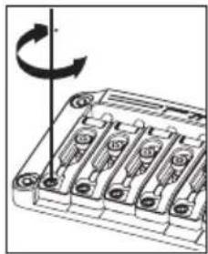
natural_image
Diagram of a battery pack with six slots and a rotating arrow indicating rotation (no text or symbols)natural_image
Technical diagram of a mechanical assembly with rotating components (no text or symbols)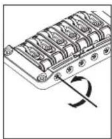
natural_image
Diagram of a mechanical component with a curved arrow indicating rotation (no text or symbols)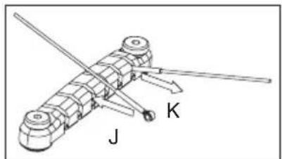
Locking Bridge
PUENTE FX EDGE III/FX EDGE III-8
natural_image
Technical line drawing of an internal combustion engine cylinder (no text or labels)natural_image
Technical line drawing of mechanical components, showing assembly and assembly details (no text or symbols)natural_image
Technical line drawing of an internal combustion engine cylinder (no text or labels)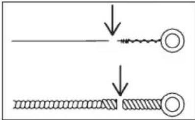
natural_image
Diagram showing two mechanical or electrical components with downward arrows indicating motion or force (no text or symbols)Nota
natural_image
Technical line drawing of a mechanical component with multiple cylindrical parts and a rotation arrow (no text or symbols)Locking Trémolos
Lo-Pro Edge
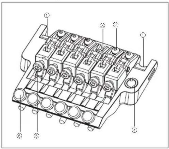
Parte trasera
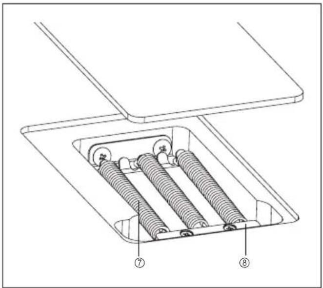
natural_image
Technical line drawing of a mechanical assembly with springs and housing (no text or symbols)natural_image
Technical line drawing of a mechanical component with no visible text or symbols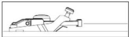
natural_image
Line drawing of a mechanical device with a lever and base (no text or symbols)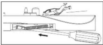
natural_image
Diagram showing a person climbing over a ramp with a tool inserted, illustrating the process (no text or symbols present)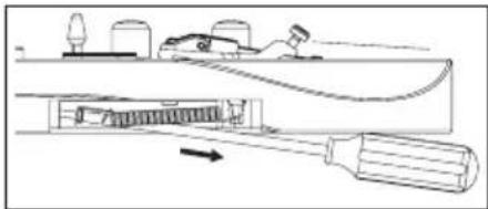
natural_image
Technical line drawing of a mechanical assembly with a tool and component, no visible text or symbolsnatural_image
Diagram of a mechanical assembly with a rotating tool and base plate (no text or symbols)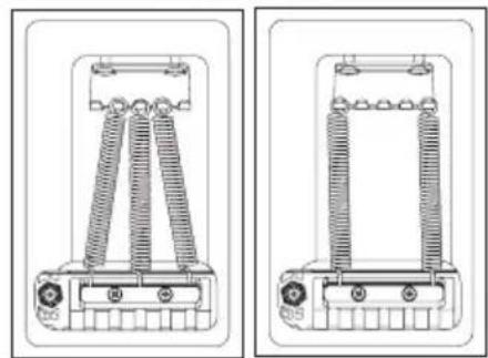
natural_image
Technical line drawing of two mechanical components with coiled springs and mounting brackets (no text or symbols)Nota
natural_image
Technical line drawing of a mechanical assembly with gears and shafts (no text or symbols)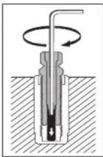
natural_image
Cross-sectional diagram of a mechanical component with rotating shaft and base, no text or symbols presentnatural_image
Technical line drawing of a mechanical component with multiple ports and mounting holes (no text or symbols)Nota
natural_image
Mechanical assembly diagram showing rotating components and fasteners (no text or labels)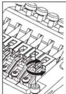
natural_image
Technical line drawing of a mechanical assembly with gears and shafts (no text or symbols)natural_image
Technical line drawing of a mechanical assembly with rotating components (no text or symbols)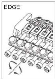
natural_image
Diagram of an engine block assembly with rotating components and a labeled edge (no text or symbols beyond label)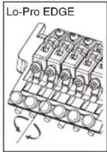
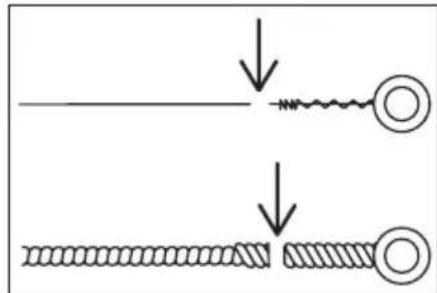
Nota
natural_image
Mechanical assembly diagram showing a pipe inserted into a component with multiple circular parts (no text or symbols visible)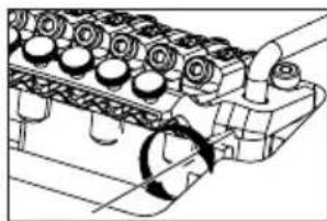
natural_image
Technical line drawing of an engine cylinder head assembly with no visible text or symbols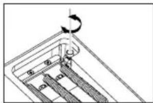
natural_image
Mechanical assembly diagram showing a rotating component with a curved arrow indicating rotation (no text or symbols)Nota
natural_image
Pure mechanical component diagram without any text, numbers, or symbols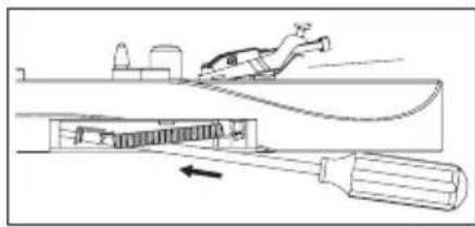
natural_image
Diagram of a mechanical device with a lever and gear, showing internal components and motion direction (no text or symbols)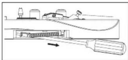
natural_image
Technical line drawing of a mechanical assembly with a tool and component (no text or symbols)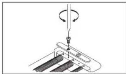
natural_image
Diagram of a mechanical assembly with a tool and rotating motion arrows (no text or symbols)
natural_image
Technical line drawing of a mechanical component with coiled spring and mounting base (no text or symbols)Nota
natural_image
Mechanical assembly diagram showing a rotating mechanism with no visible text or symbolsnatural_image
Technical line drawing of a mechanical assembly with rotating components (no text or symbols)natural_image
Technical line drawing of a mechanical assembly with multiple cylindrical components and mounting holes (no text or symbols)natural_image
Technical line drawing of a mechanical assembly with multiple cylindrical components and rotational arrows (no text or symbols)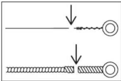
natural_image
Mechanical assembly diagram showing a rotating mechanism with no visible text or symbolsEdge-Zero Vista general
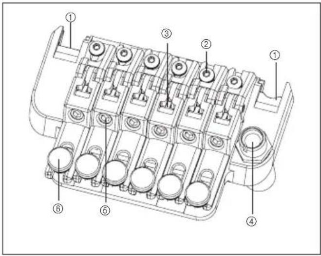
Parte trasera 2
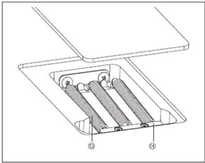
natural_image
Technical line drawings of mechanical components, one showing a pipe inserted into a housing and the other showing a valve assembly (no text or symbols present)AJUSTE DEL ÁNGULO DEL TRÉMOLO Y DEL SISTEMA ZERO POINT
- Modelos sin sistema Zero Point
natural_image
Pure mechanical component diagram without any text, numbers, or symbols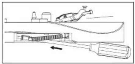
natural_image
Diagram of a mechanical device with a tool and component, showing internal structure and motion direction (no text or symbols)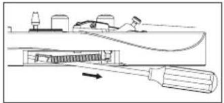
natural_image
Technical line drawing of a mechanical assembly with a tool and component, no visible text or symbols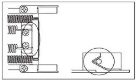
natural_image
Technical line drawing of mechanical components with spring and housing (no text or symbols)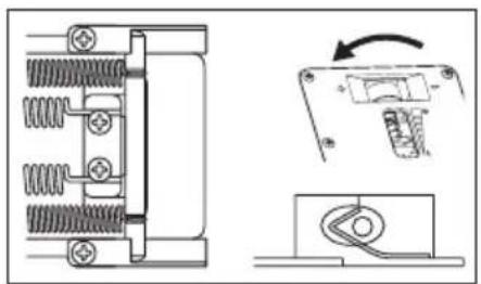
natural_image
Pure electrical circuit lines without any symbols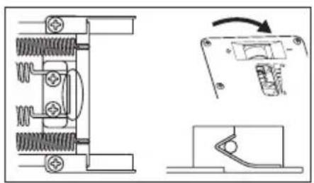
natural_image
Technical line drawing of a mechanical assembly with spring-loaded components and a close-up view of a switch mechanism (no text or symbols)
natural_image
Diagram of a mechanical assembly with a tool and rotating motion arrows (no text or symbols)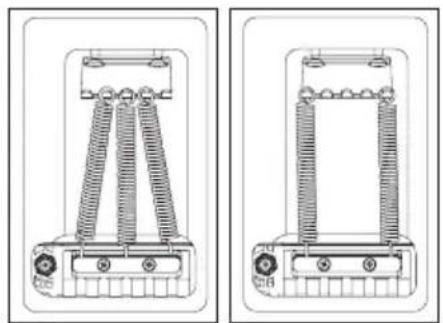
natural_image
Technical line drawing of two mechanical components with spring-like elements and mounting holes (no text or symbols)Nota
natural_image
Technical diagram of an internal mechanical assembly with springs and tubing (no text or labels)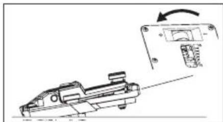
natural_image
Technical line drawing of a mechanical component with an arrow indicating rotation (no text or symbols present)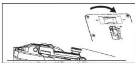
natural_image
Technical line drawing of a mechanical component with an arrow indicating rotation (no text or symbols)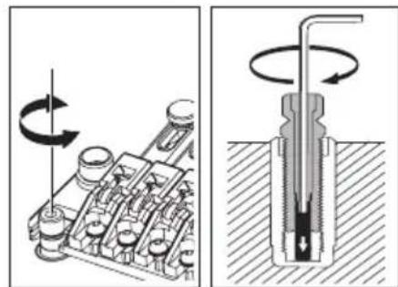
natural_image
Mechanical assembly diagram showing a rotating component and a cross-sectional view of a mechanical component (no text or symbols)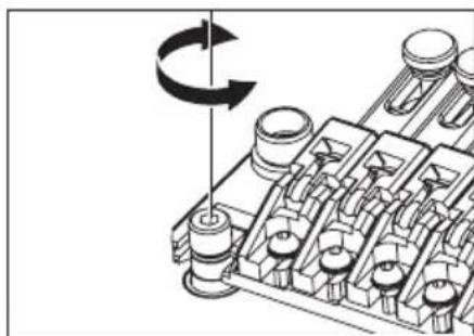
natural_image
Mechanical assembly diagram showing a rotating component with no visible text or symbolsNota
natural_image
Technical line drawing of a mechanical assembly with no visible text or symbols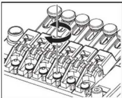
natural_image
Technical illustration of a mechanical assembly with multiple components and a central rotating element (no text or symbols)natural_image
Technical line drawing of a mechanical component with multiple cylindrical cavities and mounting holes (no text or symbols)
natural_image
Diagram showing two stages of a coiled wire or filament, with arrows indicating process direction (no text or symbols)Nota
natural_image
Technical line drawing of a mechanical component with multiple cylindrical cavities and mounting holes (no text or symbols)Vista general
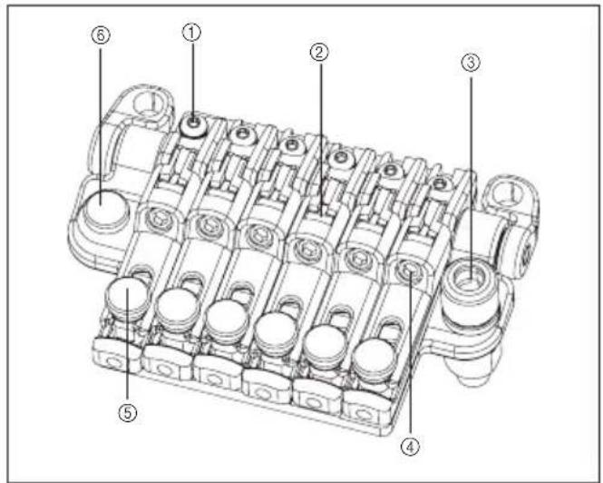
⑦ Muelle principal
⑧ Muelle secundario
⑨ Tope
⑩ Varilla de tope
⑪ Bloque del trémolo
⑫ Manilla de ajuste del muelle
natural_image
Mechanical assembly diagram showing a piston-cranked engine cylinder with pipe connection (no text or labels)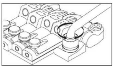
natural_image
Technical line drawing of a mechanical assembly with no visible text or symbolsAJUSTE DEL ÁNGULO DEL TRÉMOLO Y DEL SISTEMA ZERO POINT
natural_image
Technical line drawing of a mechanical assembly with spring and housing components (no text or symbols)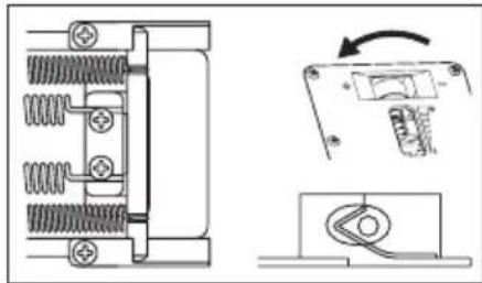
natural_image
Pure electrical circuit lines without any symbols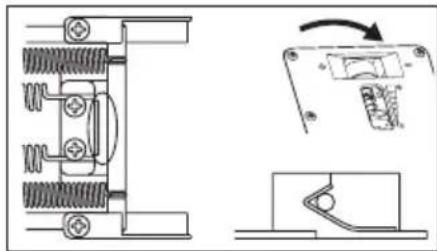
natural_image
Technical line drawing of a mechanical assembly with spring-loaded components and a separate view showing a switch mechanism (no text or symbols)natural_image
Technical diagram of a mechanical assembly with springs and housing (no text or labels)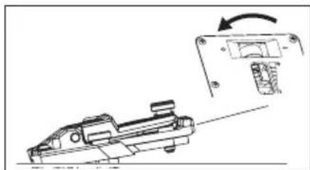
natural_image
Technical line drawing of a mechanical component with an arrow indicating rotation (no text or symbols present)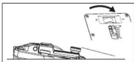
natural_image
Technical line drawing of a mechanical component with an arrow indicating motion (no text or symbols)natural_image
Mechanical assembly diagram showing a rotating component with no visible text or symbols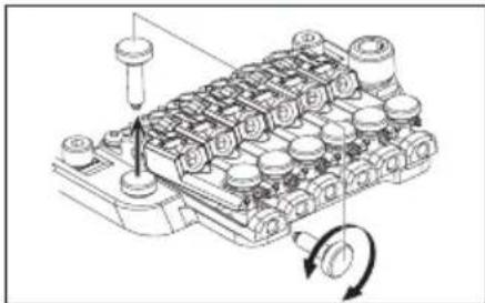
natural_image
Technical line drawing of a mechanical component with no visible text or symbols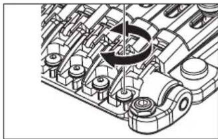
natural_image
Technical line drawing of a mechanical assembly with gears and shafts (no text or symbols)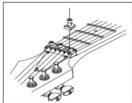
natural_image
Technical line drawing of a guitar fretboard with no visible text or symbols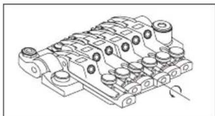
natural_image
Technical line drawing of a mechanical component with multiple cylindrical ports and mounting holes (no text or symbols)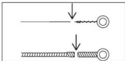
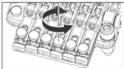
natural_image
Mechanical assembly diagram showing piston and crankshaft components (no text or labels)Vista general
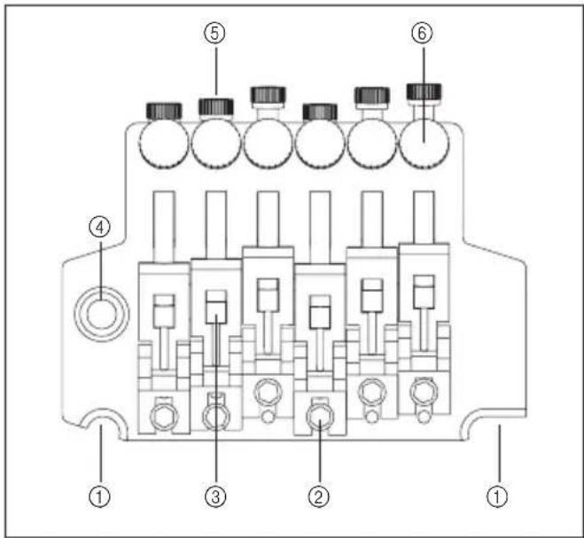
natural_image
Pure technical line drawing of a mechanical component without any text, numbers, or symbols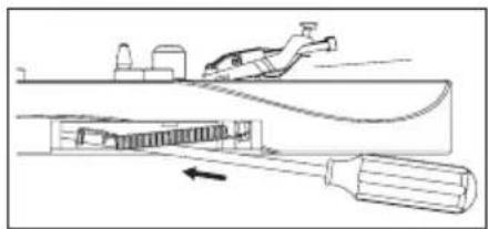
natural_image
Diagram of a mechanical device with a tool inserted into a housing, showing internal components and motion direction (no text or symbols)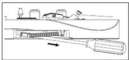
natural_image
Technical line drawing of a mechanical assembly with a tool and component, no visible text or symbolsnatural_image
Mechanical assembly diagram showing rotating components on a curved surface (no text or symbols)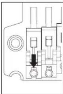
natural_image
Pure electrical circuit lines without any symbolsnatural_image
Technical line drawing of a mechanical assembly with rotating components (no text or symbols)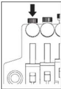
natural_image
Pure electrical circuit lines without any symbols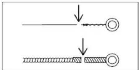
Nota
④Muelle del trémolo
⑤Tope del bloque del trémolo
⑥Boton tope del bloque del trémolo
⑦Bloque del trémolo
⑧Manilla de ajuste del muelle
natural_image
Mechanical assembly diagram showing a pipe inserted into a cylindrical component (no text or symbols)natural_image
Mechanical assembly diagram showing gear and shaft components with directional arrows (no text or labels)natural_image
Line drawing of a truck with no visible text, numbers, or symbols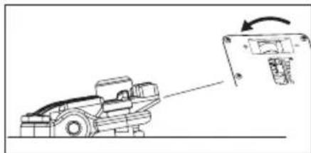
natural_image
Diagram of a vehicle with an arrow indicating motion or change, showing a vehicle on the ground (no text or symbols present)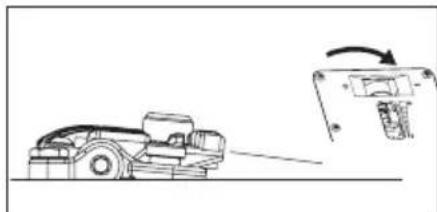
natural_image
Diagram showing a vehicle on a road with an arrow indicating motion, next to a mechanical component (no text or symbols present)Tope de palanca arriba
natural_image
Technical diagram of a mechanical assembly with threaded components and a directional arrow (no text or symbols)natural_image
Mechanical assembly diagram showing a rotating shaft and housing components (no text or labels)Octavación
natural_image
Mechanical assembly diagram showing a motor with rotating wheels and a pin inserted (no text or labels)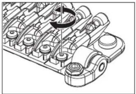
natural_image
Technical illustration of a mechanical assembly with gears and shafts (no text or symbols)Cambio de cuerdas
natural_image
Mechanical assembly diagram showing a component inserted into a housing (no text or symbols visible)natural_image
Pure electrical circuit lines without any symbols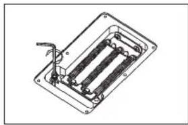
natural_image
Technical line drawing of a mechanical or electrical component with internal parallel slots and a handle (no text or symbols)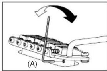
natural_image
Mechanical assembly diagram showing a lever mechanism with motion arrows (no text or symbols)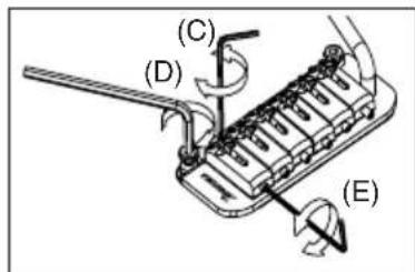
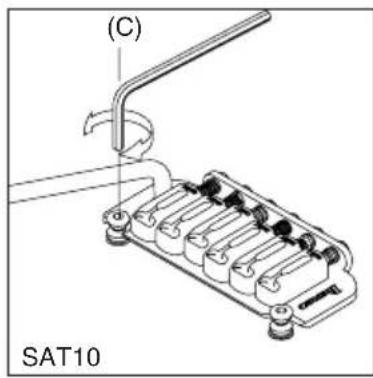
natural_image
Technical line drawing of a mechanical component with no visible text or symbolsnatural_image
Diagram of a mechanical device with rotating components and directional arrows indicating motion (no text or symbols)natural_image
Technical line drawing of a mechanical clamp or bracket assembly (no text or symbols)FAT/SAT (EXCEPTO FAT6) AJUSTE DE LOS MUELLES DEL TRÉMOLÓ
natural_image
Technical illustration of a mechanical clamp or spring assembly (no text or symbols visible)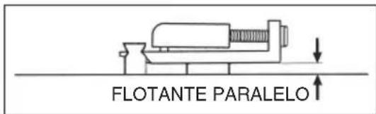
Manutenzione
ACCESSORI INCLUSI
| Strumento multiuso | Leva tremolo | Chiave a brugola | Chiave a esagono incassato da 8 mm | |||||
| 1,5mm | 2mm 2,5 | mm 3mm | 4mm | |||||
| Serie PREMIUM ponte tremolo Edge | ○ | ○ | ||||||
| Serie PREMIUM Edge-Zero II con ZPS | ○ | ○ | ||||||
| Serie PREMIUM ponte tremolo ZR con ZPS2 | ○ | ○ | ||||||
| Serie PREMIUM ponte Tight-End R | ○ | |||||||
| Ponte tremolo Edge III | ○ | ○ | ○ | ○ | ○ | |||
| Edge-Zero II con ZPS | ○ | ○ | ○ | ○ | ||||
| Edge-Zero II senza ZPS | ○ | ○ | ○ | ○ | ||||
| Ponte tremolo FAT6 | ○ | ○ | ○ | ○ | ||||
| Ponte tremolo FAT10 | ○ | ○ | ○ | ○ | ||||
| Ponte FX Edge III | ○ | ○ | ○ | |||||
| Ponte FX Edge III -8 | ○ | ○ | ○ | |||||
| Ponte Gibraltar Standard 6/7/8 | ○ | ○ | ○ | |||||
| Ponte tremolo SAT10 | ○ | ○ | ○ | ○ | ||||
| Ponte tremolo SAT-Pro II | ○ | ○ | ○ | ○ | ||||
| Ponte tremolo STD | ○ | |||||||
| Ponte tremolo STD-DL | ○ | |||||||
| Ponte Tight-End | ○ | ○ | ||||||
| Ponte Tight-Tune | ○ | ○ | ||||||
| Ponte tremolo ZR con ZPS2 | ○ | ○ | ○ | ○ | ||||
| Ponte tremolo SynchroniZR | ○ | ○ | ||||||
| PONTE GIBRALTAR 08 / CORDIERA QUICK CHANGE 08 | ○ | |||||||
natural_image
Technical line drawing of two mechanical fasteners with hexagonal bases and threaded ends (no text or symbols)natural_image
Pure diagram of a mechanical or fluid system with no text, numbers, or symbolsnatural_image
Line drawing of a hand playing guitar with fretboard and strings (no text or symbols)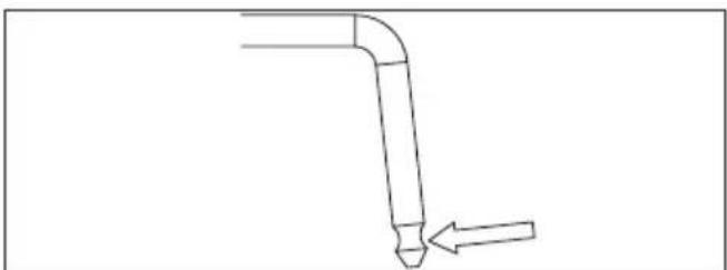
natural_image
Simple line drawing of a bent pipe with an arrow indicating direction (no text or symbols)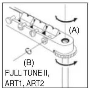

natural_image
Technical line drawing of a mechanical component with multiple grooves and mounting holes (no text or symbols)SOSTITUZIONE DELLE CORDE: CB3
natural_image
Diagram of a screwdriver working on an electronic component with rotating arrows indicating rotation (no text or symbols present)PONTE GIBRALTAR STANDARD (MODELLI A 7 E 8 CORDE)
natural_image
Technical line drawing of a mechanical component with labeled dimensions A and B (no text or symbols beyond labels)Vibrato Vintage
natural_image
Technical diagram of a mechanical component with rotational arrow indicating motion (no text or symbols)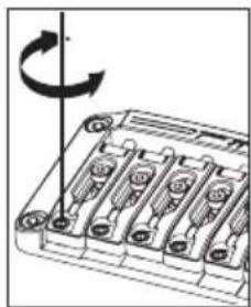
natural_image
Diagram of a battery pack with six slots and a rotating arrow indicating rotation (no text or symbols)natural_image
Technical diagram of a mechanical component with a rotating arrow indicating rotation (no text or symbols present)
natural_image
Diagram of a mechanical component with multiple slots and a curved arrow indicating rotation (no text or symbols)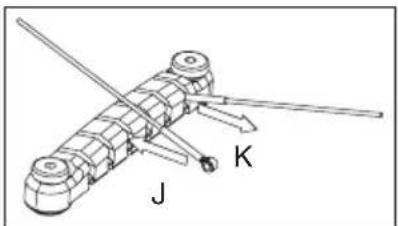
natural_image
Mechanical device with labeled components J and K, no readable text or symbols beyond labelsLocking Bridge
PONTE FX EDGE III/FX EDGE III-8
FX Edge III
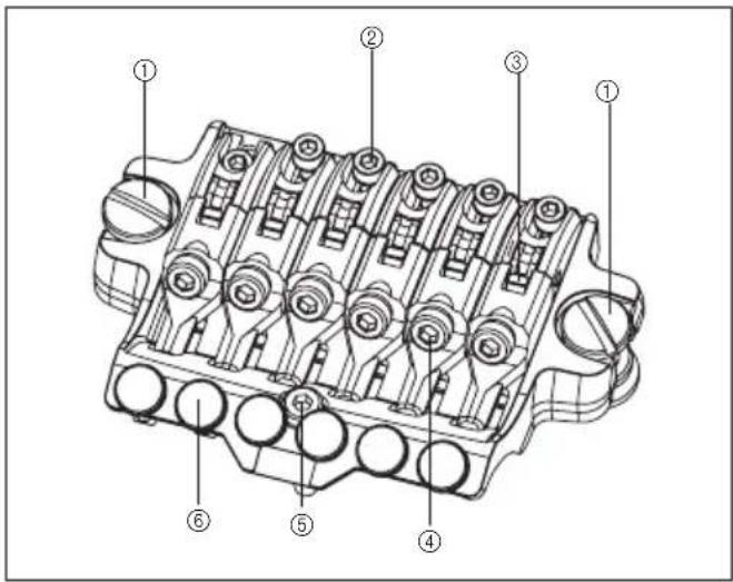
natural_image
Technical diagram of an internal combustion engine cylinder with no visible text or symbolsnatural_image
Pure electrical circuit lines without any symbols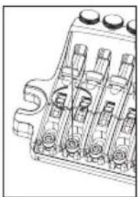
natural_image
Technical line drawing of a mechanical component with multiple cylindrical parts and mounting holes (no text or symbols)natural_image
Technical line drawing of an internal combustion engine cylinder (no text or labels)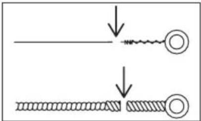
Nota
natural_image
Technical line drawing of a mechanical component with multiple cylindrical parts and a central knob (no text or symbols)Locking Tremolos
PONTE TREMOLO EDGE
Edge
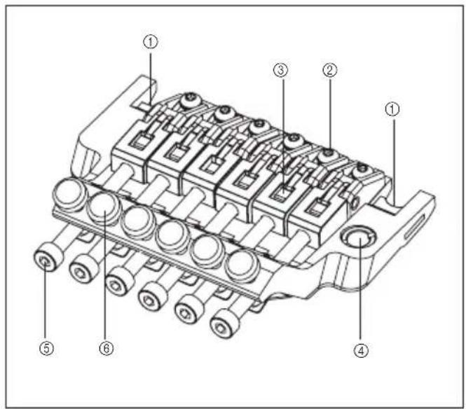
Lo-Pro Edge
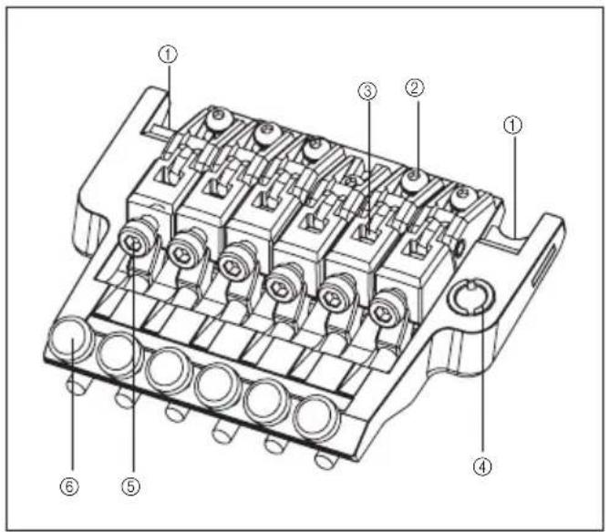
Retro
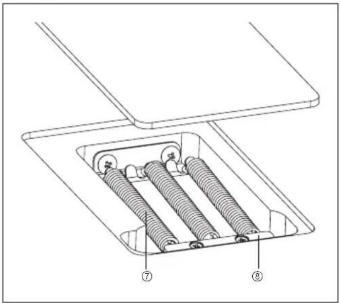
natural_image
Technical line drawing of a mechanical assembly with springs and housing (no text or symbols)natural_image
Technical line drawing of a mechanical component with no visible text or symbols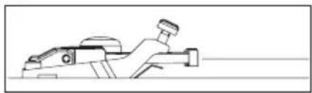
natural_image
Line drawing of a mechanical device with no visible text or symbols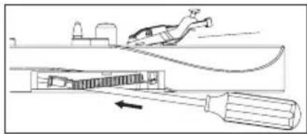
natural_image
Technical line drawing of a mechanical assembly with a tool and component, no visible text or symbols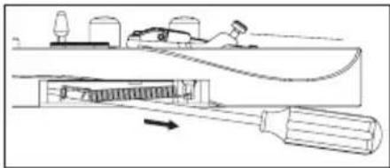
natural_image
Technical line drawing of a mechanical assembly with a tool inserted, showing internal components and motion direction (no text or symbols)MOLLE DEL TREMOLO
natural_image
Diagram of a mechanical assembly with a rotating component and a base plate (no text or symbols)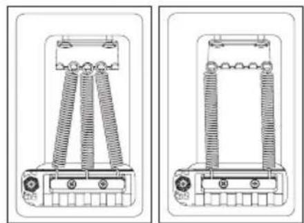
natural_image
Technical line drawings of two electrical components with coiled springs and terminals (no text or symbols)Nota
natural_image
Technical line drawing of a mechanical assembly with no visible text or symbols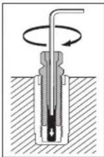
natural_image
Cross-sectional diagram of a mechanical component with rotational motion indicated by arrows (no text or labels)natural_image
Technical line drawing of a mechanical component with multiple slots and mounting holes (no text or symbols)Nota
natural_image
Mechanical assembly diagram showing rotating components and connecting rods (no text or labels)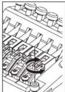
natural_image
Technical line drawing of a mechanical assembly with gears and shafts (no text or symbols)natural_image
Technical line drawing of a mechanical assembly with rotating components (no text or symbols)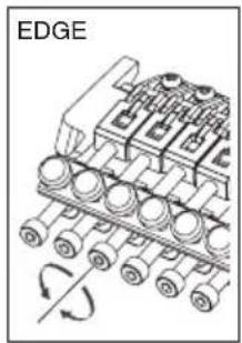
natural_image
Diagram of an electronic component with multiple pins and a rotating arrow, labeled 'EDGE' (no text or symbols on the diagram itself)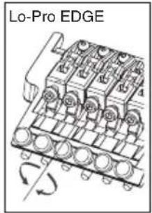
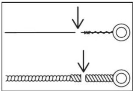
Nota
natural_image
Mechanical assembly diagram showing a pipe inserted into a component with bolt holes (no text or labels)
natural_image
Technical line drawing of an engine cylinder head with internal components and a curved arrow indicating rotation (no text or symbols)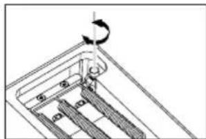
natural_image
Mechanical assembly diagram showing a rotating component with a curved arrow indicating motion (no text or symbols)Nota
natural_image
Diagram of a mechanical assembly with a rotating shaft and base plate (no text or symbols)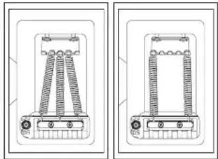
natural_image
Technical line drawing of a mechanical device with coiled spring components (no text or symbols)Nota
natural_image
Mechanical assembly diagram showing gear and shaft components with rotational motion indicator (no text or symbols)natural_image
Technical line drawing of a mechanical assembly with rotating components and mounting base (no text or symbols)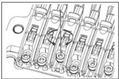
natural_image
Technical line drawing of internal combustion engine components (no text or labels)natural_image
Technical line drawing of a mechanical component with multiple circular components and rotational arrows (no text or symbols)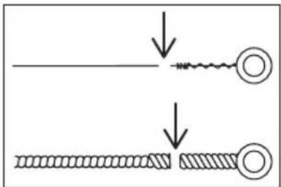
natural_image
Mechanical assembly diagram showing a rotating component with multiple circular components (no text or symbols)Panoramica
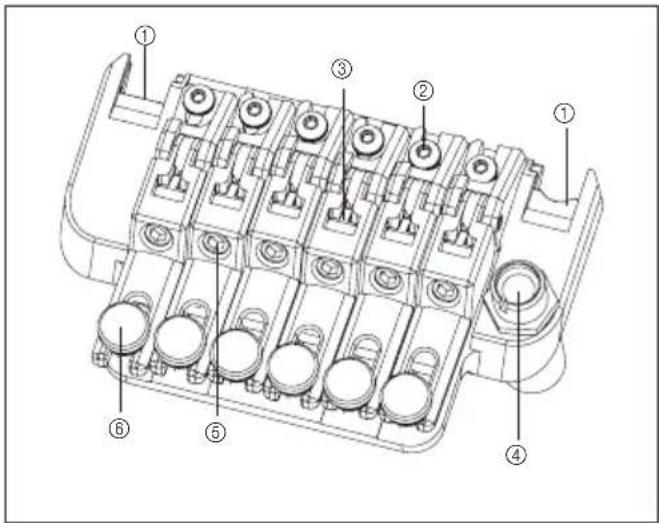
Retro 2
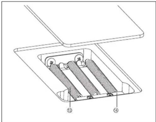
MONTAGGIO DELLA LEVA TREMOLO
natural_image
Technical illustration of a mechanical assembly with pipe and housing components (no text or symbols)natural_image
Pure mechanical component diagram without any text, numbers, or symbols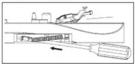
natural_image
Line drawing of a mechanical device with a tool inserted, showing internal components and motion direction (no text or symbols)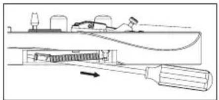
natural_image
Technical line drawing of a mechanical assembly with a tool and spring component (no text or symbols)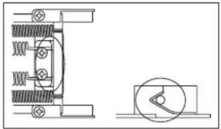
natural_image
Technical line drawing of a mechanical assembly with spring and housing components (no text or symbols)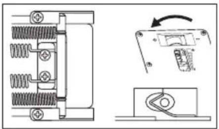
natural_image
Technical diagram showing spring-loaded components and a right-hand panel with an arrow indicating rotation (no text or symbols)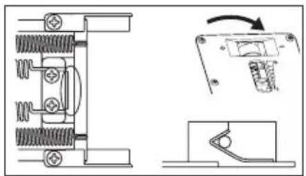
natural_image
Technical line drawing of a mechanical assembly with spring-loaded components and a close-up view of a switch mechanism (no text or symbols)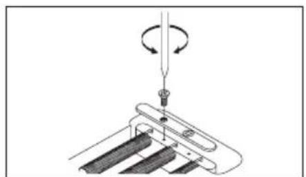
natural_image
Diagram of a mechanical assembly with a rotating component and a base plate (no text or symbols)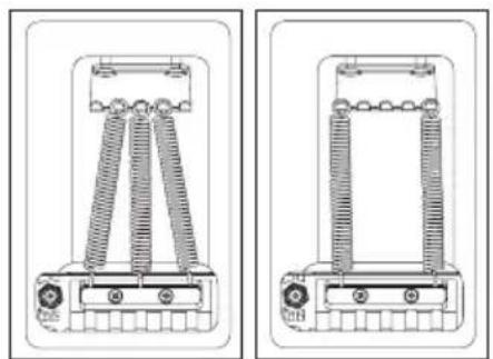
natural_image
Technical line drawings of two mechanical components with spring-like elements and mounting base (no text or symbols)Nota
natural_image
Mechanical assembly diagram showing internal components with springs and tubing (no text or labels)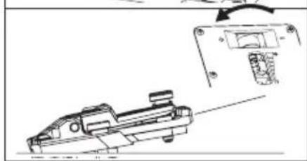
natural_image
Technical line drawing of a mechanical component with an inset showing a close-up view (no text or symbols)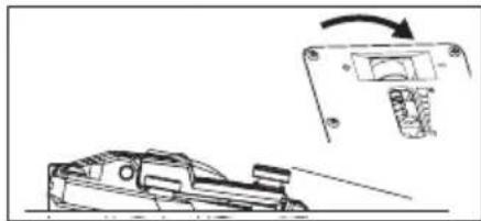
natural_image
Technical line drawing of a mechanical component with an inset showing a close-up view of a component (no text or symbols present)
natural_image
Technical illustration showing mechanical assembly and internal component alignment (no text or symbols)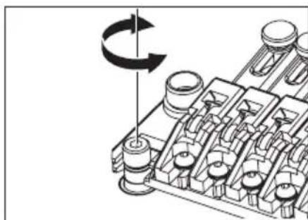
natural_image
Mechanical assembly diagram showing a rotating component with a curved arrow indicating rotation (no text or symbols present)Nota
natural_image
Technical line drawing of a mechanical assembly with no visible text or symbols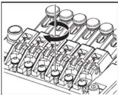
natural_image
Mechanical assembly diagram showing piston and crankshaft components (no text or labels)natural_image
Technical line drawing of a mechanical assembly with pipes and components (no text or symbols)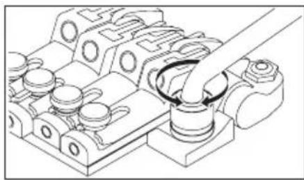
natural_image
Technical line drawing of a mechanical assembly with no visible text or symbolsnatural_image
Technical line drawing of a mechanical assembly with spring and housing components (no text or symbols)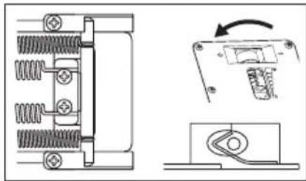
natural_image
Technical line drawing of a mechanical component with spring and housing, showing assembly steps (no text or symbols)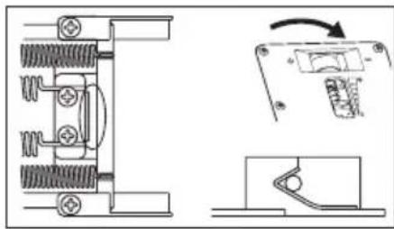
natural_image
Technical line drawing of a mechanical component with spring and housing, showing assembly and disassembly views (no text or symbols)DISABILITAZIONE DEL SISTEMA ZERO POINT (UTILIZZO DELL'UNITÀ COME TREMOLO FL OTTANTE TRADIZIONALE)
natural_image
Technical diagram of a mechanical assembly with springs and housing (no text or labels)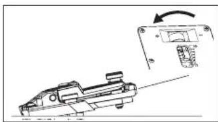
natural_image
Technical line drawing of a mechanical component with an arrow indicating rotation (no text or symbols)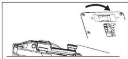
natural_image
Technical line drawing of a mechanical component with an inset showing a close-up of a component (no text or symbols)natural_image
Mechanical assembly diagram showing a rotating component with no visible text or symbols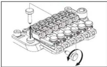
natural_image
Technical diagram of a mechanical assembly with no visible text or symbols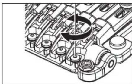
natural_image
Technical illustration of an engine cylinder assembly (no text or symbols visible)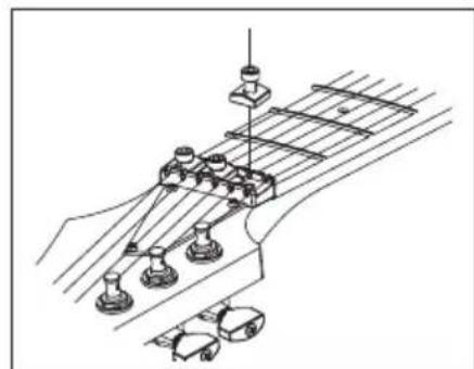
natural_image
Technical line drawing of a mechanical assembly with no visible text or symbols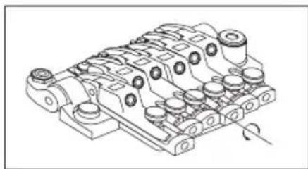
natural_image
Technical line drawing of a mechanical component with multiple cylindrical parts and mounting holes (no text or symbols)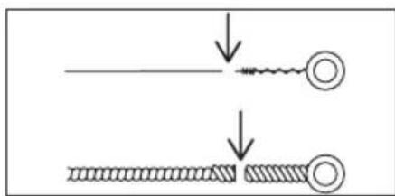
natural_image
Diagram showing two stages of a wire or filament process with arrows indicating direction (no text or symbols)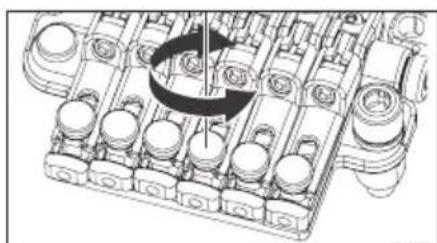
natural_image
Mechanical assembly diagram showing a rotating component with no visible text or symbolsPanoramica
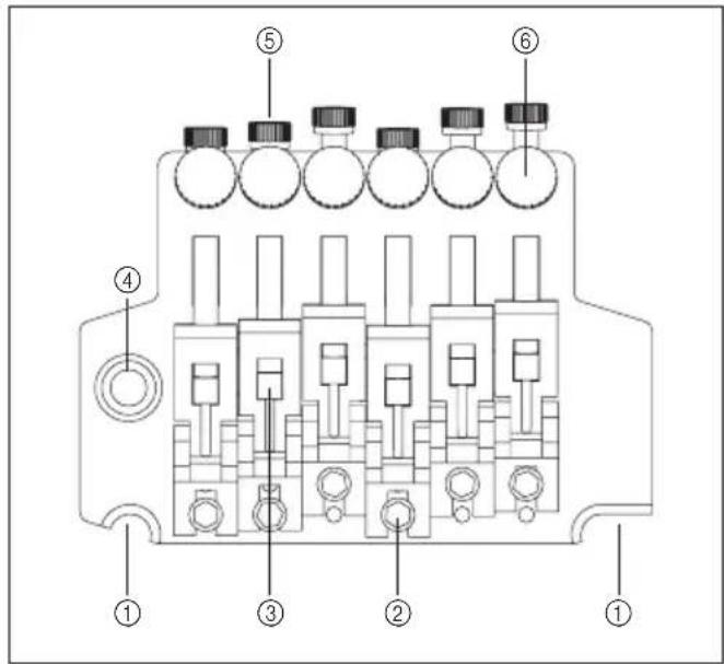
natural_image
Pure technical line drawing of a mechanical component without any text, numbers, or symbols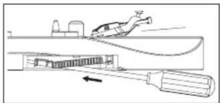
natural_image
Diagram of a mechanical device with a lever and tool, showing internal components and motion direction (no text or symbols)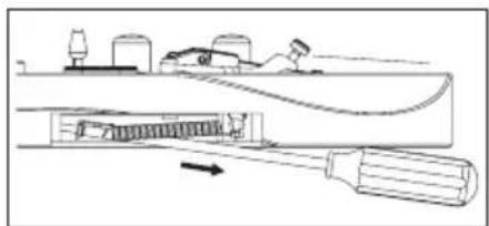
natural_image
Technical line drawing of a mechanical assembly with a tool and component, no visible text or symbolsnatural_image
Mechanical assembly diagram showing rotating components on a conveyor belt (no text or labels)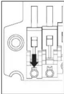
natural_image
Pure mechanical component diagram without any text, numbers, or symbols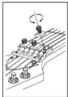
natural_image
Mechanical assembly diagram showing rotating components on a conveyor belt (no text or labels)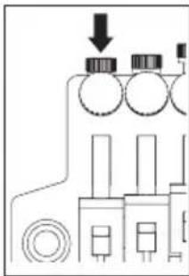
natural_image
Pure electrical circuit lines without any symbols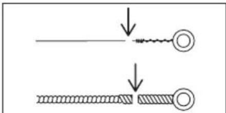
Nota
natural_image
Technical line drawing of a mechanical assembly with a pipe inserted into a housing (no text or symbols)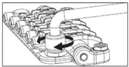
natural_image
Mechanical assembly diagram showing a multi-stage gear mechanism with rotating shaft and housing (no text or labels)natural_image
Line drawing of a truck with roof and side-mounted equipment (no text or symbols)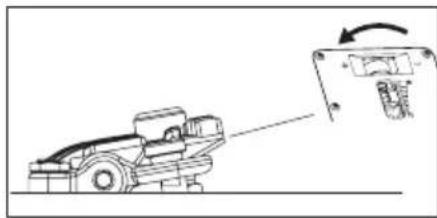
natural_image
Diagram of a vehicle with a sensor or sensor device interacting with a mechanical component (no text or symbols present)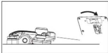
natural_image
Line drawing of a truck with an arrow indicating motion, next to a mechanical component (no text or symbols)ARRESTO ARM-UP
natural_image
Mechanical assembly diagram showing a clamping device with threaded components and directional arrows indicating motion (no text or symbols)REGOLAZIONE DELL'ALTEZZA DELLE CORDE
natural_image
Mechanical assembly diagram showing a rotating component with no visible text or symbolsnatural_image
Mechanical assembly diagram showing a conveyor belt system with rotating wheel and pulley (no text or labels)natural_image
Technical line drawing of a mechanical assembly with gears and housing (no text or symbols)natural_image
Mechanical assembly diagram showing a vehicle component inserted into a housing (no text or symbols visible)MONTAGGIO DEL BRACCIO DEL TREMOLO
natural_image
Pure mechanical diagram of a lever handle connecting two blocks (no text or symbols)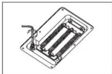
natural_image
Technical line drawing of a mechanical or electrical component with internal parallel plates and a handle (no text or symbols)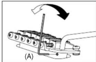
natural_image
Mechanical assembly diagram showing a lever mechanism with motion arrows (no text or symbols)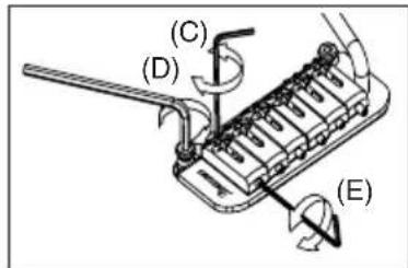
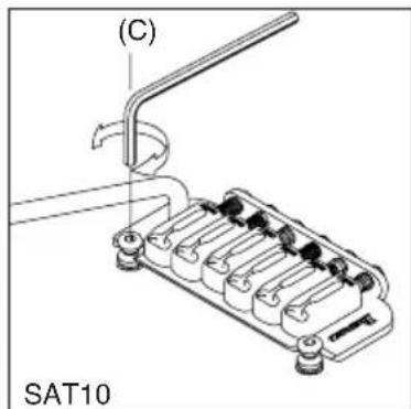
natural_image
Technical line drawing of a mechanical assembly with no visible text or symbols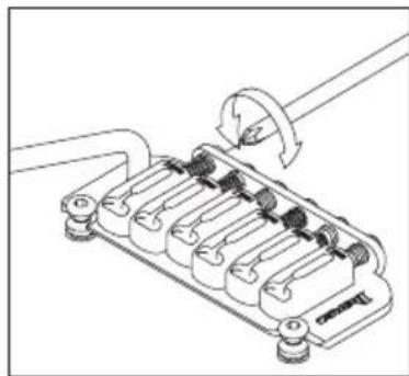
natural_image
Technical line drawing of a mechanical component with no visible text or symbolsnatural_image
Diagram of a mechanical device with rotating components and directional arrows (no text or symbols)natural_image
Mechanical assembly diagram showing spring and rod components (no text or labels)FAT/SAT (TRANNE FAT6) REGOLAZIONE DELLA MOLLA DEL TREMOLO
natural_image
Technical illustration of a mechanical assembly with threaded components and a tool (no text or symbols)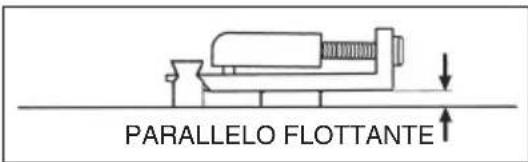
维护保养
配件
| 1st 2nd | 3rd 4th 5th | 6th 7th 8th | ||||||
| 六弦 | E4 B3 | G3 D3 A2 E2 | -- | |||||
| 七弦 | E4 B3 | G3 D3 A2 E2 | B1 - | |||||
| 八弦 | D#4 A#3 | F#3 C#3 G | #2 D#2 D#2 | F1 |
注意下列型号的设置方式不同
Baritone guitar
| 1st 2nd | 3rd 4th 5th 6th | 7th 8th | |||||
| B | F# | D | A | E | B | - | - |
RGD. APEX
| 1st 2nd 3rd 4th 5th 6th 7th | |||||||
| 六弦 | D4 | A3 | F3 | C3 | G2 | D2 | - |
| 七弦 | D4 | A3 | F3 | C3 | G2 | D2 | A1 |
MTM100
| 1st 2nd | 3rd 4th 5th 6th | 7th 8th | |||||
| C# | G# | E | B | F# | B | - | - |
TAM10
| 1st 2nd | 3rd 4th 5th 6th | 7th 8th | |||||
| E | B | G | D | A | E | B | E |
natural_image
Technical line drawing of two mechanical components with threaded ends and flanges (no text or symbols)注
- 必须小心调整琴颈。
natural_image
Line drawing of a hand playing guitar with fretboard and strings (no text or symbols)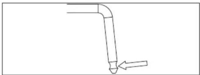
natural_image
Simple line drawing of a bent pipe with a pointed tip and an arrow indicating direction (no text or symbols)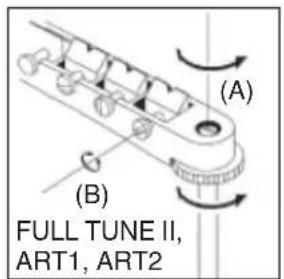
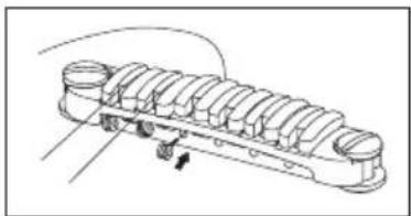
natural_image
Technical line drawing of a multi-layered mechanical component with no visible text or symbols更换琴弦: CB3
安装琴弦时,请从琴桥的前面插入琴弦。
natural_image
Diagram showing screwdriver working on a mechanical component with rotating arrows indicating motion (no text or symbols)GIBRALTER STANDARD 琴桥 (7-弦/8-弦型号)
可调拱形面板琴桥
端
natural_image
Technical line drawing of a mechanical component with labeled dimensions A and B (no text or symbols beyond labels)获得醇厚的颤音
natural_image
Technical diagram of a mechanical component with rotational arrow indicating motion (no text or symbols)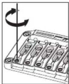
natural_image
Diagram of a battery pack with six slots and an arrow indicating rotational direction (no text or symbols)调整八音
natural_image
Technical diagram of a mechanical component with rotational arrow indicating motion (no text or symbols)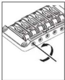
natural_image
Diagram of a mechanical component with a curved arrow indicating rotation (no text or symbols)换弦
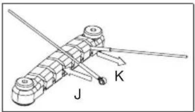
natural_image
Mechanical device with labeled parts J and K, no readable text or symbols beyond labels固定琴桥
FX EDGE III/FX EDGE III-8 琴桥
FX Edge III
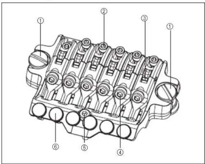
natural_image
Technical diagram of an internal combustion engine cylinder with no visible text or labels调整八音
natural_image
Technical line drawing of a mechanical assembly with no visible text or symbols更换琴弦
natural_image
Technical line drawing of a mechanical component with internal gears and shafts (no text or symbols)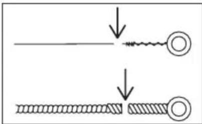
注
natural_image
Technical line drawing of a mechanical component with multiple cylindrical parts and a rotation arrow (no text or symbols)弦锁摇把
EDGE 颤音琴桥
Edge
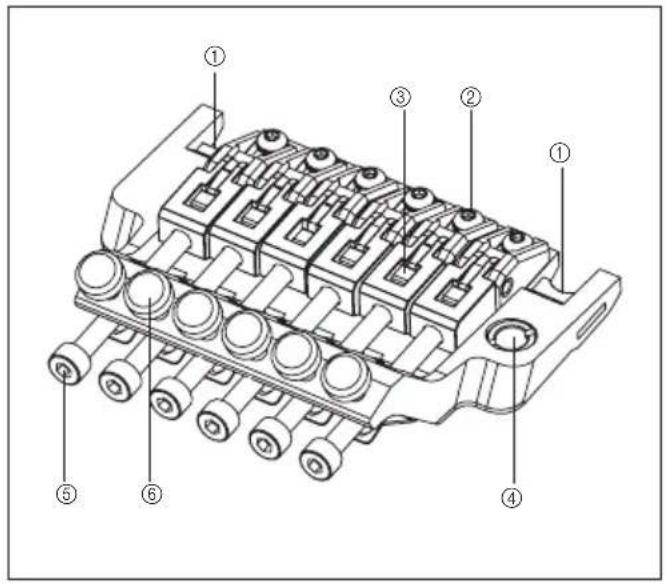
Lo-Pro Edge
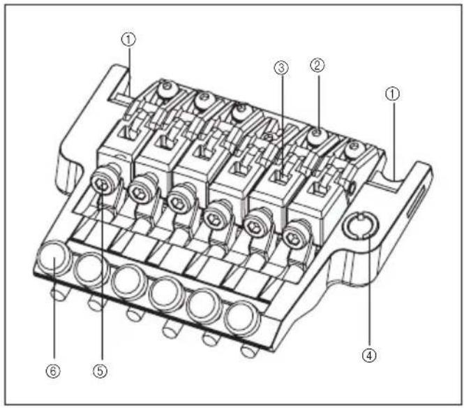
后
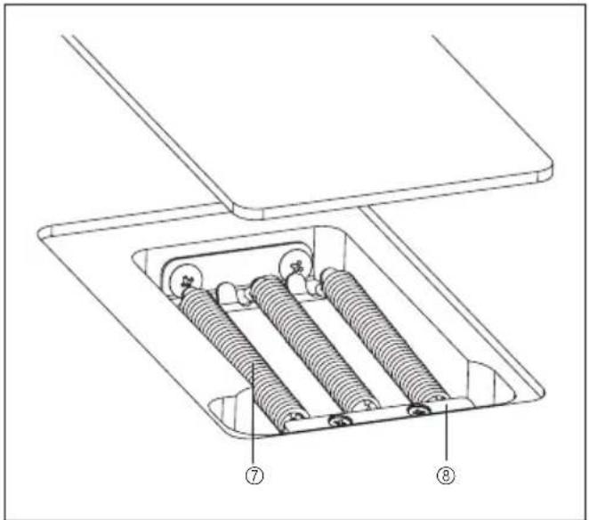
① 刀口
② 琴码锁定螺栓
③ 琴弦固定块
④颤音臂插孔
⑤ 琴弦止动螺栓
⑥ 微调螺栓
⑦颤音器弹簧
⑧ 弹簧锁
安装摇把
natural_image
Technical line drawing of a mechanical assembly with springs and housing (no text or symbols)natural_image
Technical line drawing of a mechanical component with no visible text or symbols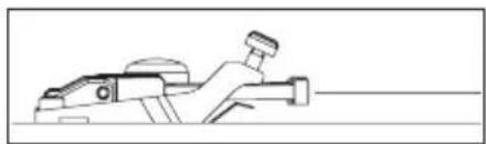
natural_image
Line drawing of a mechanical component or tool, possibly a cutting or assembly, with no visible text or symbols.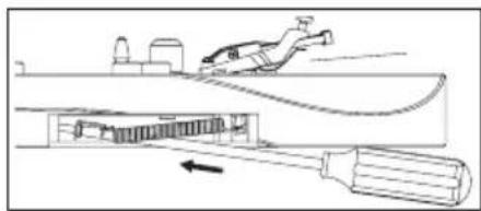
natural_image
Diagram of a mechanical device with a lever and cable, showing internal components and motion direction (no text or symbols)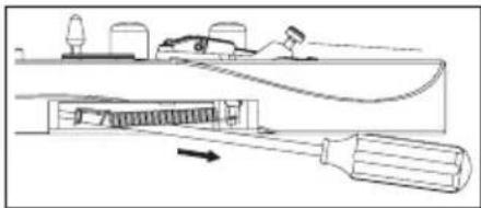
natural_image
Technical line drawing of a mechanical assembly with a tool inserted into a component (no text or symbols)颤音器弹簧
natural_image
Diagram of a mechanical assembly with a rotating component and base plates (no text or symbols)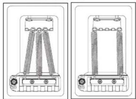
natural_image
Technical line drawings of two mechanical components with coiled springs and mounting holes (no text or symbols)注
natural_image
Technical line drawing of a mechanical assembly with no visible text or symbols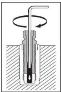
natural_image
Cross-sectional diagram of a mechanical component with rotational motion arrows (no text or labels)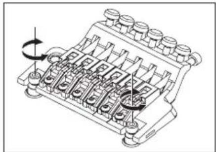
natural_image
Technical line drawing of a mechanical component with multiple ports and rotating arrows (no text or symbols)注
调整弦高时确保松开螺栓锁定紧固螺丝。
调整八音
natural_image
Technical line drawing of a mechanical assembly with rotating components (no text or symbols)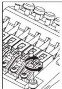
natural_image
Technical line drawing of a mechanical assembly with gears and shafts (no text or symbols)换弦
natural_image
Technical line drawing of a mechanical assembly with rotating components (no text or symbols)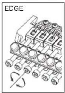
natural_image
Diagram of an industrial conveyor system with rotating components and a labeled edge (no text or symbols beyond label)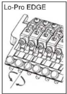
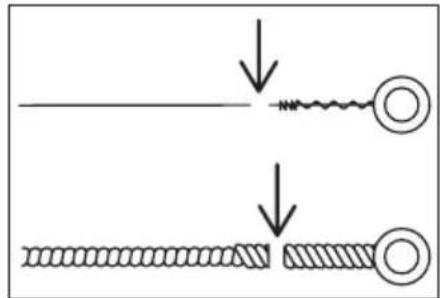
注
⑤ 琴弦止动螺栓
⑥ 微调螺栓
⑦颤音器弹簧
⑧ 弹簧锁
安装摇把
natural_image
Mechanical assembly diagram showing a pipe inserted into a component with multiple circular parts (no text or symbols visible)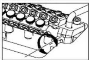
natural_image
Technical line drawing of an engine cylinder head assembly with no visible text or symbols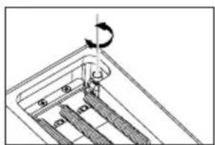
natural_image
Mechanical assembly diagram showing a rotating component with a curved arrow indicating rotation (no text or symbols)注
natural_image
Pure mechanical diagram showing a lever and pivot (no text or symbols)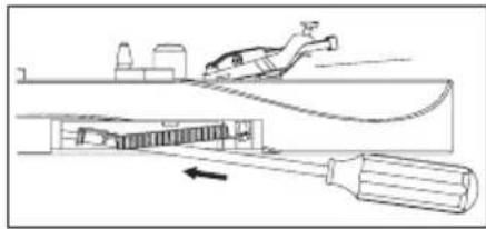
natural_image
Diagram of a mechanical device with a tool and spring, showing internal components and motion direction (no text or symbols)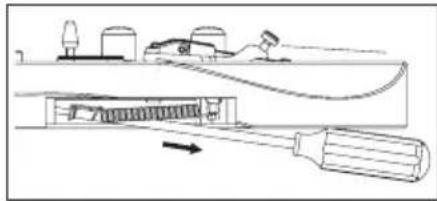
natural_image
Technical line drawing of a mechanical device with a handle and internal components (no text or symbols)度
natural_image
Mechanical assembly diagram showing a tool interacting with a bracket (no text or symbols)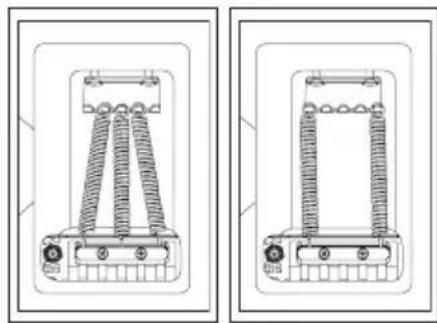
natural_image
Technical line drawing of two mechanical components with coiled springs and mounting holes (no text or symbols)注
natural_image
Mechanical assembly diagram showing gear and shaft components with rotational motion (no text or symbols)调整八音
natural_image
Technical line drawing of a mechanical assembly with rotating components (no text or symbols)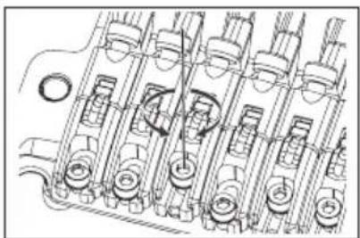
natural_image
Technical line drawing of internal combustion engine components (no text or labels)natural_image
Technical line drawing of a mechanical assembly with multiple cylindrical components and rotational arrows (no text or symbols)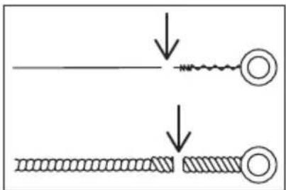
natural_image
Diagram showing two stages of a coiled spring or wire wound, with no text or symbols present.natural_image
Mechanical assembly diagram showing a rotating component with multiple rollers (no text or symbols)简介
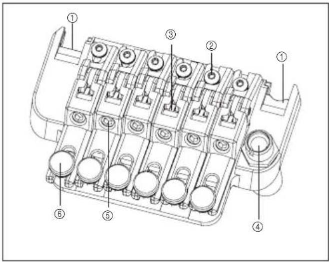
后2
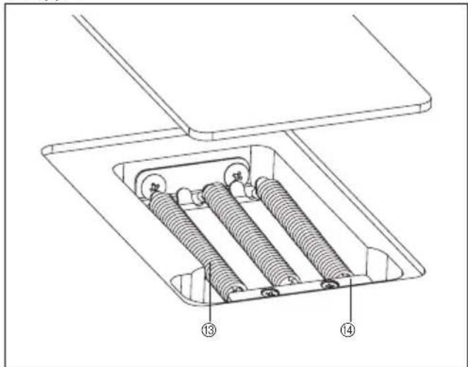
安装摇把
natural_image
Technical line drawings of mechanical components, one showing a pipe inserted into a housing and the other showing a valve assembly (no text or symbols present)颤音器角调整/零点系统调整
- 不配备零点系统的型号
natural_image
Technical diagram of an internal mechanical assembly with springs and housing (no text or labels)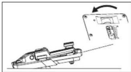
natural_image
Technical line drawing of a mechanical component with an arrow indicating rotation (no text or symbols)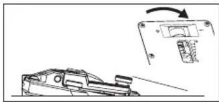
natural_image
Technical line drawing of a mechanical component with an inset showing a close-up view of a component (no text or symbols present)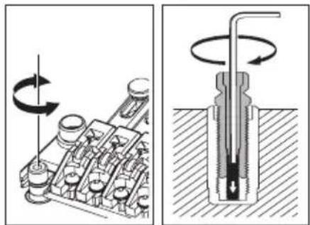
natural_image
Mechanical assembly diagram showing a rotating component and a cross-sectional view of a mechanical component (no text or symbols)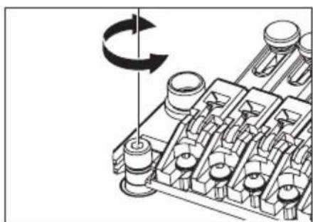
natural_image
Mechanical assembly diagram showing a rotating component with no visible text or symbols注
natural_image
Technical line drawing of a mechanical assembly with no visible text or symbols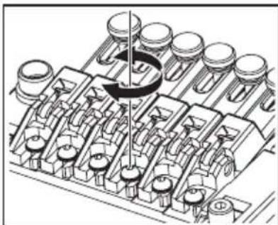
natural_image
Technical illustration of a mechanical assembly with multiple components and a central rotating element (no text or symbols)度
natural_image
Technical line drawing of a mechanical housing or bracket assembly (no text or symbols visible)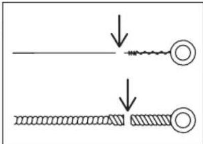
注
natural_image
Technical line drawing of a mechanical assembly with multiple cylindrical components and a central shaft (no text or symbols)■ 简介
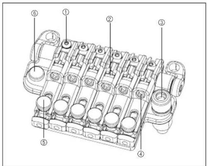
① 琴码锁定螺栓
② 琴弦固定块
③颤音臂插孔
④ 琴弦止动螺栓
⑤ 微调螺栓
⑥ 八音调整螺栓
后
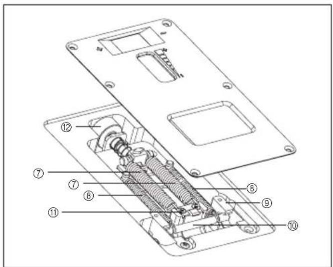
natural_image
Technical line drawing of a mechanical assembly with pipes and gears (no text or symbols)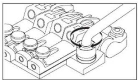
natural_image
Technical line drawing of a mechanical assembly with no visible text or symbols颤音器角调整/零点系统调整
natural_image
Technical line drawing of mechanical components with spring and housing (no text or symbols)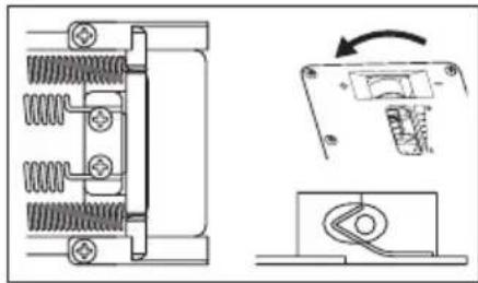
natural_image
Technical line drawing of a mechanical component with spring and housing, showing assembly and disassembly views (no text or symbols)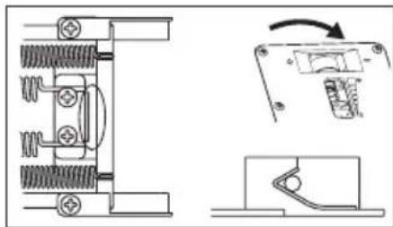
natural_image
Technical line drawing of a mechanical assembly with spring-loaded components and a close-up view of a switch mechanism (no text or symbols)禁用零点系统(将颤音模块当做普通FLOATING(浮动式)颤音器使用)
natural_image
Technical diagram of an internal mechanical assembly with springs and housing (no text or labels)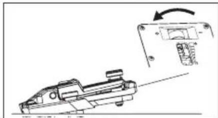
natural_image
Technical line drawing of a mechanical component with an arrow indicating rotation (no text or symbols present)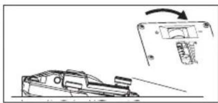
natural_image
Technical line drawing of a mechanical device with an inset showing a component being adjusted (no text or symbols present)natural_image
Mechanical assembly diagram showing a rotating shaft and housing components (no text or labels)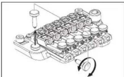
natural_image
Technical diagram of a mechanical component with no visible text or symbols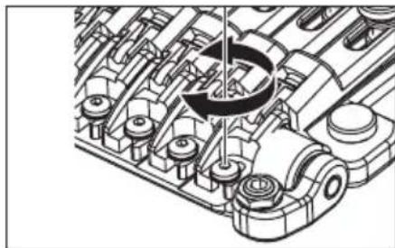
natural_image
Technical illustration of an internal combustion engine assembly (no text or symbols visible)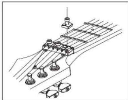
natural_image
Technical line drawing of a guitar fretboard with suspension components (no text or symbols)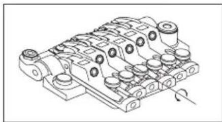
natural_image
Technical line drawing of a mechanical component with multiple cylindrical features and mounting holes (no text or symbols)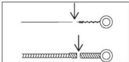
natural_image
Diagram showing two stages of a mechanical or electrical component with arrows indicating motion (no text or symbols)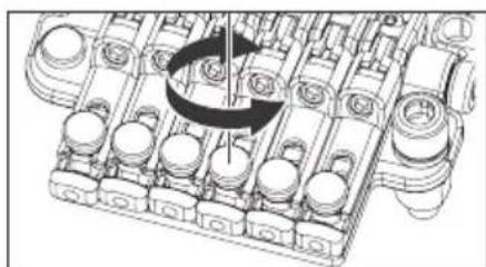
natural_image
Mechanical assembly diagram showing a rotating component with no visible text or symbols■ 简介
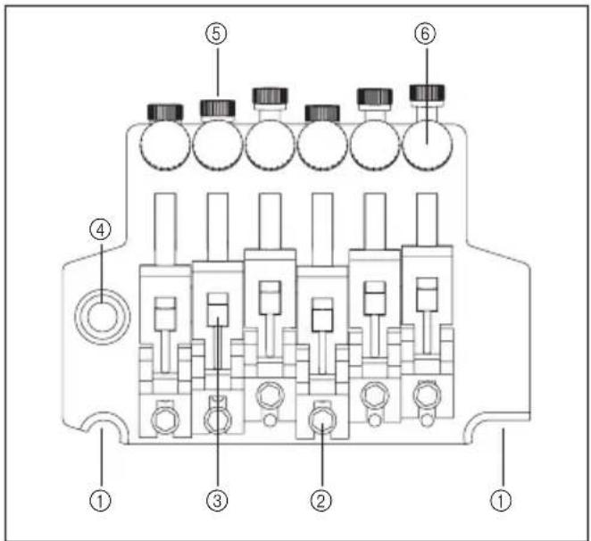
⑤ 琴弦止动螺栓
⑥ 微调螺栓
⑦颤音器弹簧
⑧ 弹簧锁
安装摇把
natural_image
Line drawing of a mechanical component or tool (no text or symbols)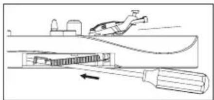
natural_image
Technical line drawing of a mechanical assembly with a tool and component, no visible text or symbols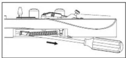
natural_image
Technical line drawing of a mechanical assembly with a tool and component, no visible text or symbols度
natural_image
Technical diagram showing a mechanical assembly with rotating components and a close-up of a component with a downward arrow (no text or symbols)更换琴弦
natural_image
Technical diagram showing mechanical assembly with rotating components and a close-up of a device (no text or symbols)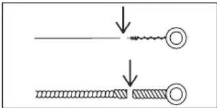
注
① 琴码锁定螺栓
②顛音臂插孔
③ 八音调整螺栓
后
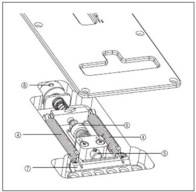
natural_image
Mechanical assembly diagram showing a pipe inserted into a piston component (no text or labels)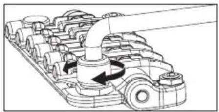
natural_image
Mechanical assembly diagram showing a motor or conveyor system with rotating components and directional arrows (no text or labels)调整颤音器角度
natural_image
Line drawing of a vehicle with no visible text, numbers, or symbols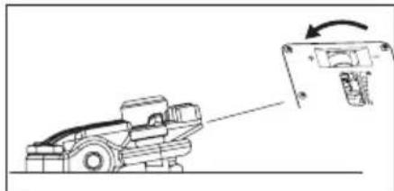
natural_image
Diagram of a mechanical device with an arrow indicating rotation or change, no text or symbols present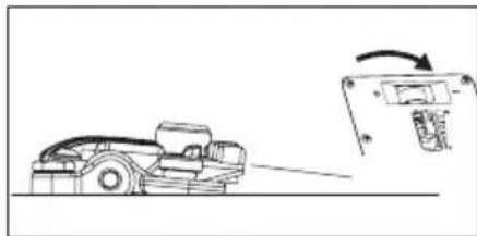
natural_image
Diagram showing a vehicle on a road with an arrow indicating motion or change, next to a mechanical component (no text or symbols present)轴杆止动器
natural_image
Mechanical assembly diagram showing a clamping device with springs and adjustment knobs (no text or labels)调整弦高
natural_image
Mechanical assembly diagram showing a rotating shaft and housing components (no text or labels)调整八音
度
natural_image
Mechanical assembly diagram showing a motor with rotating wheels and a pin (no text or labels)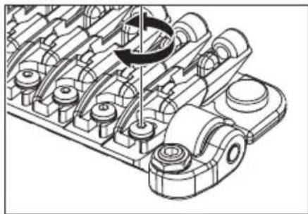
natural_image
Mechanical assembly diagram showing gear and housing components with a circular arrow indicating rotation (no text or labels)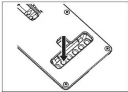
natural_image
Technical diagram showing a mechanical component with an arrow indicating assembly or insertion (no text or symbols present)安装摇把
natural_image
Pure mechanical diagram of a lever handle connecting two blocks (no text or symbols)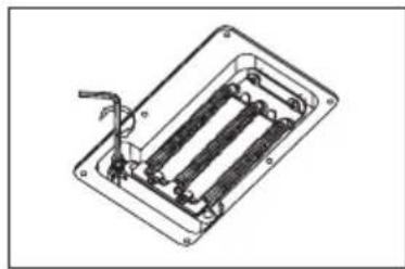
natural_image
Technical line drawing of a mechanical or electrical component with internal parallel slots and a handle (no text or symbols)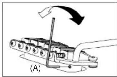
natural_image
Mechanical assembly diagram showing a lever mechanism with motion arrows (no text or symbols)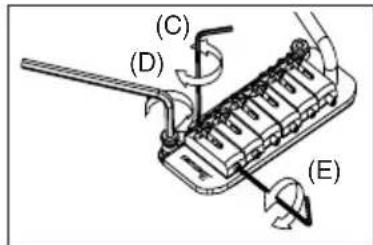
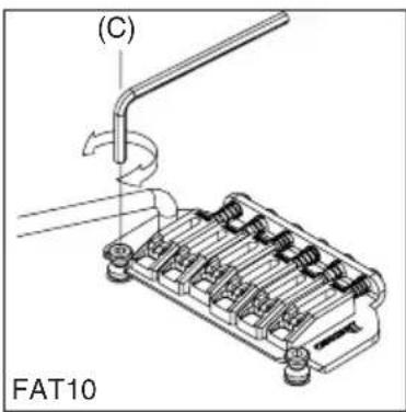
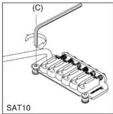
调八音(SAT PRO2)
调八音(FAT10/SAT10)
natural_image
Technical line drawing of a mechanical component with no visible text or symbols调整八音和弦高(FAT6/STD)
度
natural_image
Diagram of a mechanical device with rotating components and directional arrows (no text or symbols)更换琴弦
natural_image
Mechanical assembly diagram showing a bracket with springs and a tool, no text or symbols presentFAT/SAT(FAT6除外)调整摇把弹簧
natural_image
Technical illustration of a mechanical assembly with springs and a tool (no text or symbols)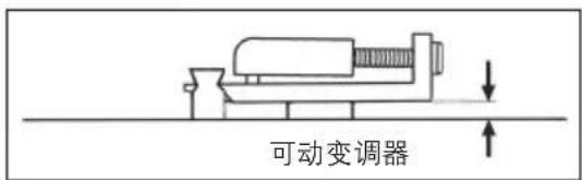
Guitar Electronics
H-S-H (5-WAY)

H-H (5-WAY)
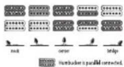
S-S-H (5-WAY)
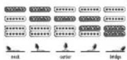
EGEN
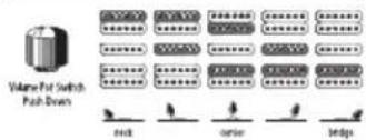
SA360
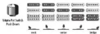
FRM
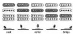
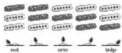
AT
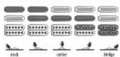
R05500H
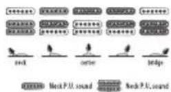
H-H (3-WAY)
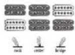
XPT700
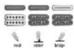
JS
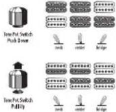
TRI-SOUND (NECK P.U.)
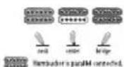
TRI-SOUND (BRIDGE P.U.)
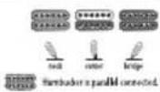
APEX
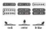
Guitar Controls
1-V, 1-T, 5 WAY LEVER SWITCH
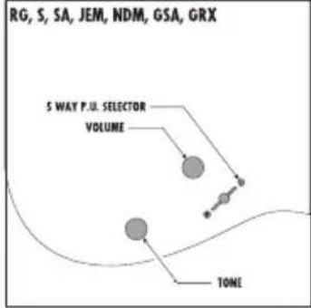
flowchart
graph TD
    A["5 WAY P.I. SELECTOR VOLUME"] --> B["Volume"]
    C["TONE"] --> D["Ground"]
    style A fill:#ccc,stroke:#333
    style B fill:#ccc,stroke:#333
    style C fill:#ccc,stroke:#333
    style D fill:#ccc,stroke:#333
1-V, 1-T, 3 WAY LEVER SWITCH
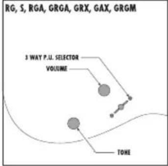
flowchart
graph TD
    A["3 WAY P.U. SELECTOR"] --> B["VOLUME"]
    B --> C["TOKE"]
    C --> D["GRX"]
    C --> E["GAX"]
    C --> F["GRGM"]
1-V, 1 PRE-SET EQ, 3 WAY TOGGLE SWITCH
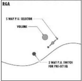
flowchart
graph TD
    A["5 WAY P.U. SELECTOR"] --> B["VOLUME"]
    B --> C["2 WAY P.U. SWITCH FOR PRE-SET IQ"]
    C --> D["Feedback Loop"]
    D --> A
1-V, 3 WAY TOGGLE SWITCH
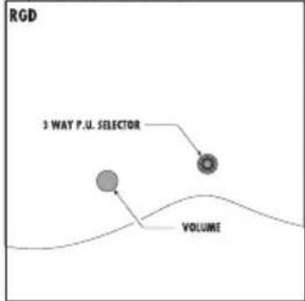
flowchart
graph TD
    A["3 WAY P.U. SELECTOR"] --> B["VOLUME"]
    C["Terminal Node"] --> B
1-V, 1-T, 3 WAY TOGGLE SWITCH
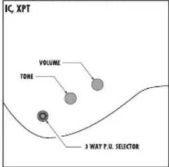
flowchart
graph TD
    A["IC, XPT"] --> B["VOLUME"]
    B --> C["TONE"]
    C --> D["3 WAY P.U. SELECTOR"]
1-V, 3 WAY TOGGLE SWITCH
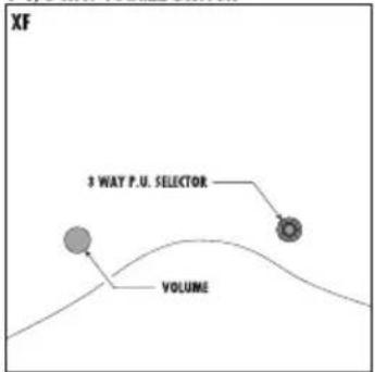
1-V. 3 WAY TOGGLE SWITCH
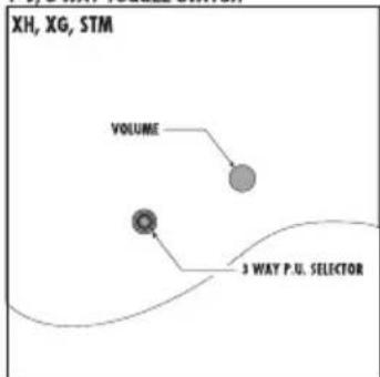
flowchart
graph TD
    A["VOLUME"] --> B["3 WAY P.U. SELECTOR"]
    C["XH, XG, STM"] --> A
1-V, 1-T, 3 WAY TOGGLE SWITCH
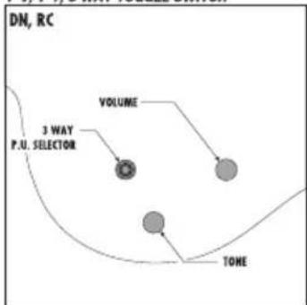
flowchart
graph TD
    A["3 WAY P.U. SELECTOR"] --> B["VOLUME"]
    B --> C["TONE"]
    style A fill:#f9f,stroke:#333
    style B fill:#ccf,stroke:#333
    style C fill:#cfc,stroke:#333
1-V, 1-T, 5 WAY LEVER SWITCH
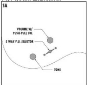
flowchart
graph TD
    A["5 WAY P.U. SELECTOR"] --> B["VOLUME W/ PUSH-PULL SW."]
    A --> C["TONE"]
    A --> D["SA"]
1-V, 2-T, 5 WAY LEVER SWITCH
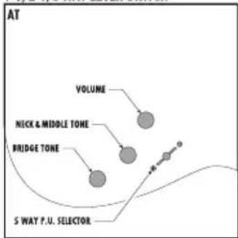
flowchart
graph TD
    A["VOLUME"] --> B["NICK & MIDDLE TONE"]
    B --> C["BRIDGE TONE"]
    C --> D["5 WAY P.U. SELECTOR"]
    style A fill:#ccc,stroke:#333
    style B fill:#ccc,stroke:#333
    style C fill:#ccc,stroke:#333
    style D fill:#ccc,stroke:#333
flowchart
graph TD
    A["3 WAY P.U. SELECTOR VOLUME"] --> B["TONE W/ COIL TAP ON/OFF SW."]
1-V, 1-T, 5 WAY LEVER SWITCH

flowchart
graph TD
    A["FRM"] --> B["S WAY P.U. SELECTOR"]
    B --> C["TONE"]
    C --> D["VOLUME"]
    D --> E["Output"]
1-V
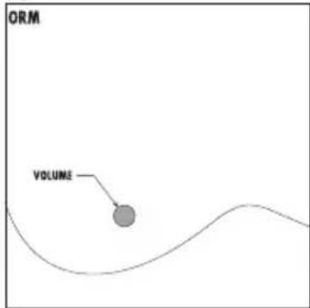
1-V, KILL SWITCH, 3 WAY LEVER SWITCH
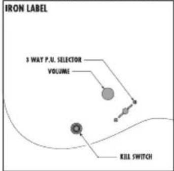
flowchart
graph TD
    A["3 WAY P.U. SELECTOR"] --> B["VOLUME"]
    B --> C["KILL SWITCH"]
    C --> D["Final Output"]
1-V, 1-T, 3 WAY TOGGLE SWITCH
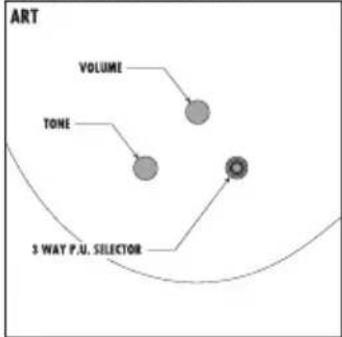
flowchart
graph TD
    A["VOLUME"] --> B["TONE"]
    B --> C["3 WAY P.U. SELECTOR"]
2-V, 1-T, 3 WAY TOGGLE SWITCH
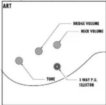
2-V. 1-T. 3 WAY TOGGOLE SWITCH
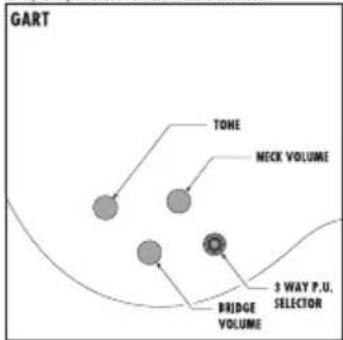
2-V, 2-T, 3 WAY TOGGLE SWITCH.
TRI-SOUND NECK BRIDGE
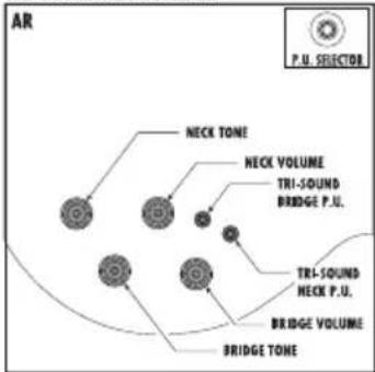
1-V, 1-T, 3 WAY TOGGLE SWITCH
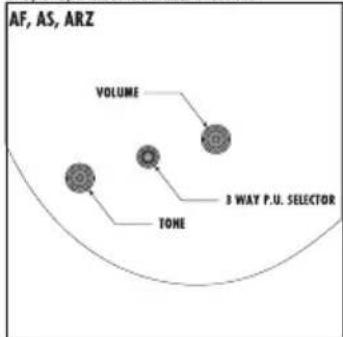
flowchart
graph TD
    A["AF, AS, ARZ"] --> B["VOLUME"]
    A --> C["TONE"]
    B --> D["3 WAY P.U. SELECTOR"]
2-V, 2-T, 3 WAY TOGGLE SWITCH
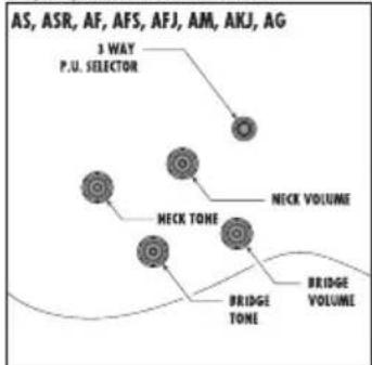
flowchart
graph TD
    A["AS, ASR, AF, AFS, AFJ, AM, AKJ, AG"] --> B["P.U. SELECTOR"]
    B --> C["Neck Volume"]
    C --> D["NECK TONE"]
    D --> E["BRIDGE VOLUME"]
    E --> F["BRIDGE TONE"]
    F --> G["BRIDGE VOLUME"]
2-V, 2-T, 3 WAY TOGGLE SWITCH
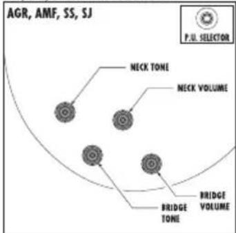
1-V, 1-T
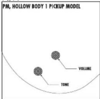
2-V, 2-T, 3WAY TOGGLE SWITCH, TRI-SOUND NECK P.U.
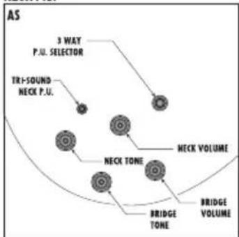
flowchart
graph TD
    A["3 WAY P.JL. SELECTOR"] --> B["NECK VOLUME"]
    C["TRI-SOUND NECK P.U."] --> D["NECK TONE"]
    D --> E["BRIDGE VOLUME"]
    F["BRIDGE TONE"] --> G["NECK VOLUME"]
    H["NECK VOLUME"] --> I["BRIDGE VOLUME"]
This is to certify that the aforementioned equipments fully conform to protection
requirements of the following EC council directives. DIRECTIVES:89/336/EEC Electromagnetic compatibility
CE
The followings complies with the requirements of the EMC Directive 2004/108/EC of the European Union.
CE


- はじめにお読みください
- 安全にお使いいただくために
- 注意
- 楽器を振り回さないでください。
- 極端な大音量で鳴らさないでください。
- ご注意
- アジャスタブルアーチトップブリッジ
- イントネーション調整
- 弦交换
- ロッキングトレモロ
- EDGE トレモロブリッジ
- トレモロの取り付け角度調整
- 弦高調整
- トレモロアームの取り付け
- ・ゼロ・ポイント・システム搭載モデル
- ファイン・チューニング
- Memo
- STRING REPLACEMENT
- INTONATION
- NECK ADJUSTMENT
- CLEANING
- BATTERY
- Guitar Bridges
- GIBRALTAR III (GUITAR & BASS), CB3, & FULL TUNE III, ART1, ART2
- HARDTAIL BRIDGE
- GIBRALTER STANDARD BRIDGE (7-STRING / 8-STRING MODELS)
- GIBRALTAR BRIDGE 08 / QUICK CHANGE 08 TAILPIECE
- ADJUSTABLE ARCH TOP BRIDGE
- Vintage Vibrato
- Tailpieces
- QUIK CHANGE TAILPIECES
- Tight-End bridge / Tight-End R bridge (for 6-string and 7-string)
- ADJUSTING THE ACTION
- ADJUSTING THE INTONATION
- TIGHT-TUNE BRIDGE
- STUD LOCK FUNCTION
- REPLACING THE STRINGS
- Locking Bridge
- FX EDGE III/FX EDGE III-8 BRIDGE
- FINE TUNING
- Locking Tremolos
- EDGE TREMOLO BRIDGE
- ATTACHING THE TREMOLO ARM
- ADJUSTING THE TREMOLO ATTACHMENT ANGLE
- TREMOLO SPRINGS
- STUD LOCK
- ANGLE ADJUSTMENT / ZERO POINT SYSTEM ADJUSTMENT
- • Models not equipped with the zero point system
- - Models equipped with the zero point system
- TREMOLO SPRING / ZERO POINT SYSTEM
- - Models not equipped with the zero point system
- DISABLING THE ZERO POINT SYSTEM (USING THE UNIT AS A CONVENTIONAL FLOATING
- Non Locking Tremolo
- SynchroniZR
- ARM-UP STOPPER
- STRING HEIGHT ADJUSTMENT
- INTONATION ADJUSTMENT
- TREMOLO ARM INSTALLATION
- TREMOLO ARM ADJUSTMENT (SAT PRO2)
- ARM ROTATION TORQUE
- ADJUSTING THE STRING HEIGHT (SAT PRO2)
- ADJUSTING THE STRING HEIGHT (FAT10/SAT10)
- INTONATION ADJUSTMENT (SAT PRO2)
- INTONATION ADJUSTMENT (FAT10/SAT10)
- ADJUSTING THE INTONATION & THE STRING HEIGHT (FAT 6/STD)
- FAT/SAT (EXPECT FAT6) ADJUSTING THE TREMOLO SPRING
- Hinweis
- GIBRALTAR STANDARDSTEG (7-SAITIGE / 8-SAITIGE MODELLE)
- FX-EDGE-III-/FX-EDGE-III-8-STEG
- WECHSELN DER SAITEN
- EDGE-TREMOLOSTEG
- TREMOLOFEDERN
- MONTAGE DES TREMOLOHEBELS
- DEAKTIVIEREN DES NULLPUNKTSYSTEMS (VERWENDUNG ALS HERKÖMMLICHES SCHWEBENDES TREMOLO)
- STOPPFUNKTION BEI ANGEHOBENEM HEBEL
- TREMOLOARM-INSTALLATION
- ERSETZEN DER SAITEN
- FAT/SAT (AUSGENOMMEN FAT6) EINSTELLEN DER TREMOLOFEDER
- REPLACEMENT DES CORDES
- Mémo
- CHEVALET À TABLE BOMBÉE RÉGLABLE
- Vibrato Vintage
- RÉGLAGE DE L'INTONATION
- CHEVALET FX EDGE III/FX EDGE III-8
- FX Edge
- REMPLACEMENT DES CORDES
- CHEVALET VIBRATO EDGE
- RÉGLAGE DE L'ANGLE D'ATTAQUE DU VIBRATO
- Arrière 2
- FIXATION DE LA TIGE DE VIBRATO
- ZERO POINT
- RÉGLAGE DE L'ANGLE DU VIBRATO/RÉGLAGE DU SYSTÈME ZERO POINT
- DÉSACTIVATION DU SYSTÈME ZERO POINT (UTILISATION DE L'UNITÉ COMME UN VIBRATO FL OTTANT TRADITIONNEL)
- RÉGLAGE DE LA HAUTEUR DES CORDES
- INSTALLATION DE LA TIGE DU VIBRATO
- RÉGLAGE DE LA HAUTEUR DES CORDES (FAT20/FAT10/SAT10
- RÉGLAGE DE L'INTONATION (FAT10/SAT10)
- RÉGLAGE DE L'INTONATION ET DE LA HAUTEUR DES CORDES (FAT 6/STD)
- RÉGLAGE DU RESSORT DE VIBRATO
- Mantenimiento
- Nota
- PUENTE GIBRALTAR ESTÁNDAR (MODELOS DE 7/8 CUERDAS)
- PUENTE ARCH TOP AJUSTABLE
- PUENTE FX EDGE III/FX EDGE III-8
- Locking Trémolos
- AJUSTE DEL ÁNGULO DEL TRÉMOLO Y DEL SISTEMA ZERO POINT
- - Modelos sin sistema Zero Point
- Tope de palanca arriba
- Octavación
- Cambio de cuerdas
- FAT/SAT (EXCEPTO FAT6) AJUSTE DE LOS MUELLES DEL TRÉMOLÓ
- Manutenzione
- PONTE GIBRALTAR STANDARD (MODELLI A 7 E 8 CORDE)
- PONTE FX EDGE III/FX EDGE III-8
- PONTE TREMOLO EDGE
- MOLLE DEL TREMOLO
- Panoramica
- Retro 2
- MONTAGGIO DELLA LEVA TREMOLO
- DISABILITAZIONE DEL SISTEMA ZERO POINT (UTILIZZO DELL'UNITÀ COME TREMOLO FL OTTANTE TRADIZIONALE)
- ARRESTO ARM-UP
- REGOLAZIONE DELL'ALTEZZA DELLE CORDE
- MONTAGGIO DEL BRACCIO DEL TREMOLO
- FAT/SAT (TRANNE FAT6) REGOLAZIONE DELLA MOLLA DEL TREMOLO
- 维护保养
- 注
- GIBRALTER STANDARD 琴桥 (7-弦/8-弦型号)
- 可调拱形面板琴桥
- 获得醇厚的颤音
- 调整八音
- 换弦
- 固定琴桥
- FX EDGE III/FX EDGE III-8 琴桥
- 更换琴弦
- 弦锁摇把
- EDGE 颤音琴桥
- 安装摇把
- 颤音器弹簧
- 颤音器角调整/零点系统调整
- - 不配备零点系统的型号
- 禁用零点系统(将颤音模块当做普通FLOATING(浮动式)颤音器使用)
- 度
- 调整颤音器角度
- 轴杆止动器
- 调整弦高
- 调八音(SAT PRO2)
- 调八音(FAT10/SAT10)
- 调整八音和弦高(FAT6/STD)
- FAT/SAT(FAT6除外)调整摇把弹簧
- Guitar Electronics
- Guitar Controls
Brand : IBANEZ
Model : GIO GSR205
Category : Guitar