
Attune II WXCC411 - Controller PANASONIC - Free user manual and instructions
Find the device manual for free Attune II WXCC411 PANASONIC in PDF.

| Product Type | Controller for wireless drive-through intercom system |
| Brand | Panasonic |
| Model | Attune II WXCC411 |
| Dimensions (W × H × D) | 375 mm × 275 mm × 50 mm |
| Weight | Approx. 1.9 kg (without wall mount) |
| Power Supply | 100-120 V AC, 50/60 Hz |
| Power Consumption | 17 W |
| Operating Frequency | 1921.536 - 1928.448 MHz (DECT 1.9 GHz band) |
| Display | 7-inch color LCD screen (WVGA 800×480) with LED backlight |
| Touch Screen | 7.8-inch resistive technology |
| Number of Audio Channels | 1 (mono) for single lane |
| Main Interfaces | Euroblock for microphones, speakers, lines, detectors, alerts; RS-232C; Ethernet 10/100BASE-TX; NTSC video output (RCA); SD card slot |
| Key Features | Customer voice communication, staff intercom, ID registration (up to 32 headsets), network camera control (up to 4), parameter backup/restore via SD card, greeting message scheduler, alerts (audible, email, relay output) |
| Number of Registrable Headsets | 32 (all-in-one headsets or belt pack modules) |
| Audio Connections | OUT MIC, OUT SP (8 Ω), LINE IN/OUT, AUX MIC/SP (8 Ω), all on Euroblock connectors |
| Safety | Mandatory grounding, surge protection, FCC Part 15 and IC compliance, 20 cm distance from body |
| Operating Temperature | -10 °C to +50 °C |
| Operating Humidity | 20% to 90% (non-condensing) |
| Supplied Accessories | Power cord, wall mount, cable clamp, user manual |
| Touch Screen Cleaning | Soft dry cloth; do not use liquid cleaners, alcohol, benzene; do not press hard |
Frequently Asked Questions - Attune II WXCC411 PANASONIC
User questions about Attune II WXCC411 PANASONIC
0 question about this device. Answer the ones you know or ask your own.
Ask a new question about this device
Download the instructions for your Controller in PDF format for free! Find your manual Attune II WXCC411 - PANASONIC and take your electronic device back in hand. On this page are published all the documents necessary for the use of your device. Attune II WXCC411 by PANASONIC.
USER MANUAL Attune II WXCC411 PANASONIC
Operating Instructions
Installation Instructions provided
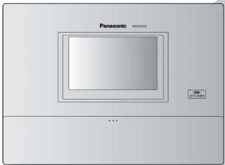
Center Module
Model No. WX-CC411
WX-CC412

Before attempting to connect or operate this product, please read these instructions carefully and save this manual for future use. No model number suffix is shown in this Operating Instructions.
Safety precautions
FEDERAL COMMUNICATIONS COMMISSION INTERFERENCE STATEMENT
This equipment has been tested and found to comply with the limits for a Class A digital device, pursuant to part 15 of the FCC Rules. These limits are designed to provide reasonable protection against harmful interference when the equipment is operated in a commercial environment. This equipment generates, uses, and can radiate radio frequency energy and, if not installed and used in accordance with the instruction manual, may cause harmful interference to radio communications. Operation of this equipment in a residential area is likely to cause harmful interference in which case the user will be required to correct the interference at his own expense.
Changes or modifications not expressly approved by the party responsible for compliance could void the user's authority to operate the equipment.
This transmitter must not be co-located or operated in conjunction with any other antenna or transmitter.
This equipment complies with FCC/IC radiation exposure limits set forth for an uncontrolled environment and meets the FCC radio frequency (RF) Exposure Guidelines in Supplement C to OET65 and RSS-102 of the IC radio frequency (RF) Exposure rules. This equipment should be installed and operated keeping the radiator at least 20 cm or more away from person's body (excluding extremities: hands, wrists, feet and ankles).
This device complies with Part 15 of FCC Rules and Industry Canada licence-exempt RSS standard(s). Operation is subject to the following two conditions: (1) this device may not cause interference, and (2) this device must accept any interference, including interference that may cause undesired operation of this device.

CAUTION
RISK OF ELECTRIC SHOCK DO NOT OPEN

CAUTION: TO REDUCE THE RISK OF ELECTRIC SHOCK, DO NOT REMOVE COVER (OR BACK).
NO USER SERVICEABLE PARTS INSIDE.
REFER TO SERVICING TO QUALIFIED SERVICE PERSONNEL.

The lightning flash with arrowhead symbol, within an equilateral triangle, is intended to alert the user to the presence of uninsulated “dangerous voltage” within the product’s enclosure that may be of sufficient magnitude to constitute a risk of electric shock to persons.

The exclamation point within an equilateral triangle is intended to alert the user to the presence of important operating and maintenance (service) instructions in the literature accompanying the appliance.
WARNING:
• This apparatus must be earthed.
- Apparatus shall be connected to a main socket outlet with a protective earthing connection.
- The mains plug or an appliance coupler shall remain readily operable.
- To reduce the risk of fire or electric shock, do not expose this apparatus to rain or moisture.
- The apparatus should not be exposed to dripping or splashing and that no objects filled with liquids, such as vases, should be placed on the apparatus.
- All work related to the installation of this product should be made by qualified service personnel or system installers.
- To prevent injury, this apparatus must be securely attached to the floor/wall in accordance with the installation instructions.
- The connections should comply with local electrical code.
- The risk of hearing impairment due to exposure to excessive sound levels may be reduced by listening at lower volumes and for shorter durations.
- Operating near 1.9 GHz electrical appliances may cause interference. Move away from the electrical appliances.
- This transmitter must not be co-located or operated in conjunction with any other antenna or transmitter.
MEDICAL:
Consult the manufacturer of any personal medical devices, such as pacemakers, to determine if they are adequately shielded from external RF (radio frequency) energy. (The unit operates in the frequency range of 1.92 GHz to 1.93 GHz, and the power output level is 115mW max)
Do not use the unit in health care facilities if any regulations posted in the area instruct you not to do so. Hospitals or health care facilities may be using equipment that could be sensitive to external RF (radio frequency) energy.
- The installation shall be carried out in accordance with all applicable installation rules.
- To prevent fire or electric shock hazard, do not expose this apparatus to rain or moisture.
For U.S.A.
The model number and serial number of this product may be found on the surface of the unit.
You should note the model number and serial number of this unit in the space provided and retain this book as a permanent record of your purchase to aid identification in the event of theft.
Model No. ____
Serial No. ____
For U.S.A.
CAUTION:
The FCC ID number for this radio equipment is listed below.
FCC ID: ACJ9TAWX-CC411
FCC ID: ACJ9TAWX-CC412
For U.S.A.
This product contains a CR Coin Cell Lithium Battery which contains Perchlorate Material – special handling may apply. See
www.dtsc.ca/gov/hazardouswaste/perchlorate/

A lithium-ion battery that is recyclable powers the product you have purchased. Please call 1-800-8-BATTERY for information on how to recycle this battery.
CAUTION:
- Danger of explosion if battery is incorrectly replaced. Replace only with the same or equivalent type.
- These servicing instructions are for use by qualified service personnel only. To reduce the risk of electric shock do not perform any servicing other than that contained in the operating instructions unless you are qualified to do so.
- Any changes or modifications not expressly approved by the party responsible for compliance could void the user's authority to operate the equipment.
- Shielded (STP) LAN cables must be used with this unit to ensure compliance with EMC standards.
For Canada
ICES-003
CAN ICES-3(A)/NMB-3(A)
For Canada
RSS-Gen
- Under Industry Canada regulations, this radio transmitter may only operate using an antenna of a type and maximum (or lesser) gain approved for the transmitter by Industry Canada. To reduce potential radio interference to other users, the antenna type and its gain should be so chosen that the equivalent isotropically radiated power (e.i.r.p.) is not more than that necessary for successful communication.
IMPORTANT SAFETY INSTRUCTIONS
1) Read these instructions.
2) Keep these instructions.
3) Heed all warnings.
4) Follow all instructions.
5) Do not use this apparatus near water.
6) Clean only with dry cloth.
7) Do not install near any heat sources such as radiators, heat registers, stoves, or other apparatus (including amplifiers) that produce heat.
8) Do not defeat the safety purpose of the polarized or grounding-type plug. A polarized plug has two blades with one wider than the other. A grounding type plug has two blades and a third grounding prong. The wide blade or the third prong are provided for your safety. If the provided plug does not fit into your outlet, consult an electrician for replacement of the obsolete outlet.
9) Protect the power cord from being walked on or pinched particularly at plugs, convenience receptacles, and the point where they exit from the apparatus.
10) Only use attachments/accessories specified by the manufacturer.
11) Use only with the cart, stand, tripod, bracket, or table specified by the manufacturer, or sold with the apparatus. When a cart is used, use caution when moving the cart/apparatus combination to avoid injury from tip-over.
12) Unplug this apparatus during lightning storms or when unused for long periods of time.
13) Refer all servicing to qualified service personnel. Servicing is required when the apparatus has been damaged in any way, such as power-supply cord or plug is damaged, liquid has been spilled or objects have fallen into the apparatus, the apparatus has been exposed to rain or moisture, does not operate normally, or has been dropped.
Safety precautions 2
Before use 5
Preface 5
Features 5
System diagram 5
Operation 6
Concerning the Operating Instructions 7
Standard accessories 7
Trademarks and registered trademarks 7
Abbreviations 8
Limitation of liability 8
Disclaimer of warranty 8
Network security 8
Precautions 9
Operating precautions 9
Installation precautions 10
Major operating controls and their functions ..... 11
Front panel 11
Terminal block 12
Side panel 13
Screen 14
Description of screens 15
Basic screen 15
Setting Information screen 16
Password input screen 18
Camera monitoring screen 18
Quick Operation screen 19
Related devices 20
Installation procedures 21
Deciding on where to install the Center Module ..... 21
Installation 21
Connections 24
Opening the connector cover 24
Securing the power cord 24
Wiring the Euroblock connector 25
Attaching the connector cover 27
Examples of connections 28
Screen operations 29
Basic screen operations 29
Entering the settings 29
Inputting characters 30
Inputting the date and time 30
Adjusting the volume level 30
Operating procedures 31
Basic operations 31
ID Registration 31
Convenient Functions (Other Functions) 33
Troubleshooting 36
Specifications 37
Licenses 39
Preface
The WX-CC411 and WX-CC412 are Center Modules for the wireless intercom systems that are used in drive-thru outlets.
Features
- The WX-CC411 is designed for single lane operation of drive-thru outlets; the WX-CC412 is designed for dual lane operation.
- A system compliant with the 1.9 GHz band DEC standard is used so the voices of the store personnel and customers are heard clearly and distinctly even in open areas, and interference is minimal, resulting in stable communication. * Digital Enhanced Cordless Telecommunications
- A high degree of vocal clarity is ensured by a powerful echo canceller and digital noise reduction (DNR).
- The cabinet supports wall-mounting for easy installation.
- The total number of All-in-One Headsets and Belt Packs that can be registered is 32. Up to four operators can communicate at the same time per lane using All-in-One Headsets and Belt Packs.
- This unit has a 7-Type LCD display with a touch panel, and is easy to operate.
- This unit can be connected to an IP network using Ethernet to enable remote control operations to be performed.
- Using an SD card, it is possible to back up and restore the settings, and save messages unique to the outlet.
- The system contains a scheduler to enable the greeter message to be changed at designated times and reminder messages to be played back automatically.
- Up to four Network Cameras made by Panasonic can be registered, and their images can be monitored on this unit's LCD display.
- Alert signals that have been received can be sent to the All-In-One Headsets or Belt Packs, signals can be output to external devices, and alert emails can be sent to external destinations.
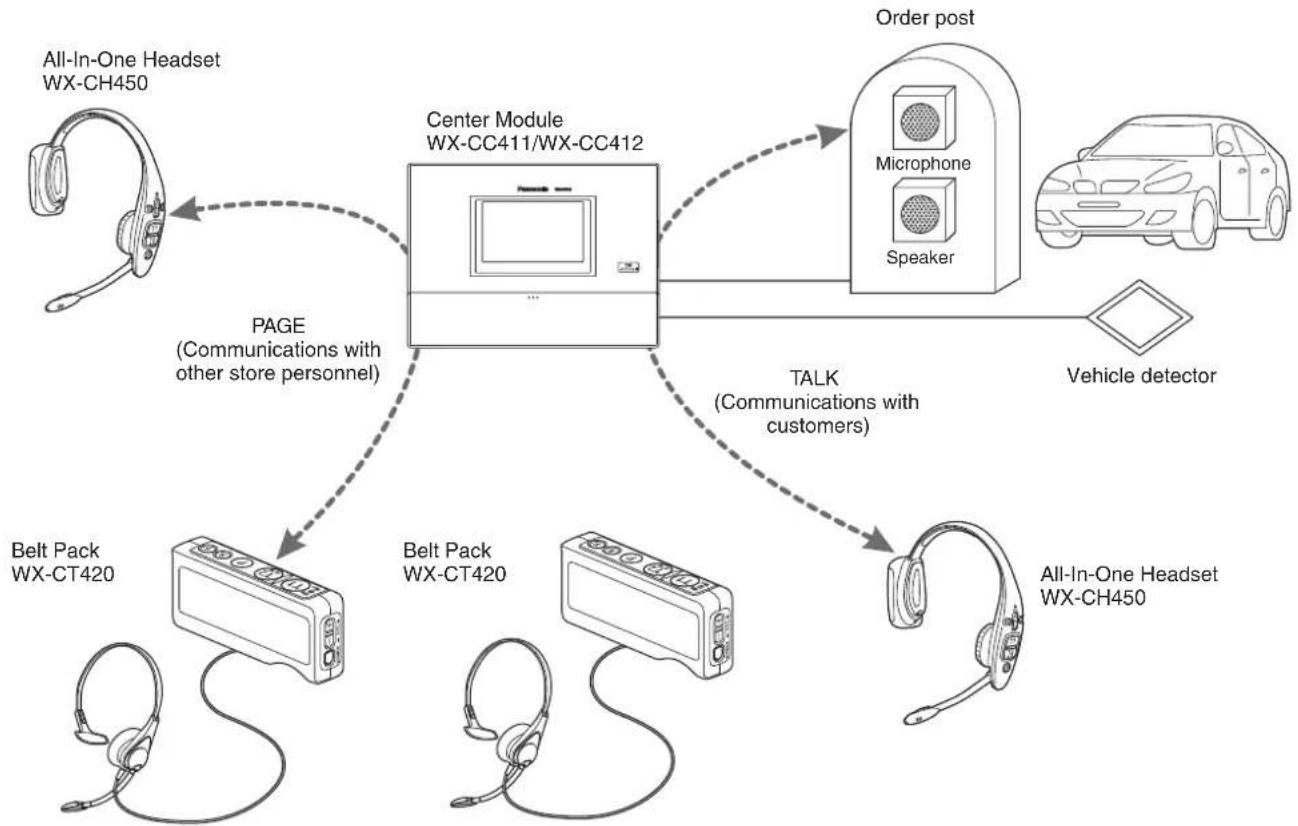
■ System diagram
By connecting the Center Module and All-In-One Headsets or Belt Packs wirelessly, it is possible to communicate between the All-In-One Headsets or Belt Packs or between the All-In-One Headsets or Belt Packs and the customers at the order post.
flowchart
graph TD
    A["All-In-One Headset WX-CH450"] -->|PAGE (Communications with other store personnel)| B["Center Module WX-CC411/WX-CC412"]
    B -->|TALK (Communications with customers)| C["Order post"]
    C --> D["Microphone"]
    C --> E["Speaker"]
    D --> F["Vehicle detector"]
    E --> F
    G["Belt Pack WX-CT420"] --> B
    H["Belt Pack WX-CT420"] --> B
    I["All-In-One Headset WX-CH450"] -->|TALK| J["All-In-One Headset WX-CH450"]
Operation
This system supports the following operations that are suited to drive-thru customers.
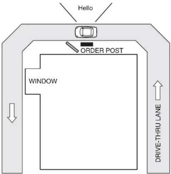
Single lane
Operations in an environment in which only one order post is installed are referred to as "single lane" operations. These lane operations are supported by the WX-CC411.
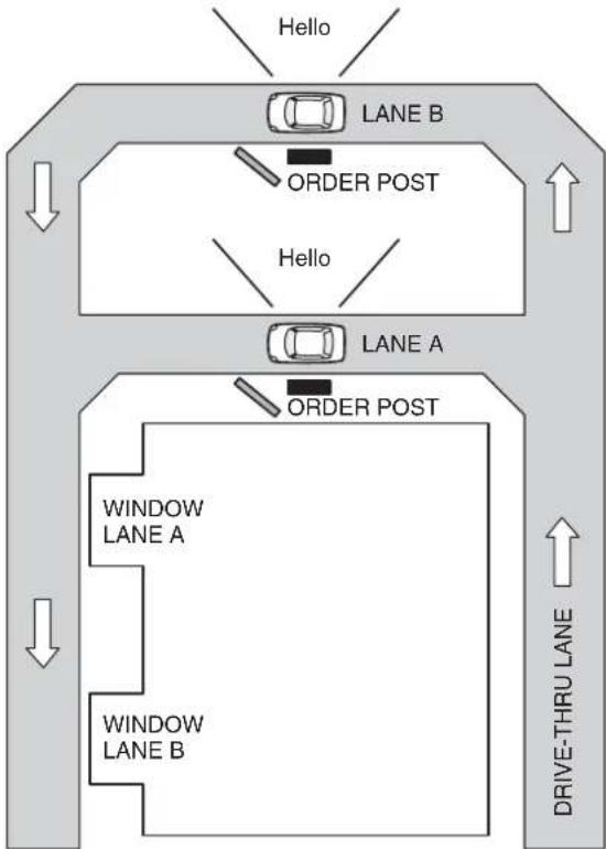
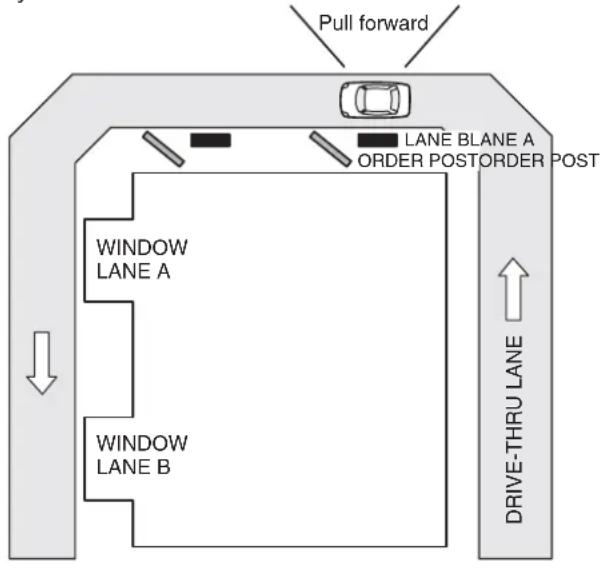
Dual lane
Operations in an environment in which the order posts are installed in parallel are referred to as "dual lane" operations. With dual lane operations, the vehicle detectors for lane A and lane B operate independently of each other, and when each of these vehicle detectors is set to ON, the greeter message for the lane concerned is played back. These lane operations are supported by the WX-CC412.
flowchart
graph TD
    A["HOLO"] --> B["LANE B"]
    B --> C["ORDER POST"]
    C --> D["HOLO"]
    D --> E["LANE A"]
    E --> F["ORDER POST"]
    F --> G["DRIVE-THRU LANE"]
    H["WINDOW LANE A"] --> I["Window LANE B"]
    J["DRIVE-THRU LANE"] --> K["Window LANE B"]
Tandem lane
Operations in an environment in which the order posts are installed in series are referred to as "tandem lane" operations. When the vehicle detector for lane A is OFF and the vehicle detector for lane B is set to ON, a tandem lane message urging the customer to move to lane A is played back.
These lane operations are supported by the WX-CC412.
■ Concerning the Operating Instructions
The Operating Instructions consist of the Operating Instructions
- Operating Instructions
- Operating Instructions
- Operating Instructions
To read PDF files, you will need Adobe® Reader® which is available from Adobe Systems. When Adobe® Reader® is not installed on the PC, download the latest Adobe® Reader® from the Adobe web site and install it.
Important
- Download the “Operating Instructions
■ Standard accessories
Power cord 1 pc.
Wall mounting bracket 1 pc.
Power cord clamp 1 pc.
Clamp (for securing the power cord to the wall) ..... 1 pc.
Operating Instructions (this manual) .... 1 pc.
■ Trademarks and registered trademarks
- Adobe, Acrobat Reader, and Adobe Reader are either registered trademarks or trademarks of Adobe Systems Incorporated in the United States and/or other countries.
• SD, SDHC Logo is a trademark of SD-3C, LLC.
- Other names of companies and products contained in these operating instructions may be trademarks or registered trademarks of their respective owners.
■ Abbreviations
The following abbreviations are used in this document.
SDHC and SD memory cards are referred to as "SD cards".
■ Limitation of liability
THIS PUBLICATION IS PROVIDED "AS IS" WITHOUT WARRANTY OF ANY KIND, EITHER EXPRESS OR IMPLIED, INCLUDING BUT NOT LIMITED TO, THE IMPLIED WARRANTIES OF MERCHANTABILITY, FITNESS FOR ANY PARTICULAR PURPOSE, OR NON-INFRINGEMENT OF THE THIRD PARTY'S RIGHT.
■ Disclaimer of warranty
IN NO EVENT SHALL Panasonic Corporation BE LIABLE TO ANY PARTY OR ANY PERSON, EXCEPT FOR REPLACEMENT OR REASONABLE MAINTENANCE OF THE PRODUCT, FOR THE CASES, INCLUDING BUT NOT LIMITED TO BELOW:
(1) ANY DAMAGE AND LOSS, INCLUDING WITHOUT LIMITATION, DIRECT OR INDIRECT, SPECIAL, CONSEQUENTIAL OR EXEMPLARY, ARISING OUT OF OR RELATING TO THE PRODUCT;
(2) PERSONAL INJURY OR ANY DAMAGE CAUSED BY INAPPROPRIATE USE OR NEGLIGENT OPERATION OF THE USER;
(3) UNAUTHORIZED DISASSEMBLE, REPAIR OR MODIFICATION OF THE PRODUCT BY THE USER;
(4) ANY PROBLEM CAUSING FAILED SIGNAL TRANSMISSION RESULTING IN CONSEQUENTIAL INCONVENIENCE, LOSS OR DAMAGE, ARISING OUT OF CAUSES SUCH AS SYSTEM MALFUNCTION, FAULT, SET UP OR INSTALLATION.
(5) ANY PROBLEM, CONSEQUENTIAL INCONVENIENCE, OR LOSS OR DAMAGE, ARISING OUT OF THE SYSTEM COMBINED BY THE DEVICES OF THIRD PARTY.
(6) PERSONAL INJURY, ANY LOSS OR DAMAGE, ARISING OUT OF THE DROP CAUSED BY THE INCOMPLETE INSTALLATION.
(7) ANY CLAIM OR ACTION FOR DAMAGES, BROUGHT BY ANY PERSON OR ORGANIZATION BEING PHOTOGENIC SUBJECT, DUE TO VIOLATION OF PRIVACY WITH THE RESULT OF THAT SURVEILLANCE-CAMERA'S PICTURE, INCLUDING SAVED DATA, FOR SOME REASON, BECOMES PUBLIC OR IS USED FOR ANY PURPOSE.
(8) LOSS OF REGISTERED DATA CAUSED BY ANY FAILURE.
■ Network security
As you will use this product connected to a network, your attention is called to the following security risks.
(1) Leakage or theft of information through this product
(2) Use of this product for illegal operations by persons with malicious intent
(3) Interference with or stoppage of this product by persons with malicious intent
It is your responsibility to take precautions such as those described below to protect yourself against the above network security risks.
- Use this product in a secured network not connected to the Internet.
- If this product is connected to a network that includes PCs, make sure that the system is not infected by computer viruses or other malicious entities (using a regularly updated anti-virus program, anti-spyware program, etc.).
- Protect your network against unauthorized access by restricting users to those who log in with an authorized user name and password.
- After this unit has been accessed by the administrator, all the web browsers must be closed without fail.
- The administrator's password must be changed at regular intervals.
- Apply measures such as user authentication for the servers and the connected devices to protect your network against leakage or theft of information, including image data, authentication information (user names and passwords), alarm mail information, FTP server information, etc.
■ Operating precautions
- This unit is for indoor use only. It cannot be used outdoors.
Avoid installation in a location where the unit will be exposed to direct sunlight for extended periods or near a cooling or heating appliance.
Otherwise, deformation, discoloration, malfunctioning and/or problems in operation may result. Operate the unit where it will not be splashed or sprayed by water.
- Handle the unit carefully. This product uses parts that may be damaged by improper handling or storage.
- Do not use this unit in an atmosphere where there are flammable gases. Otherwise, an explosion may occur, resulting in injuries.
- Do not install this unit in a location that is susceptible to salt damage or where corrosive gases are given off. Otherwise, the mounting parts will deteriorate, and this unit may fall, resulting in injury or accidents.
- Tighten the screws and bolts using the designated torque. Otherwise, this unit may fall, resulting in injury or accidents.
- Install this unit on a surface that can bear its weight. Otherwise, this unit may fall or topple over, resulting in injury or accidents. Installation work should be started only after sufficient reinforcement is completed.
- Insert the AC plug completely. If the plug is not inserted completely, fire due to overheating or electric shock may result. Do not use a damaged plug or loose AC outlet.
- Do not pull or insert the AC plug if your hands are wet. Electric shock may result.
- Do not place containers with water or other liquids on top of or around the device. If water or other liquids get inside this unit, a fire or electric shock may result. Immediately disconnect the power plug, and contact the store where you purchased this unit.
- Do not insert foreign objects. If water or metal objects get inside this unit, a fire or electric shock may result. Immediately disconnect the power plug, and contact the store where you purchased this unit.
- Do not disassemble this product. Otherwise, it may cause fire or electric shock.
- Do not do anything that may damage the AC cord or the AC plug. Do not damage or modify the cord, place it near hot tools, bend, twist, or pull it forcefully, place heavy objects on it, or bundle it tightly. Continuing to use a damaged cord may result in fire, short circuit, or electric shock. If the cord or plug needs to be repaired, consult the store where you purchased this unit.
- Do not attempt to install this unit or proceed with any connections during a thunderstorm. Otherwise, it may cause fire or electric shock.
- Stop operation immediately if the unit emits smoke, excessive heat or abnormal smell. These conditions can cause fire or electric shock. Immediately disconnect the power plug, and contact the store where you purchased this unit.
- Do not use this equipment close to an automatic control equipment like an automatic door fire alarm and so on. Radio waves from this equipment may cause the trouble by a malfunction for automatic equipment.
- Do not put this product close to a medical equipment. (Do not bring this product into operating room, intensive care units (ICU) and coronary care units (CCU).) Radio waves from this equipment may cause the trouble by a malfunction for medical equipment.
- Ask the store where you purchased this unit to do the installation work. Expertise and experience are required to install this unit. Otherwise, injuries or damage to this unit may result. Be sure to ask the store where you purchased this unit to perform this work.
- Do not put this product on a place with moisture or dirt. There is the risk of injury.
Touch panel
- Perform touch panel operations using only one finger. If two or more fingers come into contact with the panel at the same time, the touch panel may not operate properly.
- Do not use a ballpoint pen or other hard-tipped or sharp object, including fingernails, to perform touch panel operations.
- Do not press on the LCD display with too much force.
- Do not use any of the LCD protective films available on the market. (The touch panel may not operate properly.)
- The inside of the LCD display may become cloudy or condensation (droplets of water) may form and the display may not operate properly when the temperature changes suddenly, such as immediately after air-conditioning or heating has been turned on. If this occurs, leave this unit for about one to two hours before attempting to use it again.
To cut the power supply
This product has no power switch. To cut the power supply, unplug the power plug of the product from the AC outlet. If it is hard to unplug the power cord due to the installation conditions, connect the power cord of the product to the AC outlet via the circuit breaker of a distribution board or to the AC inlet socket of a power supply control unit.
Built-in backup battery
Do not expose the built-in backup battery to excessive heat, such as direct sunlight or fire.
Camera image update speed
The image update speed may be slower, depending on the network environment used, the number and setting of cameras, the subjects, and number of accesses.
SDHC/SD cards
- Before using an unformatted SDHC or SD card, format it first using the Center Module. When a card is formatted, whatever has been recorded on it will be erased. If an unformatted SDHC or SD card or an SDHC or SD card formatted on a unit other than the Center Module is used, it may not work properly or its performance may be compromised.
- When some SDHC or SD cards are used in this unit, they may not work properly or their performance may be compromised. Use of the recommended SDHC and SD cards is recommended.
Recommended SDHC and SD cards
Manufactured by Panasonic Corporation (sold separately) SDHC cards: 4 GB, 8 GB, 16 GB, 32 GB SD cards: 2 GB
(Excluding miniSD cards and microSD cards)
- In many cases when SD cards are formatted or their data is erased or deleted using the functions of the Center Module or a personal computer, the data on the cards may not be erased completely. Before handling a card over to another party, it is recommended that you use a commercially available PC software application for erasing data to erase the data on the card completely.
- When SD cards are to be disposed of, either break them physically or erase the data on them completely, separate them in the garbage and dispose of them following the regulations that are enforced in the locality concerned.
Cleaning the touch panel
- It is recommended that the touch panel be cleaned at regular intervals.
- If there is any noticeable dirt, dust, oil, grease, etc. on the touch panel, clean it immediately.
- Wipe off the dirt or dust gently using a soft dry cloth.
- You may damage the LCD display if you wipe or press the touch panel too forcefully or subject the display to impact or heavy loads.
- Do not use liquid or spray cleaners. The touch panel functions may be impaired as a result.
- Do not allow products made of rubber or PVC to remain in contact with the touch panel for prolonged periods of time. Doing so may cause discoloration or deterioration.
- Do not use benzene, paint thinners, adhesives, alkali- or alcohol-based cleaning agents, glass cleaners, waxes, abrasive cleansers, powdered cleaners, insecticides, etc. Doing so may cause colors and texture to be degraded. (When using a chemical cloth for cleaning, read the caution provided with the chemical cloth product.)
■ Installation precautions
WARNING: In order to safeguard against injury, this device must be mounted on a wall, following the steps in the Operating Instructions.
Panasonic assumes no responsibility for injuries or property damage resulting from failures arising out of improper installation or operation inconsistent with this documentation.
Avoid installing in the following locations.
- Locations exposed to direct sunlight
- Locations subject to having strong vibration or impact
- Locations which are not level
- Locations under the air conditioner
- Locations near the fryer
- Locations near the grill
- Locations where a chemical agent is used such as a swimming pool
- Locations near magnetic field sources such as a television or speakers
- Locations where condensation forms easily, where temperature changes greatly, humid places
- Locations subject to dust
- Locations subject to water splash or spray
- Locations where radiation or x-ray emissions are produced
The accessory power cord is to be used only with this unit. Do not use it for any other devices. Similarly, do not use the power cords of other devices with this unit.
Grounding
Confirm that the wire is connected from the SIGNAL GND terminal to earth ground. A grounding connection must be made before connecting the power plug or this product to the main power supply. When disconnecting the grounding wire, make sure that the power plug of this product is disconnected from the main power supply.
Power supply used
The supply voltage of this unit is AC 100 V to 120 V (50 Hz/60 Hz). Connect this unit to a power supply with a sufficiently high capacity.
To cut the power supply
This product has no power switch. To cut the power supply, unplug the power plug of the product from the AC outlet. If it is hard to unplug the power cord due to the installation conditions, connect the power cord of the product to the AC outlet via the circuit breaker of a distribution board or to the AC inlet socket of a power supply control unit.
Be sure to connect the power cord via any of the following breaking devices:
- Connect the power cord via a power supply control unit.
- Install the product near a power outlet, and connect the power cord via the power plug.
- Connect the power cord to the breaker with contact gap of 3.0 mm or more of a distribution board. The breaker shall be able to shut down all the poles of the main power supply except the ground protective conductor.
Setting the time
Before operating this unit, you must set the time. For how to set the time, refer to the Operating Instructions
Major operating controls and their functions
■ Front panel
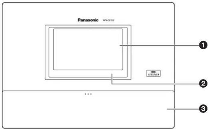
① LCD display
This is a 7-Type color LCD display. It indicates this unit's operational status and details of its operations and settings.
② Touch panel
This is a 7.8-Type touch panel. It is used to operate this unit.
③ Terminal cover
This is where the “Euroblock” (a European-style terminal block) for the audio input/output signals and control input/output signals is housed.
Terminal block
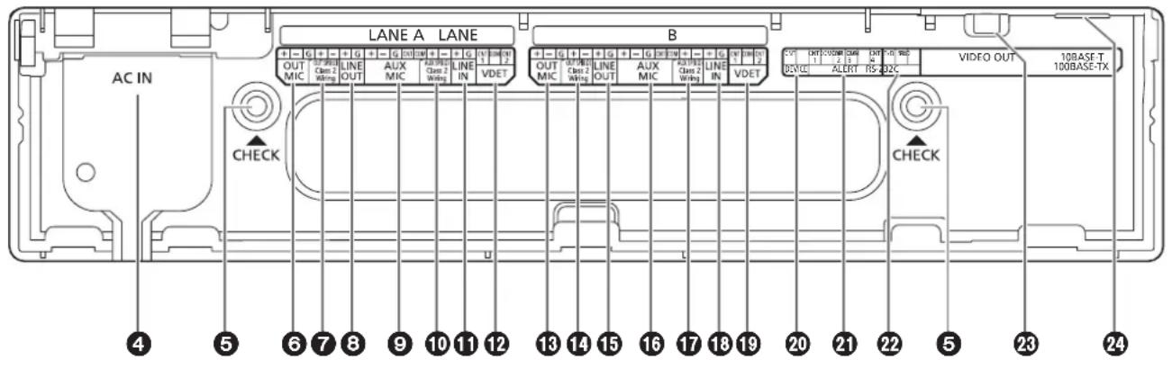
④ Power input terminal [AC IN]
Connect the accessory power cord to this terminal. After connecting it, secure the cord using the power cord clamp. (Refer to p.24 "Securing the power cord".)
⑤ Confirmation window [CHECK]
This window is used for confirmation purposes when this unit is installed.
⑥ Lane A mic input [OUT MIC]
This is connected to the microphone for the order post installed in lane A.
⑦ Lane A speaker output
[OUT SP (8 Ω) Class2 Wiring]
This is connected to the speaker for the order post installed in lane A.
⑧ Lane A line output [LINE OUT]
The same communication that is output from OUT SP of lane A is output.
⑨ Lane A kitchen mic input [AUX MIC]
This is connected to the gooseneck microphone installed in the lane A kitchen.
It is used to speak with the customer who has arrived at the order post for lane A.
⑩ Lane A kitchen speaker output
[AUX SP (8 Ω) Class2 Wiring]
This is connected to the speaker installed in the lane A kitchen.
It is used to speak with the customer who has arrived at the order post for lane A.
⑪ Lane A line input [LINE IN]
External communications can be broadcast simultaneously to all the All-In-One Headsets or Belt Packs and to the lane A kitchen speaker.
⑫ Lane A vehicle detector input [VDET]
This is connected to the vehicle detector installed in lane A.
⑬ Lane B mic input [OUT MIC]
This is connected to the microphone for the order post installed in lane B.
⑭ Lane B speaker output
[OUT SP (8 Ω) Class2 Wiring]
This is connected to the speaker for the order post installed in lane B.
⑮ Lane B line output [LINE OUT]
The same communication that is output from OUT SP of lane B is output.
16 Lane B kitchen mic input [AUX MIC]
This is connected to the gooseneck microphone installed in the lane B kitchen.
It is used to speak with the customer who has arrived at the order post for lane B.
⑰ Lane B kitchen speaker output
[AUX SP (8 Ω) Class2 Wiring]
This is connected to the speaker installed in the lane B kitchen.
It is used to speak with the customer who has arrived at the order post for lane B.
18 Lane B line input [LINE IN]
External communications can be broadcast simultaneously to all the All-In-One Headsets or Belt Packs and to the lane B kitchen speaker.
⑲ Lane B vehicle detector input [VDET]
This is connected to the vehicle detector installed in lane B.
20 External control output [DEVICE]
This external control output is used for alerts.
Using this unit's settings, this connector is controlled in response to the reception of alert signals from the All-In-One Headsets or Belt Packs and to the signals from the alert input.
21 Alert input [ALERT]
This external input connector is used for alerts. It is connected to a sensor or other external device.
22 Serial port [RS-232C]
This port is for controlling the system from a personal computer.
For details, contact the store where you purchased this unit.
23 Video output [VIDEO OUT]
This NTSC type of composite connector is for outputting camera images.
For details, contact the store where you purchased this unit.
24 Network port [10BASE-T/100BASE-TX]
This is connected to a 10BASE-T or 100BASE-TX network, and it connects the Network Camera with the Center Module.
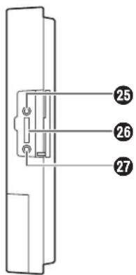
Side panel
25 Reset button
Press this button using a fine-tipped object when this unit is not operating properly to restart this unit.
26 SD card slot
This is where an SD card is inserted.
27 SD card access LED
This indicates the status of the SD card access. While the SD card is being accessed, it blinks in green.
Important
- While the SD card access LED is blinking, do not eject the SD card, disconnect the power plug or press the reset button. Performing any of these actions may destroy the data on the card.
Major operating controls and their functions
Screen
The following four buttons, which are separate from the LCD display buttons, are permanently displayed on the touch panel.
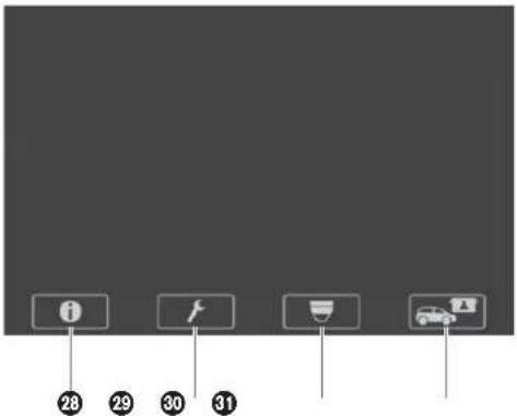
28 Setting Information button
This button is used to display the settings and statuses. (Refer to p.16 "Setting Information screen".)
30 Camera display button
This button is used to display the images of the Panasonic Network Cameras that have been registered. (Refer to p.18 "Camera monitoring screen".)
29 Setting button
This button is used to display the password input screen. After the password has been confirmed, the setting list screen is displayed. (Refer to p.18 "Password input screen".)
31 Quick Operation button
This button is used to display the Quick Operation screen that is used with drive-thru operations. (Refer to p.19 "Quick Operation screen".)
Basic screen
The basic screen that appears on the LCD display is described below.
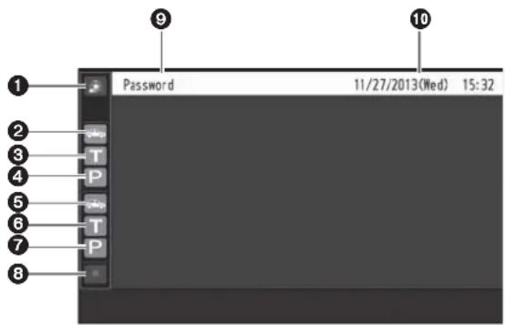
① Security Alert display

When an alert signal has been received from an external device or an All-In-One Headset or Belt Pack, this is displayed in red.
② Vehicle detection display (lane A)

When a vehicle has arrived at the order post for lane A, this is displayed in orange.
While the store personnel are talking to the customer in lane A, this is displayed in orange.
④ Paging display (lane A)

While the store personnel at lane A are talking to one another, this is displayed in orange.
⑤ Vehicle detection display (lane B)

When a vehicle has arrived at the order post for lane B, this is displayed in green.
⑥Talk display (lane B)

While the store personnel are talking to the customer in lane B, this is displayed in green.
⑦ Paging display (lane B)

While the store personnel at lane B are talking to one another, this is displayed in green.
⑧ REC button

When a communication is being recorded after a security alert has occurred, this is displayed in red.
⑨ Title display
The title of the screen currently displayed appears.
⑩ Date & time display
The current date and time are displayed.
“*” appears in front of the time display during daylight savings time (summer time).
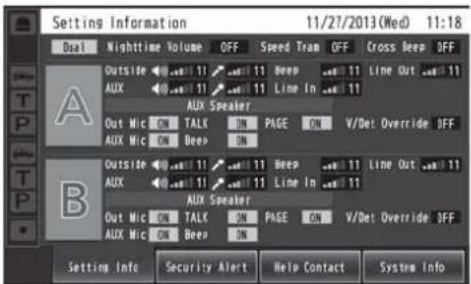
■ Setting Information screen
The Setting Information screen appears when (Setting Information button) on the touch panel is touched. This unit's settings and statuses can be confirmed on this screen.
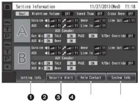
① Setting Info [Setting Info]
When the Setting Info button is touched, the display on the LCD display switches to the setting list screen.
② Security Alert [Security Alert]
When the Security Alert button is touched, the display on the LCD display switches to the Security Alert screen. (P.17)
③ Help Contact [Help Contact]
When the Help Contact button is touched, the display on the LCD display switches to the Help Contact screen. (P.18)
④ System Information [System Info]
When the System Info button is touched, the screen on the LCD display switches to the System Info screen. (P.18)
Setting list screen
The setting list screen is displayed when the unit's power is turned on or when the [Setting Info] button is touched.
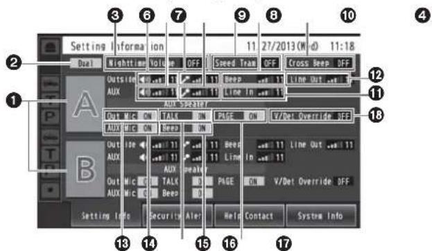
① Lane name display [A] ([B])
The lane name is displayed. The lane setting statuses are displayed to the right of the lane name display. When the WX-CC412 is used, lane B is also displayed underneath lane A.
② Lane mode display [Single/Dual/Tandem]
Lane mode that has been set is displayed. WX-CC411: [Single] is displayed. WX-CC412: [Dual] is displayed when the tandem lane setting is OFF, and [Tandem] is displayed when it is ON.
③ Nighttime Volume display [Nighttime Volume ON/OFF/AUTO]
The setting status of the volume of the order post speaker at night is displayed.
Note
- The "Nighttime Volume" is a function that is used to adjust the volume level of the voice output from the order post speaker.
④ Speed Team display [Speed Team ON/OFF]
The status of the speed team operation is displayed.
Note
- "Speed Team operation" refers to a mode of operation in which, at busy times when there are more vehicles than the lanes can accommodate, normal operation is suspended, the vehicle detectors are shut off, and the store personnel go directly to the customers in their vehicles to take their orders.
⑤ Cross Beep display [Cross Beep ON/OFF]
The Cross Beep status is displayed. This appears only when the WX-CC412 is used.
Note
- "Cross Beep" is a function that sends the beep tone announcing the arrival of customers across the two lanes.
Eδ Lane A order post speaker volume display [Outside]
The volume level of the lane A order post speaker is displayed.
⑦ Lane A kitchen speaker volume display [AUX]
The volume level of the lane A kitchen speaker is displayed.
⑧ Lane A order post microphone volume display [Outside]
The volume level of the lane A order post microphone is displayed.
⑨ Lane A kitchen microphone volume display [AUX]
The volume level of the lane A kitchen microphone is displayed.
⑩ Lane A beep tone volume display [Beep]
The volume level of the lane A beep tone is displayed.
⑪ Lane A line input volume display [Line In]
The volume level of the lane A line input is displayed.
⑫ Lane A line output volume display [Line Out]
The volume level of the lane A line output is displayed.
⑬ Lane A order post microphone ON/OFF display [Out Mic ON/OFF]
The setting that determines whether to output the voice of the lane A order post microphone to the lane A kitchen speaker is displayed.
⑭ Lane A kitchen microphone ON/OFF display [AUX Mic ON/OFF]
The setting that determines whether to output the voice of the lane A kitchen microphone to the lane A kitchen speaker is displayed.
⑮ Lane A talk ON/OFF display [TALK ON/OFF]
The setting that determines whether to output the talk voice to the lane A kitchen speaker is displayed.
Note
- “Talk” refers to communications between the customers and store personnel.
⑯ Lane A beep tone ON/OFF display [Beep ON/OFF]
The setting that determines whether to output the beep tone to the lane A kitchen speaker is displayed.
⑰ Lane A paging ON/OFF display [PAGE ON/OFF]
The lane A paging setting is displayed.
Note
- “Paging” refers to communications among store personnel.
18 Lane A V/Det Override ON/OFF display [V/Det Override ON/OFF]
The status of the lane A V/Det Override is displayed.
Note
- "V/Det Override" is a function that sets the vehicle detectors virtually to ON and keeps both the order post microphone and speaker in the ON setting.
Security Alert screen
The Security Alert screen appears when the [Security Alert] button on the Setting Information screen is touched.
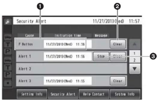
① Cause and Initiation time
The cause of a security alert that has occurred and the initiation time are displayed.
[F Button] : Sent from the store personnel who have All-In-One Headsets or Belt Packs.
[Alert 1 to 4] : Sent from alert input 1 to 4.
② Clear button [Clear]
This is touched to forcibly clear the Security Alert.
③ Stop button [Stop]
This is touched when the Alert Message for the Security Alert is to be stopped.
This appears when “Alert message playback” has been set for operations to be performed when a Security Alert has occurred.
Help Contact screen
The Help Contact screen appears when the [Help Contact] button on the LCD display is touched.
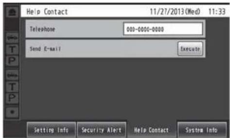
The emergency help contact is displayed on this screen. It can be set on the setting screen. If an email has been set using the browser ahead of time, an email can be sent from this screen.
Note
- It is not possible to display the email send result even when, for instance, an email failed to be sent because the server was down or the wrong email was set. When installing this unit, check that emails can be correctly sent ahead of time.
System Info screen
The System Info screen appears when the [System Info] button on the LCD display is touched.

Network statuses are shown on this screen.
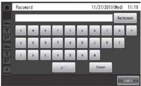
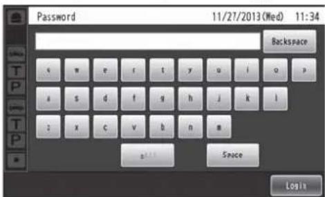
■ Password input screen
The password must be input for verification before operation moves to the setting screen.
The password input screen appears when ⚡ (setting button) on the touch panel is touched. For details on how to input the characters, refer to p.30 "Inputting characters".

Default password: 12345
Important
- Change the password at regular intervals for security purposes.
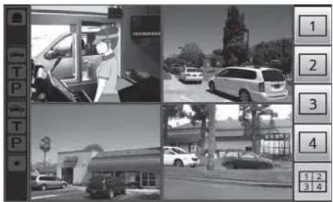
■ Camera monitoring screen
The camera monitoring screen appears on the LCD display when 🚗 (camera display button) on the touch panel is touched.
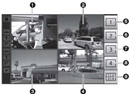
① Camera 1 screen
Images from Network Camera 1 appear on this part of the screen.
② Camera 2 screen
Images from Network Camera 2 appear on this part of the screen.
③ Camera 3 screen
Images from Network Camera 3 appear on this part of the screen.
④ Camera 4 screen
Images from Network Camera 4 appear on this part of the screen.
⑤ Camera 1 full-screen display button
When this button is touched, images from Network Camera 1 are displayed in full-screen mode.
⑥ Camera 2 full-screen display button
When this button is touched, images from Network Camera 2 are displayed in full-screen mode.
⑦ Camera 3 full-screen display button
When this button is touched, images from Network Camera 3 are displayed in full-screen mode.
⑧ Camera 4 full-screen display button
When this button is touched, images from Network Camera 4 are displayed in full-screen mode.
⑨ 4-screen simultaneous display button
When this button is touched, the screen is split into four parts, and the images from Network Cameras 1, 2, 3 and 4 are displayed simultaneously.
Note
- When a camera image is touched while the screen is split into four parts and images are displayed simultaneously, the touched image is displayed in full-screen mode.
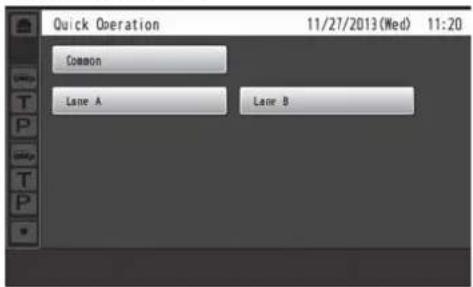
■ Quick Operation screen
The Quick Operation screen appears on the LCD display when 📄 (Quick Operation button) on the touch panel is touched.
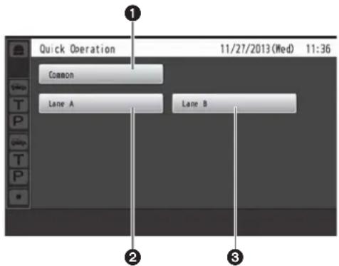
① Common button
This button is used to display the Quick Operation screen that is common to both lanes.
② Lane A button
This button is used to display the Quick Operation screen for lane A.
③ Lane B button
This button is used to display the Quick Operation screen for lane B.
Note
- The lane B button is displayed only when the WX-CC412 is used.
Devices related to the wireless intercom system are listed below.
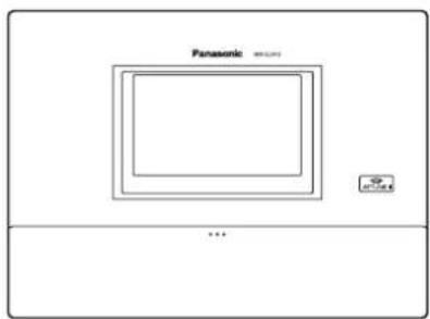
◆ Center Module
WX-CC411/WX-CC412
◆ Belt Pack
WX-CT420

natural_image
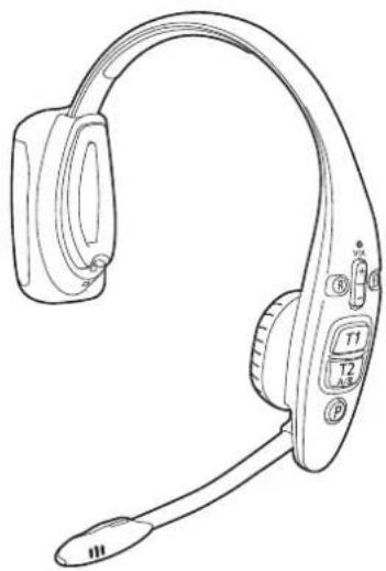
Line drawing of a rectangular electronic device with buttons and ports (no text or symbols)◆ All-In-One Headset
WX-CH450
natural_image
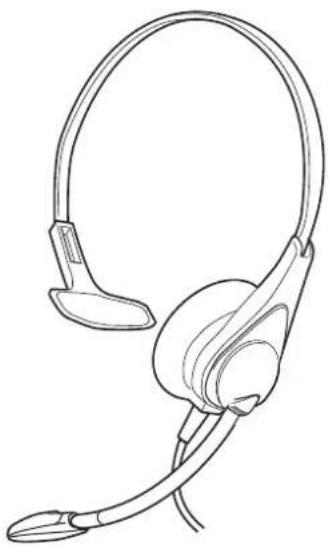
Line drawing of a pair of headphones with earbuds and connector ports (no text or symbols)◆ Headset
WX-CH427
natural_image
Line drawing of a headset with ear and antenna (no text or symbols)◆ Battery
WX-B3030

natural_image
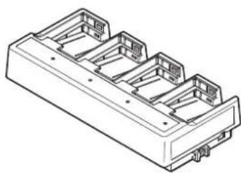
Simple line drawing of a rectangular electronic device with a slot (no text or symbols)◆ Battery Charger
WX-Z3040A
natural_image
Isometric line drawing of a multi-chamber electronic component housing (no text or symbols)◆ Wireless Repeater
WX-CR470
■ Deciding on where to install the Center Module
Select a wall on which to mount this unit, drill a hole in it to pass the wires through, and decide where the four screws are to be positioned, as shown below.
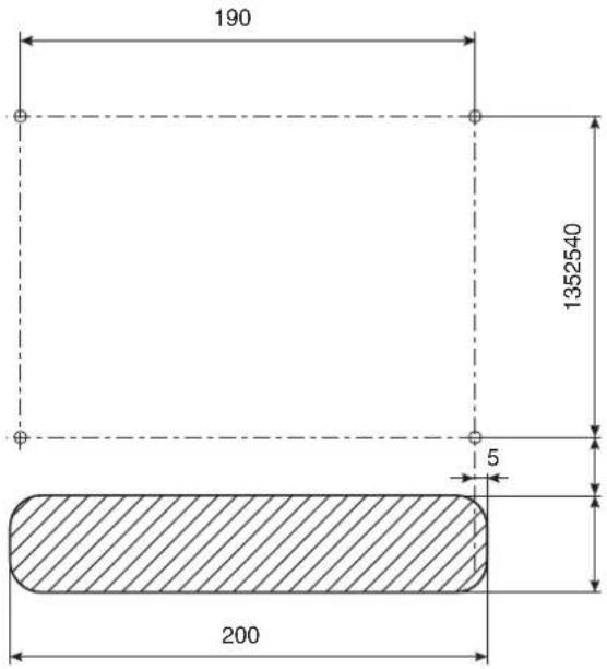
Important
- Ensure that the installation surface has the pull-out strength below.
Installation
1 Mount this unit using the accessory wall mounting bracket and 4 screws (4.1 mm × 25 mm {5/32 inches × 63/64 inches}).
[Minimum pull-out strength: 780 N {80 kgf}]
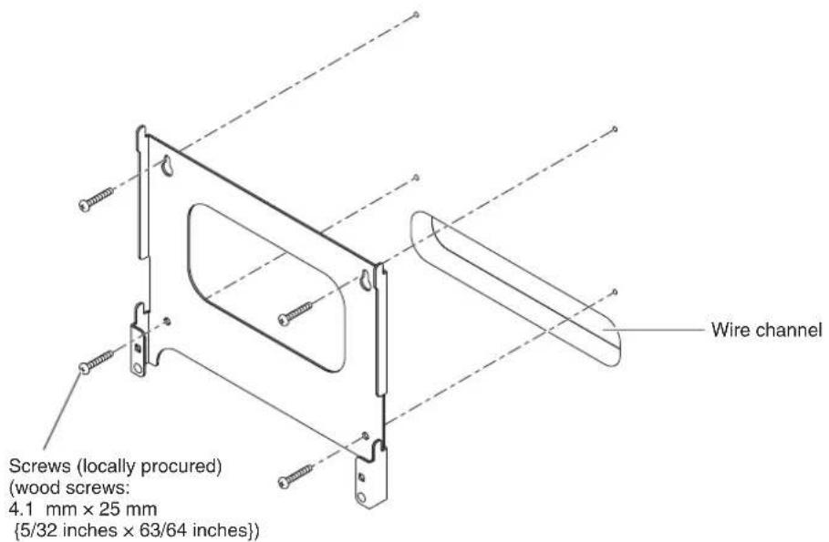
2 Mount this unit onto the four hooks of the wall mounting bracket.
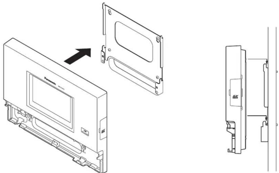
3 Look at the confirmation window (which is marked "CHECK"), and confirm that this unit fits properly into place.
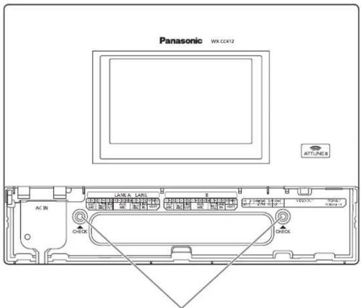
Check that the "O" marks of the wall mounting bracket are visible. If they are not visible, this means that this unit has not been installed properly.
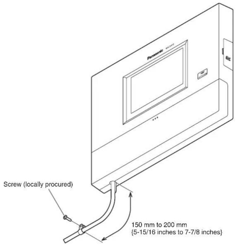
4 Use the accessory clamp to secure the power cord to the wall and attach the clamp using a screw (4.1 mm × 25 mm {5/32 inches × 63/64 inches}). [Minimum pull-out strength: 780 N {80 kgf}]
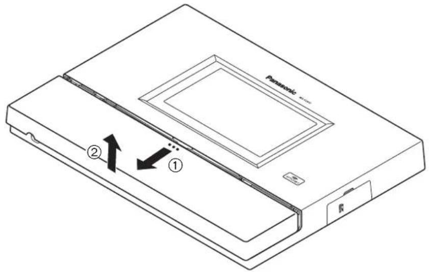
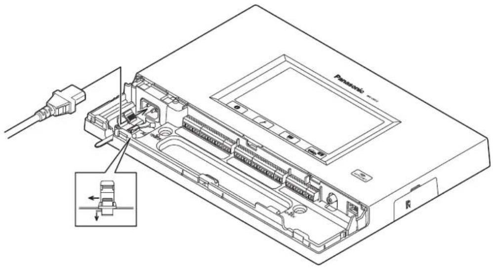
■ Opening the connector cover
Press on the area indicated by ① and slide the connector cover down, and pull the bottom part of the cover toward you as indicated by ②.
■ Securing the power cord
1 Insert the accessory power cord clamp into this unit.
2 Before proceeding any further, push down the position of the power cord clamp inserted into this unit, as shown in the figure below. Insert the power cord plug into the power socket of this unit, adjust the position of the power cord clamp, and secure the power cord.
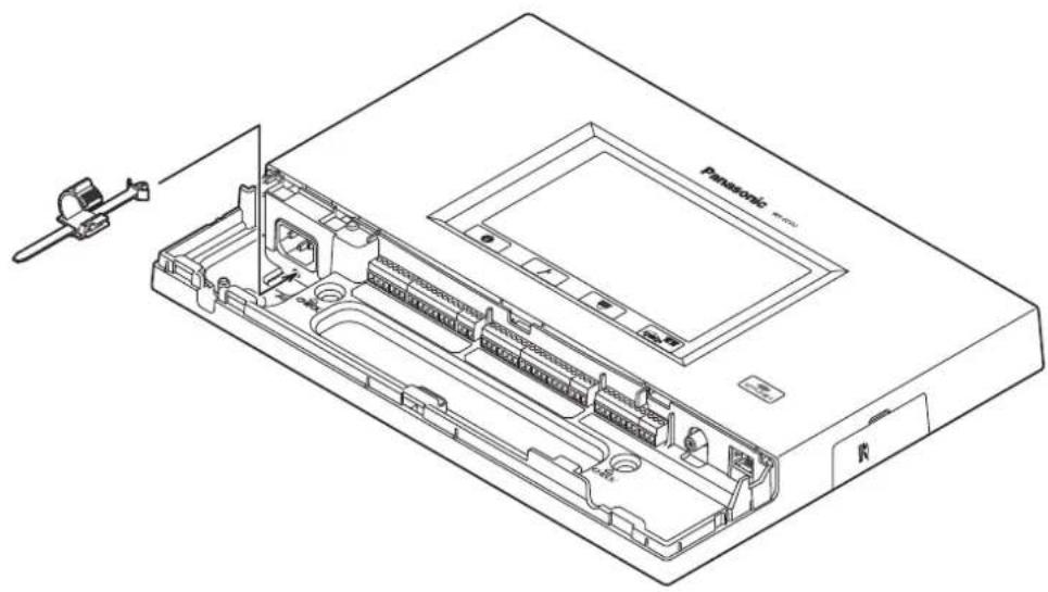
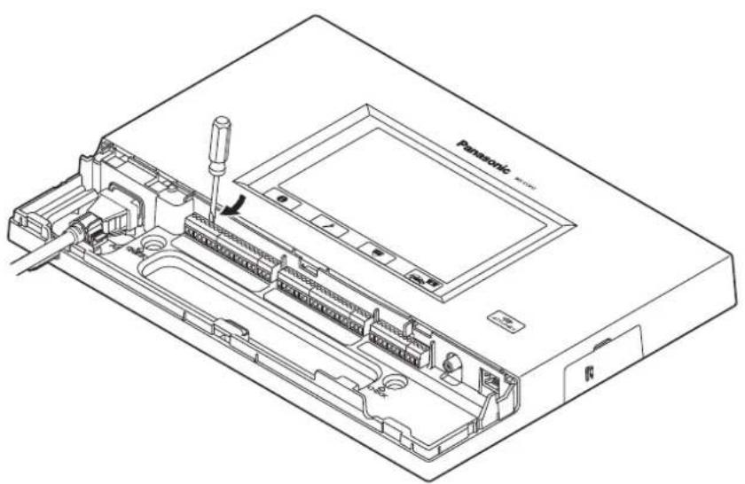
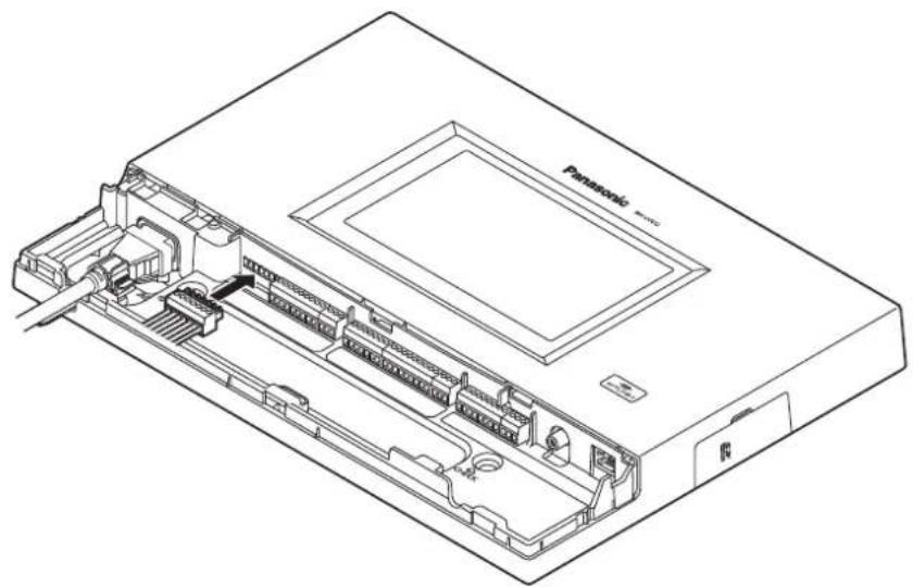
■ Wiring the Euroblock connector
1 A detachable Euroblock connector is provided for this unit's connectors. As shown in the figure below, insert a slot-head screwdriver into the gap, and remove the Euroblock connector from this unit.
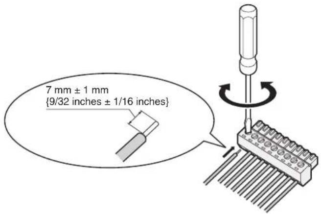
2 Connect the wires to the Euroblock connector. Using a slot-head screwdriver, loosen the Euroblock connector screws in turn, peel off the insulating material around each of the wires, twist the conductors firmly, insert the ends of the conductors into the Euroblock connector, and tighten the Euroblock connector screws.
Note
Shaping the cables
- Recommended wires: AWG28 to 16 (Do not use soldered wires.)
• Length of insulating material to be peeled off: 7 mm ± 1 mm {9/32 inches ± 1/16 inches} - Screw diameter: 2 mm {3/32 inches}
- Check that the wires have been connected securely.
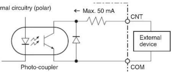
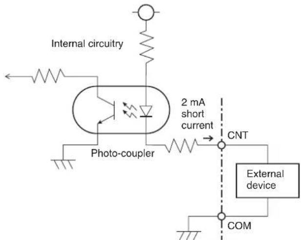
Electrical specifications of connectors
- DEVICE CNT and DEVICE COM connectors Connect an external device between the CNT and COM connectors. These connectors are isolated from the internal circuitry using a photo-coupler.
Electrical specifications: 30 V control voltage, 50 mA control current
- ALERT CNT and ALERT COM connectors Connect an external device between the CNT and COM connectors. These connectors operate by a "make" action. The COM connector is connected to the GND inside this unit.
Electrical specifications: DC 5 V open voltage, 2 mA short current
3 Install the Euroblock connector, to which the wires have been connected, in this unit.
natural_image
Technical line drawing of a Panasonic electronic device showing internal components and ports (no text or symbols)Note
- Insert the Euroblock connector firmly into this unit.
■ Attaching the connector cover
Slide the connector cover from below, and attach it to this unit.
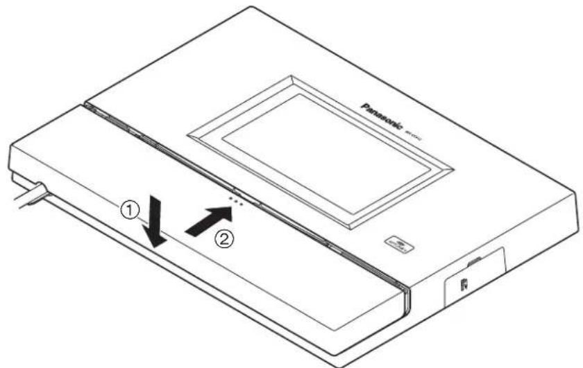
Note
- Attach the connector cover securely to this unit.
■ Examples of connections
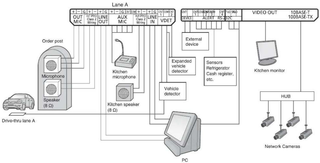
flowchart
graph TD
    A["Drive-thru lane A"] --> B["Order post"]
    B --> C["Microphone"]
    C --> D["Speaker (8 Ω)"]
    D --> E["Line OUT"]
    E --> F["AUX MIC"]
    E --> G["AUX SPIR Class 2 Wiring"]
    E --> H["LINE IN"]
    H --> I["VDET"]
    I --> J["PC"]
    J --> K["Vehicle detector"]
    K --> L["Kitchen microphone"]
    K --> M["Kitchen speaker (8 Ω)"]
    L --> N["Line OUT"]
    M --> O["Line OUT"]
    N --> P["OUT MIC"]
    O --> Q["OUT SPIR Class 2 Wiring"]
    P --> R["LIVE OUT"]
    Q --> S["LIVE OUT"]
    R --> T["LINE OUT"]
    S --> U["LIVE OUT"]
    T --> V["OUT MIC"]
    U --> W["OUT SPIR Class 2 Wiring"]
    V --> X["LIVE OUT"]
    W --> Y["LIVE OUT"]
    X --> Z["LIVE OUT"]
    Y --> AA["LIVE OUT"]
    Z --> AB["LIVE OUT"]
    AA --> AC["LIVE OUT"]
    AB --> AD["LIVE OUT"]
    AC --> AE["LIVE OUT"]
    AD --> AF["LIVE OUT"]
    AE --> AG["LIVE OUT"]
    AF --> AH["LIVE OUT"]
    AG --> AI["LIVE OUT"]
    AH --> AJ["LIVE OUT"]
    AI --> AK["LIVE OUT"]
    AJ --> AL["LIVE OUT"]
    AK --> AM["LIVE OUT"]
    AL --> AN["LIVE OUT"]
    AM --> AO["LIVE OUT"]
    AN --> AP["LIVE OUT"]
    AO --> AQ["LIVE OUT"]
    AP --> AR["LIVE OUT"]
    AQ --> AS["LIVE OUT"]
    AR --> AT["LIVE OUT"]
    AS --> AU["LIVE OUT"]
    AT --> AV["LIVE OUT"]
    AU --> AW["LIVE OUT"]
    AV --> AX["LIVE OUT"]
    AW --> AY["LIVE OUT"]
    AX --> AZ["LIVE OUT"]
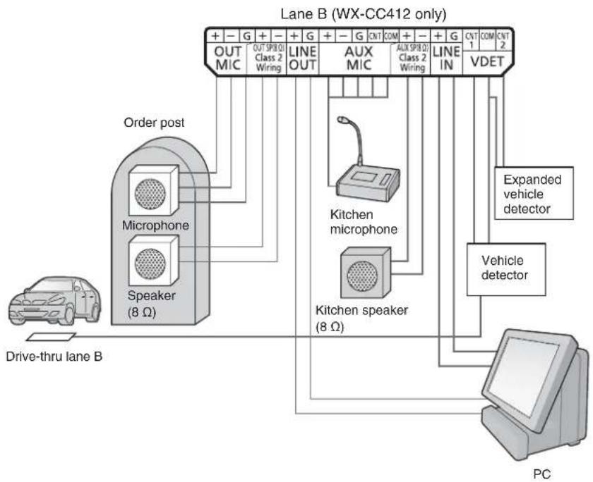
flowchart
graph TD
    A["Drive-thru lane B"] --> B["Speaker (8 Ω)"]
    B --> C["Microphone"]
    C --> D["Order post"]
    D --> E["OUT MIC"]
    D --> F["OUT SPIR 0 Class 2 Wiring"]
    D --> G["LINE OUT"]
    G --> H["AUX MIC"]
    G --> I["Line IN"]
    H --> J["VDET"]
    I --> J
    K["PC"] --> L["Vehicle detector"]
    M["Expanded vehicle detector"] --> L
    N["Kitchen microphone"] --> O["Kitchen speaker (8 Ω)"]
    P["Line OUT"] --> Q["Line IN"]
    R["Line OUT"] --> S["AUX SPIR 0 Class 2 Wiring"]
    T["Line OUT"] --> U["VDET"]
■ Basic screen operations
This section describes basic screen operations.
For details on how to operate the unit and select its settings, refer to the "Operating Instructions
![Store Settings 11/27/2013(Med) 11:37 Nighttime Volume Store Hours Tandem Lane Store Hours(Closed Message) 11/27/2013(Med) 11:44 OFF [001]Greeter 01 [002]Greeter 03 [003]Greeter 03 [004]Greeter 04 [005]Greeter 05 [006]Greeter 06 [007]Greeter 07 [008]Greeter 08 1/4 3](/content/2026/03/529007/images/3e5766553811acbf1891076389d00e4ce3a083ff5cc21ce3af928f1b98ef4c4e.jpg)
① Return button
This button is used to return to the previous screen.
② Item selector buttons
Operation moves to the screen corresponding to the button that has been touched. On the setting screen, one of the buttons is selected (indicated in orange).
The buttons have different names, depending on the situation.
③ Page selector buttons
These buttons are used to select the page when the screen extends over a multiple number of pages. When the ▼ button is touched, the next page screen is displayed, and when the ▲ button is touched, the previous page screen is displayed.
Note
- The LCD display is easily scratched, so always perform the operations involving this display using one finger.
- Do not use a ballpoint pen or other hard-tipped or sharp object, including fingernails, to perform touch panel operations.
- Do not press on the LCD display with too much force.
- Do not use any of the LCD protective films available on the market. (The touch panel may not operate properly.)
- The inside of the LCD display may become cloudy or condensation (droplets of water) may form and the display may not operate properly when the temperature changes suddenly, such as immediately after air-conditioning or heating has been turned on. If this occurs, leave this unit for about one to two hours before attempting to use it again.
■ Entering the settings
On a screen with multiple setting items, touch the [Set] button to confirm a setting.
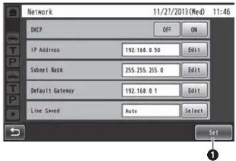
① Set button
This button confirms all multiple settings displayed on the screen together.
■ Inputting characters
Use the keys on the keyboard to input the characters when a password or an address is to be input.
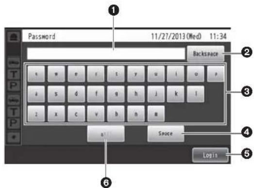
① Input character display area
The characters that have been input are displayed.
② Backspace button
Touch this button to delete the last character of the characters shown in the input character display area.
③ Character input buttons
The character on the button that is touched is input.
④ Space button
Touch this button to input a space.
⑤ Set/Enter button [Enter/Login]
Touch this button to enter the character string that has been input.
⑥ Character type selector button
Touch this button to change the type of characters that are to be input.
■ Inputting the date and time
Input the date and time—the time may involve using Daylight Saving Time.
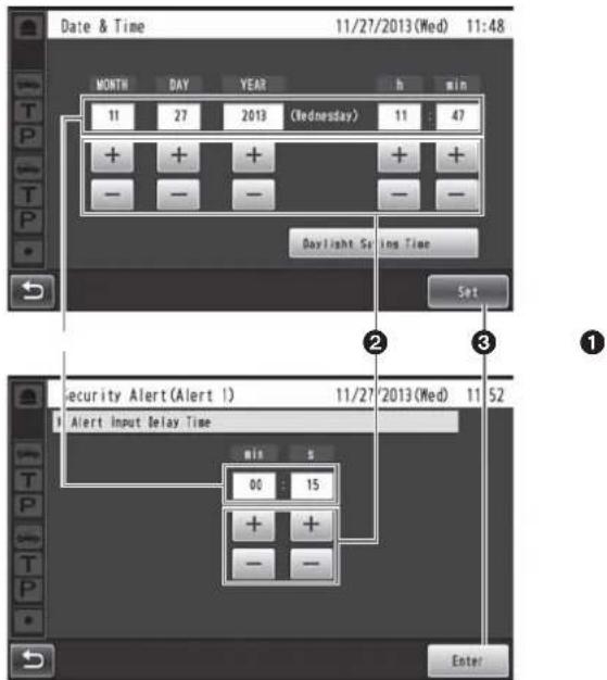
① Setting value display area
The current setting values are displayed.
② + and - buttons
Adjust the settings by touching the + and - buttons.
③ Set/Enter button [Set/Enter]
Touch this button to enter the time that has been set.
■ Adjusting the volume level
Adjust the volume level.
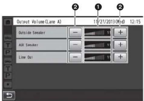
① Volume level display area
The current volume levels are displayed.
② + and - buttons
Adjust the levels by touching the + and - buttons. Changes in the volume level take place in real time.
■ Basic operations
TALK: Talking with the customers
This function enables two-way conversations between the store personnel who are wearing All-In-One Headsets or Belt Packs and the customer at the order post. For further details on conversation methods, refer to the Operating Instructions for the Belt Pack (WX-CT420) or All-In-One Headset (WX-CH450).
PAGE: Talking with other store personnel
Store personnel who are wearing All-In-One Headsets or Belt Packs can talk to one another without being heard by customers.
For further details on paging methods, refer to the Operating Instructions for the Belt Pack (WX-CT420) or All-In-One Headset (WX-CH450).
Dual drive-thru lane changeover (WX-CC412 only)
In the case of a dual drive-thru, it is possible to talk or page by selecting lane A or lane B.
For details on how to perform lane changeover operation, refer to the Operating Instructions for the Belt Pack (WX-CT420) or All-In-One Headset (WX-CH450).
ID Registration
- To talk or page using an All-In-One Headset or Belt Pack, its ID must be registered.
- For ID registration, set the Center Module to ID registration mode, and proceed with the registration by operating the All-In-One Headset or Belt Pack concerned.
The ID registration procedure is described below based on an example involving an All-In-One Headset or Belt Pack operation.
1 Touch (setting button) on the touch panel.
• The password input screen appears.
2 Input the password, and touch the [Login] button.
Default password: 12345
Important
- Change the password at regular intervals for security purposes.
• The setting menu is displayed.
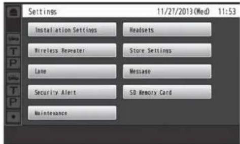
3 Touch [Headsets] button, and then the [ID Registration] button.
• The ID registration screen appears.
![ID Registration 11/27/2013 (Wed) 11:58 Push "Start" button to begin ID registration mod. Start Stop [Registered Headsets] 01.02.03.04.05.06.](/content/2026/03/529007/images/7aeec7d0984232253f448370178b2c1dfa0de66ba6aeda4e2774c238d988b341.jpg)
Note
- The registered All-In-One Headset or Belt Pack numbers are displayed in the [Registered Headsets] area. When ID registration is completed successfully, the ID of the newly registered All-In-One Headset or Belt Pack is added.
4 Touch the [Start] button.
- The following pop-up screen is displayed. You cannot perform other operations during ID registration. To continue ID registration, touch the [YES] button. To stop ID registration, touch the [NO] button.
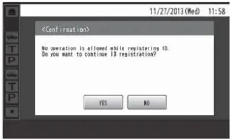
- Touch the [YES] button to start ID registration mode.
![ID Registration 11/27/2013 (Wed) 11:58 Execute ID resistration by operating a headset button. ID Registration Mode... Push "Stop" button to exit ID Registration mode. Start Stop [Registered Headsets] 01.02.03.04.05.06.](/content/2026/03/529007/images/2068400a3f9a4a3d684edd5b2bfeb5f897f1abaf8f9328b095f3146973ea520a.jpg)
The number of the All-In-One Headset or Belt Pack that has been registered is displayed.
5 Press the [POWER] button while holding down the [T1] button and [T2] button of the All-In-One Headset or Belt Pack.
- The All-In-One Headset or Belt Pack starts up in ID registration mode. The "ID Registration Mode" voice prompt will be heard from the earphone, and the power indicator will blink orange. In ID registration mode, the buttons and indicators have different functions from those at normal startup.
6 Press the [T1] button on the All-In-One Headset or Belt Pack.
- The All-In-One Headset or Belt Pack searches for a Center Module that is in ID registration mode. The "Connecting center module A" voice prompt will be heard from the earphone, and the lane indicator will blink orange.
In the case of the WX-CC412, after lane A registration, the "Connecting center module B" voice prompt will be heard, and the lane indicator will blink green.
- When ID registration has been completed successfully, the "Registration complete" voice prompt will be heard from the earphone, and then a voice prompt for the number of the registered All-In-One Headset or Belt Pack will be heard. The power indicator and the lane indicator now stop blinking, and light up.
After registrating all of the headset IDs, touch the [Stop] button on the ID registration screen.
ID registration mode for the Center Module is exited. The power indicator of the All-In-One Headset or Belt Pack changes from orange to green.
Important
- When registering the IDs of a multiple number of All-In-One Headsets or Belt Packs, register the ID of each unit in sequence. If an attempt is made to register the IDs of multiple units at the same time, the IDs may not be registered correctly.
- During the ID registration process, do not turn off the power of the All-In-One Headsets or Belt Packs or remove their batteries. Otherwise, their IDs may not be registered correctly. If the registration is not proceeding smoothly, touch the [Stop] button on the Center Module, exit ID registration mode, and then try again.
- When ID registration fails, a "BUU-UU-UU" warning sounds in the All-In-One Headset or Belt Pack concerned, and then the "Failed" voice prompt is heard. If an ID registration has failed, the ID of the All-In-One Headset or Belt Pack will not be registered in the Center Module, and the power indicator of the All-In-One Headset or Belt Pack concerned will blink in red.
- The IDs of up to 32 All-In-One Headsets or Belt Packs can be registered in one Center Module. If an attempt is made to register IDs for more than 32 units, the IDs of the headsets not used for the longest time will be automatically deleted, and then the IDs of the new units will be registered.
- It is not possible to register the ID of a wireless repeater while ID registration mode of the All-In-One Headsets or Belt Packs is active.
■ Convenient Functions (Other Functions)
Auto-TALK-Lock
This function enables the All-In-One Headset or Belt Pack of pre-determined store personnel to automatically enter talk mode when a customer approaches the order post. (Talk-Lock mode)
For details on how to set Auto-Talk-Lock mode, refer to the Operating Instructions for the Belt Pack (WX-CT420) or All-In-One Headset (WX-CH450).
Manager mode
One of all the All-In-One Headsets or Belt Packs in a lane can be set to manager mode.
The All-In-One Headset or Belt Pack in manager mode has a higher priority than the other All-In-One Headsets or Belt Packs, and can monopolize one of the four communication channels.
This means that the manager can talk or page at any time. For details on how to set manager mode, refer to the Operating Instructions for the Belt Pack (WX-CT420) or All-In-One Headset (WX-CH450).
Speed Team
“Speed Team operation” refers to a mode of operation in which, at busy times when there are more vehicles than the lanes can accommodate, normal operation is suspended, the vehicle detectors are shut off, and the store personnel go directly to the customers in their vehicles to take their orders.
1 Touch Quick Operation button) on the touch panel, and then the [Common] button.
2 Touch the [ON] button for [Speed Team] to enable Speed Team operation.
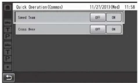
- In the All-In-One Headsets or Belt Packs, the "SPEED TEAM ON" voice prompt is heard from the earphones.
Note
- In Speed Team mode, the "SPEED TEAM ON" voice prompt will be heard every 5 minutes from the earphone of the All-In-One Headsets or Belt Packs.
3 When the [P] button of the All-In-One Headset or Belt Pack is pressed, conversation becomes possible in page lock mode.
- Even if the [P] button is set to Press-to-Page, the button will still operate in page lock.
- For further details on paging methods, refer to the Operating Instructions for the Belt Pack (WX-CT420) or All-In-One Headset (WX-CH450).
4 To release Speed Team operation, touch the [OFF] button for [Speed Team] on the screen in step 2.
- In the All-In-One Headsets or Belt Packs, the "SPEED TEAM OFF" voice prompt is heard from the earphones, and normal operation is restored.
Note
- In Speed Team mode, it is not possible to talk with customers at the order posts.
- When talking is attempted from an All-In-One Headset or Belt Pack, the "Operation not allowed" voice prompt is heard from the earphone.
Cross Beep (WX-CC412 only)
“Cross Beep” is a function that enables a beep tone to be heard from the All-In-One Headsets or Belt Packs when a customer approaches the order post of the other lane.
1 Touch (Quick Operation button) on the touch panel, and then touch the [Common] button.
2 Touch the [ON] button for [Cross Beep] to enable Cross Beep operation.
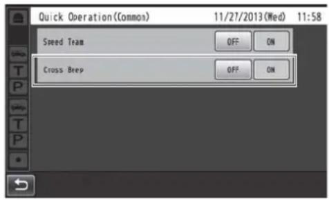
- To release Cross Beep, touch the [OFF] button.
OFF:
If lane A has been selected, beep tone A will be heard when a vehicle in lane A is detected. However, beep tone B will not be heard even when a vehicle in lane B has been detected.
ON:
If lane A has been selected, beep tone A will be heard when a vehicle in lane A is detected. Furthermore, beep tone B is heard at a low volume level even when a vehicle in lane B has been detected. When vehicles have been detected in both lanes, beep tone A and beep tone B, which are heard at a low volume level, will be heard alternately.
| Cross Beep | Vehicle detector All-In-One Headset or Belt Pack | |||
| Lane A is ON | Lane B is ON | A | B | |
| OFF | ○ | - | Beep A | - |
| - | ○ | - | Beep B | |
| ○ | ○ | Beep A Beep B | ||
| ON | ○ | - | Beep A Low level | Beep A |
| - | ○ | Low level Beep B | Beep B | |
| ○ | ○ | Beep A + Low level Beep B | Beep B + Low level Beep A | |
V/Det Override
“V/Det Override” is a function that sets the vehicle detectors virtually to ON and keeps both the order post microphone and speaker in the ON setting.
1 Touch Quick Operation button) on the touch panel, and then touch the [Lane] button.
2 Touch the [ON] button for [V/Det Override] to enable this function.
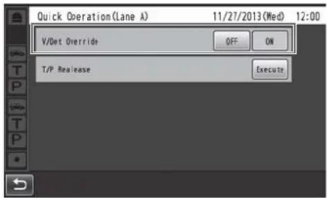
• To release V/Det Override, touch the [OFF] button.
OFF:
When the vehicle detector detects a vehicle at the order post, a beep tone is heard from the earphone.
When the Talk button on an All-In-One Headset or Belt Pack is pressed, the order post's speaker and microphone are turned on.
When the vehicle drives off, vehicle detection is turned off.
The OFF setting and Auto-Talk-Lock mode can now be established.
ON:
When [V/Det Override] is set to ON, the order post's microphone is turned on permanently and talking is enabled even when the vehicle detector is not ON. (Sound from the order post's microphone can be forcibly heard.)
-Note
- When Speed Team is enabled, the setting for V/Det Override is automatically turned OFF.
- In Speed Team mode, you cannot change the setting for V/Det Override.
Talk/page release
The talk (or page) status of an All-In-One Headset or Belt Pack is forcibly released.
1 Touch Quick Operation button) on the touch panel, and then touch the [Lane] button.
2 Touch the [Execute] button for [T/P Release].
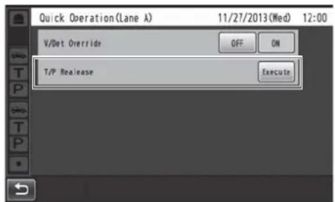
- Communication is forcibly terminated.
Note
- The talk (or page) status of the All-In-One Headset or Belt Pack in manager mode is not released.
Check the following before requesting repair.
Consult your sales shop if these measures do not resolve a problem, if symptoms not listed here occur, or if you have a question related to engineering.
| Symptom Cause/solution Reference pages | ||
| No communication between the order post, Belt Packs and All-In-One Headsets is possible. | Is the power cord connected securely to the AC input terminal of this unit and to the power outlet?→ Check whether it is connected. | P.24 |
| Paging between the store personnel is possible, but talking with the customers using the order post is not possible. | Have the microphone input and speaker output of the order post been connected properly?→ Check whether it is connected properly. | P.25 |
| An echo is heard from the earphone of the headset when an individual is talking into the headset microphone. | The speaker and microphone for the order post may not have been installed correctly.→ Check that the speaker and microphone are placed at a sufficient distance from each other, and anchor them securely so that any vibrations are absorbed. | WX-CS460OperatingInstructions |
| The input and output audio levels may have been set too high.→ Lower the audio input and output levels (OUT MIC/OUT SP) for the order post to the appropriate level. (Feedback noise can be prevented by selecting a setting that lowers the audio input level.) | OperatingInstructions | |
| The echo canceller is off or its level is low.→ Set the echo canceller to the appropriate level. (The default setting is “MID”.) | OperatingInstructions | |
| A lot of noise is heard from order post. | DNR is OFF or its level may be low.→ Set the DNR to the appropriate level. (The default setting is “MID”.) | OperatingInstructions |
| There is no reaction even when the buttons on the touch panel are touched. | Is the touch panel dirty?→ Clean the touch panel.If there is no improvement even after it has been cleaned, adjust the touch panel. | P.10 |
| When one of the buttons on the touch panel has been touched, another button reacts instead. | The touch panel must be adjusted.→ Adjust the touch panel. | OperatingInstructions |
| Communication breaks up or it is hardly possible to hear what is being said. | Are the All-In-One Headsets or Belt Packs too far away from the Center Module, or are there any obstructions such as concrete walls or metal devices between the Center Module and the All-In-One Headsets or Belt Packs?→ Contact the store where you purchased this unit, and move this unit to a location where there are no obstructions around it. | — |
| No communication with the cameras is possible. | Have the cameras been registered in the Center Module?→ No communication with the cameras is possible if the cameras have not been registered. Register the cameras that are to be connected. | OperatingInstructions |
| Nothing happens even when operations are performed correctly; or the operations are performing incorrectly. | This unit may not be working properly.→ Press the reset button on the side panel of this unit using a fine-tipped object. (The settings, etc. will not be cleared.) | P.13 |
General
| Operating frequency 1921.536 MHz to 1928.448 MHz | ||
| POWER | Power source AC 100 V to 120 V 50 Hz/60 Hz | |
| Connector Universal Type with an 3 pins AC Inlet | ||
| Power consumption 17 W | ||
| Operating temperature range -10 | °C to +50 °C {14 °F to 122 °F} | |
| Operating humidity range 20 | % to 90 % (no condensation) | |
| Dimensions | 375 mm (W) × 275 mm (H) × 50 mm (D){14-49/64 inches (W) × 10-53/64 inches (H) × 1-31/32 inches (D)} | |
| Mass Approx 1.9 kg {4.2 lbs.} (Excluding the wall mounting bracket) | ||
User Interface
| LCD display | Type 7 Type | |
| Effective pixels WVGA: 800 (H) × 480 (V) | ||
| Back light LED | ||
| Touch panel | Type 7.8 Type | |
| Technology Resistive type | ||
Audio & Video Interface
| General | Number of channels | 1 (WX-CC411)2 (WX-CC412) |
| Frequency characteristic 300 Hz to 3 kHz | ||
| OUT MIC | Technology Electric balanced | |
| Connector Euroblock connector (HOT/COLD/GND) | ||
| Input impedance | 1.5 kΩ | |
| Rated input | -70 dBV | |
| Maximum input | -38 dBV | |
| OUT SP | Technology Balanced | |
| Connector Euroblock connector | ||
| Rated output for amplifier | 2 W | |
| Conformed load impedance | 8 Ω | |
| AUX MIC | Technology Electric balanced | |
| Connector Euroblock connector (HOT/COLD/GND/PTT/COM) | ||
| Input impedance | 3 kΩ | |
| Rated input | -67 dBV | |
| Maximum input | -44 dBV | |
| Control signal | PTT, Make (No voltage) when talking | |
| AUX SP | Technology Balanced | |
| Connector Euroblock connector | ||
| Rated output for amplifier | 2 W | |
| Conformed load impedance | 8 Ω | |
| LINE IN | Technology Unbalanced, Mono | |
| Connector Euroblock connector | ||
| Rated input -10 dBV | ||
| Maximum input +6 dBV | ||
| LINE OUT | Technology Unbalanced, Mono | |
| Connector Euroblock connector | ||
| Rated output -14 dBV | ||
| Maximum output +6 dBV | ||
Device Interface
| AUX MIC CNT, COM(INPUT) | Number of channels | 1 (WX-CC411)2 (WX-CC412) |
| Technology Photo-coupler | ||
| Open voltage 5 V | ||
| Short current 2 mA | ||
| Connector Euroblock connector | ||
| VDET CNT, COM(INPUT) | Number of channels | 2 (WX-CC411)4 (WX-CC412) |
| Technology Photo-coupler | ||
| Open voltage 5 V | ||
| Short current 2 mA | ||
| Connector Euroblock connector | ||
| ALERT CNT, COM(INPUT) | Number of channels 4 | |
| Technology Photo-coupler | ||
| Open voltage 5 V | ||
| Short current 2 mA | ||
| Connector Euroblock connector | ||
| DEVICE CNT, COM(OUTPUT) | Number of channels 1 | |
| Technology Photo-coupler | ||
| Control voltage DC 30 V | ||
| Control current MAX 50 mA | ||
| Connector Euroblock connector | ||
| RS-232C TxD, RxD, SG | Communication system Asynchronous (full duplex) | |
| Baud rate | 19200 bps | |
| SD card Corresponding card | SD card, SDHC cardNote: miniSD card and MicroSD card are not applicable. | |
| 10BASE-T,100BASE-TX(Network) | Type | 10/100BASE-TX (Full/Half, Auto/Man) |
| Connector RJ-45 | ||
| Supported protocols | IPv4: TCP/IP, HTTP, HTTPS, DHCP, DNS, SMTP, NTP, UPnP, POP | |
| VIDEO OUT | Type | NTSC |
| Output signals | Composite | |
| Connector RCA pin jack | ||
This unit contains thttpd, NetBSD, OpenSSL Project, Arcfour and MD5 message-digest algorithm software licensed by third parties, and use of this software has been granted under the conditions stated below.
LICENSE ISSUES
This product uses some parts of thttpd, NetBSD, OpenSSL Project, Arcfour, MD5 message-digest algorithm.
The use of parts described above are licensed under the conditions below.
«thttpd»
Copyright 1995,1998,1999, 2000 by Jef Poskanzer jef@acme.com. All rights reserved.
Redistribution and use in source and binary forms, with or without modification, are permitted provided that the following conditions are met:
- Redistributions of source code must retain the above copyright notice, this list of conditions and the following disclaimer.
- Redistributions in binary form must reproduce the above copyright notice, this list of conditions and the following disclaimer in the documentation and/or other materials provided with the distribution.
THIS SOFTWARE IS PROVIDED BY THE AUTHOR AND CONTRIBUTORS "AS IS" AND ANY EXPRESS OR IMPLIED WARRANTIES, INCLUDING, BUT NOT LIMITED TO, THE IMPLIED WARRANTIES OF MERCHANTABILITY AND FITNESS FOR A PARTICULAR PURPOSE ARE DISCLAIMED. IN NO EVENT SHALL THE AUTHOR OR CONTRIBUTORS BE LIABLE FOR ANY DIRECT, INDIRECT, INCIDENTAL, SPECIAL, EXEMPLARY, OR CONSEQUENTIAL DAMAGES (INCLUDING, BUT NOT LIMITED TO, PROCUREMENT OF SUBSTITUTE GOODS OR SERVICES; LOSS OF USE, DATA, OR PROFITS; OR BUSINESS INTERRUPTION)
HOWEVER CAUSED AND ON ANY THEORY OF LIABILITY, WHETHER IN CONTRACT, STRICT LIABILITY, OR TORT (INCLUDING NEGLIGENCE OR OTHERWISE) ARISING IN ANY WAY OUT OF THE USE OF THIS SOFTWARE, EVEN IF ADVISED OF THE POSSIBILITY OF SUCH DAMAGE.
«NetBSD»
Copyright (c) 1983, 1990, 1993 The Regents of the University of California. All rights reserved.
(c) UNIX System Laboratories, Inc.
All or some portions of this file are derived from material licensed to the University of California by American Telephone and Telegraph Co. or Unix System Laboratories, Inc. and are reproduced herein with the permission of UNIX System Laboratories, Inc.
Redistribution and use in source and binary forms, with or without modification, are permitted provided that the following conditions are met:
- Redistributions of source code must retain the above copyright notice, this list of conditions and the following disclaimer.
- Redistributions in binary form must reproduce the above copyright notice, this list of conditions and the following disclaimer in the documentation and/or other materials provided with the distribution.
- All advertising materials mentioning features or use of this software must display the following acknowledgement: This product includes software developed by the University of California, Berkeley and its contributors.
- Neither the name of the University nor the names of its contributors may be used to endorse or promote products derived from this software without specific prior written permission.
THIS SOFTWARE IS PROVIDED BY THE REGENTS AND CONTRIBUTORS "AS IS" AND ANY EXPRESS OR IMPLIED WARRANTIES, INCLUDING, BUT NOT LIMITED TO, THE IMPLIED WARRANTIES OF MERCHANTABILITY AND FITNESS FOR A PARTICULAR PURPOSE ARE DISCLAIMED. IN NO EVENT SHALL THE REGENTS OR CONTRIBUTORS BE LIABLE FOR ANY DIRECT, INDIRECT, INCIDENTAL, SPECIAL, EXEMPLARY, OR CONSEQUENTIAL DAMAGES (INCLUDING, BUT NOT LIMITED TO, PROCUREMENT OF SUBSTITUTE GOODS OR SERVICES; LOSS OF USE, DATA, OR PROFITS; OR BUSINESS INTERRUPTION)
HOWEVER CAUSED AND ON ANY THEORY OF LIABILITY, WHETHER IN CONTRACT, STRICT LIABILITY, OR TORT (INCLUDING NEGLIGENCE OR OTHERWISE) ARISING IN ANY WAY OUT OF THE USE OF THIS SOFTWARE, EVEN IF ADVISED OF THE POSSIBILITY OF SUCH DAMAGE.
< isys_pl_stdio.c >
Copyright (c) 1990 The Regents of the University of California. All rights reserved.
This code is derived from software contributed to Berkeley by Chris Torek.
Redistribution and use in source and binary forms, with or without modification, are permitted provided that the following conditions are met:
- Redistributions of source code must retain the above copyright notice, this list of conditions and the following disclaimer.
- Redistributions in binary form must reproduce the above copyright notice, this list of conditions and the following disclaimer in the documentation and/or other materials provided with the distribution.
- Neither the name of the University nor the names of its contributors may be used to endorse or promote products derived from this software without specific prior written permission.
THIS SOFTWARE IS PROVIDED BY THE REGENTS AND CONTRIBUTORS "AS IS" AND ANY EXPRESS OR IMPLIED WARRANTIES, INCLUDING, BUT NOT LIMITED TO, THE IMPLIED WARRANTIES OF MERCHANTABILITY AND FITNESS FOR A PARTICULAR PURPOSE ARE DISCLAIMED. IN NO EVENT SHALL THE REGENTS OR CONTRIBUTORS BE LIABLE FOR ANY DIRECT, INDIRECT, INCIDENTAL, SPECIAL, EXEMPLARY, OR CONSEQUENTIAL DAMAGES (INCLUDING, BUT NOT LIMITED TO, PROCUREMENT OF SUBSTITUTE GOODS OR SERVICES; LOSS OF USE, DATA, OR PROFITS; OR BUSINESS INTERRUPTION)
HOWEVER CAUSED AND ON ANY THEORY OF LIABILITY, WHETHER IN CONTRACT, STRICT LIABILITY, OR TORT (INCLUDING NEGLIGENCE OR OTHERWISE) ARISING IN ANY WAY OUT OF THE USE OF THIS SOFTWARE, EVEN IF ADVISED OF THE POSSIBILITY OF SUCH DAMAGE.
Copyright (c) 1987, 1993, 1994 The Regents of the University of California. All rights reserved.
Redistribution and use in source and binary forms, with or without modification, are permitted provided that the following conditions are met:
- Redistributions of source code must retain the above copyright notice, this list of conditions and the following disclaimer.
- Redistributions in binary form must reproduce the above copyright notice, this list of conditions and the following disclaimer in the documentation and/or other materials provided with the distribution.
- All advertising materials mentioning features or use of this software must display the following acknowledgement: This product includes software developed by the University of California, Berkeley and its contributors.
- Neither the name of the University nor the names of its contributors may be used to endorse or promote products derived from this software without specific prior written permission.
THIS SOFTWARE IS PROVIDED BY THE REGENTS AND CONTRIBUTORS "AS IS" AND ANY EXPRESS OR IMPLIED WARRANTIES, INCLUDING, BUT NOT LIMITED TO, THE IMPLIED WARRANTIES OF MERCHANTABILITY AND FITNESS FOR A PARTICULAR PURPOSE ARE DISCLAIMED. IN NO EVENT SHALL THE REGENTS OR CONTRIBUTORS BE LIABLE FOR ANY DIRECT, INDIRECT, INCIDENTAL, SPECIAL, EXEMPLARY, OR CONSEQUENTIAL DAMAGES (INCLUDING, BUT NOT LIMITED TO, PROCUREMENT OF SUBSTITUTE GOODS OR SERVICES; LOSS OF USE, DATA, OR PROFITS; OR BUSINESS INTERRUPTION)
HOWEVER CAUSED AND ON ANY THEORY OF LIABILITY, WHETHER IN CONTRACT, STRICT LIABILITY, OR TORT (INCLUDING NEGLIGENCE OR OTHERWISE) ARISING IN ANY WAY OUT OF THE USE OF THIS SOFTWARE, EVEN IF ADVISED OF THE POSSIBILITY OF SUCH DAMAGE.
Copyright (c) 1989 The Regents of the University of California. All rights reserved.
This code is derived from software contributed to Berkeley by Tom Truscott.
Redistribution and use in source and binary forms, with or without modification, are permitted provided that the following conditions are met:
- Redistributions of source code must retain the above copyright notice, this list of conditions and the following disclaimer.
- Redistributions in binary form must reproduce the above copyright notice, this list of conditions and the following disclaimer in the documentation and/or other materials provided with the distribution.
- All advertising materials mentioning features or use of this software must display the following acknowledgement:
This product includes software developed by the University of California, Berkeley and its contributors. - Neither the name of the University nor the names of its contributors may be used to endorse or promote products derived from this software without specific prior written permission.
THIS SOFTWARE IS PROVIDED BY THE REGENTS AND CONTRIBUTORS "AS IS" AND ANY EXPRESS OR IMPLIED WARRANTIES, INCLUDING, BUT NOT LIMITED TO, THE IMPLIED WARRANTIES OF MERCHANTABILITY AND FITNESS FOR A PARTICULAR PURPOSE ARE DISCLAIMED. IN NO EVENT SHALL THE REGENTS OR CONTRIBUTORS BE LIABLE FOR ANY DIRECT, INDIRECT, INCIDENTAL, SPECIAL, EXEMPLARY, OR CONSEQUENTIAL DAMAGES (INCLUDING, BUT NOT LIMITED TO, PROCUREMENT OF SUBSTITUTE GOODS OR SERVICES; LOSS OF USE, DATA, OR PROFITS; OR BUSINESS INTERRUPTION)
HOWEVER CAUSED AND ON ANY THEORY OF LIABILITY, WHETHER IN CONTRACT, STRICT LIABILITY, OR TORT (INCLUDING NEGLIGENCE OR OTHERWISE) ARISING IN ANY WAY OUT OF THE USE OF THIS SOFTWARE, EVEN IF ADVISED OF THE POSSIBILITY OF SUCH DAMAGE.
Copyright (c) 1990, 1993 The Regents of the University of California. All rights reserved.
This code is derived from software contributed to Berkeley by Chris Torek.
Redistribution and use in source and binary forms, with or without modification, are permitted provided that the following conditions are met:
- Redistributions of source code must retain the above copyright notice, this list of conditions and the following disclaimer.
- Redistributions in binary form must reproduce the above copyright notice, this list of conditions and the following disclaimer in the documentation and/or other materials provided with the distribution.
- Neither the name of the University nor the names of its contributors may be used to endorse or promote products derived from this software without specific prior written permission.
THIS SOFTWARE IS PROVIDED BY THE REGENTS AND CONTRIBUTORS "AS IS" AND ANY EXPRESS OR IMPLIED WARRANTIES, INCLUDING, BUT NOT LIMITED TO, THE IMPLIED WARRANTIES OF MERCHANTABILITY AND FITNESS FOR A PARTICULAR PURPOSE ARE DISCLAIMED. IN NO EVENT SHALL THE REGENTS OR CONTRIBUTORS BE LIABLE FOR ANY DIRECT, INDIRECT, INCIDENTAL, SPECIAL, EXEMPLARY, OR CONSEQUENTIAL DAMAGES (INCLUDING, BUT NOT LIMITED TO, PROCUREMENT OF SUBSTITUTE GOODS OR SERVICES; LOSS OF USE, DATA, OR PROFITS; OR BUSINESS INTERRUPTION)
HOWEVER CAUSED AND ON ANY THEORY OF LIABILITY, WHETHER IN CONTRACT, STRICT LIABILITY, OR TORT (INCLUDING NEGLIGENCE OR OTHERWISE) ARISING IN ANY WAY OUT OF THE USE OF THIS SOFTWARE, EVEN IF ADVISED OF THE POSSIBILITY OF SUCH DAMAGE.
Copyright (c) 1990, 1993 The Regents of the University of California. All rights reserved.
Redistribution and use in source and binary forms, with or without modification, are permitted provided that the following conditions are met:
- Redistributions of source code must retain the above copyright notice, this list of conditions and the following disclaimer.
- Redistributions in binary form must reproduce the above copyright notice, this list of conditions and the following disclaimer in the documentation and/or other materials provided with the distribution.
- All advertising materials mentioning features or use of this software must display the following acknowledgement:
This product includes software developed by the University of California, Berkeley and its contributors. - Neither the name of the University nor the names of its contributors may be used to endorse or promote products derived from this software without specific prior written permission.
THIS SOFTWARE IS PROVIDED BY THE REGENTS AND CONTRIBUTORS "AS IS" AND ANY EXPRESS OR IMPLIED WARRANTIES, INCLUDING, BUT NOT LIMITED TO, THE IMPLIED WARRANTIES OF MERCHANTABILITY AND FITNESS FOR A PARTICULAR PURPOSE ARE DISCLAIMED. IN NO EVENT SHALL THE REGENTS OR CONTRIBUTORS BE LIABLE FOR ANY DIRECT, INDIRECT, INCIDENTAL, SPECIAL, EXEMPLARY, OR CONSEQUENTIAL DAMAGES (INCLUDING, BUT NOT LIMITED TO, PROCUREMENT OF SUBSTITUTE GOODS OR SERVICES; LOSS OF USE, DATA, OR PROFITS; OR BUSINESS INTERRUPTION)
HOWEVER CAUSED AND ON ANY THEORY OF LIABILITY, WHETHER IN CONTRACT, STRICT LIABILITY, OR TORT (INCLUDING NEGLIGENCE OR OTHERWISE) ARISING IN ANY WAY OUT OF THE USE OF THIS SOFTWARE, EVEN IF ADVISED OF THE POSSIBILITY OF SUCH DAMAGE.
Parts of the NetBSD Kernel are provided with the licenses that are slightly different from the above Berkeley-formed license. Please refer the source code of the NetBSD Kernel about the details.
The source code of the NetBSD Kernel is provided by the NetBSD CVS Repositories (http://cvsweb.netbsd.org/bsdweb.cgi/), and this product includes parts of the source code in the following directories.
http://cvsweb.netbsd.org/bsdweb.cgi/src/sys/kern/
http://cvsweb.netbsd.org/bsdweb.cgi/src/sys/net/
http://cvsweb.netbsd.org/bsdweb.cgi/src/sys/netinet/
«OpenSSL»
This product includes software developed by the OpenSSL Project for use in the OpenSSL Toolkit (http://www.openssl.org/).
< md32_common.h>
Copyright (c) 1999-2002 The OpenSSL Project. All rights reserved.
Redistribution and use in source and binary forms, with or without modification, are permitted provided that the following conditions are met:
- Redistributions of source code must retain the above copyright notice, this list of conditions and the following disclaimer.
- Redistributions in binary form must reproduce the above copyright notice, this list of conditions and the following disclaimer in the documentation and/or other materials provided with the distribution.
- All advertising materials mentioning features or use of this software must display the following acknowledgment: "This product includes software developed by the OpenSSL Project for use in the OpenSSL Toolkit. (http://www.OpenSSL.org/)"
- The names "OpenSSL Toolkit" and "OpenSSL Project" must not be used to endorse or promote products derived from this software without prior written permission. For written permission, please contact licensing@OpenSSL.org.
-
Products derived from this software may not be called "OpenSSL" nor may "OpenSSL" appear in their names without prior written permission of the OpenSSL Project.
-
Redistributions of any form whatsoever must retain the following acknowledgment: "This product includes software developed by the OpenSSL Project for use in the OpenSSL Toolkit (http://www.OpenSSL.org/)"
THIS SOFTWARE IS PROVIDED BY THE OpenSSL PROJECT "AS IS" AND ANY EXPRESSED OR IMPLIED WARRANTIES, INCLUDING, BUT NOT LIMITED TO, THE IMPLIED WARRANTIES OF MERCHANTABILITY AND FITNESS FOR A PARTICULAR PURPOSE ARE DISCLAIMED. IN NO EVENT SHALL THE OpenSSL PROJECT OR ITS CONTRIBUTORS BE LIABLE FOR ANY DIRECT, INDIRECT, INCIDENTAL, SPECIAL, EXEMPLARY, OR CONSEQUENTIAL DAMAGES (INCLUDING, BUT NOT LIMITED TO, PROCUREMENT OF SUBSTITUTE GOODS OR SERVICES; LOSS OF USE, DATA, OR PROFITS; OR BUSINESS INTERRUPTION) HOWEVER CAUSED AND ON ANY THEORY OF LIABILITY, WHETHER IN CONTRACT, STRICT LIABILITY, OR TORT (INCLUDING NEGLIGENCE OR OTHERWISE) ARISING IN ANY WAY OUT OF THE USE OF THIS SOFTWARE, EVEN IF ADVISED OF THE POSSIBILITY OF SUCH DAMAGE.
This product includes cryptographic software written by Eric Young (eay@cryptsoft.com). This product includes software written by Tim Hudson (tjh@cryptsoft.com).
Copyright (C) 1995-1998 Eric Young (eay@cryptsoft.com) All rights reserved.
This package is an SSL implementation written by Eric Young (eay@cryptsoft.com).
The implementation was written so as to conform with Netscapes SSL.
This library is free for commercial and non-commercial use as long as the following conditions are aheared to. The following conditions apply to all code found in this distribution, be it the RC4, RSA, lhash, DES, etc., code; not just the SSL code. The SSL documentation included with this distribution is covered by the same copyright terms except that the holder is Tim Hudson (tjh@cryptsoft.com).
Copyright remains Eric Young's, and as such any Copyright notices in the code are not to be removed.
If this package is used in a product, Eric Young should be given attribution as the author of the parts of the library used.
This can be in the form of a textual message at program startup or in documentation (online or textual) provided with the package.
Redistribution and use in source and binary forms, with or without modification, are permitted provided that the following conditions are met:
- Redistributions of source code must retain the copyright notice, this list of conditions and the following disclaimer.
- Redistributions in binary form must reproduce the above copyright notice, this list of conditions and the following disclaimer in the documentation and/or other materials provided with the distribution.
- All advertising materials mentioning features or use of this software must display the following acknowledgement:
"This product includes cryptographic software written by Eric Young (eay@cryptsoft.com)"
The word 'cryptographic' can be left out if the rouines from the library being used are not cryptographic related :-). - If you include any Windows specific code (or a derivative thereof) from the apps directory (application code) you must include an acknowledgement:
"This product includes software written by Tim Hudson (tjh@cryptsoft.com)"
THIS SOFTWARE IS PROVIDED BY ERIC YOUNG "AS IS" AND ANY EXPRESS OR IMPLIED WARRANTIES, INCLUDING, BUT NOT LIMITED TO, THE IMPLIED WARRANTIES OF MERCHANTABILITY AND FITNESS FOR A PARTICULAR PURPOSE ARE DISCLAIMED. IN NO EVENT SHALL THE AUTHOR OR CONTRIBUTORS BE LIABLE FOR ANY DIRECT, INDIRECT, INCIDENTAL, SPECIAL, EXEMPLARY, OR CONSEQUENTIAL DAMAGES (INCLUDING, BUT NOT LIMITED TO, PROCUREMENT OF SUBSTITUTE GOODS OR SERVICES; LOSS OF USE, DATA, OR PROFITS; OR BUSINESS INTERRUPTION)
HOWEVER CAUSED AND ON ANY THEORY OF LIABILITY, WHETHER IN CONTRACT, STRICT LIABILITY, OR TORT (INCLUDING NEGLIGENCE OR OTHERWISE) ARISING IN ANY WAY OUT OF THE USE OF THIS SOFTWARE, EVEN IF ADVISED OF THE POSSIBILITY OF SUCH DAMAGE.
The licence and distribution terms for any publicly available version or derivative of this code cannot be changed. i.e. this code cannot simply be copied and put under another distribution licence [including the GNU Public Licence.]
Copyright (C) 1995-1998 Eric Young (eay@cryptsoft.com) All rights reserved.
This package is an SSL implementation written by Eric Young (eay@cryptsoft.com).
The implementation was written so as to conform with Netscapes SSL.
This library is free for commercial and non-commercial use as long as the following conditions are aheared to. The following conditions apply to all code found in this distribution, be it the RC4, RSA, lhash, DES, etc., code; not just the SSL code. The SSL documentation included with this distribution is covered by the same copyright terms except that the holder is Tim Hudson (tjh@cryptsoft.com).
Copyright remains Eric Young's, and as such any Copyright notices in the code are not to be removed.
If this package is used in a product, Eric Young should be given attribution as the author of the parts of the library used.
This can be in the form of a textual message at program startup or in documentation (online or textual) provided with the package.
Redistribution and use in source and binary forms, with or without modification, are permitted provided that the following conditions are met:
- Redistributions of source code must retain the copyright notice, this list of conditions and the following disclaimer.
- Redistributions in binary form must reproduce the above copyright notice, this list of conditions and the following disclaimer in the documentation and/or other materials provided with the distribution.
-
All advertising materials mentioning features or use of this software must display the following acknowledgement:
"This product includes cryptographic software written by Eric Young (eay@cryptsoft.com)"
The word 'cryptographic' can be left out if the rouines from the library being used are not cryptographic related :-). -
If you include any Windows specific code (or a derivative thereof) from the apps directory (application code) you must include an acknowledgement:
"This product includes software written by Tim Hudson (tjh@cryptsoft.com)"
THIS SOFTWARE IS PROVIDED BY ERIC YOUNG "AS IS" AND ANY EXPRESS OR IMPLIED WARRANTIES, INCLUDING, BUT NOT LIMITED TO, THE IMPLIED WARRANTIES OF MERCHANTABILITY AND FITNESS FOR A PARTICULAR PURPOSE ARE DISCLAIMED. IN NO EVENT SHALL THE AUTHOR OR CONTRIBUTORS BE LIABLE FOR ANY DIRECT, INDIRECT, INCIDENTAL, SPECIAL, EXEMPLARY, OR CONSEQUENTIAL DAMAGES (INCLUDING, BUT NOT LIMITED TO, PROCUREMENT OF SUBSTITUTE GOODS OR SERVICES; LOSS OF USE, DATA, OR PROFITS; OR BUSINESS INTERRUPTION)
HOWEVER CAUSED AND ON ANY THEORY OF LIABILITY, WHETHER IN CONTRACT, STRICT LIABILITY, OR TORT (INCLUDING NEGLIGENCE OR OTHERWISE) ARISING IN ANY WAY OUT OF THE USE OF THIS SOFTWARE, EVEN IF ADVISED OF THE POSSIBILITY OF SUCH DAMAGE.
The licence and distribution terms for any publicly available version or derivative of this code cannot be changed. i.e. this code cannot simply be copied and put under another distribution licence [including the GNU Public Licence.]
Copyright (C) 1995-1998 Eric Young (eay@cryptsoft.com) All rights reserved.
This package is an SSL implementation written by Eric Young (eay@cryptsoft.com).
The implementation was written so as to conform with Netscapes SSL.
This library is free for commercial and non-commercial use as long as the following conditions are aheared to. The following conditions apply to all code found in this distribution, be it the RC4, RSA, Ihash, DES, etc., code; not just the SSL code. The SSL documentation included with this distribution is covered by the same copyright terms except that the holder is Tim Hudson (tjh@cryptsoft.com).
Copyright remains Eric Young's, and as such any Copyright notices in the code are not to be removed.
If this package is used in a product, Eric Young should be given attribution as the author of the parts of the library used.
This can be in the form of a textual message at program startup or in documentation (online or textual) provided with the package.
Redistribution and use in source and binary forms, with or without modification, are permitted provided that the following conditions are met:
- Redistributions of source code must retain the copyright notice, this list of conditions and the following disclaimer.
-
Redistributions in binary form must reproduce the above copyright notice, this list of conditions and the following disclaimer in the documentation and/or other materials provided with the distribution.
-
All advertising materials mentioning features or use of this software must display the following acknowledgement:
"This product includes cryptographic software written by Eric Young (eay@cryptsoft.com)"
The word 'cryptographic' can be left out if the rouines from the library being used are not cryptographic related :-).
- If you include any Windows specific code (or a derivative thereof) from the apps directory (application code) you must include an acknowledgement:
"This product includes software written by Tim Hudson (tjh@cryptsoft.com)"
THIS SOFTWARE IS PROVIDED BY ERIC YOUNG "AS IS" AND ANY EXPRESS OR IMPLIED WARRANTIES, INCLUDING, BUT NOT LIMITED TO, THE IMPLIED WARRANTIES OF MERCHANTABILITY AND FITNESS FOR A PARTICULAR PURPOSE ARE DISCLAIMED. IN NO EVENT SHALL THE AUTHOR OR CONTRIBUTORS BE LIABLE FOR ANY DIRECT, INDIRECT, INCIDENTAL, SPECIAL, EXEMPLARY, OR CONSEQUENTIAL DAMAGES (INCLUDING, BUT NOT LIMITED TO, PROCUREMENT OF SUBSTITUTE GOODS OR SERVICES; LOSS OF USE, DATA, OR PROFITS; OR BUSINESS INTERRUPTION)
HOWEVER CAUSED AND ON ANY THEORY OF LIABILITY, WHETHER IN CONTRACT, STRICT LIABILITY, OR TORT (INCLUDING NEGLIGENCE OR OTHERWISE) ARISING IN ANY WAY OUT OF THE USE OF THIS SOFTWARE, EVEN IF ADVISED OF THE POSSIBILITY OF SUCH DAMAGE.
The licence and distribution terms for any publicly available version or derivative of this code cannot be changed. i.e. this code cannot simply be copied and put under another distribution licence [including the GNU Public Licence.]
Copyright (c) 1998-2000 The OpenSSL Project. All rights reserved.
Redistribution and use in source and binary forms, with or without modification, are permitted provided that the following conditions are met:
- Redistributions of source code must retain the above copyright notice, this list of conditions and the following disclaimer.
- Redistributions in binary form must reproduce the above copyright notice, this list of conditions and the following disclaimer in the documentation and/or other materials provided with the distribution.
- All advertising materials mentioning features or use of this software must display the following acknowledgment: "This product includes software developed by the OpenSSL Project for use in the OpenSSL Toolkit. (http://www.openssl.org/)"
- The names "OpenSSL Toolkit" and "OpenSSL Project" must not be used to endorse or promote products derived from this software without prior written permission. For written permission, please contact openssl-core@openssl.org.
- Products derived from this software may not be called "OpenSSL" nor may "OpenSSL" appear in their names without prior written permission of the OpenSSL Project.
- Redistributions of any form whatsoever must retain the following acknowledgment: "This product includes software developed by the OpenSSL Project for use in the OpenSSL Toolkit (http://www.openssl.org/)"
THIS SOFTWARE IS PROVIDED BY THE OpenSSL PROJECT "AS IS" AND ANY EXPRESSED OR IMPLIED WARRANTIES, INCLUDING, BUT NOT LIMITED TO, THE IMPLIED WARRANTIES OF MERCHANTABILITY AND FITNESS FOR A PARTICULAR PURPOSE ARE DISCLAIMED. IN NO EVENT SHALL THE OpenSSL PROJECT OR ITS CONTRIBUTORS BE LIABLE FOR ANY DIRECT, INDIRECT, INCIDENTAL, SPECIAL, EXEMPLARY, OR CONSEQUENTIAL DAMAGES (INCLUDING, BUT NOT LIMITED TO, PROCUREMENT OF SUBSTITUTE GOODS OR SERVICES; LOSS OF USE, DATA, OR PROFITS; OR BUSINESS INTERRUPTION)
HOWEVER CAUSED AND ON ANY THEORY OF LIABILITY, WHETHER IN CONTRACT, STRICT LIABILITY, OR TORT (INCLUDING NEGLIGENCE OR OTHERWISE) ARISING IN ANY WAY OUT OF THE USE OF THIS SOFTWARE, EVEN IF ADVISED OF THE POSSIBILITY OF SUCH DAMAGE.
This product includes cryptographic software written by Eric Young (eay@cryptsoft.com).
This product includes software written by Tim Hudson (tjh@cryptsoft.com).
Arcfour
Copyright (c) April 29, 1997 Kalle Kaukonen. All Rights Reserved.
Redistribution and use in source and binary forms, with or without modification, are permitted provided that this copyright notice and disclaimer are retained.
THIS SOFTWARE IS PROVIDED BY KALLE KAUKONEN AND CONTRIBUTORS "AS IS" AND ANY EXPRESS OR IMPLIED WARRANTIES, INCLUDING, BUT NOT LIMITED TO, THE IMPLIED WARRANTIES OF MERCHANTABILITY AND FITNESS FOR A PARTICULAR PURPOSE ARE DISCLAIMED. IN NO EVENT SHALL KALLE KAUKONEN OR CONTRIBUTORS BE LIABLE FOR ANY DIRECT, INDIRECT, INCIDENTAL, SPECIAL, EXEMPLARY, OR CONSEQUENTIAL DAMAGES (INCLUDING, BUT NOT LIMITED TO, PROCUREMENT OF SUBSTITUTE GOODS OR SERVICES; LOSS OF USE, DATA, OR PROFITS; OR BUSINESS INTERRUPTION)
HOWEVER CAUSED AND ON ANY THEORY OF LIABILITY, WHETHER IN CONTRACT, STRICT LIABILITY, OR TORT (INCLUDING NEGLIGENCE OR OTHERWISE) ARISING IN ANY WAY OUT OF THE USE OF THIS SOFTWARE, EVEN IF ADVISED OF THE POSSIBILITY OF SUCH DAMAGE.
MD5 Message-Digest Algorithm
MD5C.C - RSA Data Security, Inc., MD5 message-digest algorithm Copyright (C) 1991-2, RSA Data Security, Inc. Created 1991. All rights reserved.
License to copy and use this software is granted provided that it is identified as the "RSA Data Security, Inc. MD5 Message-Digest Algorithm" in all material mentioning or referencing this software or this function.
License is also granted to make and use derivative works provided that such works are identified as "derived from the RSA Data Security, Inc. MD5 Message-Digest Algorithm" in all material mentioning or referencing the derived work.
RSA Data Security, Inc. makes no representations concerning either the merchantability of this software or the suitability of this software for any particular purpose.
It is provided "as is" without express or implied warranty of any kind.
These notices must be retained in any copies of any part of this documentation and/or software.
DÉCLARATION DE LA COMMISSION FÉDÉRALE DES TÉLÉCOMMUNICATIONS (FCC) SUR LES INTERFÉRENCES
③ Aide-ressource [Aide-ressource]
① Écran de caméra 1
◆ Module central WX-CC411/WX-CC412
natural_image
Line drawing of a rectangular electronic device with labeled buttons (no text or symbols beyond basic labels)natural_image
Line drawing of a headband with earphones and connector (no text or symbols)natural_image
Line drawing of a headset with ear and antenna (no text or symbols)◆ Pile WX-B3030

natural_image
Simple line drawing of a rectangular electronic device with a slot (no text or symbols)natural_image
Isometric line drawing of a multi-chamber electronic component housing (no text or symbols)natural_image
Technical line drawing of a Panasonic electronic device showing internal components and ports (no text or symbols)Remarque
Panasonic System Communications Company of North America, Unit of Panasonic Corporation of North America
www.panasonic.com/business/
For customer support, call 1.800.528.6747
Two Riverfront Plaza, Newark, NJ 07102-5490
Panasonic Canada Inc.
5770 Ambler Drive, Mississauga, Ontario, L4W 2T3 Canada
(905)624-5010
www.panasonic.ca