
PTFW300U - Projector PANASONIC - Free user manual and instructions
Find the device manual for free PTFW300U PANASONIC in PDF.
| Brand | Panasonic |
| Model | PT-FW300U |
| Product type | LCD projector |
| Power supply | 100-240 V, 50/60 Hz |
| Lamp | High-pressure mercury lamp, replacement model ET-LAF100 |
| Lamp life (approximate) | Approximately 5000 hours (replacement recommended), shutoff at 6000 hours |
| Main functions | LCD projection, test pattern, high-altitude mode, password lock |
| Safety | Automatic shutdown in case of overheating, malfunction detection, electric shock protection |
| Maintenance and cleaning | Annual internal cleaning recommended by a certified technician. Do not use chemically treated cloths. |
| Installation | Ceiling mount possible with optional kit (ET-PKF100H/ET-PKF100S). Installation by a qualified technician mandatory. |
| Spare parts and repairability | Replacement lamp ET-LAF100, ceiling mount kit ET-PKF100H/ET-PKF100S, security cable supplied. Repair by authorized service center. |
| Supplied accessories | Remote control, batteries, power cord, security cable, lens cap |
| Usage conditions | Indoor use only. Avoid humid, dusty environments, oily fumes or steam. |
| Transport | Use the lens cap, hold the projector by the base, avoid shocks and vibrations. |
| Compliance | FCC Class B, international safety directives |
Frequently Asked Questions - PTFW300U PANASONIC
User questions about PTFW300U PANASONIC
0 question about this device. Answer the ones you know or ask your own.
Ask a new question about this device
Download the instructions for your Projector in PDF format for free! Find your manual PTFW300U - PANASONIC and take your electronic device back in hand. On this page are published all the documents necessary for the use of your device. PTFW300U by PANASONIC.
USER MANUAL PTFW300U PANASONIC
Model No. PT-FW300NTU PT-FW300U
natural_image
Illustration of a portable electronic device with a circular display and control panel (no text or symbols on the device itself)Before operating this product, please read the instructions carefully and save this manual for future use.
Important Safety Notice
Dear Panasonic Customer:
The following information should be read and understood as it provides details, which will enable you to operate the projector in a manner which is both safe to you and your environment, and conforms to legal requirements regarding the use of projectors. Before connecting, operating or adjusting this projector, please read these instructions completely and save this booklet with the projector for future reference. We hope it will help you to get the most out of your new product, and that you will be pleased with your Panasonic LCD projector.
The serial number of your product may be found on its bottom. You should note it in the space provided below and retain this booklet in case service is required.
Model number: PT-FW300NTU/PT-FW300U
Serial number:
WARNING: TO REDUCE THE RISK OF FIRE OR ELECTRIC SHOCK, DONOT EXPOSE THIS PRODUCT TO RAIN OR MOISTURE.
Power Supply: This LCD Projector is designed to operate on 100 V - 240 V, 50 Hz/60 Hz AC, house current only.
CAUTION: The AC power cord which is supplied with the projector as an accessory can only be used for power supplies up to 125 V, 7 A. If you need to use higher voltages or currents than this, you will need to obtain a separate 250 V power cord. If you use the accessory cord in such situations, fire may result.

WARNING
RISK OF ELECTRIC SHOCK. DO NOT OPEN

MISE EN GARDE-RISQUE DE CHOC ÉLECTRIQUE. NE PAS OUVRIR.
The lightning flash with arrowhead symbol, within an equilateral triangle, is intended to alert the user to the presence of uninsulated “dangerous voltage” within the product’s enclosure that may be of sufficient magnitude to constitute a risk of electric shock to persons.

The exclamation point within an equilateral triangle is intended to alert the user to the presence of important operating and maintenance (servicing) instructions in the literature accompanying the product.
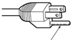
CAUTION: This equipment is equipped with a three-pin grounding-type power plug. Do not remove the grounding pin on the power plug. This plug will only fit a grounding-type power outlet. This is a safety feature. If you are unable to insert the plug into the outlet, contact an electrician. Do not defeat the purpose of the grounding plug.
natural_image
Line drawing of a plug with two terminals and a pointed tip, no text or symbols presentDo not remove
Pursuant to at the directive 2004/108/EC, article 9(2)
Panasonic Testing Center
Panasonic Service Europe, a division of Panasonic Marketing Europe GmbH
Winsbergring 15, 22525 Hamburg, F.R. Germany
NOTICE:
- This product has a High Intensity Discharge (HID) lamp that contains mercury. Disposal may be regulated in your community due to environmental considerations. For disposal or recycling information, please contact your local authorities, or the Electronic Industries Alliance: http://www.eiae.org
WARNING:
This equipment has been tested and found to comply with the limits for a Class B digital device, pursuant to Part 15 of the FCC Rules. These limits are designed to provide reasonable protection against harmful interference in a residential installation. This equipment generates, uses and can radiate radio frequency energy and, if not installed and used in accordance with the instructions, may cause harmful interference to radio communications. However, there is no guarantee that interference will not occur in a particular installation. If this equipment does cause harmful interference to radio or television reception, which can be determined by turning the equipment off and on, the user is encouraged to try to correct the interference by one or more of the following measures:
- Reorient or relocate the receiving antenna.
- Increase the separation between the equipment and receiver.
- Connect the equipment into an outlet on a circuit different from that to which the receiver is connected.
- Consult the dealer or an experienced radio/TV technician for help.
FCC CAUTION: To assure continued compliance, follow the attached installation instructions and use only shielded interface cables when connecting to computer and/or peripheral devices. Any changes or modifications not expressly approved by Panasonic Corp. of North America could void the user's authority to operate this device.
FCC RF Exposure Warning: (if provided with wireless device)
- This equipment complied with FCC radiation exposure limits set forth for an uncontrolled environment.
- This equipment has been approved for mobile operation and requires minimum 20 cm spacing be provided between antenna(s) and all person's body (excluding extremities of hands, wrist and feet) during wireless modes of operation.
- This equipment may not be used with other installed transmitters, which may be capable of simultaneous transmission.
WARNING:
- Not for use in a computer room as defined in the Standard for the Protection of Electronic Computer/Data Processing Equipment, ANSI/NFPA 75.
- For permanently connected equipment, a readily accessible disconnect device shall be incorporated in the building installation wiring.
- For pluggable equipment, the socket-outlet shall be installed near the equipment and shall be easily accessible.
Declaration of Conformity
Model Number: PT-FW300NTU/PT-FW300U
Trade Name: Panasonic
Responsible party: Panasonic Corporation of North America
Address: One Panasonic Way, Secaucus, New Jersey 07094
Telephone number: (888) 411 - 1996
E-mail: projectorsupport@us.panasonic.com
This device complies with Part 15 of the FCC Rules. Operation is subject to the following two conditions: (1) This device may not cause harmful interference, and (2) this device must accept any interference received, including interference that may cause undesired operation.
Information on Disposal in other Countries outside the European
These symbols are only valid in the European Union.
If you wish to discard this product, please contact your local authorities or dealer and ask for the correct method of disposal.

Contents
Quick steps
- Set up your projector See "Setting up" on page 15.

- Connect with other devices See "Connections" on page 19.

- Prepare the Remote control See "Remote control" on page 14.

- Start projecting See “Switching the projector on/off” on page 21.

- Adjust the image See "Menu Navigation" on page 30.
- When you start the projection for the first time, the minimum required setting screen for projection will be displayed. See “Minimum required setting screen” on page 11.
Important Information
Important Safety Notice.... 2
Precautions with regard to safety.... 6
WARNINGS 6
CAUTIONS....7
Cautions when transporting 8
Cautions when installing 8
Cautions on use 9
Security 9
Accessories....10
Preparation
Read this first 11
Minimum required setting screen....11
About Your Projector.... 12
Projector body....12
Remote control....14
Getting Started
Setting up.... 15
Screen size and throw distance 15
Projection method 16
Front leg adjusters and throwing angle....16
Lens shift and positioning....17
Connections.... 19
Before connection to the projector 19
Connecting example: Computers....19
Connecting example: AV equipment....20
Basic Operation
Switching the projector on/off 21
Power cord....21
Power indicator 22
Switching on the projector....23
Switching off the projector....23
Projecting an image 24
Selecting the input signal 24
Positioning the image....24
Remote control operation.... 25
Operating range 25
Setting up the image position automatically....25
Switching the input signal....26
Enlarging the centered area....26
Capturing an image....27
Stopping the projection 27
Resetting to the factory default settings....27
Projecting an image in INDEX-WINDOW mode......27
Using an assigned function....28
Projecting 2 different source image at a time....28
Using the laser pointer 29
Controlling the volume of the speaker....29
Settings Maintenance
Menu Navigation ....30
Main menu and Sub-menu....30
Navigating through the menu 32
PICTURE menu....33
PICTURE MODE 33
CONTRAST 33
BRIGHTNESS.... 33
COLOR 33
TINT....33
SHARPNESS.... 33
WHITE BALANCE RED 33
WHITE BALANCE GREEN.... 33
WHITE BALANCE BLUE 33
COLOR TEMPERATURE.... 34
DAYLIGHT VIEW.... 34
DIGITAL CINEMA REALITY 34
NOISE REDUCTION 34
TV-SYSTEM 34
RGB/YPBPR 34
POSITION menu 35
KEYSTONE 35
SHIFT....35
SHIFT V 35
DOT CLOCK.... 35
CLOCK PHASE 35
OVER SCAN.... 35
ASPECT....36
FRAME LOCK.... 37
DISPLAY OPTION menu ....38
ON-SCREEN DISPLAY 38
DVI-D IN....38
CLOSED CAPTION SETTING.... 38
SCREEN SETTING 38
STARTUP LOGO.... 39
AUTO SETUP.... 39
SIGNAL SEARCH.... 39
BACK COLOR 39
WIDE MODE.... 39
SXGA MODE 39
OTHER FUNCTIONS 40
PROJECTOR SETUP menu ....41
STATUS....41
COMPUTER2 SELECT 41
NO SIGNAL SHUT-OFF 41
INITIAL START UP....41
INSTALLATION 42
HIGH ALTITUDE MODE....42
EMULATE....42
FUNCTION BUTTON....42
AUDIO SETTING....42
TEST PATTERN....43
INITIALIZE ALL.... 43
FILTER COUNTER RESET 43
SECURITY menu 44
PASSWORD 44
PASSWORD CHANGE....44
TEXT DISPLAY....44
TEXT CHANGE 44
MENU LOCK 45
MENU LOCK PASSWORD.... 45
CONTROL DEVICE SETUP....45
NETWORK menu 46
Items in NETWORK menu.... 46
TEMP, LAMP and FILTER Indicators 47
Managing the indicated problems.... 47
Care and Replacement.... 48
Cleaning the projector 48
Replacing the Lamp unit.... 48
Replacing the Auto Cleaning Filter (ACF) 49
Troubleshooting 51
Appendix
Technical Information 52
List of compatible signals 52
Serial terminal.... 53
Computer connection guidance.... 54
REMOTE terminal 55
DVI-D IN terminal 56
Ceiling mount bracket safeguards.... 56
Screen size and throw distance for 16:9 aspect ratio..... 57
Screen size and throw distance for 4:3 aspect ratio..... 57
Specifications 58
Dimensions....60
Trademark acknowledgements 60
Index....61
MISES EN GARDE....66
Precautions with regard to safety
WARNINGS
If you notice smoke, strange smells or noise coming from the projector, disconnect the power plug from the wall outlet.
- Do not continue to use the projector in such cases, otherwise fire or electric shocks could result.
- Check that no more smoke is coming out, and then contact an Authorized Service Center for repairs.
- Do not attempt to repair the projector yourself, as this can be dangerous.
Do not install this projector in a place which is not strong enough to take the full weight of the projector.
- If the installation location is not strong enough, it may fall down or tip over, and severe injury or damage could result.
Installation work (such as ceiling suspension) should only be carried out by a qualified technician.
- If installation is not carried out correctly, there is the danger that injury or electric shocks may occur.
- Do not use other than an authorized ceiling mount bracket.
If foreign objects or water get inside the projector, or if the projector is dropped or the cabinet is broken, disconnect the power plug from the wall outlet.
- ● Continued use of the projector in this condition may result in fire or electric shocks.
- Contact an Authorized Service Center for repairs.
The wall outlet shall be installed near the equipment and shall be easily accessible.
- ● Unplug the power plug from the wall outlet immediately when problem occurred.
Do not overload the wall outlet.
- If the power supply is overloaded (for example, by using too many adapters), overheating may occur and fire may result.
Never attempt to modify or disassemble the projector.
● ● High voltages can cause fire or electric shocks.
- ● For any inspection, adjustment and repair work, please contact an Authorized Service Center.
Clean the power plug regularly to prevent it from becoming covered in dust.
- If dust builds up on the power plug, the resulting humidity can damage the insulation, which could result in fire. Pull the power plug out from the wall outlet and wipe it with a dry cloth.
- If not using the projector for an extended period of time, pull the power plug out from the wall outlet.
Do not handle the power plug with wet hands.
● Failure to observe this may result in electric shocks.
Insert the power plug securely into the wall outlet.
- Do not use other than the provided power cord.
- If the plug is not inserted correctly, electric shocks or overheating could result.
- Do not use plugs which are damaged or wall outlets which are coming loose from the wall.
Do not place the projector on top of surfaces which are unstable.
- If the projector is placed on top of a surface which is sloped or unstable, it may fall down or tip over, and injury or damage could result.
Do not place the projector into water or let it become wet.
- Failure to observe this may result in fire or electric shocks.
Do not do anything that might damage the power cord or the power plug.
- Do not damage the power cord, make any modifications to it, place it near any hot objects, bend it excessively, twist it, pull it, place heavy objects on top of it or wrap it into a bundle.
- If the power cord is used while damaged, electric shocks, short-circuits or fire may result.
- Ask an Authorized Service Center to carry out any repairs to the power cord that might be necessary.
Do not place the projector on soft materials such as carpets or sponge mats.
- ● Doing so may cause the projector to overheat, which can cause burns, fire or damage to the projector.
Do not place liquid containers on top of the projector.
- If water spills onto the projector or gets inside it, fire or electric shocks could result.
- If any water gets inside the projector, contact an Authorized Service Center.
Do not insert any foreign objects into the projector.
- Do not insert any metal objects or flammable objects into the projector or drop them onto the projector, as doing so can result in fire or electric shocks.
Do not allow the + and - terminals of the batteries to come into contact with metallic objects such as necklaces or hairpins.
● ● Failure to observe this may cause the batteries to leak, overheat, explode or catch fire.
- Store the batteries in a plastic bag and keep them away from metallic objects.
Do not touch the leaked liquid from the batteries.
- If you touch the leaked liquid, it may hurt your skin. Immediately wash away the liquid with water and seek medical advice.
- If you get the leaked liquid in your eye, it may cause blindness or damage. Never rub your eye, and immediately wash away the liquid with water and seek medical advice.
During a thunderstorm, do not touch the projector or the cable.
● ● Electric shocks can result.
Do not use the projector in a bath or shower.
● ● Fire or electric shocks can result.
Do not place your skin into the light beam while the projector is being used.
- Strong light is emitted from the projector's lens. If you place directly into this light, it can hurt or damage your skin.
Do not look into the lens while the projector is being used.
- Strong light is emitted from the projector's lens. If you look directly into this light, it can hurt and damage your eyes.
- Be especially careful not to let young children look into the lens. In addition, turn off the power and disconnect the power plug when you are away from the projector.
Do not place your hands or other objects close to the air outlet port.
- Heated air comes out of the air outlet port. Do not place your hands or face, or objects which cannot withstand heat close to this port [allow at least 50 cm (20") of space], otherwise burns or damage could result.
Replacement of the lamp is recommended to be carried out by a qualified technician.
● ● The lamp has high internal pressure. If improperly handled, explosion might result.
● The lamp can easily become damaged if struck against hard objects or dropped, and injury or malfunctions may result.
When replacing the lamp, allow it to cool for at least one hour before handling it.
● ● The lamp cover gets very hot, and touching it can cause burns.
Before replacing the lamp, be sure to disconnect the power plug from the wall outlet.
- Electric shocks or explosions can result if this is not done.
Do not allow infants or pets to touch the remote control unit.
- Keep the remote control unit out of the reach of infants and pets after using it.
CAUTIONS
Do not cover the air inlet port or the air outlet port.
- ● Doing so may cause the projector to overheat, which can cause fire or damage to the projector.
- Do not place the projector in narrow, badly ventilated places such as closets or bookshelves.
- Do not place the projector on cloth or papers, as these materials could be drawn into the air inlet port.
Do not set up the projector in humid or dusty places or in places where the projector may come into contact with oily smoke or steam.
- Using the projector under such conditions may result in fire, electric shocks or plastic deterioration. The plastic deterioration may cause the falling down of the projector which is mounted on the ceiling.
Do not set up the projector in a high temperature environment, such as near a heater or in direct sunlight.
● ● Failure to observe this may result in fire, malfunction or plastic deterioration.
Do not set up the projector outdoors.
● ● The projector is designed for indoor use only.
When disconnecting the power cord, hold the plug, not the cord.
- If the power cord itself is pulled, the cord will become damaged, and fire, short-circuits or serious electric shocks may result.
Always disconnect all cables before moving the projector.
- Moving the projector with cables still attached can damage the cables, which could cause fire or electric shocks to occur.
Do not place any heavy objects on top of the projector.
● ● Failure to observe this may cause the projector to become unbalanced and fall, which could result in damage or injury.
Do not short-circuit, heat or disassemble the batteries or place them into water or fire.
● ● Failure to observe this may cause the batteries to overheat, leak, explode or catch fire, and burns or other injury may result.
When inserting the batteries, make sure the polarities (+ and -) are correct.
- If the batteries are inserted incorrectly, they may explode or leak, and fire, injury or contamination of the battery compartment and surrounding area may result.
Use only the specified batteries.
- If incorrect or different kind of batteries are used, they may explode or leak, and fire, injury or contamination of the battery compartment and surrounding area may result.
Do not mix old and new batteries.
- If the batteries are used mixing old and new, they may explode or leak, and fire, injury or contamination of the battery compartment and surrounding area may result.
Remove the used batteries from the remote control promptly.
- If you leave used batteries in the remote control for an extended period of time, it may cause liquid leaking, abnormal internal temperature rising or explosion.
If not using the projector for an extended period of time, disconnect the power plug from the wall outlet and remove the batteries from the remote control.
- If dust builds up on the power plug, the resulting humidity may damage the insulation, which could result in fire.
- Keeping or leaving the remote control with batteries inside may cause insulation deterioration, electrical leakage or explosion which could result in fire.
Do not put your weight on this projector.
- ● You could fall or the projector could break, and injury may result.
- Be especially careful not to let young children stand or sit on the projector.
Disconnect the power plug from the wall outlet as a safety precaution before carrying out any cleaning.
● ● Electric shocks can result if this is not done.
If the lamp has broken, ventilate the room immediately. Do not touch or bring your face close to the broken pieces.
● ● Failure to observe this may cause the user to absorb the gas which was released when the lamp broke and which contains nearly the same amount of mercury as fluorescent lamps, and the broken pieces may cause injury.
- If you believe that you have absorbed the gas or that the gas has got into your eyes or mouth, seek medical advice immediately.
- Ask your dealer about the replacement of the lamp unit and check the inside of the projector.
Ask an Authorized Service Center to clean inside the projector at least once a year.
- If dust is left to build up inside the projector without being cleaned out, it can result in fire or problems with operation.
- ● It is a good idea to clean the inside of the projector before the season for humid weather arrives. Ask your nearest Authorized Service Center to clean the projector when required. Please discuss with the Authorized Service Center regarding cleaning costs.
Do not use chemical treated wipes when cleaning.
- Using chemical treated wipes may result in plastic distortion or deterioration.
We are constantly making efforts to preserve and maintain a clean environment. Please take non repairable units back to your dealer or a recycling company.
Cautions when transporting
Do not subject the projector to excessive vibration or shocks.
● ● The projector lens need to be handled with care.
- Cover the lens with the lens cover when transporting the projector.
When transporting the projector, hold the body at the bottom securely.
- Do not hold the adjuster legs or the top cover to move the projector, as this may damage the projector.
Cautions when installing
Avoid setting up in places which are subject to vibration or shocks.
● ● The internal parts can be damaged, which may cause malfunctions or accidents.
Avoid setting up in places which are subject to sudden temperature changes, such as near an air conditioner or lighting equipment.
● ● The life of the lamp may be shortened or the projector may be turned off. See "TEMP indicator" on page 47.
Do not set up the projector near high-voltage power lines or near motors.
● ● The projector may be subject to electromagnetic interference.
If installing the projector to the ceiling, ask a qualified technician to carry out all installation work.
- ● You will need to purchase the separate installation kit (Model No. ET-PKF100H, ET-PKF100S).
Furthermore, all installation work is should only be carried out by a qualified technician. - See "Ceiling mount bracket safeguards" on page 56 for the safety cable installation.
If using this projector at high elevations 1 400 - 2 700 m (4 593 - 8 858 ft) sea level, set the HIGH ALTITUDE MODE to ON. See “HIGH ALTITUDE MODE” on page 42.
- Failure to observe this may result in malfunctions or the life of the lamp or the other components may be shortened.
Cautions on use
In order to get the best picture quality
- ● Draw curtains or blinds over any windows and turn off any lights near the screen to prevent outside light or light from indoor lamps from shining onto the screen.
Do not touch the surfaces of the lens or the front glass with your bare hands.
- If the surface of the lens becomes dirty from fingerprints or anything else, this will be magnified and projected onto the screen. Moreover, when not using the projector, close the front panel cover.
Liquid crystal panel
- Do not project the same image for long periods of time, as this may remain as an afterimage on the liquid crystal panel. Display the white screen test pattern for more than an hour to remove it. See "TEST PATTERN" on page 43.
● The liquid crystal panel of the projector is built with very high precision technology to provide fine picture details. Occasionally, a few stuck pixels may appear on the screen as fixed points of blue, green or red. It is recommended to switch off the projector once and try after 1 hour later again. Please note that this does not affect the performance of your LCD.
The projector has a high pressure mercury lamp and that is characterized as follows.
● ● The brightness of the lamp depends on the duration of use.
● ● The lamp may explode or shorten the lamp life by shocks or chipping damage.
- ● The lamp may explode only occasionally after using the projector.
- ● The lamp may explode if using the projector after the instructed lamp replacement timing.
- When the lamp exploded, it emits internal smoke-like gas.
● The lamp life is depends on individual lamp characteristics, usage condition and the installation environment. Especially the consecutive use of the projector for more than 10 hours, or the frequent switching on or off may greatly affect on the lamp life even when lamp usage is less than 1 year.
Optical components
- If you use the projector consecutively 12 hours every day, the optical components may need to be replaced in less than 1 year.
Security
Take the safety measures for use of the projector that should cover the following envisioned incidents.
● ● The leakage of your personal registered information.
● Dishonest operation by an untrusted third party.
- Locking out or prevent anyone else from using the projector by an untrusted third party.
Security instruction
● ● The connecting network must be secured by firewall or others.
- Change your password regularly.
- ● Do not use password too simple to guess.
● ● The Authorized Service Center will never ask you for the password.
- Do not share your password with anyone else.
- Password the projector and restrict access to authorized users only.
Accessories
Make sure the following accessories are provided with your projector.
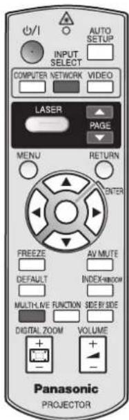
Remote control for PT-FW300NTU (x1) N2QAYB000305
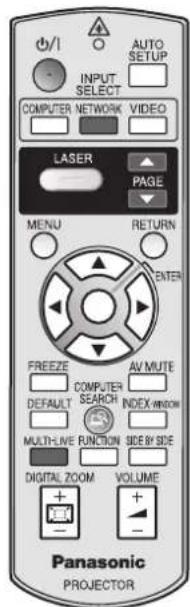
Remote control for PT-FW300U (x1) N2QAYB000367
AA batteries for remote control (x2)

Power cord (x1) K2CM3DH00016
Power cord secure lock (x1) TTRA0182
Safety cable
TTRA0141
Attachment screw (x1) Safety cable (x1)

natural_image
Simple line drawing of a door handle and seat (no text or symbols)CD-ROM (x1) TQBH9012

natural_image
Simple circular diagram with concentric rings and a diagonal line, no text or symbols present.* The protectors for enclosed products, such as a plug cover or foam cartons, must be treated properly.
* Contact to an Authorized Service Center for lost accessories.
Read this first
Minimum required setting screen
When you start the projection for the first time, the minimum required setting screen for projection will be displayed.
● INITIAL SETTING
- Select the required language setting by pressing
◀▶, then press the ENTER button.
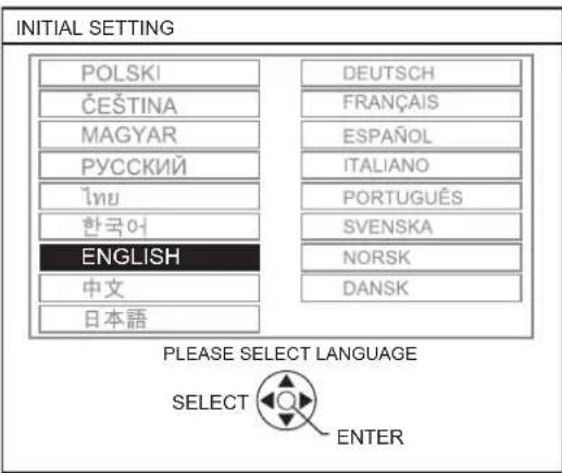
-
Select the minimum required settings to start the projection.
-
Press the RETURN button to return to the language setting menu.
- Press ▲ ▼ to move through the menu items.
- Press ◀▶ to select the required setting.
- Press the ENTER button to complete the setting and start the projection.
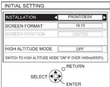
INSTALLATION
Select the required installation method.
| FRONT/DESK | Setting on a desk/floor and projecting from front |
| FRONT/CEILING | Mounting on the ceiling and projecting from front |
| REAR/DESK | Setting on a desk/floor and projecting from rear |
| REAR/CEILING | Mounting on the ceiling and projecting from rear |
SCREEN FORMAT
Select the required screen format by pressing ◀▶.
● ● 16:10 When project on a 16:10 or 4:3 screen.
● ● 16:9 When project on a 16:9 screen.
SCREEN POSITION
When SCREEN FORMAT menu is set to 16:9, you can select the menu display position by pressing ◀▶.
- ● LOW Displays the menu in the lower part of the screen.
- ● CENTER Displays the menu in the middle of the screen.
● ● HIGH Displays the menu in the upper part of the screen.
HIGH ALTITUDE MODE
If you use the projector at high elevation, the HIGH ALTITUDE MODE setting need to be ON to set the fan speed high.
● OFF The fan speed is low.
● ON The fan speed is high.
NOTE:
- At 1 400 - 2700 m (4 593 - 8 858 ft) above sea level, the setting must be ON.
- The loudness of fan noise depends on the HIGH ALTITUDE MODE setting.
NOTE:
- Once you finish the minimum requirement setting, it will not be displayed again unless the projector is initialized. See "INITIALIZE ALL" on page 43.
- You can change the each setting from the main menu. See "Menu Navigation" on page 30.
About Your Projector
Projector body
● Top and front view
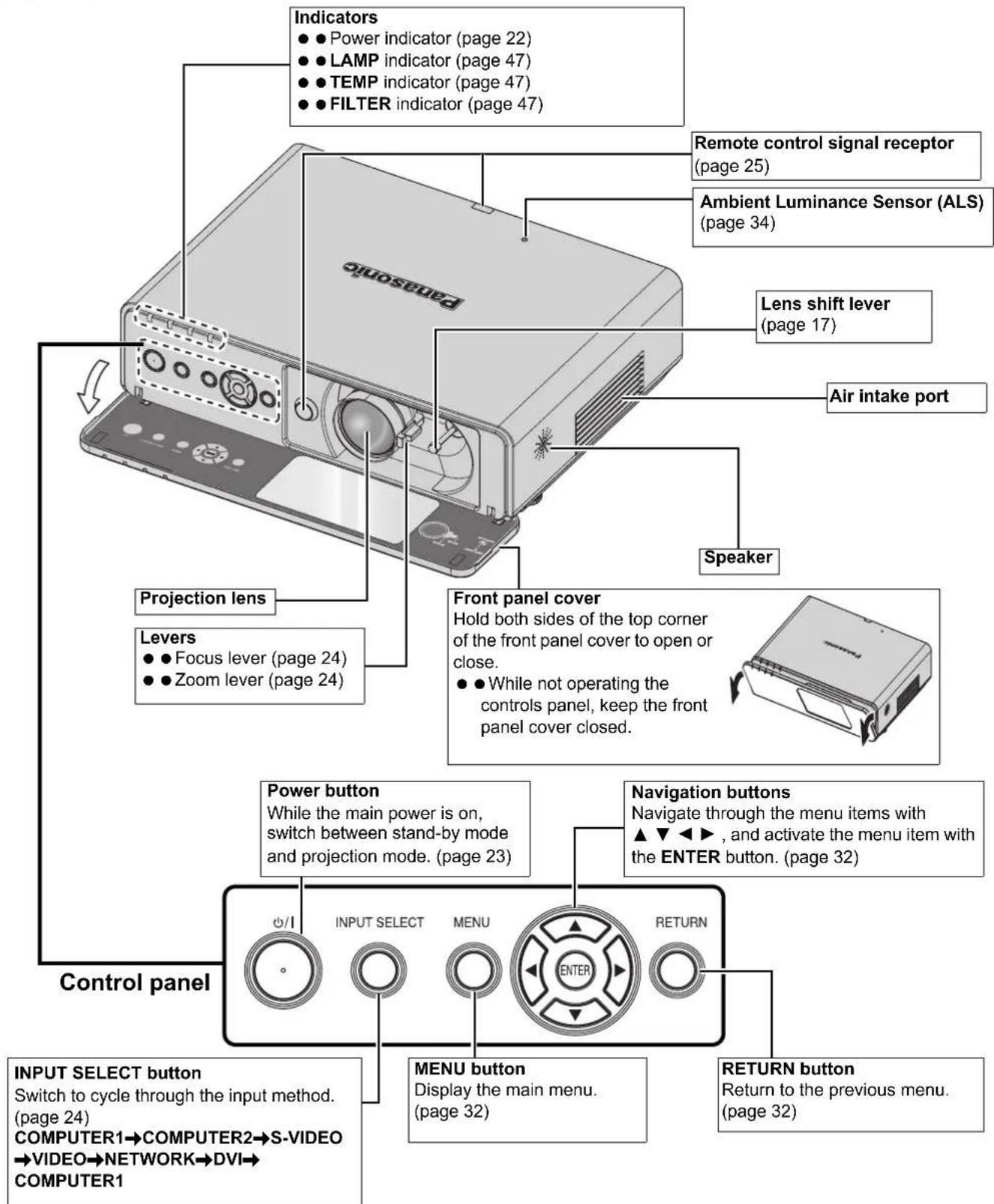
NOTE:
- Do not cover the ventilation openings or place anything within 50 cm (20") of them as this may cause damage or injury.
- While the projector is not in use, keep the front panel cover closed to protect the lens.
Back and bottom view
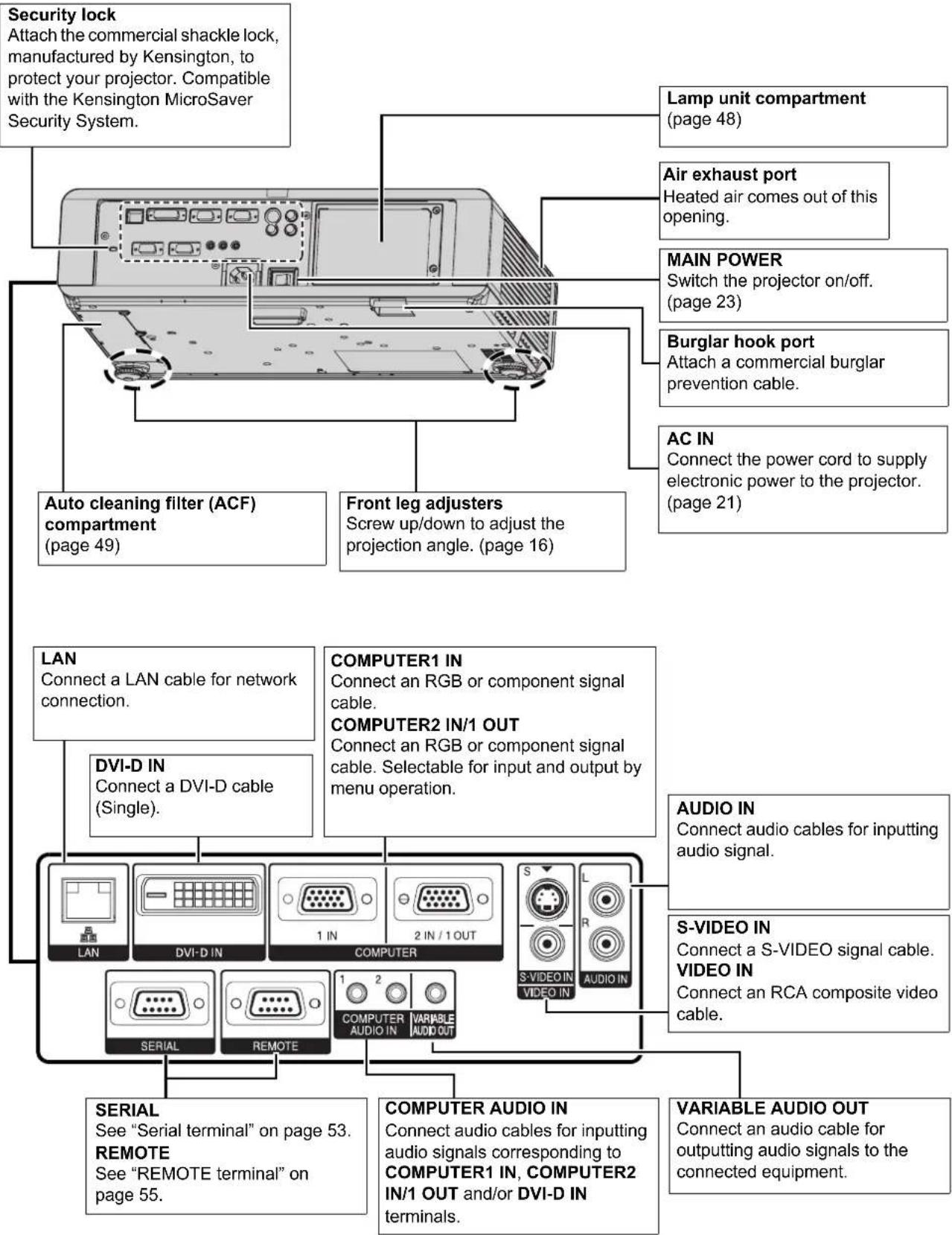
NOTE:
- Do not cover the ventilation openings or place anything within 50 cm (20") of them as this may cause damage or injury.
- When a cable is connected to the VARIABLE AUDIO OUT, the built-in speaker will be disabled.
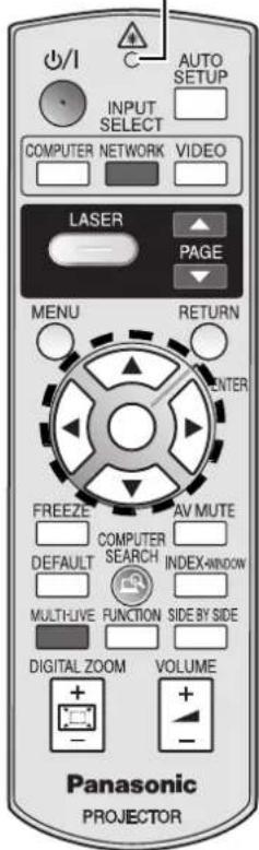
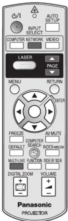
Remote control
Attaching a hand strap
You can attach a favorite strap on to the remote control.

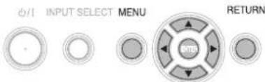
Top view
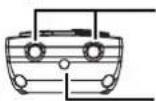
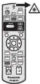
Remote control signal emitters (page 25)
Laser pointer beam emitter (page 29)
Remote control indicator
Pressing any button except the LASER button, the remote control indicator will flash. Pressing the LASER button, it will lit.
Power button
While the MAIN POWER is on, switch between standby mode and projection mode. (page 21)
Project a laser pointer. (page 29)
Display the main menu. (page 32)
Navigate through the menus with ▲▼◀▶, and activate the menu item with the ENTER button. (page 32)
Capture the projected image as a frozen picture. (page 27)
Reset some of the settings to the factory default settings. (page 27)
Assign the frequently use functions from the options for shortcut. (page 27)
Control to change the scale by means of digital zoom. (page 26)
/I

SER

MENU


FREEZE

DEFAULT

FUNCTION

DIGITAL ZOOM

(Shown as PT-FW300NTU)
AUTO


the projected image of COMPUTER/DVI signal. (page 25)
COMPUTER


RETURN

AV MUTE

INDEX-WINDOW

continues.
SIDE BY SIDE

Automatically adjust the
setting of SHIFT, DOT
CLOCK, CLOCK PHASE
and SIGNAL SEARCH for
cted image of COMPUTER/
al. (page 25)
Switch the required input
signal button to select.

Return to the previous menu.
(page 32)
Turn off the projection
temporarily. (page 27)
Display the frozen image
while the display of
subsequent images
. (page 27)
: Display 2 different source
images at a time.
(page 27)
Control to adjust the volume
of the speaker. (page 29)
MULTI-LIVE

NETWORK

▲

COMPUTER
SEARCH

These buttons are for network control. See the contents of the provided CD-ROM for instructions. The COMPUTER
SEARCH button is for PT-FW300NTU only.
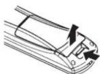
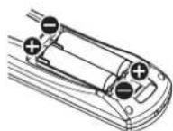
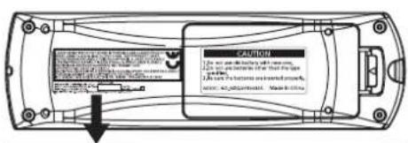
Battery compartment
- Press the tab and lift up the cover.
- Insert the batteries according to the polarity diagram indicated inside.
NOTE:
- Do not drop the remote control.
- Avoid contact with liquids or moisture.
- Use manganese batteries or alkaline batteries with the remote control.
- Do not attempt to modify or disassemble the remote control. Contact an Authorized Service Center for repairs.
- Do not keep pressing the remote control buttons as this may shorten battery life.
- Do not point the laser in other people's eyes or stare into beam.
- See "Remote control operation" on page 25.
Setting up
Screen size and throw distance
You can adjust the projection size with 2.0x zoom lens. Calculate and define the throw distance as follows.
Projected image
Shown as 16:10
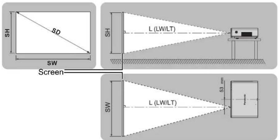
All measurements and the calculation results below are approximate and may differ slightly from the actual measurements.
| Projection size (16 : 10) Throw distance (L) | |||||
| Screen Diagonal (SD) | Screen height (SH) | Screen width (SW) | Minimum distance (LW) | Maximum distance (LT) | |
| (0.84 m) 33" | 0.44 m (1'5") | 0.71 m (2'3") | 1.8 m (5'10") | ||
| (1.02 m) 40" | 0.54 m (1'9") | 0.86 m (2'9") | 1.1 m (3'7") | 2.3 m (7'6") | |
| (1.27 m) 50" | 0.67 m (2'2") | 1.08 m (3'6") | 1.4 m (4'7") | 2.8 m (9'2") | |
| (1.52 m) 60" | 0.81 m (2'7") | 1.29 m (4'2") | 1.7 m (5'6") | 3.4 m (11'1") | |
| (1.78 m) 70" | 0.94 m (3'1") | 1.51 m (4'11") | 2.0 m (6'6") | 4.0 m (13'1") | |
| (2.03 m) 80" | 1.08 m (3'6") | 1.72 m (5'7") | 2.3 m (7'6") | 4.6 m (15'1") | |
| (2.29 m) 90" | 1.21 m (3'11") | 1.94 m (6'4") | 2.6 m (8'6") | 5.1 m (16'8") | |
| (2.54 m) 100" | 1.35 m (4'5") | 2.15 m (7') | 2.9 m (9'6") | 5.7 m (18'8") | |
| (3.05 m) 120" | 1.62 m (5'3") | 2.58 m (8'5") | 3.4 m (11'1") | 6.9 m (22'7") | |
| (3.81 m) 150" | 2.02 m (6'7") | 3.23 m (10'7") | 4.3 m (14'1") | 8.6 m (28'2") | |
| (5.08 m) 200" | 2.69 m (8'9") | 4.31 m (14'1") | 5.7 m (18'8") | 11.5 m (37'8") | |
| (6.35 m) 250" | 3.37 m (11') | 5.38 m (17'7") | 7.2 m (23'7") | 14.3 m (46'10") | |
| (7.62 m) 300" | 4.04 m (13'3") | 6.46 m (21'2") | 8.6 m (28'2") | 17.2 m (56'5") | |
Calculation methods
$$ \mathrm{SW} (\mathrm{m}) = \mathrm{SD} (") \times 0. 0 2 1 5 \mathrm{SH} (\mathrm{m}) = \mathrm{SD} (") \times 0. 0 1 3 5 $$
$$ \mathrm{LW} (\mathrm{m}) = 0. 0 2 8 9 \times \mathrm{SD} (^ {\prime \prime}) - 0. 0 4 6 \mathrm{LT} (\mathrm{m}) = 0. 0 5 7 6 \times \mathrm{SD} (^ {\prime \prime}) - 0. 0 6 1 $$
NOTE:
• See page 57 for the screen size and throw distance of 4:3/16:9.
- Do not use the projector at a raised or a horizontally tilted position as it may cause malfunction of the projector.
- Make sure the projector lens surface is parallel with the screen. You can tilt the projector body approximately ± 30^ vertically. Overtilting may result in shortening the component's life.
- For the best quality of the projection image, install a screen where sun light or room light does not shine directly onto the screen. Close window shades or curtains to block the lights.
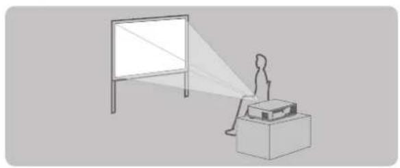
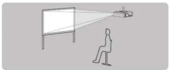
Projection method
You can use the projector with any of the following 4 projection methods. To set the desired method in the projector, See "INSTALLATION" on page 42.
Setting on a desk/floor and projecting from front
natural_image
Simple line drawing of a person sitting at a desk watching a projector screen (no text or symbols)Setting on a desk/floor and projecting from rear
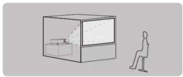
natural_image
Simple line drawing of a person sitting in a chair next to a transparent display case (no text or symbols)INSTALLATION: FRONT/DESK INSTALLATION: REAR/DESK
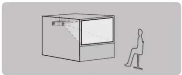
Mounting on the ceiling and projecting from front
natural_image
Simple line drawing of a person sitting at a desk observing a projector on a screen (no text or symbols)INSTALLATION: FRONT/CEILING
Mounting on the ceiling and projecting from rear
natural_image
Simple line drawing of a person sitting in front of a rectangular display unit (no text or symbols)INSTALLATION: REAR/CEILING
NOTE:
- A translucent screen is required for rear projection.
- When mounting the projector on the ceiling, the optional ceiling mount bracket (ET-PKF100H, ET-PKF100S) is required.
- See "Ceiling mount bracket safeguards" on page 56.
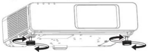
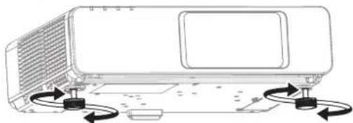
Front leg adjusters and throwing angle
You can screw up/down the front leg adjusters to control the angle of the projector for adjusting the throwing angle. See "Positioning the image" on page 24.
natural_image
Diagram of a portable air conditioner unit with scroll arrows indicating rotation (no text or symbols)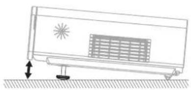
natural_image
Diagram of a car air conditioner unit with airflow direction indicated by arrows (no text or symbols)NOTE:
- Heated air comes out of the air exhaust port. Do not touch the air exhaust port directly.
- If keystone distortion occurs, see "KEYSTONE" on page 35.
- Screw up the adjuster legs, and an audible click will be heard as the limit.
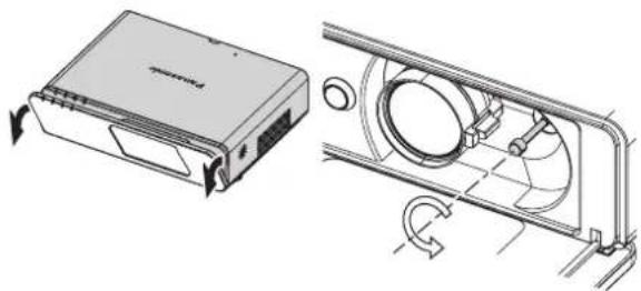
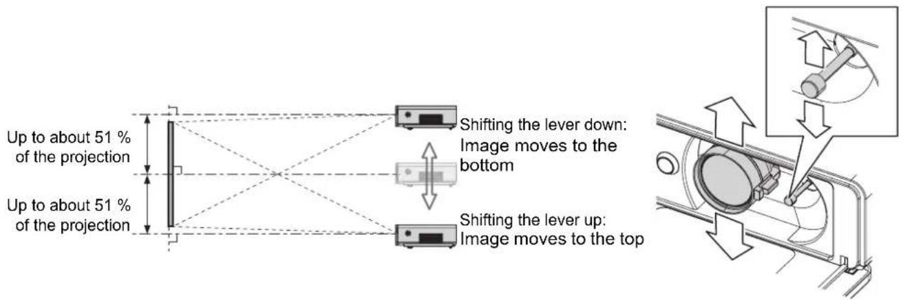
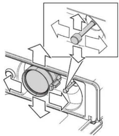
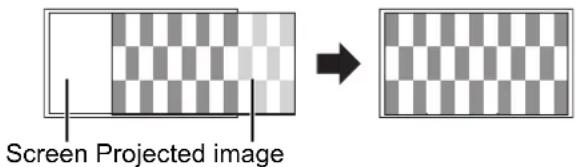
Lens shift and positioning
If the projector is not positioned right in front of the center of the screen, you can adjust the projected image position by moving the lens shift lever within the shift range of the lens.
■ Adjusting the lens shift lever
- Open the front panel cover.
- Screw the lens shift lever counterclockwise to unlock.
- Move the lens shift lever to adjust the projected image position.
- Screw the lens shift lever clockwise to lock.
natural_image
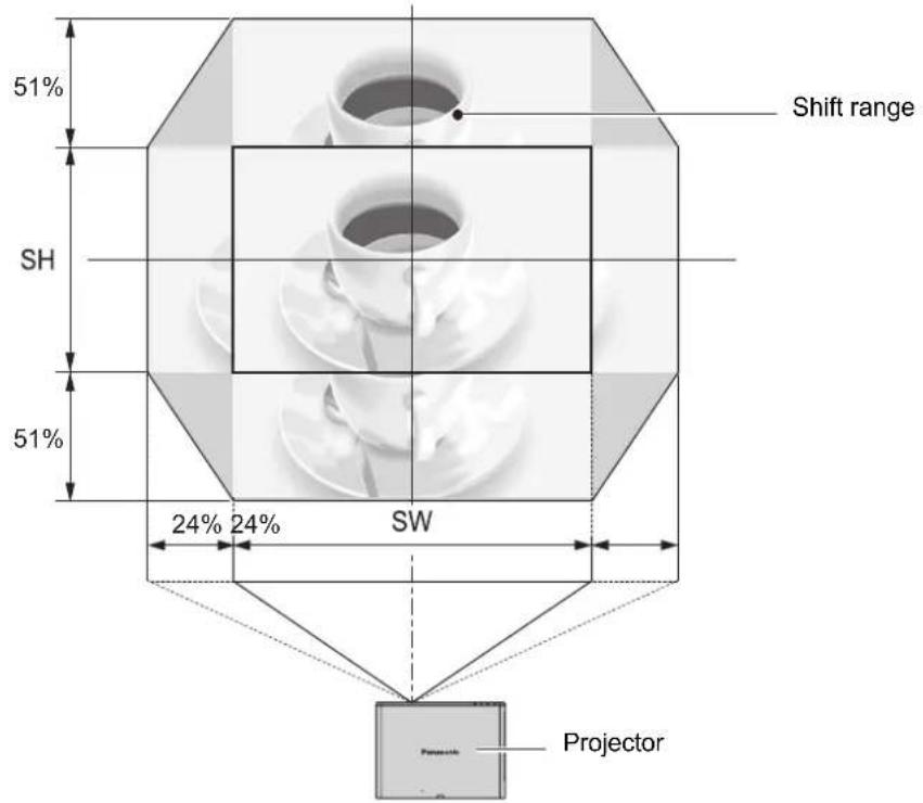
Technical line drawing of a device housing and its internal fan assembly (no text or symbols)● Horizontal shift
You can place the projector where the projector lens is up
to 24% horizontally off-center from the screen and then adjust the image position with the lens shift lever.
Up to about 24 % of the projection
Up to about 24 % of the projection
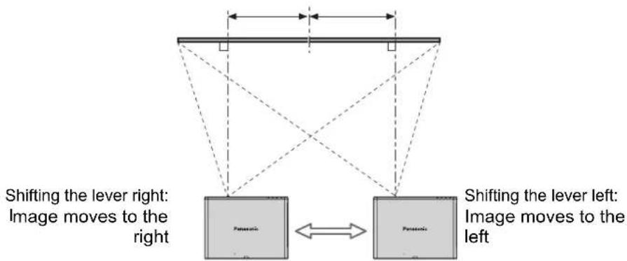
flowchart
graph TD
    A["Shifting the lever right: Image moves to the right"] --> B["Image"]
    C["Shifting the lever left: Image moves to the left"] --> D["Image"]
    B <--> D
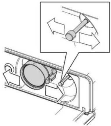
natural_image
Mechanical assembly diagram showing a rotating component with directional arrows indicating motion (no text or symbols present)● Vertical shift
You can place the projector where the projector lens is up to 51% vertically off-center from the screen and the adjust the image position with the lens shift lever.
■ Projector location range
You can determine where to locate the screen and the projector by considering the lens shift possibilities. See "Positioning the image" on page 24.
● When the screen position is fixed
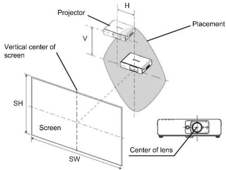
● When the projector position is fixed
NOTE:
- When the projector is located right in front of the screen and the lens shift lever is centered, you will get the best quality of the projection image.
- When the lens shift lever is at the vertical limit of the shift range, you cannot move the lever to the horizontal limit, likewise when the lens shift lever is at the horizontal limit of the shift range, you cannot move the lever to the vertical limit.
- When the projector is tilted and you adjust KEYSTONE, the center of the screen and the lens need to be realigned.
- Do not attempt to pull the lens shift lever hard while adjusting.
Connections
Before connection to the projector
- Read and follow the operating and connecting instructions of each peripheral device.
● ● The peripheral devices must be turned off. - Use cables that match each peripheral device to be connected.
- If the input signal is affected by signal jitter, the projected image may have poor image quality and timebase correction is effective.
- Confirm the type of video signals. See "List of compatible signals" on page 52.
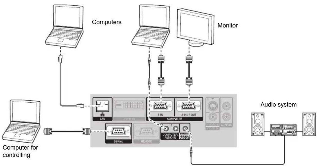
Connecting example: Computers
flowchart
graph TD
    A["Computer for controlling"] --> B["Computer"]
    B --> C["Laptop"]
    C --> D["Computers"]
    D --> E["Laptop"]
    D --> F["Laptop"]
    D --> G["Laptop"]
    D --> H["Monitor"]
    H --> I["Computer"]
    I --> J["LAN"]
    I --> K["SERIAL"]
    I --> L["REMOTE"]
    I --> M["COMPUTER"]
    M --> N["1 IN"]
    M --> O["2 IN / 1 OUT"]
    M --> P["COMPUTER AUDIO IN"]
    M --> Q["MINIABLE AUDIO OUT"]
    P --> R["AUDIO system"]
    Q --> S["AUDIO"]
    R --> T["Audio output"]
    S --> T
    T --> U["Computer"]
NOTE:
- Use COMPUTER terminals to input YPBPR signals.
- When connecting to the COMPUTER terminals, you can switch the audio input terminal between COMPUTER AUDIO IN and AUDIO IN. See "AUDIO SETTING" on page 42.
- When COMPUTER2 SELECT in the OPTION menu is set to OUTPUT, do not connect any input signals.
• See CD-ROM contents for the LAN network connection.
LAN terminal
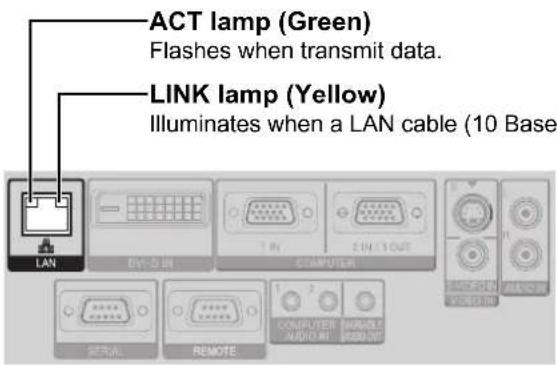
NOTE:
- Do not touch the metal parts of the LAN terminal. Failure to observe this may cause malfunction by static electricity.
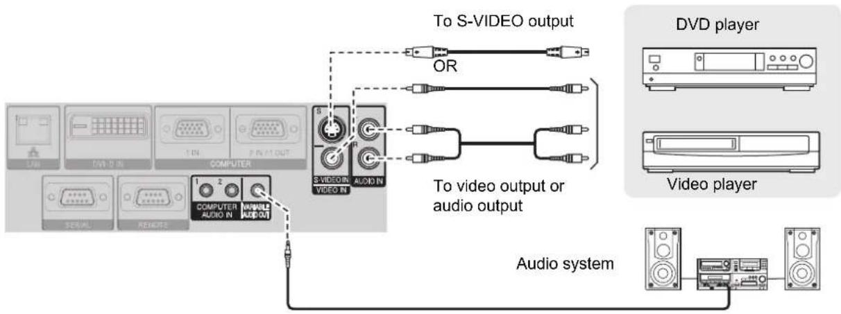
Connecting example: AV equipment
Connecting with VIDEO IN/S-VIDEO IN
flowchart
graph TD
    A["Computer"] -->|1 2| B["Video output"]
    A -->|1 2| C["Audio output"]
    B --> D["To S-VIDEO output"]
    C --> E["To video output or audio output"]
    D --> F["OR"]
    E --> G["OR"]
    F --> H["Video player"]
    G --> I["Video player"]
    H --> J["Audio system"]
    I --> J
    style A fill:#f9f,stroke:#333
    style B fill:#ccf,stroke:#333
    style C fill:#ccf,stroke:#333
    style D fill:#cfc,stroke:#333
    style E fill:#cfc,stroke:#333
    style F fill:#fcc,stroke:#333
    style G fill:#fcc,stroke:#333
    style H fill:#fcc,stroke:#333
    style I fill:#fcc,stroke:#333
    style J fill:#cff,stroke:#333
NOTE:
- When you connect more than one AV equipment, switch the audio connection manually.
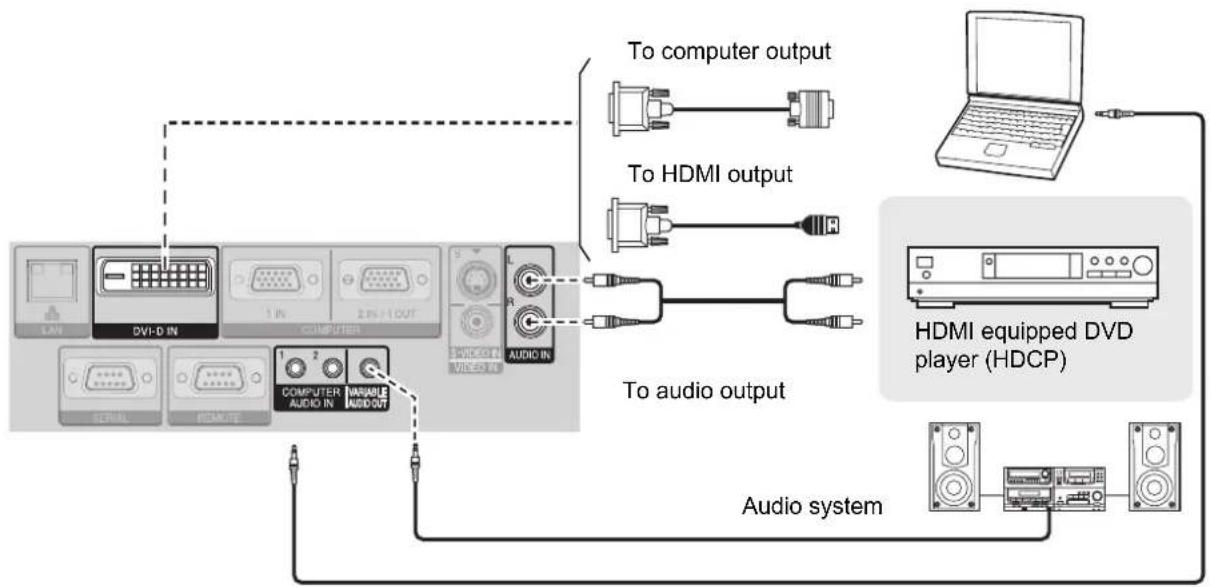
Connecting with DVI-D IN
flowchart
graph TD
    A["Audio system"] --> B["HDMI equipped DVD player (HDCP)"]
    B --> C["To computer output"]
    B --> D["To HDMI output"]
    B --> E["To audio output"]
    C --> F["Computer interface"]
    D --> G["Computer interface"]
    E --> H["Computer interface"]
NOTE:
- DVI-D is single link.
- Prepare a HDMI - DVI-D cable for HDMI connection.
- You may need to change the setting of the DVI EDID in DISPLAY OPTION menu with some DVI-D IN connection. See "DVI-D IN" on page 38.
- Malfunction may occur or other problems could be encountered with some kind of HDMI or DVI equipment.
- When connecting to the DVI-D IN terminal, you can switch the audio input terminal between COMPUTER AUDIO IN 2 and AUDIO IN. See "AUDIO SETTING" on page 42.
Switching the projector on/off
Power cord
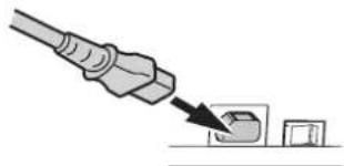
- Connecting
- Make sure the shape of the power plug and the AC IN terminal on the back of the projector match, then push the plug all the way in.
natural_image
Illustration of a plug inserted into a socket with an arrow pointing to it (no text or symbols present)- Align the side of the power cord secure lock with the side guide rail of the AC IN terminal of the projector and slide it in.
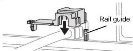
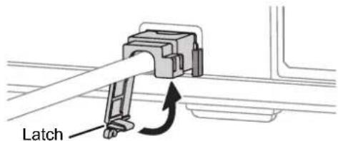
- Place the latch to the latch catcher and press until it clicks.
- Connect the power cord to a wall outlet.
- Disconnecting
- Unplug the power cord from the wall outlet.
- Depress the latch and slide the cover off.
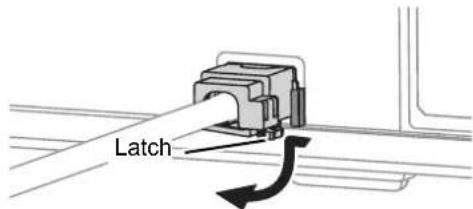
- Slide the power cord secure lock up along the side guide rail and remove.
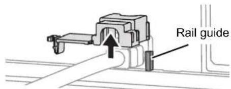
- Hold the plug and unplug the power cord from the AC IN terminal on the back of the projector.
● Power indicator lights in orange if the internal cooling fan is still operating by internal power supply.
NOTE:
- Do not use other than the provided power cord.
- Ensure all the input devices are connected and turned off before connecting the power cord.
- Do not force the connector as this may damage the projector and/or the power cord.
- Dirt or dust build-up around plugs may cause fire or electrical hazards.
- Switch off the power to the projector when not in use.
- If the projector is switched on again while the internal cooling fan is still operating by the internal power supply, it may take a while to start the projection.
- Direct power on function
You can start the projection with only supplying the electric power. See "INITIAL START UP" on page 41.
● Direct power off function
You can switch off the electric power supply any time by unplugging the power plug from the wall outlet or by switching off the main power. The internal lamp cooling fan keeps operating by the internal power supply, and stops automatically when cooled enough.
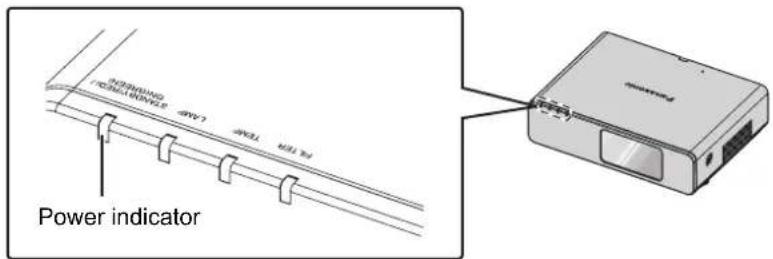
Power indicator
The power indicator informs you the status of the power.
- When the LAMP or TEMP indicator is flashing, you cannot switch on the power. See "TEMP, LAMP and FILTER Indicators" on page 47.
| Indicator status Status | ||
| No illumination or flashing | The MAIN POWER is switched off. | |
| RED | Lit | The MAIN POWER is switched on and the projector is in standby mode.When the LAMP or TEMP indicator is flashing, not available to switch on the power. |
| Flashing | The power is switched off. (When NETWORK STANDBY in NETWORK menu or IN STANDBY MODE of AUDIO SETTING in PROJECTOR SETUP menu is set to ON). Press the power button to start the projection. | |
| GREEN | Flashing The power is switched on and the projector is getting ready to project. | |
| Lit Projecting. | ||
| ORANGE | Lit | The power is switched off and the projector is cooling the lamp. The indicator will light or flash, and start the projection after a short time. |
| Flashing | The power is switched on again when cooling the lamp and recovering to projection mode. | |
NOTE:
- If the projector is switched on again while the internal cooling fan is still operating by the internal power supply, it may take a while to start the projection.
• The electric consumption in standby mode is 4 W.
Switching on the projector
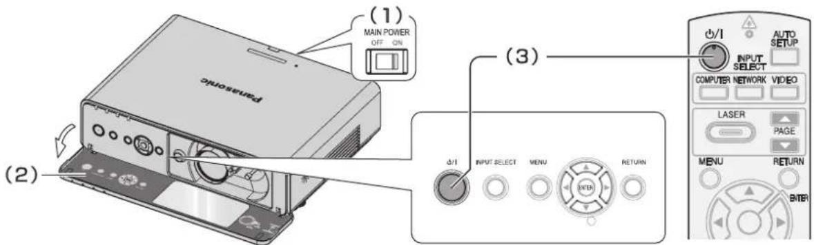
- Switch the MAIN POWER on.
● ● The power indicator lights up in red.
- Open the front panel cover.
● This is not necessary in remote control operation.
- Press the power button.
● The power indicator lights up in green after flashing for a while.
- The STARTUP LOGO will be displayed on the screen. See "STARTUP LOGO" on page 39.
NOTE:
- When starting up the projector, some small rattling or tinkling sound may be heard, or the display may flicker for the characteristics of the lamp. Those are normal and will not affect the performance of the projector.
- When the internal cooling fan is operating, some operational sound may be heard. The loudness of the operational sound depends on the external temperature.
- If you disconnected the power cord or switched off the MAIN POWER while on projecting mode, the projection will start with connecting the power cord or switching on the MAIN POWER. See "INITIAL START UP" on page 41.
Switching off the projector
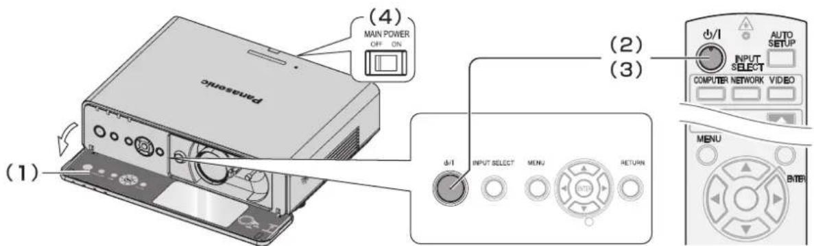
- Open the front panel cover.
● ● This is not necessary in remote control operation.
- Press the power button.
● The confirmation screen is displayed. It will disappear and return to the projection after 10 seconds without any operation.
- To return to the projection, press any button except the power button.
- Press the power button.
● The power indicator lights up in orange while cooling the lamp, then illuminates red when is ready to switch off the MAIN POWER.
- Switch off the MAIN POWER on the back of the projector.
NOTE:
- You can disconnect the power cord or switch off the MAIN POWER instead of following this procedure. See "INITIAL START UP" on page 41.
Projecting an image
Selecting the input signal
- Switch on the connected devices.
- Press the play button of the required device.
- Press the INPUT SELECT buttons to select the required input method if needed. See "Switching the input signal" on page 26.
● ● The image will be projected on the screen.
NOTE:
- SIGNAL SEARCH is ON as default and the signal from the connected devices is detected automatically. See "SIGNAL SEARCH" on page 39.
Positioning the image
- Open the front panel cover.
- Adjust the projected image with the lens shift lever. See "Lens shift and positioning" on page 17.
natural_image
Mechanical assembly diagram showing fluid flow around a valve or pump component (no text or labels)- Adjust the angle of the projector.
● Screw down the front leg adjusters and adjust the angle vertically.
- See "Front leg adjusters and throwing angle" on page 16.
natural_image
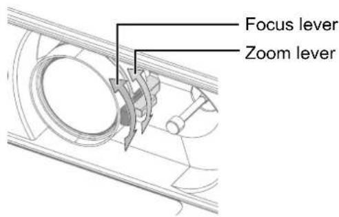
Line drawing of a computer monitor with scroll buttons and ventilation slots (no text or symbols)-
Adjust the focus and the projected image size.
-
Turn the focus lever and zoom lever to adjust the image.
- ● You can confirm the adjusted effect with the TEST PATTERN in OPTION menu. See "TEST PATTERN" on page 43.
NOTE:
- Do not touch the air exhaust port as this may cause burns or injury.
- If keystone distortion occurs, see "KEYSTONE" on page 35.
- If you adjust the focus, you may need to adjust the size of the image by moving the zoom lever again.
Remote control operation
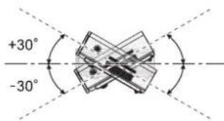
Operating range
(Shown as PT-FW300NTU)
You can operate the projector with the remote control within the remote range 15 m (49'2"), approximately ± 30° vertically and horizontally.
● Facing to the projector
Ensure the remote control emitter is facing to the remote control signal receptor on front/back of the projector and press the required buttons to operate.
● Facing to the screen
Ensure the remote control emitter is facing to the screen and press the required buttons to operate the projector. The signal will be reflected off the screen. The operating range may differ due to the screen material. This function may not be effective with a translucent screen.
NOTE:
- Do not let strong light shine onto the signal receptor. The remote control may malfunction under strong light such as fluorescent.
- If there are any obstacles between the remote control and the remote control signal receptor, the remote control may not operate correctly.
Setting up the image position automatically

You can adjust the setting of SHIFT, DOT CLOCK and CLOCK PHASE in the POSITION menu automatically for the projected COMPUTER signal image.
● With DVI signal, adjust SHIFT setting only.
NOTE:
- If the dot clock frequency is 150 MHz or higher, AUTO SETUP is not effective.
- If the projected image is dark or blurred around the edge, AUTO SETUP may stop the processing before complete. Project a much clearer or lighter image and press the AUTO SETUP button again.
- When there is no signal input and SIGNAL SEARCH in DISPLAY OPTION menu is ON, the auto signal detecting system will start.
Switching the input signal

NETWORK

VIDEO
- The graphical guidance will be displayed on the upper right of the projected image and you can confirm the selected input method which is highlighted in yellow. See "INPUT GUIDE" on page 38.
NOTE:
- If you select an unplugged input method, the guidance will blink on and off several times.
- See "List of compatible signals" on page 52.
• See "Connections" on page 19.
- Pressing the COMPUTER button
COMPUTER1 ▶ COMPUTER2
NOTE:
- Only when the COMPUTER2 SELECT is set to INPUT, the COMPUTER2 is selectable.
● Pressing the NETWORK button
- Only for the network connection operation. See CD-ROM contents for more detailed information.
- Pressing the VIDEO button
VIDEO ◀▶ S-VIDEO
- Pressing the INPUT SELECT button on the projector
COMPUTER1

DVI
NETWORK
▶ COMPUTER2

S-VIDEO
◀VIDEO
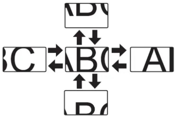
Enlarging the centered area
DIGITAL ZOOM
You can enlarge the projected image down to a centered area for emphasizing within the range of 1x to 2x.

●● Enlarging the image
- Press the DIGITAL ZOOM +/- button once.
- The centered area of the image will then be enlarged to 1.5x.

- Adjust the image size by pressing the DIGITAL ZOOM +/- button.
● ● The image size will be changed in steps of 0.1.

flowchart
graph LR
    A["ABC"] --> B["ABC"]
    B --> C["BC"]
● Shifting the center point
Press ▲ ▼ ◀ ▶ to shift the center point.
flowchart
graph TD
    A["A"] -->|↑↓| B["B"]
    B -->|←| C["C"]
    C -->|↑↓| D["D"]
    D -->|←| A
    A -->|↑↓| B
    B -->|←| C
    C -->|↑↓| D
    D -->|↑↓| A
NOTE:
- When the COMPUTER signal is projected, the enlargement range will be changed to 1x to 3x. When the FRAME LOCK in POSITION menu is set to ON, the enlargement range is 1x to 2x. See “FRAME LOCK” on page 37.
- When the input signal is changed while the DIGITAL ZOOM is activated, the DIGITAL ZOOM will be cancelled.
- While DIGITAL ZOOM is activated, FREEZE is not available.
Capturing an image

Press the FREEZE button to capture the image and stop the audio, and you can see it as a still picture while the AV equipment are continuing.
Press the FREEZE button again to escape and return to the continuing image.
Stopping the projection

You can stop the projection and audio sound through the projector for saving electrical
power. Press the AV MUTE button again to escape.
Resetting to the factory default settings

You can reset most of the customized settings to the factory defaults by pressing the DEFAULT button of the remote control. Display the required sub menu or the menu items, and press the DEFAULT button again.
- See "Main menu and Sub-menu" on page 30.
NOTE:
- Some menu items are not available to reset by pressing the DEFAULT button. Adjust each menu items manually.
- To reset all the settings to the factory defaults, see "INITIAL START UP" on page 41.
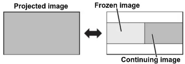
Projecting an image in INDEX-WINDOW mode
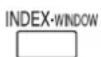
You can project an image in split 2 windows as an INDEX-WINDOW, one is frozen, stored in memory and displayed on the screen's left side, while the display of subsequent images continues on the right.
To escape from the INDEX-WINDOW, press the MENU or RETURN button.
● Switching the position
In default, the frozen image is displayed on the left and the subsequent image is displayed on the right. Press ◀▶ to switch the position.
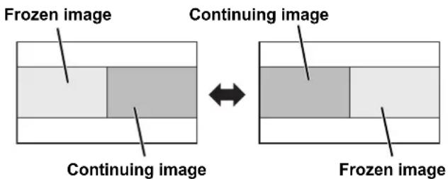
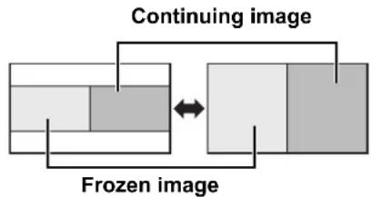
● Changing the image size
Press ▲ ▼ to capture a new image and change the size in 2 ways.
flowchart
graph LR
    A["Frozen image"] --> B["Continuing image"]
    B <--> C["Continuing image"]
NOTE:
- If you change the window size, the aspect ratio of the image is changed and becomes vertically elongated.
- When vertically enlarged, some signals image with THROUGH aspect ratio setting will not be displayed correctly.
● Capturing a new image
While in INDEX-WINDOW mode, press the ENTER button to capture a new image and the frozen image window will be updated in a while.
NOTE:
- When capturing a quick moving picture, perform several times to get a stabled image.
Using an assigned function
You can assign a selected function to the FUNCTION button. Following functions are assignable.
| Options Functions Refer | ||
| DISABLE | Deactivate the FUNCTION button. | - |
| ASPECT Display the ASPECT menu. 36 | ||
| PICTURE MODE | Display the PICTURE MODE menu. | 33 |
| DAYLIGHT VIEW | Display the DAYLIGHT VIEW menu. | 34 |
| CLOSED CAPTION | Press to turn on/off the CLOSED CAPTION. | 38 |
NOTE: • See "FUNCTION BUTTON" on page 42.
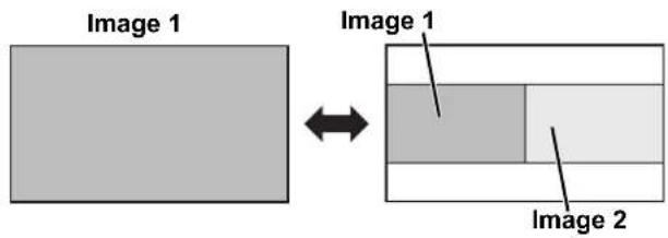
Projecting 2 different source image at a time

You can project the image and another source of image at the same time in double window style. Press any button of RETURN, MENU, SIDE BY SIDE or INPUT SELECT buttons to return to the normal projection style.
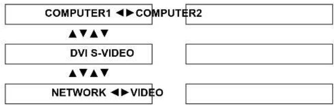
● Switching the signal
In default, the first image is displayed on the left and the second image is displayed on the right. You can switch and cycle through the signals of the second image by pressing ▲ ▼
flowchart
graph TD
    A["COMPUTER1 ◀▶ COMPUTER2"] --> B["▲▼▲▼"]
    C["DVI S-VIDEO"] --> D["▲▼▲▼"]
    E["NETWORK ◀▶ VIDEO"] --> F[" "]
    G[" "] --> H[" "]
Side by Side function signal combination table
| Image 1 | |||||||||||
| COMPUTER1 COM | MPUTER2 | VIDEO IN | S-VIDEO IN | DVI-D | NETWORK connection | ||||||
| Still | Movie | Still | Movie | Still | Movie | ||||||
| Image 2 | COMPUTER1 | Still | N/A | N/A | OK | OK | OK | OK | OK | OK | OK |
| Movie | N/A | N/A | OK | N/A | N/A | N/A | OK | N/A | OK | ||
| COMPUTER2 | Still | OK | OK | N/A | N/A | OK | OK | OK | OK | OK | |
| Movie | OK | N/A | N/A | N/A | N/A | N/A | OK | N/A | OK | ||
| VIDEO IN | OK | N/A | OK | N/A | N/A | N/A | OK | N/A | OK | ||
| S-VIDEO IN | OK | N/A | OK | N/A | N/A | N/A | OK | N/A | OK | ||
| DVI-D | Still | OK | OK | OK | OK | OK | OK | N/A | N/A | OK | |
| Movie | OK | N/A | OK | N/A | N/A | N/A | N/A | N/A | OK | ||
| NETWORK connection | OK | OK | OK | OK | OK | OK | OK | OK | N/A | ||
NOTE:
- FREEZE and VOLUME controls are available with the first image only.
- While SIDE BY SIDE is activated, DIGITAL ZOOM, INDEX-WINDOW and AUTO SETUP are not available.
- While SIDE BY SIDE is activated, the main menu will not be displayed.
- The second image will apply to the value of the PICTURE settings of the first image except CONTRAST and BRIGHTNESS.
• COMPUTER and NETWORK signals will not keep the adjusted aspect ratio.
Using the laser pointer

You can highlight items on the screen with the red laser pointer while projecting the image in presentations or visual demonstrations as an eye-catching pointing device.
Hold down the LASER button to go on the laser pointer and release to go off.
- Top view

Laser pointer beam emitter
- Deactivating switch
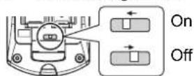
- Disable the LASER button
You can disable the LASER button for an accidental operation.
- Open the battery compartment cover of the remote control.
- Slide the switch tab.
- Close the battery compartment cover of the remote control.
● ● See "Battery compartment" on page 14.
NOTE:
- If you press the disabled LASER button, the alert "LASER POINTER IS DISABLED." will be displayed on the screen. While the menu is displaying, the alert will not be displayed.
● ● Cautions
(Shown as PT-FW300NTU)
CAUTION: Use of controls of adjustments or performance of procedures other than those specified herein may result in hazardous radiation exposure.
NOTE:
• The laser pointer should never be projected directly into the eyes of a person or animal.
- Do not aim the laser at reflective surfaces.
- Do not allow children to use laser pointer.
- Never look directly into the laser beam.
- The laser pointer is not effective with translucent screens.
- Please read the cautions on the remote control.
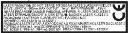
• This is a Class 2 laser product.
Controlling the volume of the speaker

You can control the volume of the built-in speakers and output sound. Press "+" side of the VOLUME button to increase and "-" to decrease.
NOTE:
- Power consumption can be reduced if the volume level is lowered.
Menu Navigation
Main menu and Sub-menu
The menu options are structured and categorized. You can navigate through the menu with ▲ ▼ ◀ ▶ buttons. See "Menu Navigation" on page 30.
● ● The underlined items are factory default settings.
- Some default settings vary by the selected input signal.
- Sub-menu items vary according to the selected input signal.
- Some settings are adjustable without any signals.

PICTURE
PICTURE MODE page 33
NATURAL STANDARD
DYNAMIC BLACKBOARD
CINEMA
CONTRAST page 33
(Default: 0)
BRIGHTNESS page 33
(Default: 0)
COLOR page 33
(Not available with NETWORK connection)
(Default: 0)
TINT page 33
(Not available with NETWORK connection)
(Default: 0)
SHARPNESS page 33
(Default: 0)
WHITE BALANCE RED ^*1 page 33
(Default: 0)
WHITE BALANCE GREEN ^*1 page 33
(Default: 0)
WHITE BALANCE BLUE ^*1 page 33
(Default: 0)
COLOR TEMPERATURE page 34
DEFAULT
LOW HIGH
DAYLIGHT VIEW page 34
AUTO
OFF
ON
DIGITAL CINEMA REALITY page 34
ON
OFF
NOISE REDUCTION page 34
OFF
ON
TV-SYSTEM page 34
AUTO
NTSC
NTSC 4.43
PAL
PAL-M
PAL-N
SECAM
RGB/YP _B PR page 34
AUTO
RGB
YPBPR

POSITION
KEYSTONE page 35
(Default: 0)
SHIFT page 35
(Not available with NETWORK connection)
H (Default: 0) V (Default: 0)
SHIFT V page 35
(Available with NETWORK connection only)
(Default: 0)
DOT CLOCK page 35
(Signals from COMPUTER only)
(Default: 0)
CLOCK PHASE page 35
(Signals from COMPUTER only)
(Default: 0)
OVER SCAN page 35
(Not available with NETWORK connection)
ASPECT page 36
AUTO 4:3 16:9 H-FIT
V-FIT HV-FIT THROUGH
FRAME LOCK page 37
(Signals from COMPUTER only)
OFF ON

LANGUAGE
DEUTSCH POLSKI
FRANÇAIS ČEŠTINA
ESPAÑOL MAGYAR
ITALIANO PYCCKIЙ
PORTUGUÊS ไทย
SVENSKA 한국어
NORSK ENGLISH
DANSK 中文
日本語

DISPLAY OPTION
ON-SCREEN DISPLAY page 38
INPUT GUIDE
DETAILED SIMPLE
OFF
OSD DESIGN
TYPE1 TYPE2
TYPE3
WARNING MESSAGE
ON OFF
DVI-D IN page 38
DVI EDID
EDID1 EDID2(PC)
DVI SIGNAL LEVEL
0-255:PC 16-235
CLOSED CAPTION SETTING page 38
CLOSED CAPTION
OFF ON
MODE
CC1 CC2 CC3 CC4
SCREEN SETTING page 38
SCREEN FORMAT
16:10 16:9
SCREEN POSITION
CENTER LOW
HIGH
STARTUP LOGO page 39
ON OFF USER
AUTO SETUP page 39
AUTO BUTTON
SIGNAL SEARCH page 39
ON OFF
BACK COLOR page 39
BLUE BLACK
WIDE MODE page 39
AUTO OFF
ON
SXGA MODE page 39
SXGA SXGA+
OTHER FUNCTIONS page 40
AUTO SETUP FREEZE
15 MIN. 20 MIN. 25 MIN. 30 MIN.
35 MIN. 40 MIN. 45 MIN. 50 MIN.
55 MIN. 60 MIN.
INITIAL START UP page 41
WIRELESS LAN (PT-FW300NTU only)
NAME CHANGE PASSWORD
PASSWORD CHANGE
NETWORK STANDBY
NETWORK CONTROL
LIVE MODE CUT IN
COMPUTER SEARCH
MULTI-LIVE STATUS
INITIALIZE
See CD-ROM contents for more detailed information.
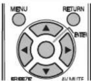
Navigating through the menu
● Displaying the Main menu
MENU

Press the MENU button to display the main menu and the operating guidance.
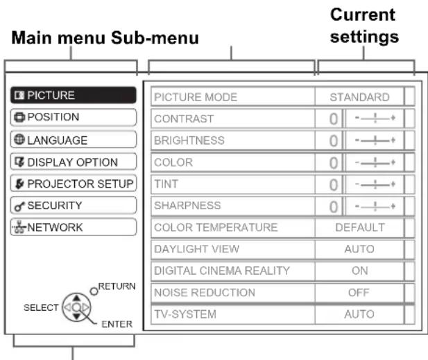
Operating guidance
Contains the required buttons to adjust the settings.
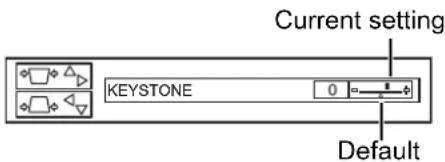
- Adjusting with the bar scale items
The triangle mark under the bar indicates factory default setting and the square indicates the current setting.
● Returning to the previous menu
RETURN

Press the MENU or RETURN button to return to the previous menu. Press repeatedly to escape from the menu mode and return to the projection.
● Operating procedure
- Press ▲ ▼ to scroll to the required main menu item and press the ENTER button to select.
● ● The selected item is highlighted in orange and the sub-menu is displayed on the right.
- See "Main menu and Sub-menu" on page 30.
-
Press ▲▼ to scroll to the required sub-menu item and press ◀▶ or the ENTER button to adjust.
-
The selected item is called up and the other menu items disappear from the screen. Called up item will be disappear after 5 seconds and return to the menu mode.
- If there is a lower level, the next level will be displayed.
-
Press ◀▶ to adjust or set the selected item.
-
● For items using a bar scale, the current settings are displayed on the left of the bar scale.
- ● You can cycle through the options of an item by pressing ◀ ▶.
- Press the MENU or RETURN button to return to the previous menu.
NOTE:
- See "Resetting to the factory default settings" on page 27 to reset each menu item.
- See "INITIALIZE ALL" on page 43 to reset all the settings.
PICTURE menu
Remote control Control panel

- See "Navigating through the menu" on page 32.
● ● See "Main menu and Sub-menu" on page 30.
PICTURE MODE
Depending on the projection environment, you can use these preset parameter settings to optimise image projection. Press ◀▶ to cycle through the options.
| STANDARD Setting for a general image | |
| DYNAMIC Bright and sharp setting | |
| BLACKBOARD | Setting for when projecting on a blackboard |
| NATURAL^*1 | Reproduces the original color of the image |
| CINEMA^*2 | Setting for a cinema type movie |
*1. Selectable when sill image is displayed.
*2. Selectable when moving image is displayed.
NOTE:
- It may take for a while until the image stabilized in the selected mode.
CONTRAST
You can adjust the contrast of the projected image. Adjust the BRIGHTNESS in advance if necessary.
HigherLower
BRIGHTNESS
You can adjust the brightness of the projected image.
Brighter Darker
COLOR
You can adjust the color saturation of the projected image. (Available with VIDEO/S-VIDEO/YPBPR/RGB movie/DVI movie signals only)
DarkerLighter
TINT
You can adjust the skin tone in the projected image. (Available with VIDEO/S-VIDEO/YPBPR/RGB movie/DVI movie signals only)
More reddish
More greenish
SHARPNESS
You can adjust the sharpness of the projected image.
Less sharp
More sharp
WHITE BALANCE RED
You can adjust the white balance more properly in red color temperature by pressing ◀▶. (Available with RGB/DVI still signals only)
WHITE BALANCE GREEN
You can adjust the white balance more properly in green color temperature by pressing ◀▶. (Available with RGB/DVI still signals only)
WHITE BALANCE BLUE
You can adjust the white balance more properly in blue color temperature by pressing ◀▶. (Available with RGB/DVI still signals only)
COLOR TEMPERATURE
You can adjust the white balance of the projected image.
- LOW More bluish
● ● DEFAULT Balanced white
● ● HIGH More reddish
DAYLIGHT VIEW
You can keep the projected image bright and vivid even in well-lit rooms where the ambient light sources cannot be controlled, such as when a door opens or when window coverings fail to block out sunlight.
● ● AUTO: Automatic adjustment
● ON: Active
- OFF: Deactive
NOTE:
- Do not cover the Ambient Luminance Sensor (ALS) of the projector. See “Ambient Luminance Sensor (ALS)” on page 12.
- AUTO is not available when INSTALLATION setting in OPTION menu is set to REAR/DESK or REAR/CEILING.
DIGITAL CINEMA REALITY
You can improve the vertical resolution of a 2-2 or 2-3 pulldown movie. Press ◀▶ to select the required setting. (Not available with NETWORK signals)
- OFF Deactive
● ON Active
NOTE:
• Available with 480i, 576i, 1 080/60i and 1 080/50i only.
NOISE REDUCTION
You can switch the automatic noise reduction system on/off. Press ◀▶ to select the required setting.
● ON: Automatic noise reduction
● OFF: No noise reduction
NOTE:
- Applying noise reduction may affect image quality.
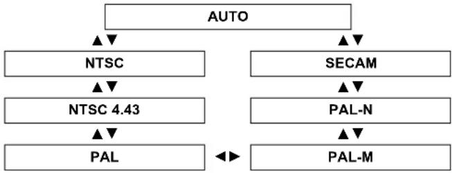
TV-SYSTEM
When the video signal is changed, the setting switches automatically. You can switch the setting manually to match the video data. Press ◀▶ to cycle through the options. (Available with S-VIDEO/VIDEO only)
flowchart
graph TD
    A["AUTO"] --> B["NTSC"]
    A --> C["SECAM"]
    B --> D["NTSC 4.43"]
    C --> E["PAL-N"]
    D --> F["PAL"]
    E --> G["PAL-M"]
    F --> H["◀▶"]
    G --> H
NOTE:
- AUTO setting will select from NTSC/NTSC 4.43/PAL/PAL60/PAL-M/PAL-N/SECAM.
RGB/YPBPR
The projector will detect the signal from the COMPUTER terminals if the signal is RGB or YPBPR. You can turn off the automatic detecting system and switch between
RGB and YPBPR manually.
● ● AUTO: Automatic detecting system
- RGB: Project as RGB signal
● YPBPR: Project as YPBPR signal
NOTE:
• Available with VGA60, 480i, 576i, 480p, 576p, 1 080/60i, 1 080/50i, 720/60p, 720/50p, 1 080/60p, 1 080/50p only.
- When the input signal is not selected correctly with AUTO setting, select RGB or YPBPR manually.
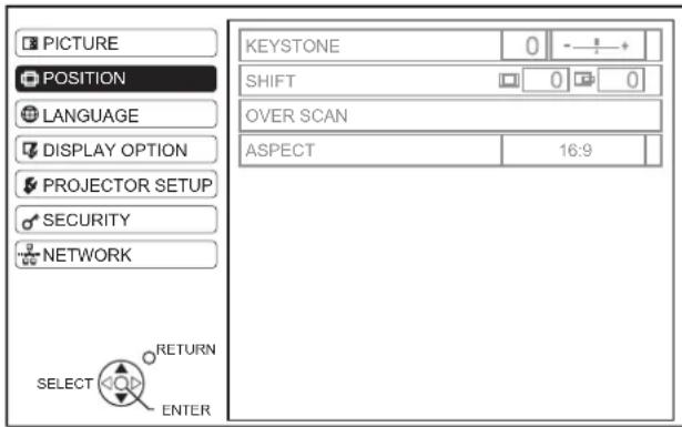
POSITION menu
Remote control Control panel

- See "Navigating through the menu" on page 32.
- See "Main menu and Sub-menu" on page 30.
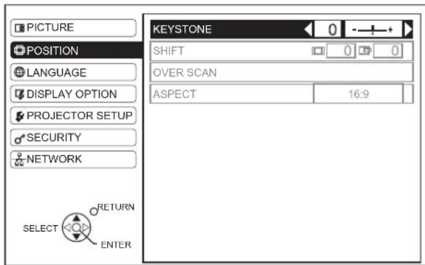
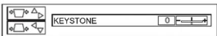
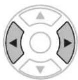
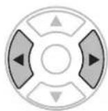
KEYSTONE
If the projector is aligned non-perpendicularly to the screen, or if the projection screen has an angled surface, you can correct keystone.
Image Operation
NOTE:
- You can correct the distortion ± 30 degrees from the plane. For a better quality image, installing the projector with a minimum of distortion is recommended.
- Some distortion may be retained for lens shift adjustment.
- The distortion of the main menu screen is not correctable.
- The result of the keystone correction will affect the aspect ratio and the size of the image.
SHIFT
You can move the projected image for fine adjustment. Press ◀▶ to move horizontally and ▲▼ vertically. (Not available with NETWORK signals)
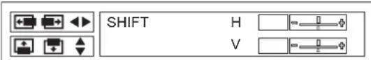
SHIFT V
When H-FIT setting in ASPECT menu is selected, you can move the projected image vertically for fine adjustment by pressing ◀▶. (Available with signals from NETWORK only)
DOT CLOCK
If you have interference patterns of the projected image, which is sometimes referred to as moire or noise, you can minimize it by pressing ◀▶ to adjust the clock frequency. (Available with signals of RGB/DVI still only)

NOTE:
- If the projecting signal's dot clock frequency is higher than 150 MHz, the adjustment may not make a difference.
- DOT CLOCK needs to be adjusted before adjusting the CLOCK PHASE.
CLOCK PHASE
If you require further adjustment for the same reason as the DOT CLOCK adjustment, you can fine adjust the timing of the clock. Press ◀▶ to adjust. (Available with signals of RGB/DVI still only)
NOTE:
- If the projecting signal's dot clock frequency is higher than 150 MHz, the adjustment may not make a difference.
OVER SCAN
If the 4 edges of an image is partly dropped, you can use this function to adjust and project it properly. (Not available with signals of NETWORK)
● ● ◀ Shrink
● ● ▶Enlarge
ASPECT
You can switch the aspect ratio manually when needed. Press ◀▶ to cycle through the options.
■ Aspect ratio options
AUTO
Signals which contains an identifying aspect signal will be detected and automatically project the image in proper ratio. (NTSC and 525i (480i) signals only)
4:3
When a 4:3 or 5:4 signal is detected, the image will be projected without any change, and other signals will be adjusted to 4:3 with preserving original ratio.
flowchart
graph TD
    A["Square Block 1"] --> B["Rectangular Block 1"]
    C["Square Block 2"] --> D["Rectangular Block 2"]
16:9
When a 16:10, 16:9 or 15:9 signal is detected, the image will be projected without any change, and other signals will be adjusted to 16:9.
flowchart
graph TD
    A["Block 1"] --> B["Block 2"]
    B --> C["Block 3"]
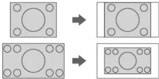
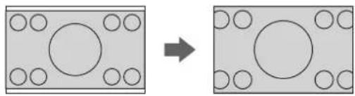
H-FIT
The 4:3/5:4 image will be stretched to the horizontal limit of the SCREEN FORMAT setting size with preserving original ratio and the vertical edge will be cropped.
natural_image
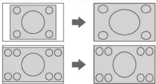
Two square diagrams showing a circular component before and after transformation, with no text or symbols present.V-FIT
The 16:9 (16:10)/15:9 image will be stretched to the vertical limit of the SCREEN FORMAT setting size with preserving original ratio and the horizontal edge will be cropped.
natural_image
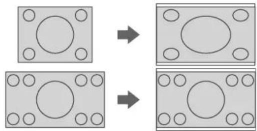
Diagram showing transformation of a rectangular block with circular holes to a larger rectangular block with circles (no text or symbols)HV-FIT
The image will be stretched to the vertical and horizontal limit of the SCREEN FORMAT setting size without preserving original ratio and the vertical and horizontal edge will not be cropped.
flowchart
graph TD
    A["Square with circles"] --> B["Circle with circles"]
    C["Square with circles"] --> D["Circle with circles"]
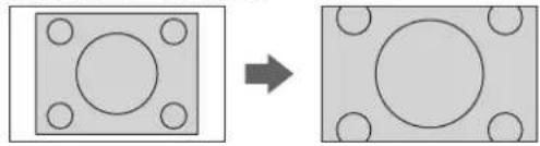
● THROUGH
The image will be projected without any size adjustment.
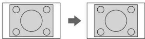
natural_image
Two square panels with circular holes and a right-pointing arrow, no text or symbols present.- Menu items displaying pattern depends on signals
| Signals | SCREEN FORMAT menu setting (See page 38) | |
| 16:10 16:9 | ||
| VIDEO/S-VIDEO/YPBPR | 4:3 ◀▶ 16:9 ◀▶ H-FIT ◀▶ HV-FIT ◀▶ THROUGH | 4:3 ◀▶ H-FIT ◀▶ HV-FIT ◀▶ THROUGH |
| NTSC | AUTO ◀▶ 4:3 ◀▶ 16:9 ◀▶ H-FIT ◀▶ HV-FIT ◀▶ THROUGH | AUTO ◀▶ 4:3 ◀▶ H-FIT ◀▶ HV-FIT ◀▶ THROUGH |
| 1 080/50i, 1 080/60i, 720/50p, 720/60p, 1 080/60p, 1 080/50p | 16:9 ◀▶ V-FIT ◀▶ HV-FIT ◀▶ 4:3 | Not available |
| COMPUTER | 4:3 ◀▶ 16:9 ◀▶ H-FIT ◀▶ HV-FIT ◀▶ THROUGH | 4:3 ◀▶ H-FIT ◀▶ HV-FIT |
| COMPUTERWXGA768, WIDE720, 1 080/60p, 1 080/50p | 16:9 ◀▶ V-FIT ◀▶ HV-FIT ◀▶ 4:3 | 4:3 ◀▶ HV-FIT |
| WIDE signals exceptWXGA768, WIDE720, 1 080/60p, 1 080/50p | 16:9 ◀▶ 4:3 | 4:3 ◀▶ HV-FIT |
NOTE:
- If you project an image with an unmatched aspect ratio, the image may distort or some portions may be cropped. Select an aspect ratio which preserves the intention of the image creator.
- The order of ASPECT types is defined not only by the input method but also by the input signals. See “List of compatible signals” on page 52.
- If you project a copyrighted image enlarged or distorted by using ASPECT function in commercial use in a public place, such as a restaurant or hotel, you might infringe on the copyright of the creator which is protected by copyright law.
- Selectable aspect ratio options vary according to input signals.
FRAME LOCK
If the projected image is degraded, you can activate FRAME LOCK for synchronisation. Press ◀▶ to select the required option. (Available with RGB/DVI signals only)
- OFF Deactive
● ON Active
DISPLAY OPTION menu
Remote control
Control panel
● ● See "Navigating through the menu" on page 32.
● See "Main menu and Sub-menu" on page 30.
ON-SCREEN DISPLAY
- INPUT GUIDE
When you change the input method, the guidance appears in the upper right corner of the screen. The following display methods are available. Press
◀▶ to cycle through the options.
| Options | Function |
| DETAILED | Display the input method by graphic. The INPUT GUIDE will go out after 3 seconds without any operation. If you select any COMPUTER or DVI terminal which has no signal, the computer connection guidance will be displayed. See “Computer connection guidance” on page 54. |
| SIMPLE | Display the input method by text. The INPUT GUIDE will go out after 3 seconds without any operation. |
| OFF | Turn off the guidance. |
- OSD DESIGN
You can change the background color of the menu.
Press ◀▶ to select the required option.
| TYPE1 | Semi transparent black |
| TYPE2 | Solid blue |
| TYPE3 | Semi transparent dark blue |
● WARNING MESSAGE
You can let display only the minimum warning messages and hide others.
● ● ON All of the warning messages will be displayed.
- OFF Only the minimum warning messages will be displayed.
NOTE:
- When the WARNING MESSAGE is set to OFF, use the projector with utmost care due to the most of warning messages will not be displayed.
DVI-D IN
NOTE:
- The DVI-D IN setting for the best quality depends on the output equipment. Refer the instructions of the connected equipment.
- DVI signal is very sensitive, and malfunction may occur or other problems could be encountered with some DVI equipment.
• DVI EDID
You can switch the EDID setting and signal level for variable DVI signals.
● EDID1 480p, 576p, 1 080/60i, 1 080/50i, 720/60p, 720/50p, 1 080/60p, 1 080/50p
● ● EDID2(PC) VGA60, SVGA60, XGA60, XGA70, XGA75, WXGA768/60, SXGA60, SXGA60+, WXGA800/60
● DVI SIGNAL LEVEL
● ● 0-255:PC (PC scale) For connecting to a computer via DVI-D IN terminal.
● ● 16-235 (TV scale) For connecting to AV equipment via DVI-D IN terminal, such as DVI - HDMI connection.
CLOSED CAPTION
SETTING
If the input signal contains closed captions, you can turn on the feature and switch the channels.
CLOSED CAPTION
- OFF Deactive
● ON Active
MODE
● CC1 - 4 Change the channels CC1 - 4
NOTE:
- VCR with TBC (Time Base Corrector) function is recommended for video cassette tapes.
SCREEN SETTING
- SCREEN FORMAT
Select the required screen format by pressing
◀ ▶
● ● 16:10 When project on a 16:10 or 4:3 screen.
● ● 16:9 When project on a 16:9 screen.
● SCREEN POSITION
You can change the displaying position of the menu. When SCREEN FORMAT is set to 16:10, you can change the displaying position of the menu. Press ◀▶ to select the required option.
- ● LOW Displays the menu in the lower part of the screen.
- ● CENTER Displays the menu in the middle of the screen.
● ● HIGH Displays the menu in the upper part of the screen.
STARTUP LOGO
You can switch the logo on/off that is displayed when starting up the projector. Press ◀▶ to select the required option. STARTUP LOGO will be displayed for 30 seconds.
● ON Active
- OFF Deactive
- ● USER Display the original text
● Editing the original text
If you select USER, you can display the 2 lines of original text up to 40 characters in 1 line instead of the logo.
![TEXT CHANGE A B C D E F G H I J K L M N O P Q R S T U V W X Y Z a b c d e f g h i j k l m n o p q r s t u v w x y z 0 1 2 3 4 5 6 7 8 9 SPACE ! " # $ % & ' * + - / = ? @ \ ^ _ ` | ~ ( ) < > [ ] { } , . : ; OK CANCEL](/content/2026/03/528149/images/4e953a40141b3d33bec44e1e957ef75a4521bd4213d86fecf714d3da604e8b14.jpg)
- Select USER and press ENTER.
-
Select the required line to enter or edit the original text, and press the ENTER button.
-
Enter the characters and repeat until finish the line.
-
Use ▲ ▼ ◀▶ to specify the location of the required character, and press the ENTER button.
- Move the cursor to ALL DELETE and press the ENTER button to delete all the entered text line.
- Press the DEFAULT button to delete the last entered character or indicated with the cursor in the text line.
-
● To insert a character in the entered text line, move the cursor to the text box to select the required place and press ▼ to select a character.
-
Select OK and press the ENTER button to set the entered text in a box.
- Press ▼ and edit the TEXT2 if you need to, and repeat the step 3.
AUTO SETUP
You can turn off the AUTO SETUP button function for when the COMPUTER signal is detected.
● ● AUTO When the projector detects a COMPUTER or DVI signal, adjust the projected image position automatically for SHIFT, SIGNAL SEARCH, DOT CLOCK and CLOCK PHASE.
- BUTTON Only when the AUTO SETUP button is pressed, the projected image position will be adjusted for DOT CLOCK and CLOCK PHASE. See "Remote control" on page 14.
NOTE:
• Usually the recommended setting is AUTO.
SIGNAL SEARCH
You can turn off the auto signal detecting system.
- ON Detect the input signal from the terminals and project the image.
- OFF Deactive
NOTE:
- SIGNAL SEARCH is not available when any input signal is projecting.
• Usually the recommended setting is ON.
BACK COLOR
You can choose a BLUE or BLACK screen for when the projector is idle. Press ◀▶ to select the required option.
WIDE MODE
When projecting WIDE signals, switch to ON to display the image in well adjusted size.
● AUTO Automatic detective system
● OFF For 4:3 signals
● ON For WIDE signals
(16:9, 16:10 and 15:9)
SXGA MODE
You can switch the projection mode between SXGA+ and SXGA for SXGA signals. Press ◀▶ to select the required option.
● ● SXGA Smaller setting
● ● SXGA+ Larger setting
OTHER FUNCTIONS
From menu operation, you can apply to the functions, which are only for the remote control.
| Menu items Refer | |
| AUTO SETUP See page 25. | |
| FREEZE See page 27. | |
| AV MUTE See page 27. | |
| SIDE BY SIDE See page 28. | |
| INDEX-WINDOW See page 27. | |
| DIGITAL ZOOM | You can enlarge the projected image. Press ◀▶ to adjust the size, and press the ENTER button.Press the RETURN button to return to the normal projection. |
PROJECTOR SETUP menu
Remote control Control panel
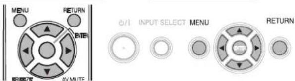
- See "Navigating through the menu" on page 32.
- See "Main menu and Sub-menu" on page 30.
STATUS
You can see the status of the projector about the following items.
Items Description
● SIGNAL
NAME Projecting signal name
FREQUENCY Projecting signal frequency
● RUNTIME
PROJECTOR Duration of projector used time
LAMP Duration of lamp used time
● REMAINING FILTER
QUANTITY Quantity of filter remaining
COMPUTER2 SELECT
You can switch the function of the COMPUTER2 IN/1 OUT terminal.
● ● INPUT COMPUTER2 IN
● ● OUTPUT COMPUTER1 OUT
NO SIGNAL SHUT-OFF
You can set the timer to switch off the power of the projector after a certain period of time automatically when no signal is detected. Press ◀▶ to select the required period from 15 to 60 minutes at intervals of 5 minutes.
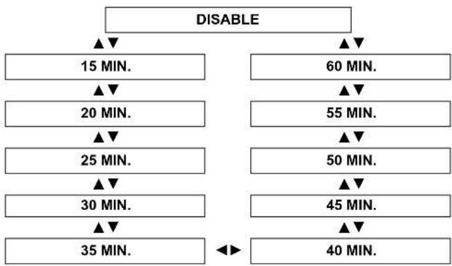
flowchart
graph TD
    A["DISABLE"] --> B["15 MIN."]
    A --> C["60 MIN."]
    B --> D["20 MIN."]
    C --> E["55 MIN."]
    D --> F["25 MIN."]
    E --> G["50 MIN."]
    F --> H["30 MIN."]
    G --> I["45 MIN."]
    H --> J["35 MIN."]
    I --> K["40 MIN."]
    J --> L["◀"]
    K --> L
INITIAL START UP
You can select how the projector start when the power cord is connected.
| Options Description | |
| LAST MEMORY | Start as the same mode as the last switched off. |
| STANDBY | Always start in standby mode. |
| ON | Always start in projecting mode. |
INSTALLATION
When installing the projector, select the projection method according to the projector position. Press ◀▶ to cycle through the options. See “Projection method” on page 16.
| FRONT/DESK | Setting on a desk/floor and projecting from front |
| FRONT/CEILING | Mounting on the ceiling and projecting from front |
| REAR/DESK | Setting on a desk/floor and projecting from rear |
| REAR/CEILING | Mounting on the ceiling and projecting from rear |
HIGH ALTITUDE MODE
If you use the projector at high elevation, the HIGH ALTITUDE MODE setting needs to be ON to set the fan speed high. Press ◀▶ to select the required option.
- OFF The fan speed is low.
● ON The fan speed is high.
NOTE:
- At 1 400 m (4 593 ft) above sea level, the setting must be ON.
- The loudness of fan noise depends on the HIGH ALTITUDE MODE setting.
EMULATE
You can switch to the Panasonic past model's control commands for COMPUTER connection.
| DEFAULT | F100, FW100, F200, F300, FW300 models |
| D3500 D3500 models | |
| D4000 D4000 models | |
| D/W5K series | D5500, DW5000, D5600, DW5100, D5700 models |
| L730 L520, L720 models | |
| L780 L750, L780 models | |
| L735 L735 models | |
| L785 L785 models | |
| LB/W80 LB75, LB80, LW80 models | |
FUNCTION BUTTON
You can assign a certain menu function to the FUNCTION button as shortcut. Press ◀▶ to select the required menu option, and the ENTER button.
| Options Functions | Refer | |
| DISABLE | Deactivate the FUNCTION button. | - |
| ASPECT | Display the ASPECT menu. | 36 |
| PICTURE MODE | Display the PICTURE MODE menu. | 33 |
| DAYLIGHT VIEW | Display the DAYLIGHT VIEW menu. | 34 |
| CLOSED CAPTION | Press to turn on/off the CLOSED CAPTION. | 38 |
NOTE:
- Without any operation for 5 seconds, the displayed menu will be disappeared.
AUDIO SETTING
● VOLUME
You can adjust the volume of the built-in monaural speaker and VARIABLE AUDIO OUT terminal.
● ● ▲ Decrease
- ●▶ Increase
● BALANCE
You can adjust to hear the sound played equally through both right and left from VARIABLE AUDIO OUT, or shift the balance so more sound plays through the left or right side.
● ● ◀ More sound plays through the left side
● ●▶ More sound plays through the right side
● IN STANDBY MODE
You can switch on/off the sound output in standby mode.
- OFF No sound in standby mode.
● ● ON Output audio in standby mode.
● AUDIO IN SELECT
You can switch the audio output method for COMPUTER1 IN, COMPUTER2 IN and DVI-D IN terminals.
● DVI
● COM.AUDIO IN 2
Output audio that is input to the COMPUTER AUDIO 2.
● ● AUDIO IN Output audio that is input to the AUDIO IN.
● COMPUTER1
● COM.AUDIO IN 1
Output audio that is input to the COMPUTER AUDIO 1.
● ● AUDIO IN Output audio that is input to the AUDIO IN.
● COMPUTER2
● COM.AUDIO IN 2
Output audio that is input to the COMPUTER AUDIO 2.
● ● AUDIO IN Output audio that is input to the AUDIO IN.
TEST PATTERN
You can use the 7 different test patterns to adjust the focus of the image. See "Lens shift and positioning" on page 17.
- Press the ENTER button to display the test pattern 1.
- Press ◀▶ to select the required test pattern.
- Adjust the focus with the focus lever.
- Press the MENU or RETURN button to return to the previous menu, or press repeatedly to escape from the menu mode.
NOTE:
- When the projector and/or the screen is tilted, adjust the focus at the center of the image. The upper and lower edge might be out of focus.
- When the image is distorted in keystone, adjust the KEYSTONE in POSITION menu.
INITIALIZE ALL
You can reset all of the customized settings to the factory defaults except NETWORK, RUNTIME and REMAINING FILTER of STATUS in PROJECTOR SETUP menu.
- Press the ENTER button.
- Select OK by pressing ◀, then press the ENTER button.
- Turn off the power by pressing the power button.
- Switch off the MAIN POWER button to reset the projector.
- Switch on the MAIN POWER button.
- Press the power button.
- The minimum required setting screen will be displayed.
- See "Minimum required setting screen" on page 11.
NOTE:
- The security system is deactivated by default and when initialized.
- When the projector is initialized, it will be reset to the factory default password operation.
FILTER COUNTER RESET
After you replaced the Auto Cleaning Filter (ACF), REMAINING FILTER of STATUS in PROJECTOR SETUP need to be reset to "0".
- Press the ENTER button for more than 3 seconds. ● ● The confirmation screen will be displayed.
- Select OK by pressing ◀, then press the ENTER button.
- Display the STATUS and confirm the figure.
SECURITY menu
Remote control Control panel
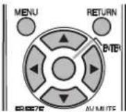
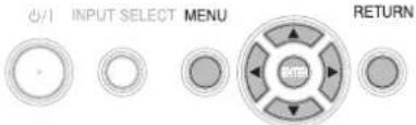
● ● See "Navigating through the menu" on page 32.
● ● See "Main menu and Sub-menu" on page 30.
● Entering the SECURITY menu
Every time when you apply to the SECURITY menu, you will be asked to perform the password operation.
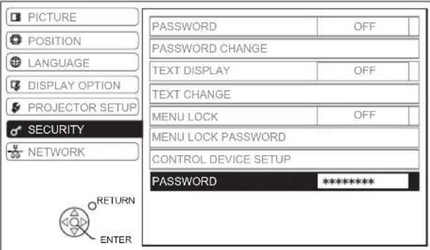
When you apply to the SECURITY menu before you change the password to your original, perform to input the following factory default password operation.
- Press ▲▶▼◀▲▶▼◀ and the ENTER button.
● After you change the password
When you apply to the SECURITY menu after you change the password to your original in the PASSWORD CHANGE menu, input the original password operation.
NOTE:
- The factory default password is valid until you change the password in PASSWORD CHANGE menu.
- The entered password operations will appear as asterisks in the box.
PASSWORD
You can activate the security system and the password operation will be asked to perform when the projecting mode started. Unless you perform the correct password operation, all of the button controls will be disabled except the power button.
- OFF Deactive
● ON Active
NOTE:
- When you activated the security system, make sure to change the password to your original for safety.
- The factory default password is valid until you change the password in PASSWORD CHANGE menu.
PASSWORD CHANGE
You can change the password operation to your original.
- Press a series of button operation up to 8 as a password by using ▲ ▼ ◀ and ▶.
- Press the ENTER button.
- Press the exact same series of button operation you entered in the NEW password box for confirmation.
- If a series of button operation is incorrect, you will be asked to perform again.
- Press the ENTER button.
NOTE:
- The entered password operations will appear as asterisks in the box.
TEXT DISPLAY
You can set your original text, such as company name or URL information, to display regularly at the bottom of the projected image while projecting.
- OFF Deactive
● ON Active
TEXT CHANGE
You can enter your original text up to 22 characters for TEXT DISPLAY.
![TEXT CHANGE A B C D E F G H I J K L M N O P Q R S T U V W X Y Z a b c d e f g h i j k l m n o p q r s t u v w x y z 0 1 2 3 4 5 6 7 8 9 SPACE ! " # $ % & ' * + - / = ? @ \ ^ _ ` | ~ ( ) < > [ ] { } , . : ; ALL DELETE OK CANCEL](/content/2026/03/528149/images/fb0aa020637dfe93c8eed5599480f8bfcca1f129f47eaa471d91b2d96fd07db4.jpg)
-
Enter your original text.
-
Use ▲ ▼ ◀▶ to specify the location of the required character.
- Move the cursor to ALL DELETE and press the ENTER button to delete all the entered text line.
-
Press the DEFAULT button to delete the last entered character or indicated with the cursor in the text line.
● ● To insert a character in the entered text line, move the cursor to the text box to select the required place and press ▼ then perform step 2. -
Press the ENTER button.
● ● The selected character will be displayed in the TEXT CHANGE box. - Repeat until finish your original text.
- Select OK and press the ENTER button to set the entered text.
- Select CANCEL or press the MENU/RETURN buttons to return to the previous menu.
MENU LOCK
You can lock the MENU button function and the password will be asked to display the menu every time.
- OFF
Deactivate the MENU LOCK system.
• ON
Activate the MENU LOCK system.
NOTE:
- The factory default password is "AAAA".
- The factory default password is valid until you change the password in MENU LOCK PASSWORD menu.
- When the projector is initialized, the password will be changed to the factory default setting, "AAAA".
MENU LOCK PASSWORD
You can change the password for MENU LOCK system to your original.
- Press the ENTER button.
- Enter the original password.
- Use ▲ ▼ ◀▶ to specify the location of the required character, and press the ENTER button.
![MENU LOCK PASSWORD A B C D E F G H I J K L M N O P Q R S T U V W X Y Z a b c d e f g h i j k l m n o p q r s t u v w x y z 0 1 2 3 4 5 6 7 8 9 SPACE ! " # $ % & ' * + - / = ? @ \ ^ _ ` | ~ ( ) < > [ ] { } , . : ; OK CANCEL](/content/2026/03/528149/images/1a63c38791919c3c29f88f687cfc5d252c241f015e4a4cf9c25838aebb549758.jpg)
- Repeat step 2 until you finish the text line.
● ● You can enter up to 16 characters.
- Move the cursor to ALL DELETE and press the ENTER button to delete all the entered text line.
- Press the DEFAULT button to delete the last entered character or indicated with the cursor in the text line.
- ● To insert a character in the entered text line, move the cursor to the text box to select the required place and press ▼ then perform step 2.
- Select OK and press the ENTER button to set the password.
NOTE:
- If you need to restore the factory default password, contact to an Authorized Service Center.
CONTROL DEVICE SETUP
NOTE:
- If you disable both of the control panel and remote control buttons, you cannot return to the standby mode. Use this function with utmost care.
- If you press a disabled button, you will be asked to perform the security password operation. The password screen will disappear after 10 seconds without any operation.
● CONTROL PANEL
You can disable the control panel buttons on the projector body. Press ◀ or ▶ to switch the option.
- ENABLE Enable the control panel buttons.
- DISABLE Disable the control panel buttons.
The confirmation screen will be displayed. Select OK by pressing the
◀, and the ENTER button.
NOTE:
- You can enable the disabled control panel buttons by performing the control panel button operation. While pressing the ENTER button, press the MENU button for 2 seconds.
● REMOTE CONTROLLER
You can disable the remote control buttons. Press
◀ or ▶ to switch the option.
- ENABLE Enable the remote control buttons.
● ● DISABLE Disable the remote control buttons.
The confirmation screen will be displayed. Select OK by pressing the
◀, and the ENTER button.
NETWORK menu
Remote control Control panel
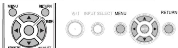
- See "Navigating through the menu" on page 32.
- See "Main menu and Sub-menu" on page 30.
NOTE:
- See more detailed instructions in the contents of the CD-ROM which is provided with the projector.
Items in NETWORK menu
In NETWORK menu, the following items are available.
● ● WIRED LAN
● WIRELESS LAN (PT-FW300NTU only)
● NAME CHANGE
- PASSWORD
● ● PASSWORD CHANGE
● ● NETWORK STANDBY
● ● NETWORK CONTROL
● ● LIVE MODE CUT IN
● ● COMPUTER SEARCH
● ● MULTI-LIVE
- STATUS
- INITIALIZE
NOTE:
- When you activated the security system in SECURITY menu, you need to perform the security password operation to initialize network settings.
TEMP, LAMP and FILTER Indicators
Managing the indicated problems
If a problem should occur with the projector, the TEMP, LAMP and/or FILTER indicators will inform you. Manage the indicated problems as follow.
- Confirm the status of all indicators and projector, and switch off the projector in proper way.
- Find out the cause of the problem by status of the TEMP, LAMP and/or FILTER indicators.
- Follow the instruction for each indication below and solve the problem.
- Turn on the projector in the correct way and confirm the indicator is not indicating a problem any longer.
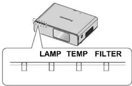
NOTE:
- If no problem is found or the problem remains, do not turn on the projector. Instead contact an Authorized Service Center.
● LAMP indicator
| Indicator | ● Illuminating red ● Flashing red | |||
| Problem | RUNTIME of STATUS in the PROJECTOR SETUP menu has reached 5 000 hours. | LAMP circuit failure, abnormal function or lamp unit is damaged. | ||
| Cause | Lamp unit will run out soon and needs to be replaced. | The MAIN POWER is switched on again before the lamp unit is cooled enough. | Lamp circuit failure, abnormal function. | Lamp unit is damaged. |
| Remedy | See “Replacing the Lamp unit” on page 48. | Let the lamp unit cool down and turn on the MAIN POWER after 90 seconds. | Contact an Authorized Service Center. | See “Replacing the Lamp unit” on page 48. |
- TEMP indicator
| Indicator | ●Illuminating red while projecting and the alert will be displayed. ●Flashing red and power is turned off | ||
| Problem | The temperature inside and/or outside the projector is abnormally high. | ||
| Cause | The ventilation openings are covered. | The room temperature is too high. | The projector is located at high elevations (above 1 400 - 2 700 m). |
| Remedy | Remove the object(s) from the ventilation openings or clear around the projector. | Reinstall the projector in temperature controlled place. See page 58. | Turn on the projector*1and set the HIGH ALTITUDE MODE to ON. See page 42. |
*1. The projector will perform only 2 minutes with OFF setting at high elevation.
- FILTER indicator
When the FILTER indicator is flashing green, the Auto Cleaning Filter (ACF) is normally rolling up.
| Indicator | ● Illuminating red | ● Flashing red | ● Flashing orange | ● Illuminating orange |
| Problem | REMAINING FILTER has turned red. See page 41. | Detect no ACF or abnormal ACF. | The ACF cannot operate properly. | REMAINING FILTER has turned yellow. See page 41. |
| Cause | ACF has been run out. | ACF is not attached or the attached ACF is dysfunctional. | Foreign object is blocking the ACF operation. | ACF is running out. |
| Remedy | See “Replacing the Auto Cleaning Filter (ACF)” on page 49. | Attach the ACF or replace to new ACF. | Remove the foreign object or contact an Authorized Service Center. | Prepare the ACF for replacement. |
Care and Replacement
Cleaning the projector
■ Before cleaning the projector
- Switch off the MAIN POWER and disconnect the power plug from the wall outlet.
- ● Unplug all the cables from the projector.
- Cleaning the outer surface of the projector
Wipe off dirt and dust gently with a soft cloth.
- If it is difficult to remove the dirt, soak a cloth with water, wring the cloth well and then wipe the projector. Dry off the projector with dry cloth.
- If you use a chemical treated wipe, follow the instructions supplied with it.
- Cleaning the lens and front glass surface
Wipe off dirt and dust gently with a lint-free cloth.
● Make sure no dirt or dust remains on the surface of the lens. It will be enlarged and projected onto a screen.
Replacing the Lamp unit
■ Before replacing the Lamp unit
- Switch off the MAIN POWER and disconnect the power plug from the wall outlet.
- Wait for more than 1 hour and make sure the lamp unit and the surroundings are cooled enough.
● Prepare a Phillips-head screwdriver. - Contact an Authorized Service Center to purchase a replacement lamp unit (ET-LAF100).
- When the projector is mounted on the ceiling, do not work directly under the projector or put your face closer to the projector.
NOTE:
- Prior to replacing the lamp unit, allow it to cool down to prevent the risk of burns, damage and other hazards.
- Do not attempt replacement with an unauthorized lamp unit.
- When to replace the lamp unit
The lamp unit is consumable and the brightness decreases by duration of usage. The LAMP indicator will inform you of the replacement timing at 5 000 hours, and at 6 000 hours, the projector will be turned off. Those figures are rough guidance and might be shortened by the usage conditions, characteristics of the lamp unit, environmental conditions, and so on. You can check the duration of usage time using RUNTIME of STATUS in the PROJECTOR SETUP menu.
| Indication | On screenREPLACE LAMP | LAMP indicator |
| Over 5 000 hours | “REPLACE LAMP” is displayed on the upper left of the screen for 10 minutes. | Illuminates red. |
| Over 6 000 hours | “REPLACE LAMP” is displayed on the upper left of the screen, and it will stay until you respond.To clear the screen, press any button. |
NOTE:
- The guide times, 5 000 and 6 000 hours, are rough estimates based on certain conditions and are not a guaranteed time.
- For more information about the lamp unit, such as guaranteed time, see the instructions which is provided with the lamp unit.
- Replacement procedure
●-Removing and replacing the lamp unit
- Use a Phillips-head screwdriver to loosen the 2 lamp unit cover fixing screws on the back of the projector until the screws turn freely, and remove the lamp unit cover.
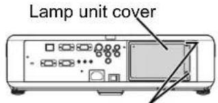
Lamp unit cover fixing screws
- Use a Phillips-head screwdriver to loosen the 2 lamp unit fixing screws.
- Hold the handles of the lamp unit and release the lamp unit lock.
- Pull the used lamp unit gently from the projector.
Lamp unit fixing screws
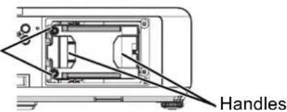
- Replace the new lamp unit in correct direction.
- RUNTIME of STATUS in the PROJECTOR SETUP menu will be reset to "0" automatically.
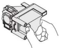
natural_image
Line drawing of a hand holding a mechanical device (no text or symbols)- Press in the lamp unit until it clicks and make sure the unit is installed securely.
- Tighten the 2 lamp unit fixing screws securely with a Phillips-head screwdriver.
Lamp unit
fixing screws
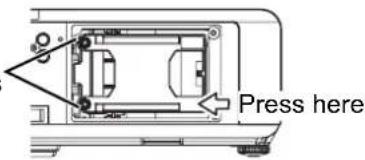
- Attach the lamp unit cover and tighten the 2 lamp unit cover fixing screws securely with a Phillipshead screwdriver.
Replacing the Auto Cleaning Filter (ACF)
■ Before replacing the ACF
● Wait until the cooling fan stops and the power indicator turn to red.
- Disconnect the power cord from the wall outlet.
● Prepare a Phillips-head screwdriver.
- Contact an Authorized Service Center to purchase a replacement ACF (ET-ACF100).
- When to replace the ACF
ACF is consumable product and effects on ventilation. The FILTER indicator will inform you of the replacement timing. You can check the remaining amount of the ACF in REMAINING FILTER of STATUS in PROJECTOR SETUP menu.
NOTE:
• See "WARNING MESSAGE" on page 38.
• See "REMAINING FILTER" on page 41.
• See "FILTER indicator" on page 47.
• The ACF operational sound may be heard.
- While the ACF is operating, the FILTER indicator will flash in green.
- When the FILTER indicator illuminate in orange, the remaining time of the ACF is less than 200 hours. This is rough estimated time and it depends on environment of usage. Contact an Authorized Service Center to purchase a replacement ACF.
- If you use the projector at 1 400 m (4 593 ft) above sea level, it may cause malfunction of the ACF.
- If you keep using the projector after the FILTER indicator illuminating in red, the indicator will start to flash in red for 10 minutes and the projector will be switched off.
- Replacement procedure
- Turn the projector upside down and place it gently on a soft cloth.
- Use a Phillips-head screwdriver to loosen 3 ACF cover fixing screws until the screws turn freely and remove the ACF cover.
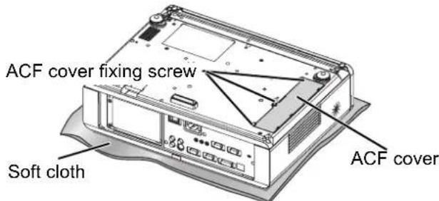
- Release the lock by pushing in the lock clamp to inside, and slide out the ACF unit from the projector slowly.
- Insert the new ACF unit into the compartment in correct direction and slightly push down until it clicks. Tighten an ACF fixing screw securely with a Phillips-head screwdriver.
- Attach the ACF cover and tighten the ACF cover fixing screws securely with a Phillips-head screwdriver.
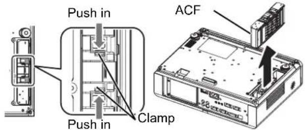
NOTE:
- If the ACF and/or ACF cover are attached incorrectly, the projector may not be turned on.
- Do not switch the power on while the ACF cover removed.
- When you replace the ACF unit, clean the compartment and/or the air exhaust port if you need to.
- The replacement timing of the ACF is 36 000 hours of use at maximum and it depends on environment of usage.
- Resetting the REMAINING FILTER
- Turn on the projector and display the FILTER COUNTER RESET in PROJECTOR SETUP.
- Press the ENTER button for more than 3 seconds. ● ● The confirmation screen will be displayed.
- Select OK by pressing ◀, then press the ENTER button.
- Display the STATUS and confirm the figure.
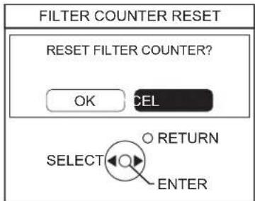
Troubleshooting
Should any problem persist, contact your dealer.
| Problem Cause | Reference page | |
| Power does not turn on. | ● The power cord may not be connected.● The MAIN POWER switch is turned off.● No electric supply is at the wall outlet.● TEMP indicator is lit or flashes.● LAMP indicator is lit or flashes.● The lamp unit cover has not been securely installed.● The circuit breakers have tripped. | 212321474749- |
| No picture appears. | ● The video signal input source may not be connected to a terminal properly.● The input selection setting may not be correct.● The BRIGHTNESS adjustment setting may be at the minimum setting.● The AV MUTE function may be in use. | 20263327 |
| The picture is fuzzy. | ● The lens focus may not have been set correctly.● The projector may not be at the correct distance from the screen.● The lens may be dirty.● The projector may be tilted too much. | 2415917 |
| The color is pale or grayish. | ● COLOR or TINT adjustment may be incorrect.● The input source which is connected to the projector may not be adjusted correctly. | 3330 |
| No sound can be heard from the internal speaker. | ● The audio signal source may not be connected properly.● A cable may be connected to the VARIABLE AUDIO OUT terminal.● The volume adjustment may be at the lowest possible setting. | 191329 |
| The control buttons of the projector do not operate. | ● CONTROL PANEL of CONTROL DEVICE SETUP in SECURITY menu is disabled. If you have a loss of the remote control while the CONTROL PANEL is disabled, press and hold the MENU button for 2 seconds with pressing the ENTER button. | 45 |
| The remote control does not operate. | ● REMOTE CONTROLLER of CONTROL DEVICE SETUP in SECURITY menu is disabled.● The batteries may be weak.● The batteries may not have been inserted correctly.● The remote control signal receptor on the projector may be obstructed.● The remote control unit may be out of the operation range. | 45-142525 |
| The picture does not display correctly. | ● The signal format (TV-SYSTEM) may not have been set correctly.● There may be a problem with the VCR or other signal source.● A signal which is not compatible with the projector is being input. | 34-52 |
| Picture from a computer does not appear. | ● The cable may be longer than the optional cable.● The external video output from a laptop computer may not be correct. (You may be able to change the external output settings by pressing the [Fn] + [F3] or [Fn] + [F10] keys simultaneously. The actual method varies depending on the type of computer; refer to the documentation provided with your computer for further details.)● COMPUTER2 SELECT setting in PROJECTOR SETUP menu is not correct. | -5441 |
| Picture from a computer DVI-D graphic board does not appear. | ● The graphic board driver of the computer needs to be updated to the latest version.● DVI-D IN setting in DISPLAY OPTION menu may be incorrect setting.● The computer may need to be restarted after switching DVI-D IN setting in DISPLAY OPTION menu of the projector correctly. | -38- |
Technical Information
List of compatible signals
| Mode | Display resolution (dots)*1 | Scanning frequency | Dot clock frequency | Picture quality*2 | PnP | Format*3 | |||
| H (kHz) | V (Hz) (MHz) RGB2 | DVI-DEIDI1 | DVI-DEIDI2 | ||||||
| NTSC/NTSC 4.43/PAL-M/PAL60 | 720 x 480i 15.7 | 59.9 - A | V/S | ||||||
| PAL/PAL-N/SECAM 720 x 576i 15.6 50.0 | A | ||||||||
| 525i (480i) 720 x 480i 15.7 59.9 13.5 | A | C/Y | |||||||
| 625i (576i) 720 x 576i 15.6 50.0 13.5 | A | ||||||||
| 525p (480p) | 720 x 483 | 31.5 | 59.9 | 27.0 | A | ● | D/C/Y | ||
| 625p (576p) | 720 x 576 | 31.3 | 50.0 | 27.0 | A | ● | |||
| 1 125 (1 080)/60i | 1 920 x 1 080i | 33.8 | 60.0 | 74.3 | A | ● | |||
| 1 125 (1 080)/50i | 1 920 x 1 080i | 28.1 | 50.0 | 74.3 | A | ● | |||
| 1 125 (1 080)/60p | 1 920 x 1 080 | 66.6 | 59.9 | 138.5 | A | ||||
| 1 125 (1 080)/50p | 1 920 x 1 080 | 55.6 | 49.9 | 141.5 | A | ||||
| 1 125 (1 080)/60p | 1 920 x 1 080p | 67.5 | 60.0 | 148.5 | A | ● | |||
| 1 125 (1 080)/50p | 1 920 x 1 080p | 56.3 | 50.0 | 148.5 | A | ● | |||
| 750 (720)/60p | 1 280 x 720 | 45.0 | 60.0 | 74.3 | AA | ● | |||
| 750 (720)/50p | 1 280 x 720 | 37.5 | 50.0 | 74.3 | AA | ● | |||
| VESA | 640 x 400 | 31.5 70.1 25.2 A | C | ||||||
| 640 x 400 | 37.9 85.1 31.5 A | ||||||||
| VGA | 640 x 480 | 31.5 | 59.9 | 25.2 | A | ● | ● | D/C | |
| 640 x 480 | 35.0 66.7 30.2 A | ● | C | ||||||
| 640 x 480 | 37.9 72.8 31.5 A | ● | |||||||
| 640 x 480 | 37.5 75.0 31.5 A | ● | |||||||
| 640 x 480 | 43.3 85.0 36.0 A | ||||||||
| SVGA | 800 x 600 | 35.2 56.3 36.0 A | ● | ||||||
| 800 x 600 | 37.9 | 60.3 | 40.0 | A | ● | ● | D/C | ||
| 800 x 600 | 48.1 72.2 50.0 A | ● | C | ||||||
| 800 x 600 | 46.9 75.0 49.5 A | ● | |||||||
| 800 x 600 | 53.7 85.1 56.3 A | ||||||||
| MAC | 832 x 624 | 49.7 | 74.6 | 57.3 | A | ● | |||
| XGA | 1 024 x 768 | 39.6 50.1 51.9 A | D/C | ||||||
| 1 024 x 768 | 48.4 | 60.0 | 65.0 | A | ● | ● | |||
| 1 024 x 768 | 56.5 | 70.1 | 75.0 | A | ● | ● | |||
| 1 024 x 768 | 60.0 | 75.0 | 78.8 | A | ● | ● | |||
| 1 024 x 768 | 68.7 85.0 94.5 A | ||||||||
| MXGA | 1 152 x 864 | 64.0 71.2 94.2 A | ● | C | |||||
| 1 152 x 864 | 67.5 74.9 | 108.0 A | |||||||
| 1 152 x 864 | 76.7 85.0 | 121.5 A | |||||||
| MAC | 1 152 x 870 | 68.7 | 75.1 | 100.0 | A | ● | |||
| MSXGA | 1 280 x 960 | 60.0 | 60.0 | 108.0 | A | ● | |||
| SXGA | 1 280 x 1 024 | 64.0 | 60.0 | 108.0 | A | ● | D/C | ||
| 1 280 x 1 024 | 80.0 | 75.0 | 135.0 | A | ● | C | |||
| 1 280 x 1 024 | 91.1 | 85.0 | 157.5 | B | |||||
| SXGA60+ | 1 400 x 1 050 | 64.0 60.0 | 108.0 A | ||||||
| 1 400 x 1 050 | 65.1 | 59.9 | 122.4 | A | ● | ● | D/C | ||
| UXGA | 1 600 x 1 200 | 75.0 | 60.0 | 162.0 | B | ● | C | ||
| WIDE750 (720) | 1 280 x 720 | 44.8 | 59.9 | 74.5 | AA | ● | |||
| 1 280 x 720 | 37.1 49.8 60.5 | AA | |||||||
| WXGA768*4 | 1 280 x 768 | 39.6 49.9 65.3 | AA | D/C | |||||
| 1 280 x 768 | 47.8 | 59.9 | 79.5 | AA | ● | ● | |||
| WXGA800*4 | 1 280 x 800 | 41.3 50.0 68.0 | AA | ||||||
| 1 280 x 800 | 49.1 60.2 69.1 | AA | C | ||||||
| 1 280 x 800 | 49.7 | 59.8 | 83.5 | AA | ● | ● | D/C | ||
| WXGA+ | 1 440 x 900 | 55.9 | 59.9 | 106.5 | A | ● | C | ||
| WSXGA+ | 1 680 x 1 050 | 65.3 | 60.0 | 146.3 | A | ● | |||
| WUXGA | 1 920 x 1 200 | 74.6 | 59.9 | 154.0 | B | ||||
*1. The "i" appearing after the resolution indicates an interlaced signal.
*2. The following symbols are used to indicate picture quality.
AA Maximum picture quality can be obtained.
A Signals are converted by the image processing circuit before picture is projected.
B Some loss of data occurs to make projection easier.
*3. The following symbols are used to indicate the format.
V = VIDEO, S = S-VIDEO, D = DVI, C = COMPUTER, Y = YPBPR
*4. The best signal for 16:10 is WXGA800, 16:9 is WXGA768.
Serial terminal
The serial connector which is on the connector panel of the projector conforms to the RS-232C interface specification, so that the projector can be controlled by a personal computer which is connected to this connector.
- Connection
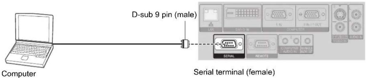
- Pin assignments and signal names
| Pin No. Signal name Contents | |||
| 1 | NC | ||
| 2 | TXD Transmitted data | ||
| 3 | RXD Received data | ||
| 4 | NC | ||
| 5 | GND Earth | ||
| 6 | NC | ||
| 7 | RTS | Connected internally | |
| 8 | CTS | ||
| 9 | NC | ||
- Communication settings
| Signal level | RS-232C | Character length | 8 bits |
| Sync. method | Asynchronous | Stop bit | 1 bit |
| Baud rate | 9 600 bps | X parameter | None |
| Parity | None | S parameter | None |
Basic format
| STX | Command | : | Parameter | ETX |
| Start byte(02h) | 3 bytes | 1 byte | 1 byte -4 bytes | End(03h) |
- The projector can not receive any command for 10 seconds after the lamp is switched on. Wait 10 seconds before sending the command.
- If sending multiple commands, check that a response has been received from the projector for one command before sending the next command.
- When a command which does not require parameters to be sent, the colon (:) is not required.
- If an incorrect command is sent from the personal computer, the ER401 command will be sent from the projector to the personal computer.
- Cable specifications
(When connected to a personal computer)
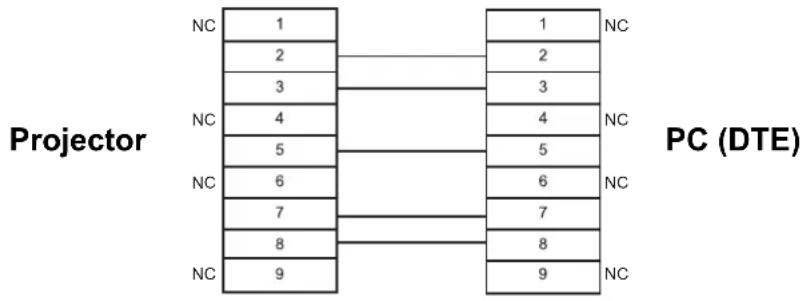
flowchart
graph TD
    A["Projector"] --> B["PC (DTE)"]
    B --> C["1"]
    B --> D["2"]
    B --> E["3"]
    B --> F["4"]
    B --> G["5"]
    B --> H["6"]
    B --> I["7"]
    B --> J["8"]
    B --> K["9"]
    style A fill:#f9f,stroke:#333
    style B fill:#ccf,stroke:#333
- Control commands
| Command Control contents Remarks | ||
| PON Power ON | In standby mode, all commands other than the PON command are ignored.● ● The PON command is ignored during lamp ON control. | |
| POF Power OFF | If a PON command is received while the cooling fan is operating after the lamp has switched off, the lamp is not turned back on again straight away in order to protect the lamp. | |
| AVL Volume | Parameter000 - 063 (Adjustment value 0 - 63) | |
| IIS INPUT | Parameter:VID = VIDEORG1 = COMPUTER1DVI = DVI SVD = S-VIDERG2 = COMPUTER2NWP = NETWORK | |
| Q$S Lamp condition query | Call back0 = Standby 2 = Lamp ON1 = Lamp ON control active 3 = Lamp OFF control active | |
| OSH AV MUTE | Turning off the projection and sound temporarily.Send the command to switch between ON and OFF.Do not send the command consecutively. | |
Computer connection guidance
You can switch the signals which to output from the COMPUTER1 OUT terminal by pressing the computer key command. The key commands are depend on the manufactures. If you select the computer terminals which has no signals while the INPUT GUIDE is set to DETAILED, the computer connection guidance will be displayed.
| Manufacturer | Key command | Manufacturer | Key command | Manufacturer | Key command |
| Panasonic NEC |  | TOSHIBA SHARP HP |  | IBM SONY | Fn + F7 |
| Apple | F7 | ||||
| FUJITSU |  | EPSON DELL |  | Others | Fn + □/□ |
NOTE:
- The computer connection guidance will disappear after 5 minutes.
- Please refer the instructions which provided with the computers for more detailed information.
REMOTE terminal
You can remotely operate the projector from the outside the remote control range by connecting to the REMOTE terminal.
Pin assignments and signal names
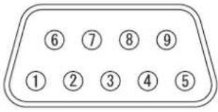 | Pin No. Signal name Contents | ||
| 1 | GND Ground | ||
| 2 | POWER POWER ON | ||
| 3 | INPUT SEL3 Select input signal 3 | ||
| 4 | NC | ||
| 5 | INPUT SEL1 Select input signal 1 | ||
| 6 | INPUT SEL2 Select input signal 2 | ||
| 7 | Connect internally | ||
| 8 | |||
| 9 | ENABLE Control by external contact | ||
LAMP switching
| Pin No. Settings | ||
| 2 - 1 | Short Open | |
| Operation On Off | ||
Switching input signals
| Pin No. Settings | ||||||
| 3 - 1 | Open Open | Open Short Short | Open | |||
| 5 - 1 | Open Short | Open Open Short | Short | |||
| 6 - 1 | Open Open | Short Open Open | Short | |||
| Input signal | COMPUTER1 | COMPUTER2 | DVI | VIDEO | S-VIDEO | NETWORK |
NOTE:
- When pin ① and pin ⑨ are short-circulated, the buttons on the projector's control panel, power and INPUT SELECT buttons on the remote control cannot be used. In addition, the RS-232C commands and network functions that correspond to these functions cannot be used either.
- While pin ⑨ is "Open", do not short-circuit pin ①, ②, ③, ⑤ and ⑥. The projector would reject all the signals from the remote control.
NOTE:
DVI-D IN terminal
● Pin assignments and signal names
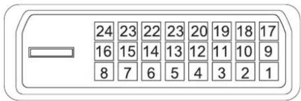
| Pin No. | Signal name | Pin No. | Signal name |
| 1 | T M D | S D | a t a |
| 2 | T M D | S D | a t a |
| 3 | TMDS Data 2/4 shield | 15 GND | |
| 4 16 Hot Plug Detect | |||
| 5 17 TMDS Data 0- | |||
| 6 DDC clock 18 TMDS Data 0+ | |||
| 7 DDC data 19 | TMDS Data 0/5 shield | ||
| 8 | 20 | ||
| 9 | T M D | S D | a t a |
| 10 TMDS Data 1+ | 22 TMDS clock shield | ||
| 11 | TMDS Data 1/3 shield | 23 TMDS clock+ | |
| 12 | 24 TMDS clock- | ||
2 2
1
Ceiling mount bracket safeguards
The projector and the ceiling mount bracket are designed sufficiently safety though, make sure the safety cable provided with the projector is installed and attached to the bottom of the projector when mounting on the ceiling for safety and security.
NOTE:
- Even if it is guarantee period, the manufacturer is not responsible for any hazard or damage caused by using a ceiling mount bracket which is not purchased from an authorized distributors, or environmental conditions.
- Make sure to use a torque driver and do not use an electrical screwdriver or an impact screwdriver.
- Installation work of the ceiling mount bracket should only be carried by a qualified technician.
- Remove an unused ceiling mount bracket promptly.
● Installing the safety cable
- Install the ceiling mount bracket according to the installation instructions.
- Loop the security cable around the ceiling mount bracket with less slack.
● Lace the cable of the end with a latch through the loop on the other end of the cable.
- Attach the latch on to the bottom of the projector with a provided screw.
● ● Torque: 1.25±0.2 N·m
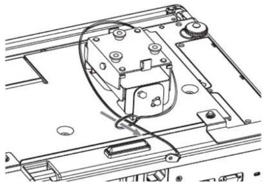
natural_image
Technical line drawing of a mechanical assembly with no visible text or symbols* Indicated sample above is ET-PKF100S.
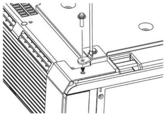
natural_image
Technical line drawing of a mechanical assembly with no visible text or symbolsScreen size and throw distance for 16:9 aspect ratio
All measurements and the calculation results below are approximate and may differ slightly from the actual measurements.
| Projection size (16 : 9) Throw distance (L) | ||||
| Screen diagonal (SD) Screen height (SH) Screen width (SW) | Minimum distance (LW) | Maximum distance (LT) | ||
| 33" (0.84 m) | 0.41 m (1'4") | 0.73 m (2'4") | 1.9 m (6'2") | |
| 40" (1.02 m) | 0.50 m (1'7") | 0.89 m (2'11") | 1.2 m (3'11") | 2.3 m (7'6") |
| 50" (1.27 m) | 0.62 m (2') | 1.11 m (3'7") | 1.5 m (4'11") | 2.9 m (9'6") |
| 60" (1.52 m) | 0.75 m (2'5") | 1.33 m (4'4") | 1.7 m (5'6") | 3.5 m (11'5") |
| 70" (1.78 m) | 0.87 m (2'10") | 1.55 m (5'1") | 2.0 m (6'6") | 4.1 m (13'5") |
| 80" (2.03 m) | 1.00 m (3'3") | 1.77 m (5'9") | 2.3 m (7'6") | 4.7 m (15'5") |
| 90" (2.29 m) | 1.12 m (3'8") | 1.99 m (6'6") | 2.6 m (8'6") | 5.3 m (17'4") |
| 100" (2.54 m) | 1.25 m (4'1") | 2.21 m (7'3") | 2.9 m (9'6") | 5.9 m (19'4") |
| 120" (3.05 m) | 1.49 m (4'10") | 2.66 m (8'8") | 3.5 m (11'5") | 7.1 m (23'3") |
| 150" (3.81 m) | 1.87 m (6'1") | 3.32 m (10'10") | 4.4 m (14'5") | 8.8 m (28'10") |
| 200" (5.08 m) | 2.49 m (8'2") | 4.43 m (14'6") | 5.9 m (19'4") | 11.8 m (38'8") |
| 250" (6.35 m) | 3.11 m (10'2") | 5.53 m (18'1") | 7.4 m (24'3") | 14.7 m (48'2") |
| 300" (7.62 m) | 3.74 m (12'3") | 6.64 m (21'9") | 8.9 m (29'2") | 17.7 m (58') |
Calculation methods
$$ \mathrm{SW} (\mathrm{m}) = \mathrm{SD} \left(^ {\prime \prime}\right) \times 0. 0 2 2 1 \mathrm{SH} (\mathrm{m}) = \mathrm{SD} \left(^ {\prime \prime}\right) \times 0. 0 1 2 5 $$
$$ \mathrm{LW} (\mathrm{m}) = 0. 0 2 9 7 \times \mathrm{SD} (^ {\prime \prime}) - 0. 0 4 5 \mathrm{LT} (\mathrm{m}) = 0. 0 5 9 2 \times \mathrm{SD} (^ {\prime \prime}) - 0. 0 6 1 $$
Screen size and throw distance for 4:3 aspect ratio
All measurements and the calculation results bellow are approximate and may differ slightly from the actual measurements.
| Projection size (4 : 3) | Throw distance (L) | ||||
| Screen diagonal (SD) | Screen height (SH) | Screen width (SW) | Minimum distance (LW) | Maximum distance (LT) | |
| 33" (0.84 m) | 0.50 m (1'7") | 0.67 m (2'2") | 2.1 m (6'10") | ||
| 40" (1.02 m) | 0.61 m (2') | 0.81 m (2'7") | 1.3 m (4'3") | 2.6 m (8'6") | |
| 50" (1.27 m) | 0.76 m (2'5") | 1.02 m (3'4") | 1.6 m (5'2") | 3.2 m (10'5") | |
| 60" (1.52 m) | 0.91 m (2'11") | 1.22 m (4') | 1.9 m (6'2") | 3.9 m (12'9") | |
| 70" (1.78 m) | 1.07 m (3'06") | 1.42 m (4'7") | 2.3 m (7'6") | 4.5 m (14'9") | |
| 80" (2.03 m) | 1.22 m (4') | 1.63 m (5'4") | 2.6 m (8'6") | 5.2 m (17') | |
| 90" (2.29 m) | 1.37 m (4'5") | 1.83 m (6') | 2.9 m (9'6") | 5.8 m (19') | |
| 100" (2.54 m) | 1.52 m (4'11") | 2.03 m (6'7") | 3.2 m (10'5") | 6.5 m (21'3") | |
| 120" (3.05 m) | 1.83 m (6') | 2.44 m (8') | 3.9 m (12'9") | 7.8 m (25'7") | |
| 150" (3.81 m) | 2.29 m (7'6") | 3.05 m (10') | 4.9 m (16') | 9.8 m (32'1") | |
| 200" (5.08 m) | 3.05 m (10') | 4.06 m (13'3") | 6.5 m (21'3") | 13.0 m (42'7") | |
| 250" (6.35 m) | 3.81 m (12'6") | 5.08 m (16'8") | 8.2 m (26'10") | 16.3 m (53'5") | |
| 300" (7.62 m) | 4.57 m (14'11") | 6.10 m (20') | 9.8 m (32'1") | 19.5 m (63'11") | |
Calculation methods
$$ \mathrm{SW} (\mathrm{m}) = \mathrm{SD} \left(^ {\prime \prime}\right) \times 0. 0 2 0 3 \mathrm{SH} (\mathrm{m}) = \mathrm{SD} \left(^ {\prime \prime}\right) \times 0. 0 1 5 2 $$
$$ \mathrm{LW} (\mathrm{m}) = 0. 0 3 3 9 \times \mathrm{SD} (^ {\prime \prime}) - 0. 0 5 2 \mathrm{LT} (\mathrm{m}) = 0. 0 6 5 3 \times \mathrm{SD} (^ {\prime \prime}) - 0. 0 5 2 $$
Specifications
| Power supply | AC 100 - 240 V 50 Hz/60 Hz | |
| Power consumption | 350 WDuring standby (when fan is stopped): Approx. 4 W*1 | |
| Amps | 4.1 A - 1.5 A | |
| LCD panel | Panel size (diagonal) | 0.74 type |
| Aspect ratio | 16 : 10 | |
| Display method | 3 transparent LCD panels (RGB) | |
| Drive method | Active matrix method | |
| Pixels | 1 024 000 (1 280 x 800) x 3 panels | |
| Lens | Manual zoom (2x)/Manual focusF 1.7 - 2.6, f 21.6 mm - 43.0 mm | |
| Lamp | UHM lamp (250 W) | |
| Luminosity*2 | 3 300 lm | |
| Operating environment | 0 °C - 40 °C (32 °F - 104 °F)TemperatureWhen the HIGH ALTITUDE MODE(page 42) is set to ON: 0 °C - 35 °C(32 °F - 95 °F)Humidity 20% - 80% (no condensation) | |
| Scanning frequency*3(for RGB signal) | Horizontal scanning frequency | 15 kHz - 91 kHz |
| Vertical scanning frequency | 50 Hz - 85 Hz | |
| Dot clock frequency | Less than 150 MHz | |
| COMPONENT (YPBPR) signals | 525i (480i), 525p (480p), 625i (576i), 625p (576p), 750 (720)/60p,750 (720)/50p, 1 125 (1 080)/60i, 1 125 (1 080)/50i, 1 125 (1 080)/60p,1 125 (1 080)/50p | |
| Color system | 7 (NTSC/NTSC 4.43/PAL/PAL-M/PAL-N/PAL60/SECAM) | |
| Projection size | 33" - 300" (838.2 mm - 7 620 mm) | |
| Throw distance | 1.1 m - 19.5 m (3'7" - 64'0") | |
| Screen aspect ratio | 16 : 10 | |
| Installation | FRONT/DESK, FRONT/CEILING, REAR/DESK, REAR/CEILING (Menu selection method) | |
| Speaker | 1 piece (Monaural) 4 cm (Round) | |
| Max. useable volume output | 5.0 W | |
*1. When NETWORK STANDBY in NETWORK menu is ON: Approx. 25 W
When IN STANDBY MODE of AUDIO SETTING in PROJECTOR SETUP menu is ON: Approx. 35 W
The maximum power consumption during standby: Approx. 35 W.
*2. Measurement, measuring conditions and method of notation all comply with ISO21118 international standards.
*3. See "List of compatible signals" on page 52 for available signals.
| Terminals | S-VIDEO IN | Single - line, Mini DIN 4pY: 1.0 V [p-p], C: 0.286 V [p-p], 75 Ω | |
| VIDEO IN | Single - line, RCA pin jack1.0 V [p-p], 75Ω | ||
| COMPUTER1 IN | Single - line, D - sub HD 15-pin (female)R.G.B. 0.7 V [p-p], 75 ΩHD, VD/SYNC TTL high impedance, automatic positive/negative polarity compatible | ||
| COMPUTER2 IN/1 OUT | Single - line, D - sub HD 15-pin (female)Selectable for input and output by menu operation.R.G.B. 0.7 V [p-p], 75 ΩHD, VD/SYNC TTL high impedance, automatic positive/negative polarity compatible | ||
| DVI-D IN | Single - line, DVI-D 24-pin DVI 1.0 compatible(Single link) HDCP compatible | ||
| AUDIO IN | Single - line, 0.5V [rms], RCA pin jack x 2 (L - R) | ||
| COMPUTER AUDIO IN | Dual - line, 0.5V [rms], M3 jack (Stereo MINI) | ||
| VARIABLE AUDIO OUT | Single - line, 0.5V [rms], M3 jack (Stereo MINI)Monitor output/stereo compatible0 V [rms] - 2.0 V [rms] (variable) | ||
| SERIAL | D-sub 9-pin RS-232C compatible | ||
| REMOTE | D-sub 9-pin For external control | ||
| LAN (RJ-45) | Single - line, For network connection10 Base-T/100Base-TX | ||
| Wireless LAN(PT-FW300NTU only) | Compatible | IEEE802.11b/IEEE802.11g (Wireless LAN standard protocol) | |
| Wireless channel | IEEE802.11b/IEEE802.11g: 1 - 13 channels | ||
| Distance | 30 m (98'5") Depends on the usage environment | ||
| Cabinet | Moulded plastic (PC+ABS) | ||
| Dimensions | Width 432 mm (17")Height 128.5 mm (5 - 1/32")Length 323 mm (12 - 11/16") | ||
| Weight | Approx. 6.2 kg (13.7 lbs.)*1 | ||
| Certifications | UL60950-1 C-ULFCC Class B ICES-003 | ||
| Remote control | Power supply | 3 V DC (AA battery x 2) | |
| Operating range | Approx. 15 m (49'2") (when operated directly in front of signal receptor) | ||
| Weight | 117 g (4.2 ozs.) (including batteries) | ||
| Dimensions | Width 48 mm (1 - 7/8")Length 163 mm (6 - 13/32")Height 24.5 mm (-15/16") (not including surface projection parts) | ||
| Options Ceiling bracket | ET-PKF100H/ET-PKF100S | ||
*1. Average value. Each product has an individual variable in weight.
Dimensions
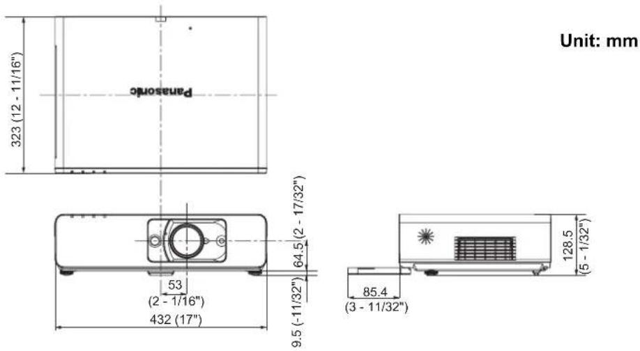
Trademark acknowledgements
● VGA and XGA are trademarks of International Business Machines Corporation.
● S-VGA is a registered trademark of the Video Electronics Standards Association.
- HDMI, the HDMI logo and High-Definition Multimedia Interface are trademarks or registered trademarks of HDMI Licensing LLC.
- The font used in the on-screen displays is a Ricoh bitmap font, which is manufactured and sold by Ricoh Company, Ltd.
All other trademarks are the property of the various trademark owners.
Index
A
AC IN 13
Accessories 10
Air exhaust port 13
Air intake port 12
Ambient Luminance Sensor (ALS) 12
ASPECT 36
AUDIO IN 13
AUDIO SETTING 42
Auto Cleaning Filter (ACF)
Compartment 13
FILTER indicator 12
FILTER indicator status 47
Replacing 49
AUTO SETUP
Menu 39
Remote control button 14
Remote control function 25
AV MUTE 40
Remote control button 14
Remote control function 27
B
BACK COLOR 39
BALANCE 42
Battery compartment 14
BRIGHTNESS 33
C
Calculation methods
16:10 15
16:9 57
4:3 57
CD-ROM 10
CINEMA 33
Cleaning 48
CLOCK PHASE 35
CLOSED CAPTION SETTING 38
COLOR 33
COLOR TEMPERATURE 34
COMPUTER
Connection guidance ....54
Remote control button 14
Remote control function 26
COMPUTER AUDIO IN 13
COMPUTER1 IN 13
COMPUTER2 IN/1 OUT 13
COMPUTER2 SELECT 41
Connections 19
CONTRAST 33
CONTROL DEVICE SETUP 45
D
DAYLIGHT VIEW 34
DEFAULT
Remote control button 14
Remote control function 27
DIGITAL CINEMA REALITY 34
DIGITAL ZOOM
Remote control button 14
Remote control function 26
Dimensions 60
Direct power off 21
Direct power on 21
DISPLAY OPTION menu 38
DOT CLOCK 35
DOUBLE-WINDOW 28
DVI EDID 38
DVI SIGNAL LEVEL 38
DVI-D IN 13, 38
Pin assignments 56
E
EMULATE 42
ENTER
Control panel button 12
Remote control button 14
F
FILTER COUNTER RESET 43
Focus lever 12, 24
FRAME LOCK 37
FREEZE
Remote control button 14
Remote control function 27
Front leg adjusters 13, 16, 24
Front panel cover 12
FUNCTION
Remote control button 14
Remote control function 28
FUNCTION BUTTON 42
H
Hand strap 14
HIGH ALTITUDE MODE 42
|
INDEX-WINDOW
Remote control button 14
Remote control function 27
INITIAL STARTUP 41
INITIALIZE ALL 43
INPUT SELECT
Control panel button 12
Function 24, 26
INSTALLATION
Menu 42
Projection method 16
K
KEYSTONE 35
L
LAMP
Indicator 12
Indicator status 47
Lamp unit compartment 13
Replacing 48
LAN 13
LASER
Remote control button 14
Remote control function 29
Lens shift lever 12, 17, 24
Lever
Focus lever 12
Lens shift lever 12
Zoom lever 12
M
MENU Control panel button 12
Navigation 32
Remote control button 14
Structure 30
MENU LOCK 45
MENU LOCK PASSWORD 45
N
Navigation buttons Control panel button .... 12 Navigating .... 32 Remote control button .... 14
NETWORK Remote control button .... 14 Remote control function .... 26 NO SIGNAL SHUT-OFF .... 41 NOISE REDUCTION .... 34
0
ON-SCREEN DISPLAY 38 OTHER FUNCTIONS 40
P
PASSWORD ....44 PASSWORD CHANGE ....44 PICTURE menu ....33 PICTURE MODE ....33 POSITION menu ....35 Power Control panel button ....12 Indicator ....12 Indicator status ....22 Remote control button ....14
Power cord Accessories .... 10 Connecting .... 21
Power cord secure lock Accessories .... 10 Attaching .... 21 Projection lens .... 12 PROJECTOR SETUP menu .... 41
R
REMAINING FILTER .... 41 REMOTE .... 13 LAMP switching .... 55 Pin assignments .... 55 Switching input signals .... 55 Remote control Accessories .... 10 Indicator .... 14 Signal emitter .... 14 Signal receptor .... 12 RETURN Control panel button .... 12 Remote control button .... 14 RGB/YPBPR .... 34 RUNTIME .... 41
S
Safety cable Accessories .... 10 Safeguards .... 56 SCREEN FORMAT .... 38 SCREEN POSITION .... 39 SCREEN SETTING .... 38 Screen size 16:10 .... 15 16:9 .... 57 4:3 .... 57 Security lock .... 13 SECURITY menu .... 44
SERIAL 13
Basic format 53
Cable specifications 54
Communication settings 53
Connection 53
Control commands 54
Pin assignments 53
SHARPNESS 33
SHIFT 35
SHIFT V 35
SIDE BY SIDE
Remote control button 14
Remote control function 28
SIGNAL 41
SIGNAL SEARCH 39
Speaker 12
Specifications 58
STARTUP LOGO 39
STATUS 41
S-VIDEO IN 13
SXGA MODE 39
T
TEMP Indicator .... 12 Indicator status .... 47 TEST PATTERN .... 43 TEXT CHANGE .... 44 TEXT DISPLAY .... 44 Throw distance 16:10 .... 15 16:9 .... 57 4:3 .... 57 Throwing angle .... 16 TINT .... 33 Troubleshooting .... 51 TV-SYSTEM .... 34
V
VARIABLE AUDIO OUT ....13 VIDEO Remote control button ....14 Remote control function ....26 VIDEO IN ....13 VOLUME Controlling ....42 Remote control button ....14 Remote control function ....29
W
WHITE BALANCE BLUE ....33 WHITE BALANCE GREEN ....33 WHITE BALANCE RED ....33 WIDE MODE ....39
Z
Zoom lever 12, 24
Cher client Panasonic:
natural_image
Line drawing of a plug with two leads and a pointed tip, no text or symbols presentNe pas retirer
Pursuant to at the directive 2004/108/EC, article 9(2)
Panasonic Testing Centre
Panasonic Service Europe, a division of Panasonic Marketing Europe GmbH
Winsbergring 15, 22525 Hamburg, F.R. Germany
NOTICE:
Fabricant responsible: Panasonic Corporation of North America
Adresse: One Panasonic Way, Secaucus, New Jersey 07094
Téléphone: (888) 411 - 1996
Email: projectorsupport@us.panasonic.com
natural_image
Front view of a computer monitor with control panel and buttons (no visible text or labels)natural_image
Illustration of a hand holding a mechanical device (no text or symbols visible)natural_image
Technical line drawing of a mechanical assembly with no visible text or symbolsnatural_image
Technical line drawing of a mechanical assembly with no visible text or symbolsNOTE:
This product contains a CR Coin Cell Lithium Battery which contains Perchlorate Material - special handling may apply.
See www.dtsc.ca.gov/hazardouswaste/perchlorate.
Panasonic Corporation
Web Site : http://panasonic.net/avc/projector/
© Panasonic Corporation 2009
Panasonic Projector Systems Company
Unit of Panasonic Corporation of North America
One Panasonic Way, Secaucpus, NJ 07094
TEL: (201) 392 - 6591
Technical Support:
TEL: (888) 411 - 1996
FAX: (201) 348 - 7523
E-Mail: projectorsupport@us.panasonic.com
Panasonic Canada Inc.
5770 Ambler Drive, Mississauga, Ontario L4W 2T3
TEL: (905) 624 - 5010
Panasonic Puerto Rico, Inc.
Ave. 65 de Infanteria, Km 9.5 San Gabriel Industrial Park, Carolina, Puerto Rico 00985
TEL: (787) 750 - 4300
Printed in Japan
S0908-3019D
- Model No. PT-FW300NTU PT-FW300U
- Important Safety Notice
- Dear Panasonic Customer:
- WARNING
- NOTICE:
- WARNING:
- Declaration of Conformity
- Information on Disposal in other Countries outside the European
- Contents
- Quick steps
- Important Information
- Preparation
- Getting Started
- Basic Operation
- Settings Maintenance
- Menu Navigation ....30
- PICTURE menu....33
- POSITION menu 35
- DISPLAY OPTION menu ....38
- PROJECTOR SETUP menu ....41
- SECURITY menu 44
- NETWORK menu 46
- TEMP, LAMP and FILTER Indicators 47
- Care and Replacement.... 48
- Troubleshooting 51
- Appendix
- Technical Information 52
- Index....61
- Precautions with regard to safety
- WARNINGS
- Do not touch the leaked liquid from the batteries.
- During a thunderstorm, do not touch the projector or the cable.
- Do not use the projector in a bath or shower.
- Do not place your skin into the light beam while the projector is being used.
- Do not look into the lens while the projector is being used.
- Do not place your hands or other objects close to the air outlet port.
- Replacement of the lamp is recommended to be carried out by a qualified technician.
- When replacing the lamp, allow it to cool for at least one hour before handling it.
- Before replacing the lamp, be sure to disconnect the power plug from the wall outlet.
- Do not allow infants or pets to touch the remote control unit.
- CAUTIONS
- Do not cover the air inlet port or the air outlet port.
- Do not set up the projector in humid or dusty places or in places where the projector may come into contact with oily smoke or steam.
- Do not set up the projector in a high temperature environment, such as near a heater or in direct sunlight.
- Do not set up the projector outdoors.
- When disconnecting the power cord, hold the plug, not the cord.
- Always disconnect all cables before moving the projector.
- Do not place any heavy objects on top of the projector.
- Do not short-circuit, heat or disassemble the batteries or place them into water or fire.
- When inserting the batteries, make sure the polarities (+ and -) are correct.
- Use only the specified batteries.
- Do not mix old and new batteries.
- Remove the used batteries from the remote control promptly.
- If not using the projector for an extended period of time, disconnect the power plug from the wall outlet and remove the batteries from the remote control.
- Do not put your weight on this projector.
- Disconnect the power plug from the wall outlet as a safety precaution before carrying out any cleaning.
- If the lamp has broken, ventilate the room immediately. Do not touch or bring your face close to the broken pieces.
- Ask an Authorized Service Center to clean inside the projector at least once a year.
- Do not use chemical treated wipes when cleaning.
- Cautions when transporting
- Do not subject the projector to excessive vibration or shocks.
- When transporting the projector, hold the body at the bottom securely.
- Cautions when installing
- Avoid setting up in places which are subject to vibration or shocks.
- Avoid setting up in places which are subject to sudden temperature changes, such as near an air conditioner or lighting equipment.
- Do not set up the projector near high-voltage power lines or near motors.
- If installing the projector to the ceiling, ask a qualified technician to carry out all installation work.
- If using this projector at high elevations 1 400 - 2 700 m (4 593 - 8 858 ft) sea level, set the HIGH ALTITUDE MODE to ON. See “HIGH ALTITUDE MODE” on page 42.
- Cautions on use
- In order to get the best picture quality
- Do not touch the surfaces of the lens or the front glass with your bare hands.
- Liquid crystal panel
- The projector has a high pressure mercury lamp and that is characterized as follows.
- Optical components
- Security
- Take the safety measures for use of the projector that should cover the following envisioned incidents.
- Security instruction
- Accessories
- Read this first
- Minimum required setting screen
- ● INITIAL SETTING
- INSTALLATION
- SCREEN FORMAT
- SCREEN POSITION
- HIGH ALTITUDE MODE
- NOTE:
- About Your Projector
- Projector body
- ● Top and front view
- Back and bottom view
- Remote control
- Attaching a hand strap
- Top view
- Remote control indicator
- Power button
- /I
- AUTO
- COMPUTER
- RETURN
- AV MUTE
- INDEX-WINDOW
- continues.
- SIDE BY SIDE
- Automatically adjust the
- setting of SHIFT, DOT
- CLOCK, CLOCK PHASE
- and SIGNAL SEARCH for
- cted image of COMPUTER/
- al. (page 25)
- Switch the required input
- Return to the previous menu.
- (page 32)
- Turn off the projection
- temporarily. (page 27)
- Display the frozen image
- while the display of
- subsequent images
- (page 27)
- : Display 2 different source
- Control to adjust the volume
- of the speaker. (page 29)
- MULTI-LIVE
- NETWORK
- ▲
- Battery compartment
- Setting up
- Screen size and throw distance
- Calculation methods
- Projection method
- Front leg adjusters and throwing angle
- Lens shift and positioning
- ■ Adjusting the lens shift lever
- ● Horizontal shift
- ● Vertical shift
- ■ Projector location range
- ● When the screen position is fixed
- ● When the projector position is fixed
- Connections
- Before connection to the projector
- Connecting example: Computers
- LAN terminal
- Connecting example: AV equipment
- Connecting with VIDEO IN/S-VIDEO IN
- Connecting with DVI-D IN
- Switching the projector on/off
- Power cord
- - Connecting
- - Disconnecting
- - Direct power on function
- ● Direct power off function
- Power indicator
- Switching on the projector
- Switching off the projector
- Projecting an image
- Selecting the input signal
- Positioning the image
- Remote control operation
- Operating range
- ● Facing to the projector
- ● Facing to the screen
- Setting up the image position automatically
- Switching the input signal
- - Pressing the COMPUTER button
- ● Pressing the NETWORK button
- - Pressing the VIDEO button
- - Pressing the INPUT SELECT button on the projector
- Enlarging the centered area
- ●● Enlarging the image
- ● Shifting the center point
- Capturing an image
- Stopping the projection
- Resetting to the factory default settings
- Projecting an image in INDEX-WINDOW mode
- ● Switching the position
- ● Changing the image size
- ● Capturing a new image
- Using an assigned function
- Projecting 2 different source image at a time
- ● Switching the signal
- Side by Side function signal combination table
- Using the laser pointer
- - Disable the LASER button
- Controlling the volume of the speaker
- Menu Navigation
- Main menu and Sub-menu
- PICTURE
- POSITION
- LANGUAGE
- DISPLAY OPTION
- Navigating through the menu
- ● Displaying the Main menu
- - Adjusting with the bar scale items
- ● Returning to the previous menu
- ● Operating procedure
- PICTURE menu
- PICTURE MODE
- CONTRAST
- BRIGHTNESS
- COLOR
- TINT
- SHARPNESS
- WHITE BALANCE RED
- WHITE BALANCE GREEN
- WHITE BALANCE BLUE
- COLOR TEMPERATURE
- DAYLIGHT VIEW
- DIGITAL CINEMA REALITY
- NOISE REDUCTION
- TV-SYSTEM
- RGB/YPBPR
- POSITION menu
- KEYSTONE
- SHIFT
- SHIFT V
- DOT CLOCK
- CLOCK PHASE
- OVER SCAN
- ASPECT
- ■ Aspect ratio options
- 4:3
- 16:9
- H-FIT
- V-FIT
- HV-FIT
- ● THROUGH
- FRAME LOCK
- DISPLAY OPTION menu
- ON-SCREEN DISPLAY
- - INPUT GUIDE
- - OSD DESIGN
- ● WARNING MESSAGE
- DVI-D IN
- • DVI EDID
- ● DVI SIGNAL LEVEL
- CLOSED CAPTION
- SETTING
- MODE
- SCREEN SETTING
- - SCREEN FORMAT
- ● SCREEN POSITION
- STARTUP LOGO
- ● Editing the original text
- AUTO SETUP
- SIGNAL SEARCH
- BACK COLOR
- WIDE MODE
- SXGA MODE
- OTHER FUNCTIONS
- PROJECTOR SETUP menu
- STATUS
- Items Description
- ● SIGNAL
- ● RUNTIME
- ● REMAINING FILTER
- COMPUTER2 SELECT
- NO SIGNAL SHUT-OFF
- INITIAL START UP
- EMULATE
- FUNCTION BUTTON
- AUDIO SETTING
- ● VOLUME
- ● BALANCE
- ● IN STANDBY MODE
- ● AUDIO IN SELECT
- ● DVI
- ● COMPUTER1
- ● COMPUTER2
- TEST PATTERN
- INITIALIZE ALL
- FILTER COUNTER RESET
- SECURITY menu
- ● Entering the SECURITY menu
- ● After you change the password
- PASSWORD
- PASSWORD CHANGE
- TEXT DISPLAY
- TEXT CHANGE
- MENU LOCK
- MENU LOCK PASSWORD
- CONTROL DEVICE SETUP
- ● CONTROL PANEL
- ● REMOTE CONTROLLER
- NETWORK menu
- Items in NETWORK menu
- TEMP, LAMP and FILTER Indicators
- Managing the indicated problems
- ● LAMP indicator
- - TEMP indicator
- - FILTER indicator
- Care and Replacement
- Cleaning the projector
- ■ Before cleaning the projector
- - Cleaning the outer surface of the projector
- - Cleaning the lens and front glass surface
- Replacing the Lamp unit
- ■ Before replacing the Lamp unit
- - When to replace the lamp unit
- - Replacement procedure
- ●-Removing and replacing the lamp unit
- Replacing the Auto Cleaning Filter (ACF)
- ■ Before replacing the ACF
- - When to replace the ACF
- - Resetting the REMAINING FILTER
- Troubleshooting
- Technical Information
- Serial terminal
- - Connection
- - Pin assignments and signal names
- - Communication settings
- Basic format
- - Cable specifications
- - Control commands
- Computer connection guidance
- REMOTE terminal
- DVI-D IN terminal
- ● Pin assignments and signal names
- Ceiling mount bracket safeguards
- ● Installing the safety cable
- Screen size and throw distance for 16:9 aspect ratio
- Screen size and throw distance for 4:3 aspect ratio
- Dimensions
- Trademark acknowledgements
- Index
- A
- B
- C
- D
- E
- F
- H
- |
- K
- L
- M
- N
- 0
- P
- R
- S
- T
- V
- W
- Z
- Cher client Panasonic:
- Panasonic Corporation
- Panasonic Projector Systems Company
- Technical Support:
- Panasonic Canada Inc.
- Panasonic Puerto Rico, Inc.
Brand : PANASONIC
Model : PTFW300U
Category : Projector