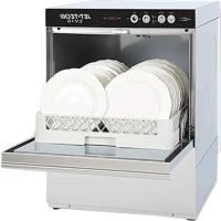
EV18 - Dishwasher Jet-Tech - Free user manual and instructions
Find the device manual for free EV18 Jet-Tech in PDF.


User questions about EV18 Jet-Tech
0 question about this device. Answer the ones you know or ask your own.
Ask a new question about this device
Download the instructions for your Dishwasher in PDF format for free! Find your manual EV18 - Jet-Tech and take your electronic device back in hand. On this page are published all the documents necessary for the use of your device. EV18 by Jet-Tech.
USER MANUAL EV18 Jet-Tech
natural_image
Technical line drawing of two industrial equipment cabinets with internal compartments and mounting feet (no text or symbols)QUICK GUIDE - GUIDE RAPIDE
text_image
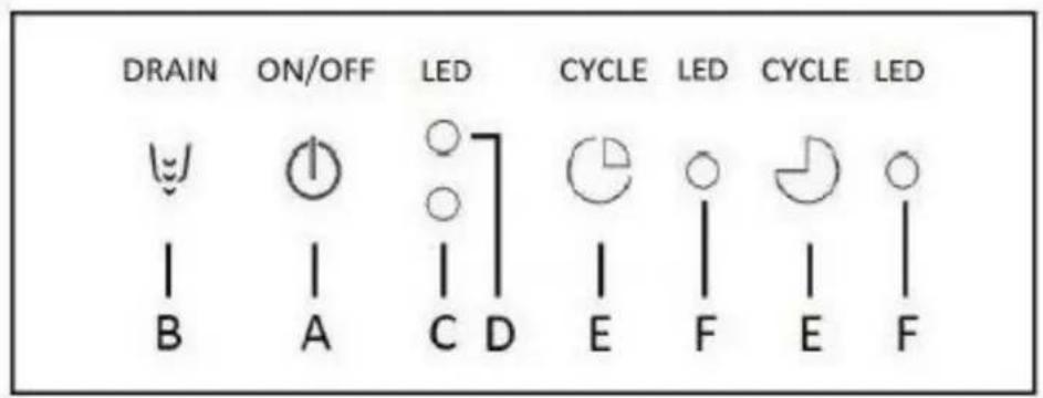
DRAIN ON/OFF LED CYCLE LED CYCLE LED B A C D E F E F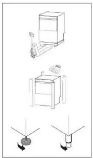
natural_image
Technical line drawings of mechanical components and a rotating component (no text or symbols)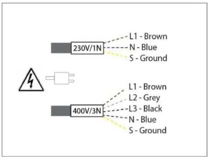
text_image
230V/1N L1 - Brown N - Blue S - Ground 400V/3N L1 - Brown L2 - Grey L3 - Black N - Blue S - GroundOPERATION - FONCTIONNEMENT
text_image
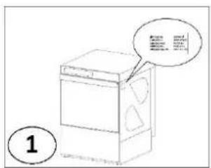
Diagram of a washing machine with speech bubble and numbered label (1) nearby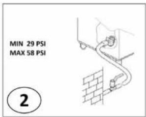
text_image
MIN 29 PSI MAX 58 PSI ②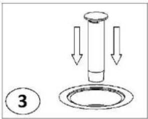
natural_image
Simple line drawing of a mechanical component with three downward arrows, no text or symbols present.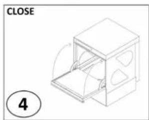
natural_image
Technical line drawing of a 3D box-like structure with internal compartments and a circular annotation labeled '4' (no text or symbols on the diagram itself)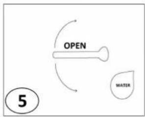
flowchart
graph TD
    A["OPEN"] --> B["WATER"]
    style A fill:#f9f,stroke:#333
    style B fill:#ccf,stroke:#333
text_image
A 6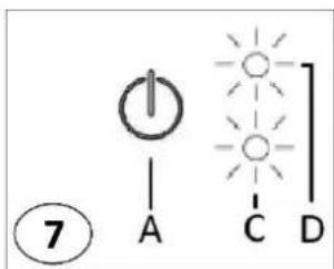
text_image
⑦ A C D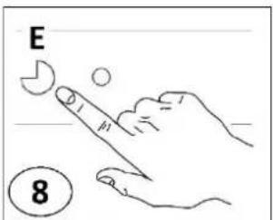
text_image
E 8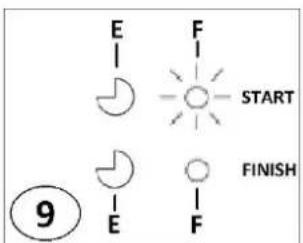
text_image
E | F | START FINISH ⑨ E | FWATER DRAIN – EVACUATION DE L'EAU
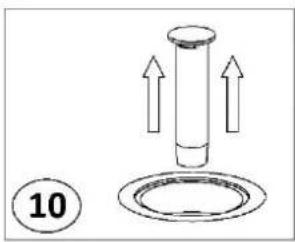
text_image
10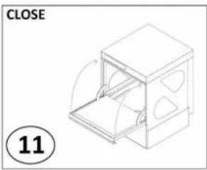
natural_image
Isometric line drawing of a 3D box with an open lid, labeled 'CLOSE' and circled number 11 (no text or symbols on the diagram itself)EV18
text_image
✓ MAX 100 mm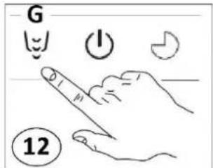
text_image
G 12EV22

natural_image
Technical diagram showing a mechanical device and a piping system with no visible text or symbols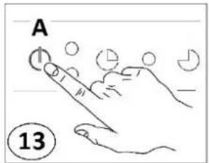
text_image
A 13

CAUTION: Read the instructions before using the appliance.
Children must not play with the appliance.
Read this instructions booklet carefully, as it contains important advice for safe installation, operation and maintenance. Keep this booklet on hand in a safe place for future reference by other operators.
Installation, use and service of the machine can be performed only by qualified personnel, especially trained to follow these instructions:
WARNING!
• The manufacturer cannot be held responsible for injuries or damages of any kind occurring to persons, machine or others, due to lack of conformity with the operation instructions indicated in this documentation or for abuse, misuse and lack of conformity with the instructions indicated in this document as well as installation, uninstall, service, tune-up, maintenance requiring the removal of the safety components not performed BY TRAINED TECHNICIANS, will result in the IMMEDIATE LOSS OF WARRANTY.
- Loss of warranty will also result from any service performed to the machine, when: Safety component are removed without disconnecting the power and water supply or when any safety provision of the machine has been bypassed, removed or excluded.
- Machine is installed in provisional, improper or unsafe conditions for lack of compliance with safety provisions (fuses, main breaker, ground line, or water inlet and discharge valves).
- When unauthorized modifications or additions of devices which modify the operation cycles indicated on the data chart delivered with the machine.
- When non-genuine spare parts are used.
• Installation or storage in inadequate spaces according to the indications of manufacturer. - Machine utilization different from the scope foreseen as written in the documentation (ex. Dishes of type or sizes different from specified).
- Utilization of dispensers with corrosive products.
1A - HANDLING
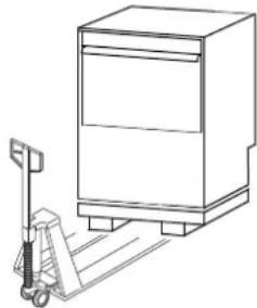
Use suitable means to move the appliance: a lift truck or fork pallet trucks (the forks should reach more than halfway underneath the appliance).
1B - UNPACKING
Before opening the box, verify the condition and indicate damages on delivery slip if found. After unpacking, check the machine's conditions, in case the machine is damaged, contact the dealer immediately.
Do not proceed with the installation if damages are relevant to operation safety. Wait for qualified and authorized assistance. Save box components (plastic bags, expanded polystyrene, nails, etc.) out of the reach of children for safety reasons.
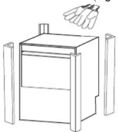
1- Wear protective gloves to unpack the appliance from the box. (Fig. 1)
natural_image
Line drawing of a cabinet with a hand holding a bottle above it (no text or symbols)Fig.1
2- Lift the appliance using a lift truck. (Fig. 2)
natural_image
Line drawing of a pallet jack next to a multi-tiered storage cabinet (no text or symbols)Fig.2
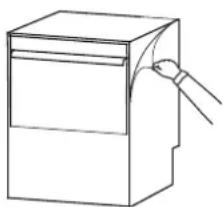
3- Remove the protection film from the appliance. (Fig. 3)
natural_image
Line drawing of a box with a handle, no text or symbols presentFig.3
1C - DISPOSAL
This appliance is marked according to the European directive 2002/96/EC on Waste Electrical and Electronic Equipment (WEEE). By ensuring this product is disposed of correctly, you will help prevent potential negative consequences for the environment and human health, which could otherwise be caused by inappropriate waste handling of this product. The symbol:
on the product, or on the documents accompanying the product, indicates that this appliance may not be treated as household waste. Instead it should be handed over to the applicable collection point for the recycling of electrical and electronic equipment. Disposal must be carried out in accordance with local environmental regulations for waste disposal.
1D - TECHNICAL DATA
WATER CONNECTION
| Temperature | °C | 50 |
| °F | 122 | |
| Pressure | kPA | 200-400 |
| Bar | 2-4 | |
| PSI | 29 - 58 | |
| Flow | Lt/min | 20 - 30 |
| Hardness | °f | 7 - 14 |
| °dH | 4 - 7,5 | |
| °e | 5 - 9,5 | |
| ppm | 70 - 140 | |
| Mineral residues | mg/l | 300 / 400 |
| Conductivity | μS/cm | 300 / 400 |
ELECTRICAL CONNECTION
| Voltage | V | ±6% |
| Frequency | Hz | ±1% |
| Wash Cycle | °C | 55 |
| Rinse Cycle | °C | 85 |
INSTALLATION ENVIRONMENT
| Operating Temperature | °C | 5 - 35 |
| °F | 41 - 95 | |
| Storage Temperature | °C | 10 - 70 |
| °F | 50 - 158 |
1D1- NOISE LEVEL
Environment noise level cannot exceed the values as per Standards of place of installation. The noise of the machine, measured at the manufacturer site, was less than 70dB, approximately 58dB.
When using the machine the following data must be complied with the storage, transportation, utilization and maintenance of the machine. This documentation can be updated and the manufacturer can reserve the rights to modify present values.
2 - INSTRUCTION FOR INSTALLER / MAINTENANCE
ATTENTION
Qualified technicians that install the machine are obliged to train the operators about machine utilization and safety procedures to be followed. They must provide a real “demonstration” and verify that machine instructions are available to the operators.
Following warnings should be noted:
The dishwasher must be installed in accordance with local codes, or in the absence of local codes, installed in accordance with the applicable requirements in the National Electrical Code, NFPA 70, Canadian Electrical Code (CEC), Part 1, CSA C22.1, and Standard for Ventilation Control and Fire Protection of Commercial Cooking Operations, NFPA 96.
WARNING!
DO NOT OPEN THE DOOR QUICKLY IF CYCLE HAS NOT ENDED.
DO NOT DIP BARE HANDS IN WASHING SOLUTION.
DO NOT TAKE OFF THE MACHINE PANELS IF THE MACHINE HAS NOT BEEN DISCONNECTED FROM THE POWER AND WATER SUPPLY.
DO NOT BYPASS THE MACHINE PROTECTIONS (MICROSWITCHES, PANELS, OR OTHERS) PROVIDED BY THE MACHINE MANUFACTURER IF NOT IN THE PRESENCE OF TRAINED TECHNICIAN THAT CAN TAKE PROPRER PRECAUTIONS.
DO NOT UTILISE THE MACHINE TO WASH OBJECT OF SHAPE, TYPE, SIZE, AND MATERIAL NOT COMPATIBLE WITH THE MACHINE.
DO NOT OPERATE THE MACHINE IF NOT PROPERLY CONNECTED, ACCORDING TO THE SPECIFICATIONS AND REQUIREMENTS OF THE LOCAL LAW AND PRESCRIPTION OF MANUFACTURER, MAKING SURE THAT ALL SAFETY DEVICES ARE OPERATIVE.
ID/RATING/DATA PLATE
ID/Rating plate of the appliance contains identification and technical data and is located on front panel.
2A - WATER CONNECTION
N.B.
Shut-off valve must be a single direction, spool, sphere, lid control type, which can shut water supply off quickly and totally. The water pressure and flow must conform to the data diagram supplied with each machine.
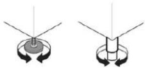
1- Position the dishwasher and level the appliance by turning the relative height-adjustable feet. (Fig.4)
natural_image
Two diagrams showing a mechanical or electrical component with rotating arrows, no text or symbols present.Fig. 4
2- Connect the solenoid valve, which feed the machine, to the water shut valve, using a flexible line. (Fig.5) Each machine must have its own water supply line.
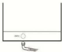
Fig. 5
2A1 - WATER SUPPLY PRESSURE
Check that dynamic water supply pressure, measured between the appliance and the main, is between 200 and 400kPa. If the pressure is too high, fit a suitable pressure reducer on the inlet pipe. If the pressure is low, install an additional external pressure motor pump. (par.1D - Technical Data)
- In case of new or long term appliance inactivity, drain the water line to eliminate air bubbles and foreign bodies present in new or unused water lines, which could damage the machine.
2A2 - WATER HARDNESS
If water hardness is higher than acceptable, install a water softener of adequate size before the feed solenoid valve. (par.1D - Technical Data)
If there is a high concentration of mineral residues in the water or high conductivity, we recommend installing the demineralization filter for 5/7° f.
2A3 - MODELS WITH GRAVITY DRAINAGE N.B.
The drainage line must comprise of a sump pit, free flow, of proper size capable to dispose twice the water flow indicated on the data diagram. It must be close to the drain pipe of the machine without bending, stretching or jointing the pipe.
- Drain line must reach sump pit with free flow without constraints, stretching, bends, kinks, or being forced.
- Connect the waste outlet pipe to the main drain pipe, fitting a trap, or place the outlet pipe over an "S" trap set into the floor.
2A4 - MODELS WITH DRAIN PUMP
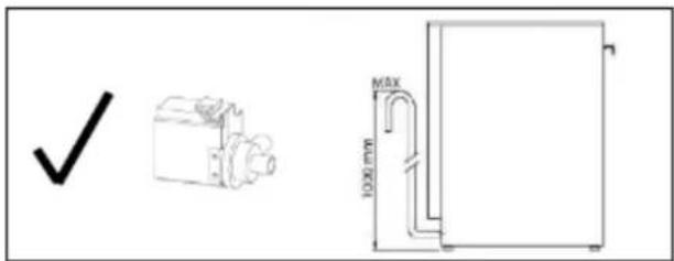
- Position the outlet pipe at a height anywhere between 30" and 40" from the floor. (Fig.6)
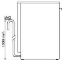
text_image
MAX 1000 mmFig. 6
2B - ELECTRICAL CONNECTION N.B.
All contacts must be mechanically open, ground line included, min. distance between contacts 3 mm, with magnetic overload or fuses, calibrated for a max, sustained current in agreement with machine date plate. It must be installed outside the machine but close to it. It must feed only one machine at time.
Machine cannot be connected to mains using adapters, plug, cables or cable extensions not properly sized and adequate to the machine's power requirements.
- Verify main specifications comply with indicated requirements on the data plate located on the front bottom panel of the machine (par. ID/RATING/DATA PLATE), that exists for the connection, a main breaker with proper size suitable for the machine and a proper ground system.
| WARNING! | ||
| THE MANUFACTURER IS NOT RESPONSIBLE FOR DAMAGES OR INJURIES CAUSED FOR IMPROPER GROUNDING. THE GROUND AND THE ELECTRICAL CONNECTIONS SHOULD BE IN COMPLIANCE WITH NATIONAL REGULATIONS. |
The line cable should be replaced with a spare cable supplied by the manufacturer. For replacement indicate machine type, machine serial number and possible modifications of the installation. Power cable cannot be stretched or kinked during normal operation.
Grounding point on machine must be connected to nearest appliance terminal according to Safety Standards.
2C - WARNING MESSAGES DISPLAYED ON THE CONTROL PANEL
N.B.
If the machine is in OFF mode, warning messages are not displayed. Turn ON the machine to visualize the type of warning message on the appliance.
Following warning messages on the display are provided:
ALR1 - WATER FILL
Water fill not completed during the available maximum time (10min).
Verify that water supply is correctly connected, opened and free of obstructions.
Verify that solenoid valve filter is free of possible obstructions and deposit.
Verify that water supply pressure is adequate (par.1D - Technical Data).
Verify that machine's door is completely closed and the overflow device is correctly positioned inside the tank.
N.B.
If water fill timing expires the solenoid valve is automatically interrupted. To restart solenoid valve press any button on the control panel.
ALR2 - DRAIN ANOMALY
Drainage not completed on the maximum programmed timing.
Verify that the overflow device is completely removed and not obstructions are present on the water drain line.
ACTIONS FOLLOWED TO THE WARNINGS:
Booster and tank heating elements are interrupted, all loads are deactivated, the electronic board displays warning codes and it is deactivated. All control panel LEDs are Off. Cycle is interrupted "hold mode" until the machine is reset. It is always possible to turn appliance Off and On using the button.
SAFETY THERMOSTAT
All machines are provided with a safety overload that shuts machine off in case of overheating (120°C/248°F). To reset the overload device press the push-button behind the control panel.
2D - DETERGENT AND RINSE AID DISPENSERS AND SETTINGS
N.B.
This machine must be operated with an automatic detergent feeder and, if applicable, an automatic chemical sanitizer feeder, including a visual means to verify that detergents and sanitizers are delivered or a visual or audible alarm to signal if detergents and sanitizers are not available for delivery to the respective washing and sanitizing systems. Please see instructions for electrical and plumbing connections located in this manual and in the feeder equipment manual.
Before starting a new cycle the dispenser and its pipe must be completely filled. Check the level of the detergent or rinse aid and if needed fill-up the tank.
N.B.
The level in the detergent or rinse aid tank must not get empty or filled with corrosive or inadequate products. The warranty does not cover damages caused by improper use of dispenser. The dispenser is calibrated at manufacturer site: dispenser settings after installation must be performed by a qualified technician.
1- Remove the front panel with Allen or similar tool by inserting it inside the holes on the interior part of the panel. Remove the panel carefully.
2- For Hoodtype models, unscrew the two screws located on the bottom of the panel. (Fig.7)
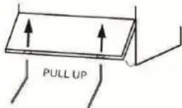
text_image
PULL UPFig.7 Before removing the front panel make sure the machine is disconnected from the main breaker.
3- Insert the included dispenser tube inside the detergent or rinse aid tank. (if available). (Fig.8)
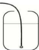
Fig.8
2D1 - PERISTALTIC RINSE AID AND DETERGENT DISPENSER
Setting of rinse aid dispenser is performed by adjusting the screw accessible after removal of front panel, under the tank door. (see Fig.8)
1- Gently Close the dispenser by screwing the needle valve of the dispenser counter clockwise.
2- Open by screwing the needle valve of the dispenser clockwise until the necessary quantity has been achieved. (Fig.9)
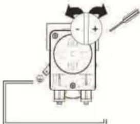
natural_image
Pure electrical circuit lines without any symbolsFig.9
Quantity for the first setting should be according to the installer after evaluating the hardness of the water and the type of rinse aid used. Recommended rinse aid standard quantity is 0,16 gr/sec that correspond to the maximum flow rate of the dispenser. Recommended detergent standard quantity is 0,77 gr/sec that correspond to the maximum flow rate of the dispenser.
SUGGESTION
To check the effectiveness of the rinse aid, look at freshly washed glasses against the light. Drops of water remaining on the glass indicate an insufficient amount while streaks indicate an excess.
In case of light coating that stop the dispenser functions, remove the coating by soaking the dishes for 30 minutes in a water soap solution (1:10) before starting machine cycle.
2E - MAINTENANCE
1- Descale the boiler, the internal surface of the tank and the appliance water piping once or twice a year.
2- Descale the rinse and wash jets every month using vinegar or a descaling agent.
3- The internal hose of the rinse aid and detergent peristaltic dispenser should undergo periodic maintenance (once or twice a year).
4- Clean solenoid valve filter by removing it from the inside of the valve and unplugging the water inlet tube.
2F – UNINSTALL (Long period of inactivity)
Machine can be taken out of operation only by trained technicians authorized for the purposes, who will provide the following:
1- Shut water line off (water valve) and electric supply (main breaker).
2- Completely drain the tank.
3- Remove and carefully clean the filters.
4- Completely drain the incorporated dispenser hoses, removing them from the containers.
5- Drain the detergent and rinse aid nozzles with fresh water first and after with water and glycerine (50% - 50%) taking care that nozzles remain clean and lubrified inside.
6- Drain the booster completely by removing the screw located under the machine.
7- Spread a thin film of vaseline oil over all the stainless steel surfaces.
INSTALLER REMARKS
INSTALLATION DATE:
INSTALLATION PLACE:
INSTALLER NAME:
MACHINE SERIAL NUMBER:
SIGNATURE:
3A - GENERAL
RECOMMENDATIONS AND
WARRANTY
Our appliances have been tested and optimised to consistently deliver high reliability and performance. This appliance must be used exclusively for the purpose for which it has been designed, i.e. for washing dishes with water and specific detergent. Any other use could potentially involve unforeseen or lethal consequence.
WARNING!
BEFORE ANY CLEANING OR MAINTENANCE OPERATION, DISCONNECT THE DISHWASHER BY SWITCHING OFF THE ELECTRICITY AT THE MAINS OR REMOVING THE PLUG.
DO NOT LEAVE THE DISHWASHER SWITCHED ON UNNECESSARILY.
IF ANY FAULT IS DETECTED, DISCONNECT THE DISHWASHER FROM THE MAINS, CLOSE THE MAIN WATER SUPPLY AND CALL FOR SERVICE ASSISTANCE.
DO NOT OPEN THE DISHWASHER DOOR BY PULLING THE TOP FRONTWARDS.
DO NOT USE THE DISHWASHER IN A EXPLOSIVE ATMOSPHERE.
DO NOT WASH OR CLEAN THE MACHINE WITH DIRECT SPRAY OF WATER AND/OR WITH ABRASIVE MATERIAL.
DO NOT EXPOSE THE MACHINE TO HEAT AND/OR HUMIDITY SOURCES.
DO NOT USE THE MACHINE IF THE SUPPLY CABLE IS DAMAGED.
THE MANUFACTURE DECLINES ANY LIABILITY FOR DAMAGES TO PERSONS AND/OR THINGS DUE AND TO IMPROPER AND/OR UNREASONABLE USE OF THE MACHINE.
NEVER CLOSE THE WATER SUPPLY WHILE THE MACHINE IS WORKING.
DO NOT DISCONNECT THE SUPPLY BY PULLING THE SUPPLY CABLE, DISCONNECT USING THE PLUG.
USE ONLY PROFESSIONAL DETERGENTS AND RINSE AID AND STORE THEM IN A COOL AND DRY PLACE, OUT OF THE REACH OF CHILDREN.
DO NOT REMOVE ANY PROTECTION AND/OR PANELS REQUIRING A TOOL TO BE REMOVED.
THE MACHINE IS EQUIPPED WITH SAFETY MICROSWITCH TO STOP THE OPERATION IN CASE THE DOOR IS OPENED DURING THE WORKING PROCESS. THE MOTOR PUMP IS EQUIPPED WITH A 160°C/320°F THERMAL PROBE TO AVOID OVERHEATING.
ELECTRICAL PARTS ARE NOT ACCESSIBLE WITHOUT USING A TOOL.
TO PREVENT VIBRATIONS, THE MACHINE IS EQUIPPED WITH FOUR ADJUSTABLE FEET.
THIS APPLIANCE CAN BE USED BY CHILDREN AGED FROM 8 YEARS AND ABOVE AND PERSONS WITH REDUCED PHYSICAL, SENSORY OR MENTAL CAPABILITIES OR LACK OF EXPERIENCE AND KNOWLEDGE IF THEY HAVE BEEN GIVEN SUPERVISION OR INSTRUCTION CONCERNING THE USE OF THE APPLIANCE IN A SAFE WAY AND HAVING UNDERSTOOD THE HAZARDS INVOLVED.
One year parts and labor warranty.
N.B.
Damages, breakdown based on lack of conformity with the operation instructions indicated in this documentation and for abuse, misuse and lack of conformity with the instructions indicated in this documentation or service by unauthorized and non specialist persons will result in the IMMEDIATE LOSS OF THE WARRANTY.
3A1- SUGGESTION BEFORE USING THE DISHWASHER
- Carry out a couple of cycles without dishes to flush out any industrial grease which has remained in the tank and piping.
- Avoid washing decorated dishes.
- Do not allow silverware to come in contact with other metals.
- Do not allow food to dry on the dishes.
- Remove large food scraps from the dishes to prevent clogging the filters.
- Pre-wash the dishes by spraying them with cold or lukewarm water, without using any detergent.
- To have best washing results place all cutlery in the cutlery basket with the handles downwards paying attention to avoid potential injuries.
- Use automatic dispenser for the detergent.
- If there is no automatic dispenser, put non-foaming detergent into tank when the water has reached the washing temperature.
3B - STANDARD LOADING RACKS
1- Load plates in frontal position. (Fig.10)
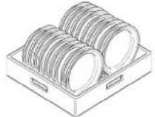
Fig.10
2- Load glasses and bowls in upside down position. (Fig.11)
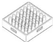
Fig.11
3- Load cutlery vertically inside its containers. (Fig.12)
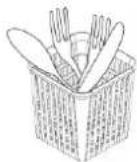
Fig.12
3- Load rack machine with dishes as described. For undercounter models load the rack front side. For hoodtype models load the rack front side or sideways (if necessary switch rack support clockwise). (Fig.13)
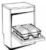
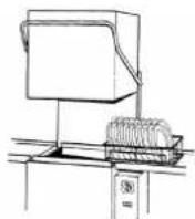
Fig.13
3C - STARTING / WASH CYCLES
CONTROL PANEL
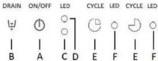
text_image
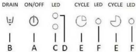
DRAIN ON/OFF LED CYCLE LED CYCLE LED B A C D E F E FLEGENDA
A = On/Off
B = Drain Water Tank
C = On Machine Indicator Light
D = Machine Ready Indicator Light
E = Start Cycle
F = Washing Cycle indicator light
N.B.
The representation of the control panel above is meant for the full version of the equipment. Some versions may not have all the indicated functions.
3C1 - STARTING THE MACHINE
1- Open the door and verify that all internal components, the water flow device included, are in the correct position. (Fig.14)
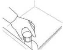
Fig.14
2- Open main water supply valve.
3- Switch on at the mains.
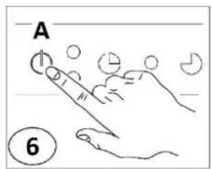
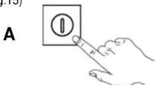
4- Close the door and press button "A" to turn ON the machine. Indicator light "C" is ON. (Fig.15)
text_image
A (I)Fig.15
- If the door is opened during carrying out the above process, the water tank filling process will be interrupted. To resume filling process close the door.
- After water heating process is complete and the right temperature is reached, the indicator light is visualized on position "D" on the machine signaling that it is READY to be used. (Fig.16)


Fig.16
3C2 - WASHING CYCLE
Washing cycle is composed of one hot cycle with detergent at 60°C (140°F) and one hot final rinse with rinse aid at 85°C (185°F).
When the machine reaches the correct temperature and it is ready to start a new cycle, indicator light is visualized on position "D", then:
1- Open the door.
2- Insert the basket with dirty dishes and close the door.
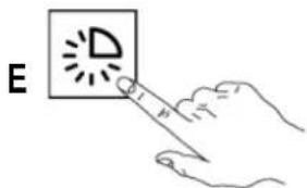
3- Press button "E" start washing cycle. Indicator light "F" is ON for the entire period of washing. (Fig.17)
text_image
EFig.17
4- On the display will appear "wash" message. (Fig.18)

Fig.18
5- Wait until indicator light "F" is OFF and on the display appear "end" message (Fig.19). Open the door and remove clean dishes basket.
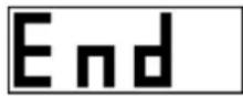
Fig.19
- If during this process door is opened, the washing cycle is interrupted until door is closed. To continue and finish washing cycle you must close the door.
WARNING!
THE APPLIANCE WILL NOT REMOVE BURNT FOOD DEPOSITS FROM DISHES. DISHES WITH BURNT-ON FOOD DEPOSITS SHOULD BE CLEANED MECHANICALLY/CHEMICALLY (FOR EXAMPLE, PRE-WASH UNDER RUNNING WATER) BEFORE PUTTING THEM IN THE DISHWASHER.
THE USE OF "FOAMING" DETERGENT AND OR IN ANY DETERGENTS USED IN DIFFERENT WAYS FROM THAT PRESCRIBED BY THE MANUFACTURER OR FAILURE TO REMOVE THE RESIDUE OF DETERGENT POSSIBLY USED FOR MANUAL 3B5 - AUTOMATIC WASH CYCLE (only machines with hood)
3C3- AUTOMATIC CYCLE (only hoodtype machines)
It is possible to carry out an automatic washing cycle by simply closing the door of the machine.
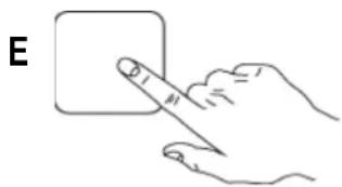
1- Press the "E" key to select the wash cycle. (Fig. 20)
natural_image
Hand holding a square object with a knife, labeled 'E' in the top-left corner (no other text or symbols)Fig.20
2- Close the door. The washing cycle will start automatically.
- The first cycle must be started by pressing the button of the washing cycle. All other cycles will be automatic.
3D – DAILY CLEANNING / END OF WORK
Cleaning and user maintenance must not be performed by children without supervision.
In order to have excellent washing results and a clean tank, it is recommended to change the water of the machine at least twice a day and clean all the filters inside the tank. Filters must be removed only once all the water is drained from the machine.
3D1 – WATER DRAIN WITHOUT DRAIN PUMP INCLUDED
1- Turn OFF the machine by pressing button "A" On/Off.
2- Open the door and remove the water flow device and close the door. (Fig.21)
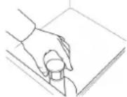
Fig.21
3D2 – WATER DRAIN WITH DRAIN PUMP INCLUDED
1- Open the door and remove the water flow device and close the door. (Fig.22)
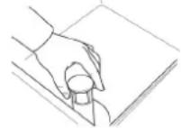
Fig.22
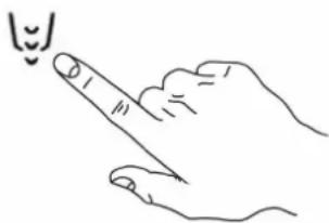
2- Press button "B" to start drain out the water and wait until all the water is completely drained out from the tank. (Fig.23)
B
natural_image
Line drawing of a hand pointing upward with a small smiley face above it (no text or symbols)Fig.23
3- On the display will appear water drain message during process. (Fig.24)
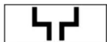
Fig.24
4- Turn OFF the machine by pressing button "A" On/Off.
3D3 - FILTERS CLEANNING
1- Turn OFF the machine by pressing button "A" On/Off.
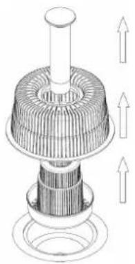
2- Manually remove the overflow and the filters. (Fig.25)
natural_image
Technical line drawing of a mechanical component with three upward arrows indicating motion or force (no text or symbols)Fig.25
3- Wash and clean filters thoroughly with running fresh water.
4- Repositionated all filters and components inside the machine.
3D4 - EXTERNAL SURFACES CLEANNING
Before carrying out any cleaning operations, turn off the power at the mains.
To reduce the emission of pollutants into the environment, clean the appliance (externally and where necessary internally) with products having a biodegradability of over 90%.
WARNING!
CLEAN STAINLESS STEEL SURFACES BY USING WARM SOAPY WATER; NEVER USE DETERGENT CONTAINING ABRASIVE SUBSTANCES NOR STEEL SCRAPERS, COMMON WIRE WOOL, OR BRUSHES; RINSE THOROUGHLY USING A WET CLOTH AND CAREFULLY WIPE DRY. DO NOT WASH THE APPLIANCE BY USING HIGH PRESSURE WATER JETS.
3D5 - TURNING OFF THE MACHINE
1- Completely drain the water from the tank.
(see par.3D1/2/3)
2- Turn OFF the machine by pressing button "A" On/Off.
3- Close the door and turn off the power at the mains.
3E – WARNING MESSAGES DISPLAYED ON THE CONTROL PANEL
N.B.
If the machine is in OFF mode, warning messages will not be visualized on the display. Turn ON the machine to visualize type of error.
The following warning messages are visualized on the display:
ALR 1 - WATER FILL
Water fill not completed during the available maximum time (10min).
Verify that water supply is correctly connected, opened and free of obstructions.
Verify that solenoid valve filter is free of possible obstructions and deposit.
Verify that water supply pressure is adequate (par.1D - Technical Data).
Verify that machine's door is completely closed and the overflow device is correctly positioned inside the tank.
N.B.
If water fill timing expires or water level signal is not respected, solenoid valve is automatically interrupted. To restart solenoid valve press any button on the control panel.
ALR 2 - DRAIN ANOMALY
Drainage not completed on the maximum programmed timing.
Verify that the overflow device is completely removed and not obstructions are present in the water drain line.
ACTIONS AFTER MACHINE ERROR:
Booster and tank heating elements are interrupted, water load is deactivated, control panel display visualizes the error and the electronic card is inactivated. All LED buttons are OFF. Washing cycle is interrupted (stanby mode) and restored if the problem is solved. It is always possible to turn OFF the machine by pressing button "A" ON/OFF, and if the problem is solved, warning messages are no longer displayed.
THE DISHWASHER DOES NOT WORK?
1- Verify main water supply inlet is correctly connected, open and free from any obstructions.
2- Verify main electrical supply is working without any electrical break in connections.
3- Verify the door is properly closed.
DISHWASHER DOES NOT WASH WELL ?
1- Verify if the filters are cleaned, if not, clean them. (see par. 3D4)
2- Verify if the washing water jets on the washing arms are not obstructed by any solid residues.
3- Verify correct amount and quality of detergent and rinse aid. (see par. 3B2/3C2)
4- Verify if the dishes are correctly loaded on the dishwasher. (see par. 3B6/3C7)
5- Washing cycle is too short. Use another cycle (if available) or repeat the washing cycle.
THE DISHES ARE NOT RINSED WELL?
1- Verify if the rinse water jets on the washing arms are not obstructed by any solid residues.
2- Verify solenoid valve filter is free from any obstructions such as lime or scale.
3- The inlet water pressure is inferior of 2 bar - 200 kPA. Install an external pressure device to ensure and increase the inlet water pressure inside the machine.
THE DISHES ARE NOT DRIED WELL?
1- Ask the rinse aid supplier to verify the instruction for the rinse aid dosing. (see par. 2D)
2- Verify if the rinse aid container is empty. If yes, fill it with rinse aid product. (see par. 2D)
3- Verify the quality and the quantity of the rinse aid used and check with the supplier. (see par. 2D)
4- Verify the rinsing temperature is between 80°C (176°F) to 90°C (194°F) degrees.
CONDENSATION ON GLASSES?
1- Verify if the rinse aid container is empty. If yes, fill it with rinse aid product. (see par. 2D)
2- Verify the quality and the quantity of the rinse aid used and check with the supplier. (see par. 2D)
3- Remove the glasses rack immediately after the end of each cycle.
STAINS ON GLASSES ?
1- Use only non foaming products for professional dishwashers.
EXCESSIVE FOAM IN THE TANK?
1- Verify washing water temperature is not less than 50^ C ( 122^ F) degrees.
2- Ask the assistance service to verify the instruction for the rinse aid dosing. (see par. 2D)
3- Ensure the tank has not been cleaned with unsuitable cleaners. Drain the tank and rinse throughly before new wash cycles.
4- If foaming detergent has been used, drain and refill the tank with water until the foam disappears.
SMEARS OR SPOTS ON THE GLASSES?
1- Ask the supplier to verify the instruction for the rinse aid dosing.
EMERGENCY
IN CASE OF FIRE A POWDER EXTINGUISHER MUST BE USED.
IN CASE OF DANGER CUT-OFF THE ELECTRICAL SUPPLY IMMEDIATELY.
The Manufacturer reserves the right to modify the data presented in this publication without notice.
INDEX
1 - CONSIGNES GÉNÉRALES...... p.17
1A - TRANSPORT.... p.17
1B - DÉBALLAGE.... p.17
1C - DESTRUCTION...... p.18
1D - DONNÉES TECHNIQUES...... p.18
2 - INSTRUCTIONS POUR L'INSTALLATEUR/TECHNICIEN AFFECTÉ À LA MAINTENANCE....p.19
2A - RACCORDEMENT HYDRAULIQUE...... p.19
2B - CONNEXION ÉLECTRIQUE...... p.20
2C - MESSAGES D'AVERTISSEMENT AFFICHÉS SUR LE TABLEAU DE CONTRÔLE.... p.20
2D - PRÉDISPOSITIONS ET DOSEURS DE PRODUITS LESSIVIEL ET DE RINÇAGE.... p.21
2E - MAINTENANCE...... p.22
2F - DEPLACEMENT (période prolongé d'inactivité)...... p.22
3 - INSTRUCTIONS POUR L'UTILISATEUR.... p.23
3A - AVERTISSEMENTS GENERAUX ET GARANTIE.... p.23
3B - CHARGEMENT DES PANIERS EN DOTATION.... p.24
3C - MISE EN SERVICE / CYCLE DE LAVAGE.... p.24
3D - NETTOYAGE / FIN DE SERVICE...... p.25
3E - MESSAGES D'AVERTISSEMENT AFFICHÉS SUR LE TABLEAU DE CONTRÔL.... p.26
4 - DÉCÈLEMENT DES PANNES...... p.27
CONSIGNES
natural_image
Line drawing of a cabinet with handles and vertical supports (no text or symbols)Fig.1
natural_image
Line drawing of a pallet jack and a multi-tiered storage cabinet (no text or symbols)Fig.2
natural_image
Line drawing of a box with a hand inserting a leaf (no text or symbols)Fig.3
1C - DESTRUCTION
natural_image
Two diagrams showing a mechanical or electrical component with arrows indicating rotation, no text or symbols present.Fig. 4
natural_image
Pure electrical circuit lines without any symbolsnatural_image
Technical line drawings of two industrial machines, one open with cylindrical components and the other with a tray (no text or symbols)Fig.13
3C - MISE EN SERVICE/CYCLE DE LAVAGE
TABLEAU DE CONTRÔLE
text_image
DRAIN ON/OFF LED CYCLE LED CYCLE LED B A C D E F E FNOMENCLATURE
A = Marche/Arrêt
B = Vidange
C = Voyant de machine allumé
natural_image
Line drawing of a hand pointing upward with a small smiley face above it (no text or symbols)Fig.23
natural_image
Technical line drawing of a mechanical component with upward arrows indicating motion or force (no text or symbols)Fig.25