EZPREM Kit - Lens Angénieux - Free user manual and instructions
Find the device manual for free EZPREM Kit Angénieux in PDF.

User questions about EZPREM Kit Angénieux
0 question about this device. Answer the ones you know or ask your own.
Ask a new question about this device
Download the instructions for your Lens in PDF format for free! Find your manual EZPREM Kit - Angénieux and take your electronic device back in hand. On this page are published all the documents necessary for the use of your device. EZPREM Kit by Angénieux.
USER MANUAL EZPREM Kit Angénieux
January 2017: © ANGENIEUX. Photos and illustrations are not contractual. The data is provided for information. ANGENIEUX reserves the right to modify the performance of its products without prior notice. This document is the exclusive and sole property of ANGENIEUX. Any reproduction, rights of reproduction, translation, modification, publication on a physical or digital medium, partial or complete, is strictly forbidden.
natural_image
Pure technical line drawing of a mechanical component with no text or symbolsInterchangeable to 45-135 mm T3
TYPE EZ2 PACK
15-40 mm T2
natural_image
Pure technical line drawing of a mechanical component with no text or symbolsInterchangeable to 22-60 mm T3
TYPE EZ3 PACK
45-165 mm T2.3
natural_image
Technical line drawing of a mechanical component with threaded ends and a flanged base (no text or symbols)Interchangeable to 68-250 mm T3.5
MANUEL UTILISATEUR FRANCAIS Table des matières
| 1 - PRECAUTIONS D'USAGE 7 | |
| 2 - CONFIGURATION 8 | |
| 3 - INSTALLATION SUR CAMERA ET ACCESSORISATION | 11 |
| 3.1 - Installation 11 | |
| 3.2 - Accessoires 11 | |
| 3.3 - Réglages utilisateurs 11 | |
| 4 - CHANGEMENT DE MONTURE | 13 |
| 5 - CONVERSION S35 FF/Vista Vision | 13 |
| 6 - EZ3 CONVERSION PIED/METRE | 15 |
| 7 - MAINTENANCE | 15 |
| 7.1 - Maintenance avancée | 16 |
| 7.2 - Nettoyage des lentilles | 16 |
| 7.3 - Graissage | 16 |
| 7.4 - Humidité | 16 |
| 8 - NUMEROS DE PRODUIT | 16 |
1 - PRECAUTIONS D'USAGE
line
Granure bague hits Full Frame T-stop Ramping | X-axis (min) | Y-axis | |---|---| | 68 | 3.5 | | 85 | 4.5 | | 100 | 5.6 | | 150 | 6.3 | | 200 | 7.1 | | 250 | 8.0 |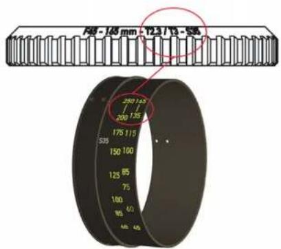
3 - INSTALLATION SUR CAMERA ET ACCESSORISATION
3.1 Installation
6 EZ3 CONVERSION PIED/METRE
7 MAINTENANCE
MAINTENANCE AVANCEE
France and International customer support at : angenieuxservice@fr.thalesgroup.com
America customer support at :
Bandpro
service@bandpro.com
Asia customer support at :
Jebsen
JCineCast@jebsen.com
USER MANUAL Contents
| 1 - PRECAUTIONS FOR USE 17 | |
| 2 - CONFIGURATION 18 | |
| 3 - CAMERA INSTALLATION AND ACCESSORIZATION 2 | |
| 3.1 - Installation 21 | |
| 3.2 - Accessories 21 | |
| 3.3 - User settings 21 | |
| 4 - CHANGE OF MOUNTING 23 | |
| 5 - CONVERSION S35 FF/Vista Vision 23 | |
| 6 - EZ3 FEET / METER CONVERSION 25 | |
| 7 - MAINTENANCE 25 | |
| 7.1 - Advanced Maintenance | 26 |
| 7.2 - Cleaning the lenses | 26 |
| 7.3 - Lubrication | 26 |
| 7.4 - Humidity | 26 |
| 8 - PRODUCT NUMBERS | 26 |
1 - PRECAUTIONS FOR USE
Read this manual carefully
Warnings
Do not look at a light source directly through the lenses Handle the lens carefully
Do not put the lens in contact with water
Storage conditions
Store the lens in a dry place where the temperature is between -40^ and +70^ .
Temperature
• The lens is designed to be used between -20^ et +45^ .
- A change in temperature may cause a sight shift in focus
Advanced Maintenance
Complete maintenance of this type of objective can only be carried out by highly qualified personnel. We recommend that you contact us to have your lens serviced (see Advanced maintenance page 20)
Recycling and Environment
The lenses do not contain any chemical substance covered by the European REACH Regulation in proportions exceeding the defined thresholds.
Holding zoom on the camera
In order to take the full quality advantage of your new lens, Angenieux preconize to systematically use intermediate bracket in order minimize the constraints on the camera mount.
2 - CONFIGURATION
This user manual describes the following products :
- Zoom EZ1 Pack (foot or meter)
- Zoom EZ2 Pack (foot or meter)
- Zoom EZ3 Pack (foot or meter)
The configuration of the EZ1 Pack allows, via a change of the FF / Vista Vision rear subassembly and clamping rings, to switch from an EZ1-S35 PL (30-90) zoom to a FF (45-135 zoom)
The configuration of the EZ2 Pack makes it possible to change the FF / Vista Vision rear subassembly and clamping rings from a zoom EZ2-S35 PL (15-40) to a zoom FF (22-60)
The configuration of the EZ3 Pack makes it possible to change the FF / Vista Vision rear subassembly from a zoom EZ3-S35 PL (45-165) to a zoom FF (68-250)
The zoom box EZ1/EZ2 (foot or meter) includes:
• A zoom type EZ1/ EZ2 - S35 PL
• An optical rear group FF/VV
• An iris engraved ring
• A focal information red ring
- A shim set
- Two Lens brackets support
The zoom box EZ3 includes :
• A zoom type EZ3 – S35 PL
• An optical rear group FF/VV
- A shim set
- Two intermediate bracket
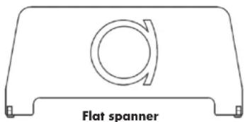
- A flat spanner for removing the front cover
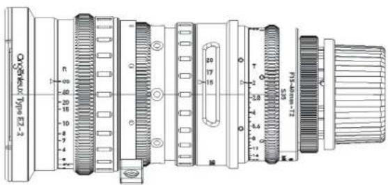
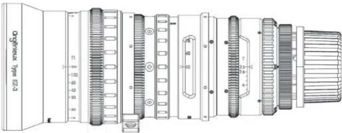
General view
For illustrations, please see FIGURE 1 at the end of the user manual
| Reference | Description Quantity | |
| 1 Front | cap 1 | |
| 2 Fixed | focus mark 1 | |
| 3 Engraved | focus ring 1 | |
| 4 Focus | rubber ring 1 | |
| 5 Support | 1 | |
| 6 Zoom | rubber ring 1 | |
| 7 Zoom | mark window 1 | |
| 8 Engraved | iris ring 1 | |
| 9 Red | ring 1 | |
| 10 PL | mount sub-assembly 1 | |
| 11 Rear | cap | 1 |
Technical specification
Type EZ1 S35 (Standard)
| S35-3 perf FF/Vista Vision | ||
| Imaging coverage Up to 30.4 mm Up to 46.3 mm | ||
| Zoom ratio 3x 3x | ||
| Focal length 30 - 90 mm 45 - 135 mm | ||
| Aperture f/1.9 - T2.0 F/2.8 - T3.0 | ||
| MOD 2ft - 0.6 m 2ft - 0.6 m | ||
| Reference image size 24x13.5 37.7x24.9 | ||
| Horizontal angular FOV 43.6° - 15.2° | 45.6° - 15.9° | |
| Vertical angular FOV | 25.1° - 8.8° | 30.8° - 10.7° |
| FOV at MOD at focal min | 334 x 184 mm | 351 x 228 mm |
| FOV at MOD at focal max | 110 x 63 mm | 115 x 77 mm |
| Front diameter | 114 mm | 114 mm |
| Length | 226 mm | 226 mm |
| Weight | 4.7 lb - 2.15 kg | 4.5 lb - 2.05 kg |
Type EZ2 (Wide)
| S35-3 perf FF/Vista Vision | ||
| Imaging coverage Up to 30.4 mm Up to 46.3 mm | ||
| Zoom ratio | 2.7x | 2.7x |
| Focal length 15 - 40 mm | 22 - 60 mm | |
| Aperture f/1.9 - T2.0 F/2.8 - T3.0 | ||
| MOD 2ft - 0.6 m 2ft - 0.6 m | ||
| Reference image size 24x13.5 37.7x24.9 | ||
| Horizontal angular FOV 77.6° - 33.7° 80.2° - 35° | ||
| Vertical angular FOV | 44.5° - 19.6° 57.4° - 24° | |
| FOV at MOD at focal min | 628 x 342 mm | 658 x 426 mm |
| FOV at MOD at focal max | 235 x 134 mm | 245 x 145 mm |
| Front diameter | 114 mm | 114 mm |
| Length | 210 mm | 210 mm |
| Weight | 4.7 lb - 2.12 kg | 4.6 lb - 2.07 kg |
Technical specification
Type EZ3 S35 (Tele)
| S35-3 perf FF/Vista Vision | ||
| Imaging coverage Up to 30.4 mm Up to 46.3 mm | ||
| Zoom ratio 3.7x 3.7x | ||
| Focal length 45 165 mm 68 250 mm | ||
| Aperture f/2.3 - T3.0 F/3.5 - T4.5 | ||
| MOD 4ft - 1.2 m 4ft - 1.2 m | ||
| Reference image size 24x13.5 mm^2 37.7x24.9 mm^2 | ||
| Horizontal angular FOV 30° - 8.4° 31.1° - 8.6° | ||
| Vertical angular FOV | 16.8° - 4.8° 20.5° - 5.8° | |
| FOV at MOD at focal min | 549 x 150 mm^2 | 570 x 154 mm^2 |
| FOV at MOD at focal max | 303 x 80 mm^2 | 370 x 103 mm^2 |
| Front diameter | 114 mm | 114 mm |
| Length | 265 mm | 265 mm |
| Weight | 5.7 lb - 2.6 kg | 5.7 lb - 2.6 kg |
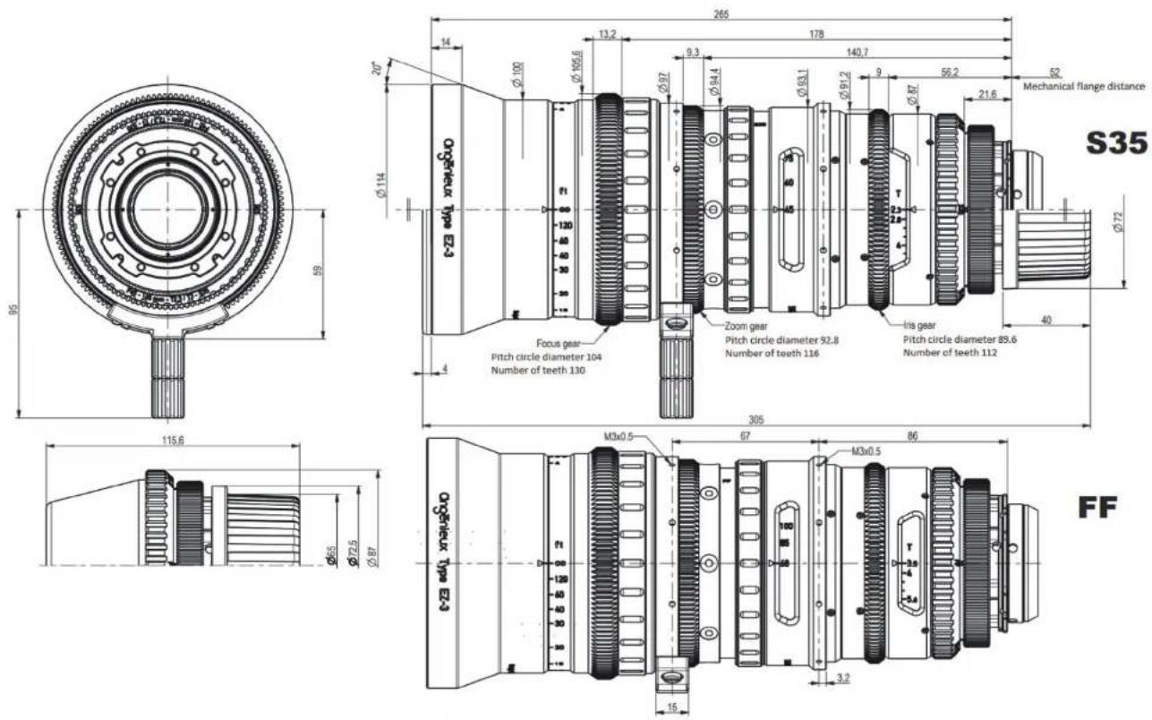
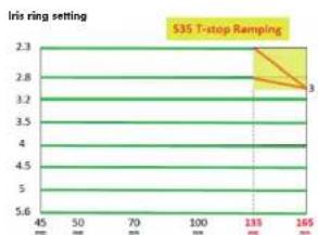
EZ3 particular specification
Les EZ-3 have a linear ramping :
• From F135mm in S35 (max ramping at F165 : 2/3 T-Stop)
• From F200mm in FF (max ramping at F250 : 2/3 T-Stop)
The ramping is only here when the aperture is under T3 (S35) or T4.5 (FF). The rest of the time the EZ-3 have a constant aperture.
line
| x | y | | ---- | ---- | | 130 | 3.0 |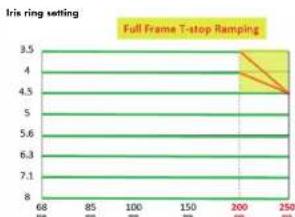
line
| X | Y | | ---- | ---- | | 68 | 3.5 | | 85 | 4.0 | | 100 | 4.5 | | 150 | 5.0 | | 200 | 5.6 | | 250 | 6.3 | | 250 | 7.1 |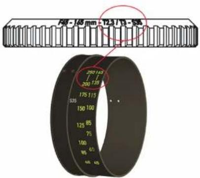
3 - INSTALLATION ON CAMERA AND ACCESSORIZATION
3.1 Installation
- Remove the rear cap (11)
• Make sure the rear element is clean - Mount the zoom on stand with standard support
- Make sure the camera mount and the lens mount match and are clean
- Locate the index finger on the camera
- Align the index of the zoom lens with the index of the camera
- Insert the lens into the camera mount and lock the camera mount
- Remove the front cap (1)
• Install other optional accessories
3.2 Accessories
The lenses of the EZ-Series Type family are delivered as standard with a PL mount.
Optionnal frames can be purchased separately :
• 0320810 : E mount
• 0320811 : EF mount
• 0320812 : PL mount
• 66069850AA : RF mount
Motors developed by MOVCAM are also available :
• 0321114 : MSU-1 (3 motors, iris, focus and focus)
• 0321116 : MSU-1A (1 focal motor)
3.3 User settings
Warnings :
Perform all user adjustments in a clean and dry place.
Use the specified tools.
Pay attention to the optical and mechanical elements when handling them to avoid degradation.
3.3.1 Flange/Back-focus adjustment
Although the mechanical flange is factory set for standard PL-mount at 52.00mm in the air, the flange can be adjusted to fit more accurately to the position of the sensor on the camera by modifying the thickness of the flange shim.
The flange can be adjusted using a collimator or a projector. When using a projector, proceed as follows:
- Mount the lens on a projector with a PL-mount tester
- Put the projector at a distance of about 1.8m from the screen
- Set the iris at full aperture
- Optimize the focus at long focal length.
- Then zoom to wide angle:
- If the best focus plan is between the screen and the lens, it is necessary to decrease the thickness of the shim
- If the best focus plan is behind the screen, it is necessary to increase the thickness of the shim.
To replace the flange shim : (see FIGURE 2)
- Unscrew the PL mount (1) and remove it (2)
- Unscrew the nut of the washers (3) with an adjustable wrench
- Remove the washer (4)
- Changing the thickness of the chock
- Place the chock (5) and fit the nut (6)
• Reassemble the PL mount (7) (8)
3.3.2 Tracking adjustment
Tracking corresponds to the difference in pointing of the optical axis between the short focal length and the long focal length.
This parameter can be evaluated in projection or on camera by pointing a fixed object at the center of the image.
To evaluate the tracking, place it in short focal length and note the position of the center of the image. Go to long focal length and note the difference in position of the center of the image.
To adjust the tracking setting, perform the following actions: (see FI-GURE 3 at the end of the manual.
- Unscrew the PL mount (1) and remove it (2)
- Remove the red ring using a Phillips screwdriver (3 screws) (3)
- Remove the retaining nut of the draft shim and the shim (4)
- Loosen without removing the 6 hexagonal screws 1.5mm placed behind the shim (5)
- The tracking adjustment is made by playing on the 4 hexagonal screws of 0.9mm placed at the periphery of the lens (6)
• Reassemble the shim, and its holding nut (7)
• Reassemble the PL mount (8) - Adjust tracking
• Disassemble the PL mount - Remove the shims and tighten the 6 hexagonal screws 1.5mm
- Reassemble the shims and reinstall the red ring (9)
• Reassemble the PL mount (10) (11)
For EZ3 :
Do the same as EZ1 and EZ2 without doing step (3) and (9): adjustment is accessible without removing the red ring. The tracking adjustment is made by playing on the 4 hexagonal screws of 0.9 mm placed at the periphery of the lens (see FIGURE 4 at the end of the manual).
4 REPLACEMENT OF MOUNT
The procedure described below provides the information needed to change the camera mount of an EZ-Series lens. It is independent of the image format of the lens (S35 ou FF/ Vista Vision).
Warnings :
- Carry out the change of frame in a clean and dry place.
- Pay attention to optical and mechanical elements when handling them to avoid any degradation.
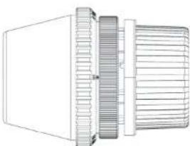
Changing the mount doesn't require any tool. For illustrations, refer to the FIGURE 5 at the end of the manual.
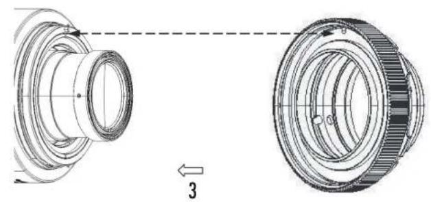
• Unscrew the mounting ring (1)
• Gently remove the mount from the rear (2)
- Position the new mount with careful orientation. The hole on the mounting face must face the indexing pin (3)
- With a sight twist, check that the new mount is in place
- Screw the retaining ring of the new mount (4)
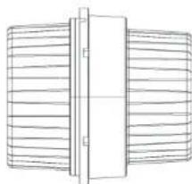
5 CONVERSION S35 ↔ FF/Vista Vision
The conversion procedure described below provides the information needed to transform an EZ-Series S35 lens into EZ-Series FF / Vista Vision lens and vice versa. This procedure is only applicable if you have an EZ-Series package. The rear optics S35 and FF / VistaVision are factory set and paired with the optics. They have the same serial number. Always use the corresponding optical blocks on the lens body.
Warnings :
- Carry out the change of the optical rear in a clean and dry place.
- Pay attention to optical and mechanical elements when handling them to avoid any degradation.
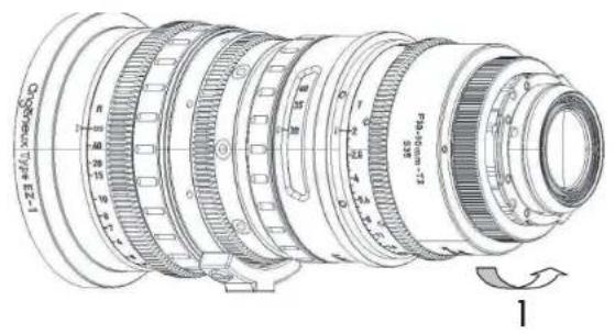
For illustrations, refer at the end of the manual, to FIGURE 6 for EZ1 and EZ2, refer to FIGURE 7 for EZ3 :
Procedure for EZ1 and EZ2 :
- Before starting the procedure, make sure that you have all the necessary parts: EZ-Series lens and optical rear with the same serial number, engraved iris ring, red focal marking ring, Phillips screwdriver, hexagon key of 1, 5mm.
- Position the lens vertically on your work table.
- Bring the iris to mechanical stop on the side of the smallest opening (T22 or T32)
- Unscrew the protective caps of the rear block to be fitted
- Unscrew the mounting ring and remove the mount from the rear (1) (2)
-
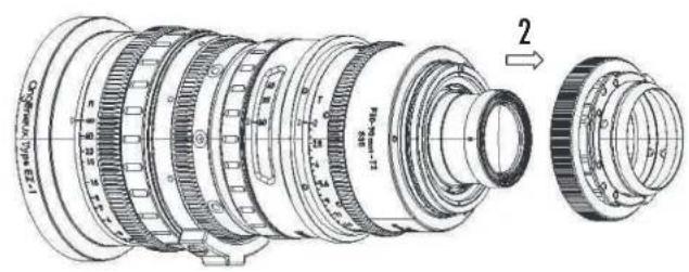
Using a Phillips screwdriver, unscrew the 3 retaining screws of the red ring (3) and remove the ring (4)
-
Using a hexagonal wrench (1.5mm), unscrew the 6 screws of the optical unit (5) and gently remove it (6) using the rear protective cap of the optical unit and taking care not to hurt it on the mechanics of the lens nor on the work table.
- Using a Phillips screwdriver, unscrew the 6 screws from the iris ring (7) and remove it from the back of the lens (8).
- Now slide the corresponding engraved iris ring to the optical unit to be installed and screw it onto the lens body with the previous 6 screws. Check its position by turning the ring gently from stop to stop.
- Carefully position the new rear optical unit with the index pin. Reassemble the 6 hexagon screws.
- Reassemble the red ring
- Reassemble the rear mount
- Slide the rubber of the focal ring onto the front of the lens (9) to release the three retaining screws of the ring
- Unscrew the three screws (10) and slide the ring up or down to display the corresponding focal length engravings at the rear group (11)
- Screw the focus ring back in place and return the rubber to the focal ring.
Procedure for EZ3 (FIGURE 7):
- Place the rear FF next to the EZ3 and remove the rear protective cap (1)
- Unscrew the red retainer(2)
- Remove the rear S35 from the EZ3 (3) and put the rear FF
- Unscrew the x4 iris witness mark ring maintaining screws (4)
- Rotate the iris mark ring at 180^ (5), in order to reveal the FF engraving
- Screw the x4 iris witness mark ring maintaining screws (4)
- Remove the zoom rubber ring (6)
- Unscrew the x3 zoom witness mark ring maintaining screws (7)
- Drag the zoom witness mark ring (8) in order to reveal the FF engraving
- Screw the x3 zoom witness mark ring maintaining screws (7)
- Put the zoom rubber ring (6)
- Put the rear protective cap on the rear S35
Video link :

6 EZ3 FEET / METER CONVERSION
The following procedure describe the conversion from a feet EZ3 to a meter EZ3. For illustrations, refer at the end of the manual, to FIGURE 8:
- Remove the front cover (1) thanks to the flat retainer
• Unscrew the x6 front ring screws (2) - Remove the front ring (3)
- Remove the focus rubber ring (4)
- Unscrew the x3 focus engraved ring maintaining screws (5)
- Remove the focus engraved ring, and flip it 180^ (6)
- Put the focus engraved ring in place and align it thanks to the infinity extension line in the hole provided for this purpose (7)
- Screw the x3 focus engraved ring maintaining screws (8)
- Put the focus rubber ring (9)
- Put the front ring (10)
- Screw the x6 front ring screws (11)
- Put the front cover (12) thanks to the flat retainer
Video link :

7 MAINTENANCE
The complete maintenance of such a lens should be performed by highly qualified people or factory trained technicians.
If you are uncertain of your capabilities to do the repair, feel free to send the lens to our After Sales Service. Our qualified technician will ensure proper handling of all maintenance and repair related items.
Please contact us at :
France and International customer support at : angenieuxservice@fr.thalesgroup.com
America customer support at :
Bandpro
service@bandpro.com
Asia customer support at :
Jebsen
JCineCast@jebsen.com
7.1 Cleaning
For maximum image quality, check the lens cleanliness regularly. If a large amount of dust is on the lenses, use a blower system before cleaning to remove them.
Use an optical cloth and an isopropyl alcohol liquid. For optimum cleaning, start at the center and clean by turning outwards
7.2 Lubrication
The zoom, focus and iris mechanisms are factory lubricated. If the lens has been stored for a long time or when used in cold environment, move each function several times before using the lens.
7.3 Humidity
To prevent humidity getting inside the lens, protect the lens to keep it dry.
8 PRODUCT NUMBERS
| Item number | Description |
| 0320800 | EZ1 Pack (feet) |
| 0320801 | EZ1 Pack (meter) |
| 0320804 | EZ2 Pack (feet) |
| 0320805 | EZ2 Pack (meter) |
| 66070827AA | EZ3 Pack (meter and feet) |
| 0320810 | EZ E - Mount |
| 0320811 | EZ EF - Mount |
| 0320812 | EZ PL - Mount |
| 66069850AA | EZ RF - Mount |
| 0321114 | MSU1 |
| 0321114 | MSU1A |
取扱説明書 内容
natural_image
Simple line drawing of a rectangular frame with a circular hole and side connectors (no text or symbols)スパナー
技術仕様
7- メンテナンス
7. 高度なメンテナンス
natural_image
Simple line drawing of a rectangular object with a circular hole and curved arrow, no text or symbols present.平头扳手
技术规格
EZ1 S35(标准)
| S35-3 perf | FF/Vista Vision | |
| 成像圈 | 至30.4mm | 至46.3mm |
| 变焦倍数 | 3x | 3x |
| 焦距 | 30-90 | 45 - 135 |
| 光圈 | f/1.9 - T2.0 | f/2.8 - T3.0 |
| MOD 最近对焦距离 | 2ft - 0.6m | 2ft - 0.6m |
| 参考成像尺寸 | 24 x 13.5 | 37.7 x 24.9 |
| 水平视角 | 43.6^ - 15.2^ | 45.6^ - 15.9^ |
| 垂直视角 | 25.1^ - 8.8^ | 30.8^ - 10.7^ |
| 视角尺寸(广角端最近焦) | 334 x 184 mm | 351 x 228 mm |
| 视角尺寸(长焦端最近焦) | 110 x 63 mm | 115 x 77 mm |
| 前口径 | 114 mm | 114 mm |
| 长度 | 226 mm | 226 mm |
| 重量 | 4.7lb - 2.15kg | 4.5lb - 2.05kg |
EZ2(广角)
| S35-3 perf | FF/Vista Vision | |
| 成像圈 | 至30.4mm | 至46.3mm |
| 变焦倍数 | 2.7x | 2.7x |
| 焦距 | 15-40 | 22 - 60 |
| 光圈 | f/1.9 - T2.0 | f/2.8 - T3.0 |
| MOD 最近对焦距离 | 2ft - 0.6m | 2ft - 0.6m |
| 参考成像尺寸 | 24 x 13.5 | 37.7 x 24.9 |
| 水平视角 | 77.6^ - 33.7^ | 80.2^ - 35^ |
| 垂直视角 | 44.5^ - 19.6^ | 57.4^ - 24^ |
| 视角尺寸(广角端最近焦) | 628 x 342 mm | 658 x 426 mm |
| 视角尺寸(长焦端最近焦) | 235 × 134 mm | 245 × 145 mm |
| 前口径 | 114 mm | 114 mm |
| 长度 | 210 mm | 210 mm |
| 重量 | 4.7lb - 2.12kg | 4.6lb - 2.07kg |
技术规格
EZ3 S35(长焦)
| S35-3 perf | FF/Vista Vision | |
| 成像圈 | 最大30.4mm | 最大46.3mm |
| 变焦倍数 | 3.7x | 3.7x |
| 焦距 | 45-165 mm | 68-250 mm |
| 光圈 | T2.3/T3 | T3.5/T4.5 |
| MOD 最近对焦距离 | 4ft - 1.2m | 4ft - 1.2m |
| 参考成像尺寸 | 24 x 13.5 mm^2 | 37.7 x 24.9 mm^2 |
| 水平视角 | 30^ - 8.4^ | 31.1^ - 8.6^ |
| 垂直视角 | 16.8^ - 4.8^ | 20.5^ - 5.8^ |
| 视角尺寸(广角端最近焦) | 549 x 150 mm^2 | 570 x 154 mm^2 |
| 视角尺寸(长焦端最近焦) | 303 x 80 mm^2 | 370 x 103 mm^2 |
| 前口径 | 114 mm | 114 mm |
| 长度 | 265 mm | 265 mm |
| 重量 | 5.7lb / 2.6kg | 5.7lb / 2.6kg |
EZ3规格参数
FIGURE 3 - EZ1 & EZ2 TRACKING ADJUSTMENT
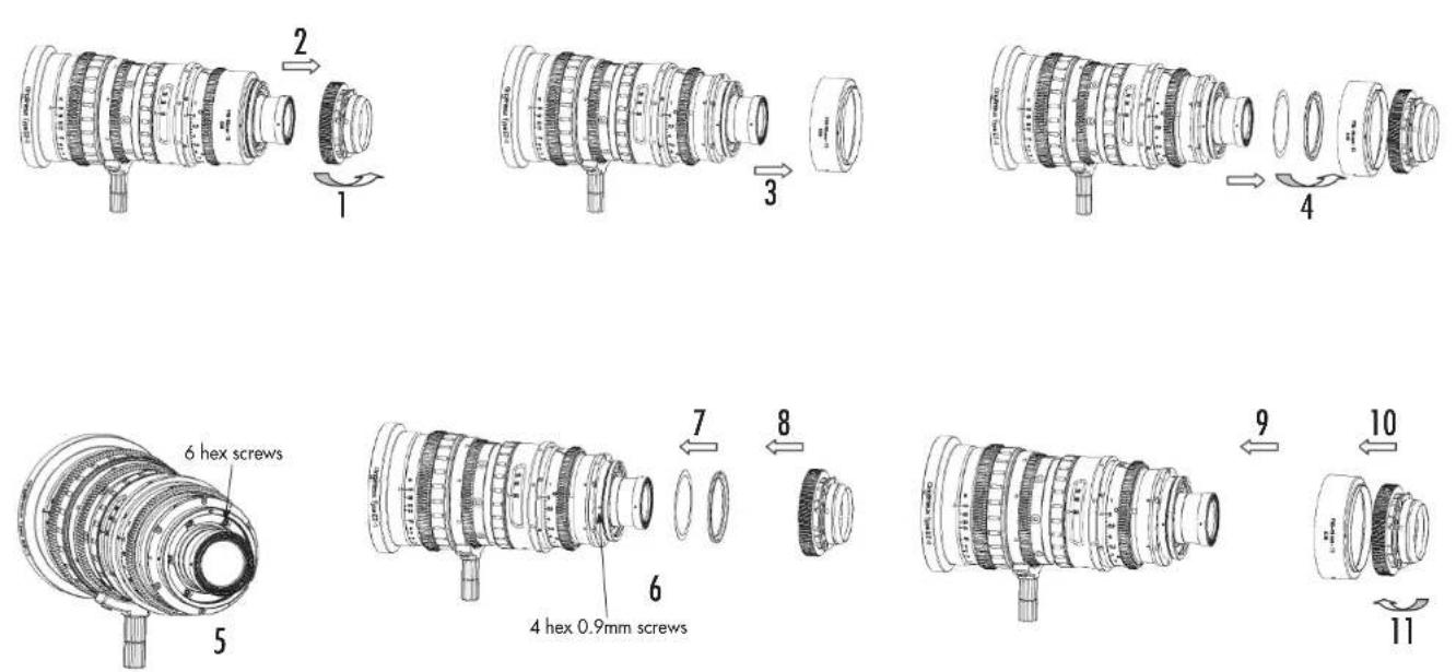
FIGURE 4 - EZ3 TRACKING ADJUSTMENT
FIGURE 5 - REPLACEMENT OF MOUNT
natural_image
Technical diagram of a mechanical component with two views, showing alignment and assembly (no text or symbols)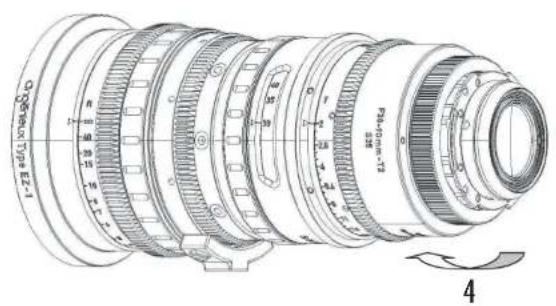
FIGURE 6 - EZ1 & EZ2 : S35 ↔ FF / VISTA VISION
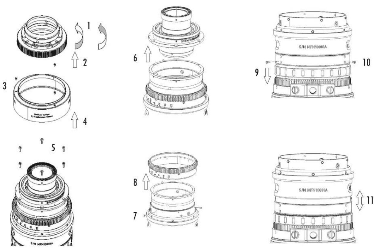
FIGURE 7 - EZ3 : S35 ↔ FF / VISTA VISION
FIGURE 8 - EZ3 FEET TO METER CONVERSION
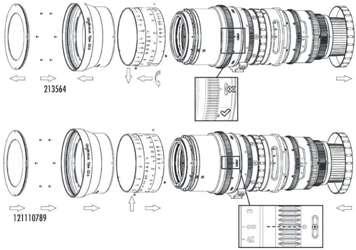
FIGURE 9 - EZ1 OUTLINE
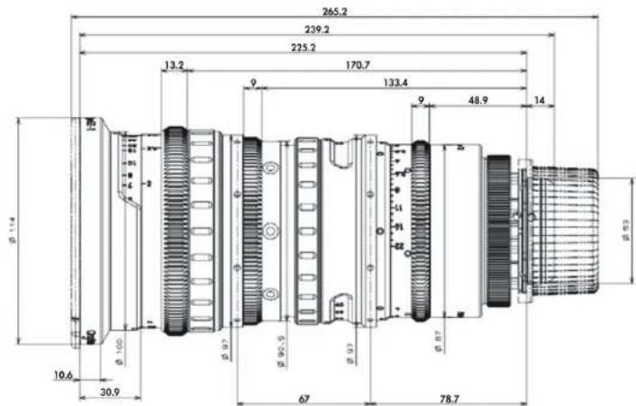
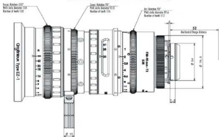
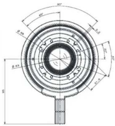
FIGURE 10 - EZ2 OUTLINE
FIGURE 11 - EZ3 OUTLINE