
CU0920X - Ice Maker Scotsman - Free user manual and instructions
Find the device manual for free CU0920X Scotsman in PDF.
| Product Type | Commercial Ice Machine with Storage |
| Brand | Scotsman |
| Model | CU0920X |
| Dimensions (W x D x H) | 51 x 60.3 x 81.1 cm (20 x 23.7 x 31.94 inches) |
| Power Supply | 115 V / 60 Hz / 1 phase, 5.9 A, max HACR fuse |
| Water Connection | 1/4 in (6.35 mm) OD flexible tube, cold potable water |
| Water Pressure | Dynamic min 1 bar (15 psi), static max 5.5 bar (80 psi) |
| Ambient Temperature | Min 10 °C (50 °F), max 38 °C (100 °F) |
| Water Temperature | Min 4.5 °C (40 °F), max 38 °C (100 °F) |
| Refrigerant | R290 (propane) - flammable |
| Production Capacity | Approximately 14-19 minutes per cycle (depending on conditions) |
| Storage Bin Capacity | Fills in about 10-12 hours (hot bin empty) |
| Settings | Adjustable ice bridge thickness and harvest time |
| Maintenance | Descaling and disinfection recommended 2 times per year |
| Condenser Cleaning | Vacuum with brush, avoid damaging fins |
| Safety | R290 flammable, installation by qualified personnel, fire extinguisher recommended |
| Warranty | See separate document, covers material/workmanship defects |
| Spare Parts | Use only genuine Scotsman parts |
| Repairability | Requires R290 certified technician |
Frequently Asked Questions - CU0920X Scotsman
User questions about CU0920X Scotsman
0 question about this device. Answer the ones you know or ask your own.
Ask a new question about this device
Download the instructions for your Ice Maker in PDF format for free! Find your manual CU0920X - Scotsman and take your electronic device back in hand. On this page are published all the documents necessary for the use of your device. CU0920X by Scotsman.
USER MANUAL CU0920X Scotsman
Installation and User's Manual for Cube Ice Machines with Storage Models CU0415X, CU0715X and CU0920X
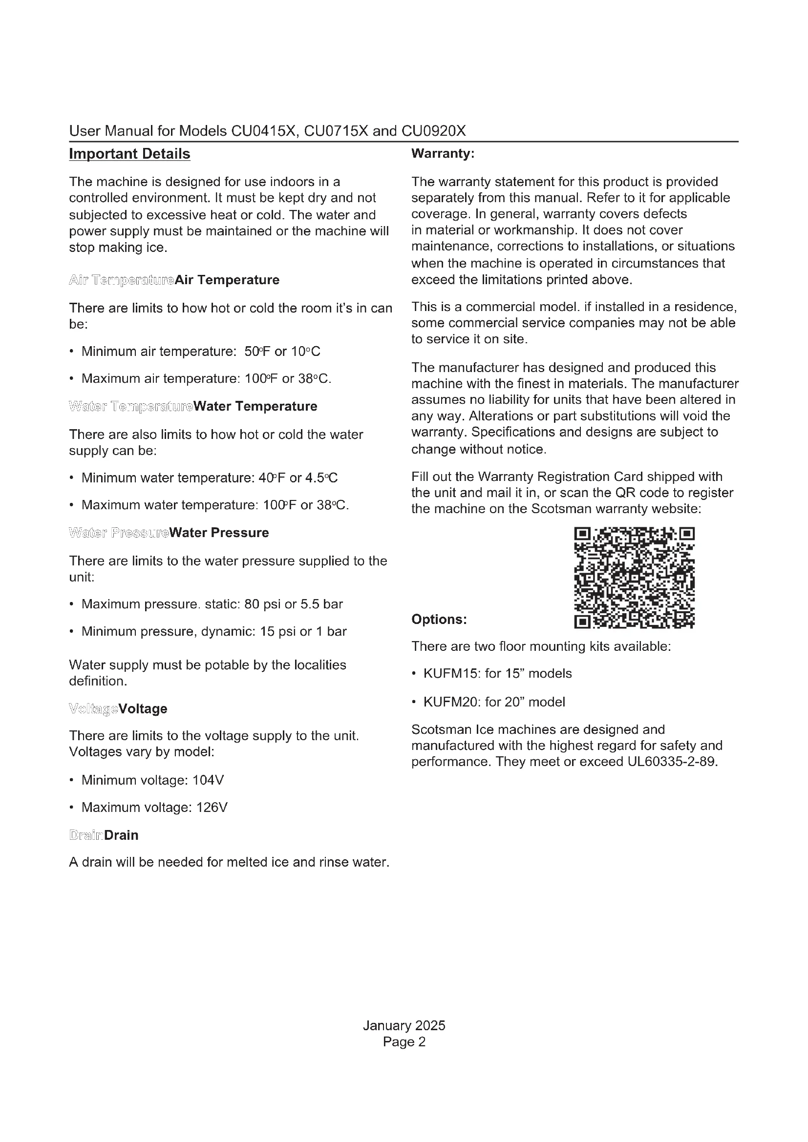
natural_image
Line drawing of a four-legged appliance with a curved top and side panel (no text or symbols)Safety Information
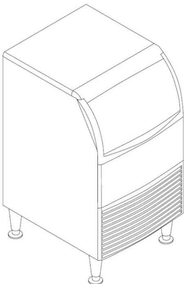
text_image
WARNING R290 Refrigerant is Flammable. Flame can cause burns or property damage Keep away from sources of fire
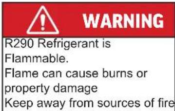
text_image
Warning sign depicting a flame symbol in yellow and black on white backgroundImportant Safety Information. Make sure to read through fully to avoid severe injury or death.

This ice machine contains FLAMMABLE refrigerant and improper use can result in fire or explosion. Do not use cigarettes, vapes, or cellphones near pipes or cables, as it can be a source of ignition or spark.

This ice machine must not be installed next to equipment with an open ignition source (ie. open flames, an operating gas appliance, or electric heater).

Do not store explosive substances such as aerosol cans with a flammable propellant in this appliance.

WARNING: In order to reduce flammability hazards the installation of this appliance must only be carried out by a suitably qualified person.

Do not install next to anything that continuously vibrates, avoiding excessive vibrations or pulsations.

Install in a well ventilated environment and ensure ventilation and outlets are not obstructed.

Properly secure electrical wiring and cabling for the machine to minimize wear and vibrations.

Keep fire extinguisher nearby in case of emergencies.

WARNING: Cancer and Reproductive Harm. Visit www.P65Warnings.ca.gov for details.

Use a Scotsman recommended technician certified to repair R290 equipment.

Install ONLY Scotsman factory service parts. Use of non-OEM parts can be dangerous due to the design changes needed to safely use R290 refrigerant.
Introduction
This manual provides essential information for installing, starting, and operating Scotsman ice makers and dispensers. Built on Scotsman's extensive experience in ice maker development and service, these machines deliver top-tier reliability. Follow the installation and maintenance instructions to maximize your machine's efficiency and lifespan.
Table of Contents
Important Details 2
Pre-Installation....3
Cabinet Layout, CU0415X and CU0715X 4
Cabinet Layout, CU0920X....5
Component Location 6
Connect the Power 7
Connect the Water Supply....8
Control Panel and Adjustments 9
Initial Start Up....10
Use and Operational Notes 11
Maintenance....12
Before Calling for Service....14
Decommissioning 15
Observe the Caution and Warning notices. They are indicators of important safety information. Keep this manual for future reference.
Important Details
The machine is designed for use indoors in a controlled environment. It must be kept dry and not subjected to excessive heat or cold. The water and power supply must be maintained or the machine will stop making ice.
Air Temperature Air Temperature
There are limits to how hot or cold the room it's in can be:
• Minimum air temperature: 50°F or 10°C
• Maximum air temperature: 100°F or 38°C.
Water Temperature Water Temperature
There are also limits to how hot or cold the water supply can be:
• Minimum water temperature: 40°F or 4.5°C
• Maximum water temperature: 100°F or 38°C.
Water Pressure Water Pressure
There are limits to the water pressure supplied to the unit:
• Maximum pressure. static: 80 psi or 5.5 bar
• Minimum pressure, dynamic: 15 psi or 1 bar
Water supply must be potable by the localities definition.
VoltageVoltage
There are limits to the voltage supply to the unit. Voltages vary by model:
• Minimum voltage: 104V
• Maximum voltage: 126V
Drain:Drain
A drain will be needed for melted ice and rinse water.
Warranty:
The warranty statement for this product is provided separately from this manual. Refer to it for applicable coverage. In general, warranty covers defects in material or workmanship. It does not cover maintenance, corrections to installations, or situations when the machine is operated in circumstances that exceed the limitations printed above.
This is a commercial model. if installed in a residence, some commercial service companies may not be able to service it on site.
The manufacturer has designed and produced this machine with the finest in materials. The manufacturer assumes no liability for units that have been altered in any way. Alterations or part substitutions will void the warranty. Specifications and designs are subject to change without notice.
Fill out the Warranty Registration Card shipped with the unit and mail it in, or scan the QR code to register the machine on the Scotsman warranty website:

text_image
QR code image containing encoded data, no visible human-readable textOptions:
There are two floor mounting kits available:
• KUFM15: for 15" models
- KUFM20: for 20" model
Scotsman Ice machines are designed and manufactured with the highest regard for safety and performance. They meet or exceed UL60335-2-89.
Pre-Installation
This appliance is intended to be used in commercial applications including:
- Restaurant kitchens
- Bars
- Hotels
Spacing:
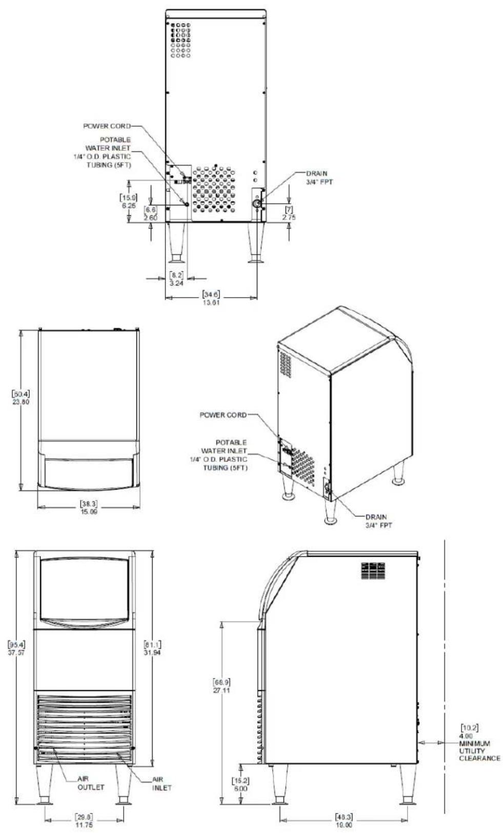
No additional spacing is required at the top or sides. However, suggested minimum side clearance for installation is 1/8" or 3 mm and suggested minimum top clearance is 1/4" or 7 mm.
Allow 4" (100 mm) minimum space at the back for the utility connections. Do not block louvers at the front of the cabinet.
Dimensions and Electrical:
| Model Electrical | (volts/Hz/Phase | Width(in / cm) | Depth(in/cm) | Height (w/o legs)(in/cm) | Total LoadAmps | Max FuseSize |
| CU0415MAX-1A 11 | 5/60/1 15 / 38 23.7 / 6 | 0.3 31.94 / 81.1 | 3.5 15A | |||
| CU0715MAX-1A 11 | 5/60/1 15 / 38 23.7 / 6 | 0.3 31.94 / 81.1 | 4.0 15A | |||
| CU0920MAX-1A 11 | 5/60/1 20 / 51 23.7 / 6 | 0.3 31.94 / 81.1 | 5.9 15A |
Location:
The unit can be built into a cabinet, as airflow circulates in and out the front vent. The front of the machine must not be blocked. Certain maintenance or repair procedures will require removal of the top, back and side panels, so plan ahead for service and maintenance needs.
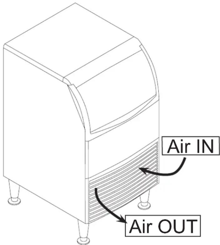
text_image
Air IN Air OUTUnpacking and Setup
Remove all shipping and packing materials that may be in the ice storage bin.
The unit can be installed with or without legs. The cabinet is equipped with small bumpers on the base to allow placement without legs. An optional floor mounting kit is also available to fill the gap between the machine and floor if not using legs.
If using legs, carefully tip the machine and install the legs by screwing them into the leg sockets in the bottom of the machine. For reference, the thread size is 5/8" – 11. If the machine has been tipped onto its side or back allow 1 hour before starting the unit for the oil in the refrigeration system to return to the compressor.
Place the machine in its intended location and level it front to back and left to right. If using legs, adjust their feet in and out to level the cabinet.
If legs are not used the bottom edges of the cabinet must be sealed to the floor.
If built into a cabinet, the adjacent cabinet walls will provide the means for containment. There are no means for attachment to the cabinet.
Be sure to remove the plastic covering the exterior panels. If left on, the plastic will be much harder to remove later.
Cabinet Layout, CU0415X and CU0715X
Cabinet Layout, CU0920X
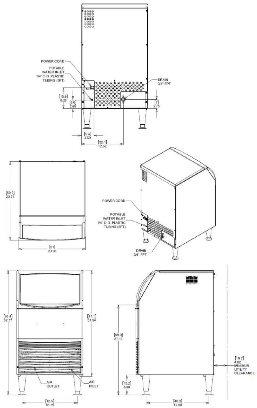
Component Location
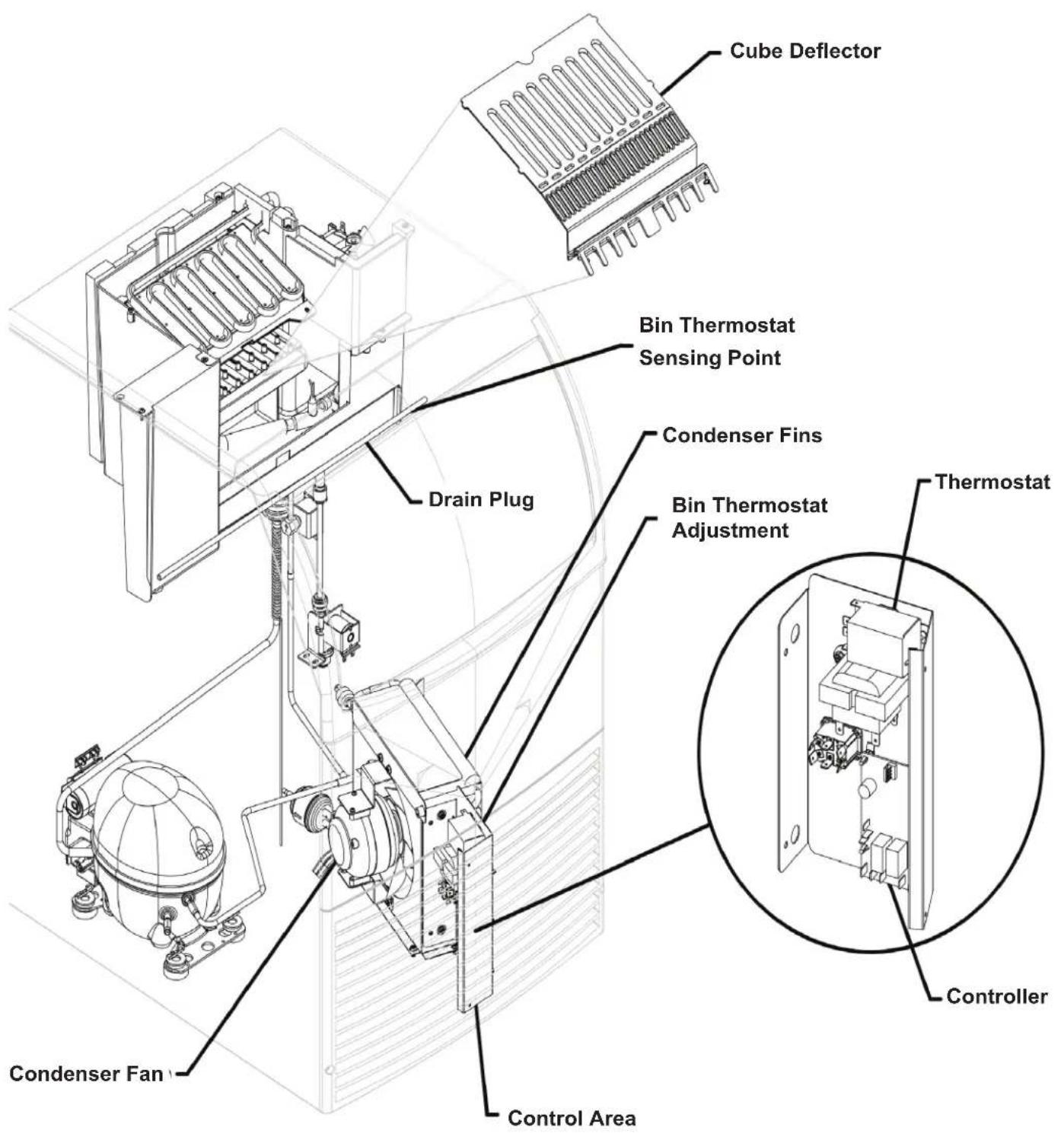
text_image
Cube Deflector Bin Thermostat Sensing Point Condenser Fins Drain Plug Bin Thermostat Adjustment Thermostat Controller Condenser Fan Control AreaConnect the Power
This is a cord-connected unit that must be connected to its own dedicated power supply. Check the dataplate on the back of the machine for required voltage, ampacity, and fuse size. Use only fuses or HACR-rated circuit breakers as specified.
Power Cord: Power Cord:
This machine is equipped with a cord and 5-15P plug. Please use the following guidelines when providing power to the machine:
- Make sure the machine is installed on a dedicated power supply. Using a shared circuit may cause malfunctions or damage.
- Never exceed the specified maximum fuse size.
- Follow all local codes, ensuring proper grounding, and do not use extension cords or attempt to bypass the ground prong on the electrical plug.
The use of a ground fault circuit interrupter (GFCI) or arc-fault circuit interrupter (ARCI) can lead to nuisance trips and is not recommended for use on most appliances including our equipment.
If local codes or other specifications require the use of ground fault circuit interrupters, a properly rated HACR GFCI or ARCI circuit breaker should be used. An outlet type GFCI or ARCI is not recommended for ice machines and other refrigeration equipment due to more frequent nuisance trips of the GFCI or ARCI.
Always check with your local electrical inspector about the specific code requirements in your area for GFCI or ARCI breakers and receptacles.
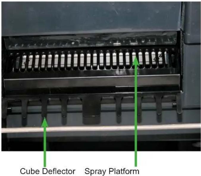
text_image
Cube Deflector Spray PlatformPush curtain back above the Spray Platform and check that it is in this position. The Cube Deflector must be positioned as shown. It snaps onto the front edge of the reservoir.
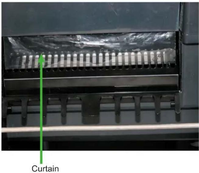
text_image
CurtainAfter checking spray platform, pull curtain down to hang freely. This is its normal position.
Connect the Water Supply
Plumbing information:
- The water supply connection is at the back panel. It is a 5' (1.5 meter) 1/4" (6.35 mm) OD plastic tube.
- A hand actuated valve within site of the machine is required to isolate the unit when it's being serviced.
- The machine has a built-in back flow preventer (an air gap between the end of the water inlet hose and the top of the reservoir water). No additional back flow preventer is needed.
• Water flow rate into machine is .25 GPM / .94 LPM.
For units that are built into a cabinet:
Include a loop or coil of tubing between the water supply and the connection on the ice machine. When the machine is pushed back into the cabinet, the tubing will coil and not kink.
Potable Water Inlet Tube
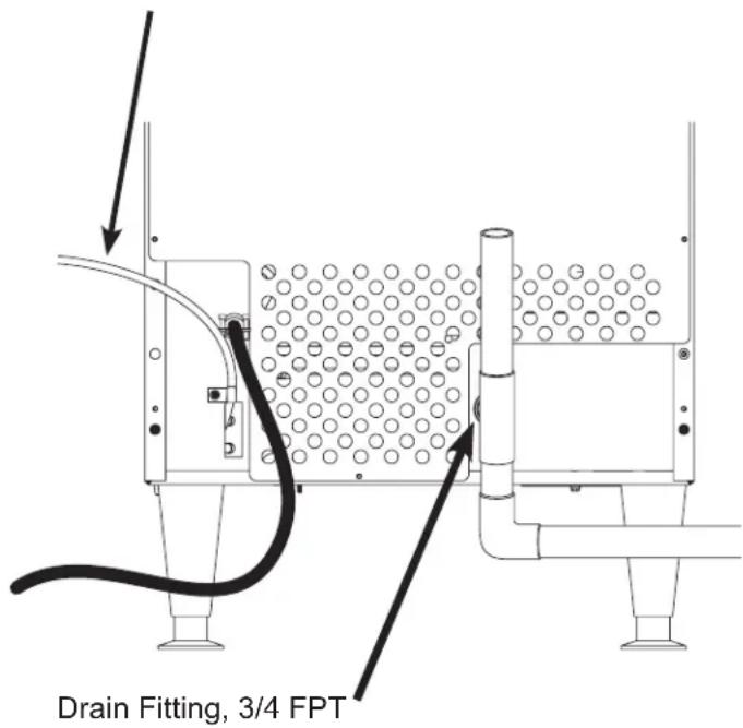
text_image
Drain Fitting, 3/4 FPTConnection Information: Connection Information:
WARNING: Connect to potable water supply only.
Note: Open the hand water valve to flush water through the connection point before connecting to the ice machine. ice machine.
-
Cut cable ties securing hose and power cord to unit.
-
Connect to cold, potable water using the necessary adapters for the 1/4" OD plastic tube.
- If using compression fittings they require a ferrule or sleeve and insert.
- A female 3/8" compression adapter x 1/4" OD compression allows connection to a typical 3/8" OD compression angle valve.
- Another connection method is by quick connect fittings.
Note: Do not use a piercing-type saddle valve to connect to the building's water supply. Valves of that type restrict water flow and clog easily.
Connect the Drain
The drain connection is at the back panel. The fitting size is 3/4" FPT.
- Connect rigid tubing to this fitting and vent it at the machine, use an 8" or 200 mm vertical tube for the vent.
- Slope drain tubing down from the ice machine to the building drain and the slope must be at least 1/4" per foot or 20 mm per meter.
- Insulate the drain tubing to reduce condensation and is recommended for environments that have high humidity.
Due to the potential for leaks, condensate pumps are not recommended.
Installation Check List
- Has the machine been installed indoors in an environment suitable for it?
- Have all of the shipping items and packaging been removed?
- Has the plastic covering the exterior panels been removed?
- Is the cube deflector in the correct position?
- Is the clear plastic curtain hanging down and free to move?
- Has the water supply been connected and confirmed to not leak?
- Has a properly sized and sloped drain tube been attached?
- Has the correct voltage power supply been connected?
Control Panel and Adjustments
Adjustment Indicator Lights
Each push and release of the + or - button will change the five lights that glow or blink indicating a change in ice size or harvest time.
Pushing + one time changes a blinking light to steady on type. If the lights are on steady a single push of + will add one more light to the right and it will blink. There are 10 settings. All 5 lights on steady is the maximum setting and one blinking light is the minimum.
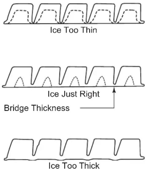
Ice Bridge Thickness Adjustment
Refer to the Ice Thickness Diagram for proper ice size.
Adjust by pushing the + sign or – sign on the ice bridge adjustment section of the control panel. Changing bridge thickness should be a one-time adjustment as the machine will automatically maintain that ice thickness.
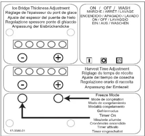
text_image
Ice Bridge Thickness Adjustment Réglage de l'épaisseur du pont de glace Ajuste del espesor del puente de hielo Regolazione spessore ponte di ghiaccio Anpassung der Eisbrückendicke ON / OFF / WASH MARCHE / ARRET / LAVAGE ENCENDIDO / APAGADO / LAVADO ON / OFF / LAVAGGIO EIN / AUS / WASCHEN Harvest Time Adjustment Réglage du temps de récolte Ajuste del tiempo de cosecha Regolazione orario di raccolta Anpassung der Emtezeit Freeze Mode Mode de congelation Modo de congelamiento Modalità congelamento Gefriermodus Timer On Minuterie allumée Cronômetro encendido Timer attivato Timer eingeschaltet 17-3386-01Freeze Mode and Timer Light
The freeze mode light is on when unit is in a freeze cycle.
The timer on light is on when the trigger point temperature is reached in freeze or harvest cycles.
Ice Thickness Diagram
text_image
Ice Too Thin Ice Just Right Bridge Thickness Ice Too ThickHarvest Cycle Time Adjustment
After ice has formed in the inverted mold, it must be released through a harvest cycle so it can be deposited in the storage bin section. The harvest cycle must be long enough for the ice to release. While the harvest cycle length is self adjusting, it can also be manually adjusted if needed.
The proper length of the harvest cycle is long enough for the ice to fall into the bin, with about 10 seconds extra harvest time (pump and fan are off) before the freeze cycle restarts.
If the harvest time is too short to release the ice, the time may be increased by pushing the + sign on the harvest time adjustment section of the control panel. Operate the machine for another cycle to confirm that the adjustment was correct. Note that too much harvest time will slightly decrease ice making capacity.
| Model Freeze | Setting Harvest Setting | |||||
| NUMBER | TEMP. L | GHTS NU | MBER TEM | MP. LIGHTS | ||
| CU0415MAX-1A 4 | 10.0°F 7 49 | 8°F | ● ● | ● ● ● ◎ | ||
| CU0715MAX-1A 5 | 6.7°F 7 49.8 | °F | ● ● ◎ | ● ● ● ◎ | ||
| CU0920MAX-1A 7 | 0.0°F 7 49.8 | °F | ● ● ● ◎ | ● ● ● ◎ | ||
Initial Start Up
- Remove the front panel by removing the two screws holding it to the cabinet and pulling the panel down and off the machine.
- Turn on the water supply, correct any leaks.
Note: Water supply MUST be turned on first to allow water to enter the machine properly.
- Locate the ON/OFF/WASH master switch.
- Move the switch to the ON position.
- Ice bridge thickness and harvest time indicator lights will switch on. They will not change unless the cube size or harvest times are manually adjusted. The timer light will also be on.
- The unit begins to fill the reservoir with water. Two streams of water can be seen behind the curtain. The compressor and hot gas valve will be energized, but the fan motor and pump will be off.
After several minutes, the water will have filled the reservoir but will continue to fill and excess water will drain from the machine. This is normal and helps the machine from forming excessive mineral scale.
- After 2 minutes the water and hot gas valves will close and the pump and fan motors will start. A blue light in the control panel will glow indicating the beginning of the freeze cycle.
- Warm air will begin to blow out the left front of the machine and water will spray up at the inverted ice making mold. It is normal for a small amount of water to drip from the ice making area.
When the water temperature reaches a pre-set point, the water pump will stop for about 30 seconds then resume.
Freezing then continues for many minutes until the temperature of the refrigeration system drops to a set point, indicated by a yellow light glowing on the control panel. In colder rooms the fan motor may turn on and off. After the yellow light switches on, the freeze cycle continues for seven more minutes. At that time the unit changes to the ice release or harvest cycle. During the ice harvest, the hot gas valve and inlet water valve are open, while the pump and fan motors will stop.
The blue and yellow lights will go out. Water will refill the reservoir.
- Within a minute or so, the ice formed in the mold will fall down and slide into the ice storage bin. All of the ice formed will fall at once and the next freeze cycle will begin a few seconds later. The timer light may switch on at the end of the harvest cycle.
- Check the thickness of the ice connecting the cubes to each other, that connection is known as a bridge and it should be about 1/8" or 3 to 4 mm thick. It is preset from the factory and should be satisfactory.
Adjustments:
If the ice bridge is too big or too small, the thickness may be adjusted.
Note: The bridge thickness adjustment is used to obtain the CORRECT size, not to adjust to individual preferences. Do NOT make the ice bridge too thick or too thin, as either will reduce ice making capacity. Do NOT attempt to adjust the machine to release individual cubes. There is only ONE correct size.
- Ice making will continue until the ice level reaches the metal tube in the storage bin. When ice contacts that tube, the machine will stop making ice. This can occur in any part of any cycle.
- Removing ice from the ice storage bin will restart the ice making process.
- Check for and correct any water leaks from the unit or drain system.
- Return the front panel to its normal position and secure it to the cabinet with the original screws.
Typical Cycle Times (minutes)
Note: First cycle after any restart will be longer than listed here.
| 70/50°F. (21/10°C.) 90 | 70 °F. (32/21°C.) | |
| CU0415X 2 | 8-30 34-37 | |
| CU0715X 1 | 6-18 23-26 | |
| CU0920X 1 | 4-16 17-19 |
The time to fill a warm storage bin from empty varies by cabinet temperature and cycle time, but will take about 10-12 hours.
Use and Operational Notes
To use, simply lift the door by its bottom edge and slide it up and into the top of the machine. Use the scoop to remove ice, then close the door when finished.
The machine will make the most ice if it has plenty of room to breathe. This is an air cooled product and it must be able to take in room temperature air and discharge air heated by the ice making process. Blockage of vents or exposure to excessive heat will reduce the ice making and storage capacity of the machine. The storage bin is insulated but not refrigerated, so ice will melt during use. That is normal and assures that fresh ice is available in the bin.
The fan will make some noise during operation. However, rattles and other vibrations are not normal and should be attended to. When the air temperature surrounding the machine is cold, the fan might cycle on and off during the freeze mode.
If the machine is in a space colder than the minimums listed, it will not switch on to make ice.
Minor adjustments may be made to compensate for local conditions by rotating the adjustment screw which is visible above the control area. If in a cold room, CW rotation changes the control to COLDER to fill the bin higher.
If installed at an altitude greater than 2000 ft or 610 meters above sea level, the bin thermostat may need internal adjustment. The adjustment screw is behind the front of the control, accessed through a hole for it.
Bin Thermostat Altitude Adjustment Table:
| Altitude (ft) Altitude (meters) Degree of adjustment | |
| 2000 600 31 CW | |
| 3000 900 52 CW | |
| 4000 1200 72 CW | |
| 5000 1500 92 CW | |
| 6000 1800 111 CW | |
| 7000 2100 128 CW | |
| ▲CAUTION | No StepDo not stand on the machine.Severe damage can occur. |
This appliance is not intended for use by persons (including children) with reduced physical, sensory or mental capabilities, or lack of experience and knowledge, unless they have been given supervision or instruction concerning use of the appliance by a person responsible for their safety.
Children should be supervised to ensure that they do not play with the appliance.
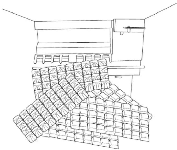
natural_image
Line drawing of a mechanical device with stacked blocks, no text or symbols presentTypical Full Bin
Maintenance
Regularly vacuum the right side of the air cooled condenser with a brush to remove all loose dust and dirt. Be careful not to damage the fins.
Cubed ice machines of this type make ice that is more pure than the water supplied to it. Since the ice has fewer impurities, the water that remains in the reservoir has more. The water system dilutes that concentration, but eventually it does build up and needs to be removed. This process is called scale removal and should be performed at least every 6 months.
Scale Removal Process
Materials needed:
- Food grade, nickel safe scale remover for ice machines, also known as ice machine cleaner.
- Sanitizer
- Hand tools.
- Clean bucket
- Clean cloths
-
Rubber or plastic gloves
-
Remove front panel.
-
Move master switch to OFF, wait a minute and then move it to ON.
-
When the freeze cycle begins (blue light on), switch the machine to OFF.
-
Remove and discard the ice.
-
Drain reservoir by pulling drain plug and then return drain plug to its original position.
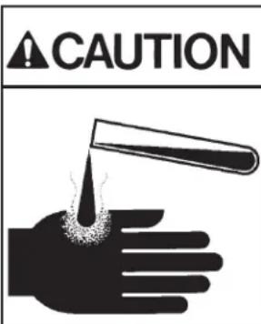
text_image
CAUTIONIce machine scale remover contains acids. Acids can cause burns.
If concentrated cleaner comes in contact with skin, flush with water. If swallowed, do NOT induce vomiting. Give large amounts of water or milk. Call Physician immediately. Keep out of the reach of children.
- Mix a solution of 5 oz or 150 ml of Scotsman Clear 1 Scale Remover and 2.5 quarts or 2.4 liters of clean, warm (95°F/35°C to 115°F./46°C) water.
- Pour the solution into the reservoir by carefully adding it at the reservoir's front lip.
- Move the master switch to the WASH position.
- Wait 10 minutes.
- Move the master switch to the OFF position.
- Drain the reservoir by removing drain plug and draining the solution into the bin. Return the drain plug to its normal position.
- Remove spray platform by removing cube chute and lifting spray platform up and off its connection. If needed, open platform and confirm all jets are open. Rinse out any debris, reclose and return it and the cube chute to the unit. Be sure gasket is positioned correctly - narrow side faces up toward jets.
- Pour 2.5 quarts or 2.4 liters of warm (95°F/35°C to 115°F./46°C) water into the reservoir by adding it at the reservoirs' front lip.
- Switch the master switch to WASH for 1 minute, then switch it to OFF.
- Repeat step 11. Go to the next process to sanitize the machine.
Sanitization Process
-
Create a solution of sanitizer by missing 1 gallon (4 liters) of clean, warm potable water ( 105^ – 115^ F) with 1.6 oz of locally approved sanitizer.
-
Pour about half of the sanitizer mix into the reservoir.
-
Remove the cube chute and spray platforms and wash them with the sanitizer, then return them to the ice machine.
-
Move the master switch to the WASH position.
-
Circulate the sanitizer for 2 minutes.
-
Move the master switch to OFF.
-
Drain the reservoir into the storage bin by removing the drain plug. Return the drain plug to its normal position.
-
Wipe down all interior surfaces of the ice machine storage bin, reservoir surface and inside of the door with the remaining sanitizer solution.
- Pour any excess sanitizer down the ice machine bin drain.
- Pour 2.5 quarts or 2.4 liters of warm (95°F/35°C to 115°F./46°C) water into the reservoir by adding it at the reservoirs' front lip.
- Move the master switch to the Wash position for 1 minute, then switch it to OFF.
- Drain the reservoir by removing the drain plug and draining the solution into the bin. Return the drain plug to its normal position.
- Move switch to the ON position. The machine will resume normal ice making.
- Return the front panel to its original position and secure it with the original screws.
Cleaning the Condenser
- Remove the front panel.
- Switch the machine to OFF.
- Vacuum the surface of the condenser fins, carefully brush off any loose dirt. If grease is embedded, use coil cleaner to wash it out.
- Switch the machine to ICE.
- Return the front panel to its original position.
Before Calling for Service
No ice – Check water supply
No ice – Check power supply. Remove front panel, if there are no lights on the control panel either the bin thermostat is open, keeping the machine off, OR there is no power to the controller.
No ice – Check temperature of cabinet. If too cold, the machine will not operate.
Slow production – Check condenser for dirt, clean condenser.
Slow production – Check temperature of cabinet, if the room is hot or air flow restricted, production will be slow.
Ice is poorly formed. Check spray. If some spray jets are restricted, ice will be poorly formed. Clean water system to correct.
Note: In areas where the water supply has a high mineral content, the spray jets may need frequent clearing. Increasing the harvest time will flush more water and help to reduce the frequency of cleaning.
To increase harvest time:
-
Confirm unit is in ice making mode. If the bin is full and the unit is off the controller cannot be adjusted.
-
Remove the front louvered panel.
-
Increase the time by pushing the + sign on the harvest time adjustment section of the control panel. Each push increases the time.
-
Return the front louvered panel to its normal position.
Decommissioning
Only qualified technicians familiar with R290 refrigerant should decommission a machine, as special tools and containers are required for the removal, transportation, and disposal of this highly flammable substance.
• Before attempting the procedure:
* Ensure that all protective gear is present and used throughout the procedure.
* Make sure recovery equipment and containers are available and ready for use. All containers used for recovery must be rated for R290 refrigerant and must be labeled as such.
* Weigh any refrigerant prior to reclaiming.
- Maintain safety through standard operating procedures as outlined on page 20 of this document. Be sure to follow local, state, and federal guidelines for proper disposal.
- Do not fill containers more than 80% and do not exceed the pressure limits of the container. Make sure the machine to be decommissioned is in satisfactory working order and that the electrical components of the machine are properly sealed to prevent ignition.
- Recovered refrigerant should not be charged into another refrigerating system or mixed in another container.
- Make sure to safely transport the refrigerant in line with standard operating procedures.
- All recovered refrigerant must be returned to refrigerant supplier for proper disposal.
- If compressor or compressor oils are removed ensure it has been removed to an acceptable level so the flammable refrigerant does not remain in the lubricant.
Scotsman®
Ice Systems
natural_image
Line drawing of a four-legged appliance with slatted front panel and side legs (no text or symbols)
WARNING
text_image
Warning sign depicting a flame symbol in yellow and black, indicating hazard or electrical hazard.natural_image
Close-up of a black metal ventilation grille with green arrows indicating upward motion (no text or symbols)natural_image
Close-up of a mechanical component with a green arrow pointing to a textured surface (no visible text or symbols)Rideau
natural_image
Technical diagram of a mechanical or fluidic device with pipes and a central container, no visible text or symbolsManchon de raccordement du drain, 3/4 FPT
natural_image
Illustration of a hand holding a test tube with liquid being poured into the palm (no text or symbols)natural_image
Line drawing of a four-legged appliance with slatted front panel and side legs (no text or symbols)
WARNING
text_image
Warning sign depicting a flame symbol in yellow and black on white backgroundnatural_image
Close-up of a black metal grate with parallel slots and green arrows pointing upward (no text or symbols)natural_image
Silhouette of a hand holding a test tube with a droplet falling from the tip (no text or symbols)101 Corporate Woods Parkway
Vernon Hills, IL 60061
USA
800-726-8762
www.scotsman-ice.com