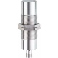
UIT302 - Ultrasonic cleaner IFM - Free user manual and instructions
Find the device manual for free UIT302 IFM in PDF.


User questions about UIT302 IFM
0 question about this device. Answer the ones you know or ask your own.
Ask a new question about this device
Download the instructions for your Ultrasonic cleaner in PDF format for free! Find your manual UIT302 - IFM and take your electronic device back in hand. On this page are published all the documents necessary for the use of your device. UIT302 by IFM.
USER MANUAL UIT302 IFM
Info card
Ultrasonic sensors

1 Intended use

This info card is to complement the data sheets.
Further information and contact addresses at www.ifm.com.
Proximity switches are used for the non-contact detection of positions, levels and point levels in industrial applications. The application must remain within the limits specified in the technical data sheet.
While in use the products are exposed to influences which may have an effect on function, life, quality and reliability of the product. Environmental influences exceeding the limits specified in the technical data sheet may impair the function of the device. This applies in particular to applications in hazardous areas and with adverse environmental influence such as pressure, chemicals, temperature fluctuations, moisture and radiation as well as mechanical stress, especially if the products are not installed properly.
It is the customer's responsibility to ensure that the products are suitable for the intended application. Using the products in applications where the safety of people depends on the function of the product is not permitted. If these instructions are not adhered to, death or severe injury may occur.
Unless otherwise specified in the data sheet, the products are designed for operation at altitudes up to 2,000 m above sea level.

Products with protection class II must be regularly checked for damage.
▶ In case of damage, disconnect the device from the power supply and replace it.
For USA and Canada: This product is specified for the direct control of a production process in a dedicated building or factory (industrial area).
1.1 Cybersecurity
Installation
The device is suitable for operation in a secure environment according to IEC 62443-1-1.
The device was designed for operation behind a firewall.
- Carry out a risk assessment of the system according to IEC 62443-1-1.
▶ Take measures to ensure physical security.
Operation
▶ Observe the security functions described in the product documentation and the recommendations for their use.
Maintenance
- Back up system configuration and system data in accordance with your company's change management processes.
Decommissioning
▶ Ensure that no sensitive information can fall into unauthorised hands.
▶ Always reset the system settings to the factory settings before decommissioning the device.
2 Function

UGT / UIT function
1: Connection
2: Housing
3: Electronics
4: Transducer
5: Sound waves
6: Object / reflector
UGR function
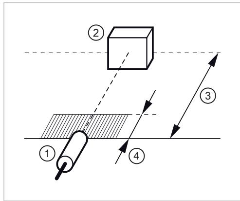
1: Device
2: Target (object to be detected)
3: Operating distance
4: Blind zone
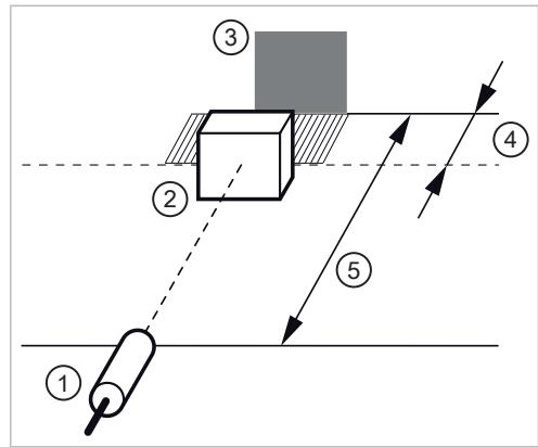
1: Device
2: Target (object to be detected)
3: Reflector
4: Minimum distance object / reflector
5: Operating distance
2.1 Lateral approach / Switching zone
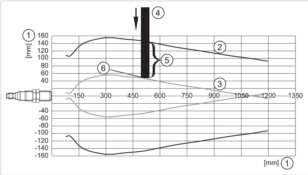
1: Distance
2: Sensing range (if 50 % of the target area is within the detection range, distances can be determined)
3: Switch-on curve (describes the switch-on point when the edge of the target approaches laterally)
4: Target 200 x 200 mm (depending on the range)
5: 50 % of the target in the sensing range
6 : Switch point
2.2 Operating distance
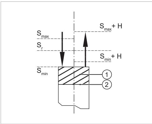
Real operating distance Sr
smax : Largest operating distance
sr : Real operating distance
smin : Smallest operating distance
1: Blind zone
2: Sensing face
ating distance Sr is between the minimum and max-ble operating distances Smin and Smax: Smin ≤ Sr
Hysteresis H
The hysteresis H is specified as a percentage of the real operating distance. It is measured at the rated supply voltage at an ambient temperature of (23 ± 5) °C and must be less than 20 % of the real operating distance: H ≤ 0.2 × Sr .
3 Installation
3.1 Minimum distances when installing devices on opposite sides

| Version | Range in mm | Distance X in mm |
| M18 standard | 1,600 | 5,000 |
| 2,200 | 6,600 | |
| M18 short / M18 Cube | 300 | 2,200 |
| 800 | 3,000 | |
| 1,200 | 3,800 | |
| M18 full metal | 400 | 2,000 |
| 1,000 | 4,500 | |
| M30 standard | 3,500 | 10,500 |
| 6,000 | 18,000 | |
| 8,000 | 24,000 | |
| M30 full metal | 2,500 | 8,500 |
3.2 Side-by-side installation

| Version | Range in mm | Distance X in mm |
| M18 standard | 1,600 | 720 |
| 2,200 | 840 | |
| M18 short / M18 Cube | 300 | 260 |
| 800 | 280 | |
| 1,200 | 550 | |
| M18 full metal | 400 | 250 |
| 1,000 | 500 | |
| M30 standard | 3,500 | 1,400 |
| 6,000 | 1,600 | |
| 8,000 | 2,150 | |
| M30 full metal | 2,500 | 1,500 |
4 Electrical connection

The device must be connected by a qualified electrician.
▶ Observe the national and international regulations for the installation of electrical equipment.
▶ Geräte mit Schutzklasse III ausschließlich nach SELV / PELV mit Spannung versorgen.
▶ Disconnect power.
▶ Gerät nach Angaben auf dem Datenblatt/Typenschild anschließen.
4.1 Connection systems

Sensors must not be operated in parallel connection (OR)!
Series connection (AND) is not recommended since the power-on delay times, voltage drops and current consumption add up. UB\ min (sensor) and UHIGH\ min (load) must remain unchanged.
5 Glossary
| Term | Explanation |
| Active zone | Area in which the device reacts to the approach of the target. |
| Term | Explanation |
| Output function | Normally open: Object within the active zone > output switched. Normally closed: Object within the active zone > output blocked. Programmable: Choice between normally closed and normally open. Positive switching: positive output signal (to L-). Negative switching: negative output signal (to L+). |
| Switch-off delay | Time delay between the target leaving the active zone of the device and the switching of the output stage, determined using a mechanical measurement method. |
| Rated frequency of the supply network | 50 Hz, 60 Hz or direct voltage |
| Rated insulation voltage | AC and DC devices with protection class II: 250 V ACDC devices with protection class III: 60 V DC |
| Rated short-circuit current | For short-circuit-proof devices: 100 A. For AC devices without short-circuit protection: Required fuse ➕ Data sheet. |
| Rated impulse withstand voltage | AC devices depending on UB: 140 V AC = 2.5 kV or 250 V AC = 4 kV( ≈ overvoltage category III). DC devices with protection class II: 4 kV ( ≈ overvoltage category III). DC devices with protection class III: 60 V DC: 0.8 kV ( ≈ overvoltage category II). |
| Power-on delay time | The time the device needs to be ready for operation after application of the operating voltage. |
| Operating voltage► Start-up behaviour | Voltage range in which the device operates reliably. A stabilised and smoothed direct voltage should be used. Once the operating voltage has reached its minimum value for the first time, the final operating voltage should be reached within one second at the latest. Start-up should be continuous and monotonic. |
| Blind zone | Zone between the sensing face and the minimum distance within which objects cannot be detected. |
| Switch-on delay | Time delay between the target entering the active zone of the device and the switching of the output stage, determined using a mechanical measurement method. |
| Recommended direction of approach | The objects to be detected should move laterally into the active zone. The distance between the sensing face and the object should be approximately equal to half the operating distance. |
| Utilisation category | AC devices: AC-140 (control of small electromagnetic loads with holding currents < 200 mA). DC devices: DC-13 (control of solenoids). |
| Hysteresis | Difference between switch-on and switch-off point. |
| Short-circuit protection | Pulsed short-circuit for short-circuit-proof devices. If applicable, observe the fuse specifications given in the datasheet. In devices with pulsed short-circuit, the short-circuit protection may activate in the case of incandescent lamps, electronic relays, capacitive loads or low-resistance loads. |
| No-load current | Current consumption without load current for the internal supply of 3-wire devices. |
| Measuring range | Distance range in which the process value changes. The final value of the measuring range is the maximum value that the measured value can reach. |
| Minimum operating current Minimum load current | Smallest operating current required for maintaining conductivity of the switching element in 2-wire devices. |
| Product standard | Proximity switches: IEC 60947-5-2 |
| Leakage current | Current for the internal supply of 2-wire devices, also flows through the load when the output is blocked. |
| Switch point drift | Change in the operating distance as a function of the ambient temperature specified in the data sheet. |
| Protection rating | IPxy according to IEC 60529IP68 test condition: 1 m water depth for 7 daysIPx9K according to ISO 20653 |
| Voltage drop | Voltage at the output switching element in the conductive state. |
| Standard target | Object with standardised dimensions and materials that causes a change in the switching state when moved into the active zone. |
| Transport and storage temperature Ambient temperature | The transport and storage temperature corresponds to the ambient temperature specified in the data sheet.► With cable devices, do not move the cable below -25 °C. |
| Ultrasonic reflector for UGR version | The functional specifications refer to a mild steel reflector defined by ifm at maximum range with an edge length of 200 mm (UGT) or 400 mm (UIT). Besides mild steel reflectors, objects that can reflect sound well can also be used as a reflector. The min. reflector size depends on the object size and the angle of aperture of the emitted sound. |
| Pollution degree | The products are designed for pollution degree 3 according to IEC 60947-1. |
| Maintenance, repair and disposal | When used correctly and in accordance with the intended use, no further maintenance and repair measures are necessary. ➕ 1► After use dispose of the device in an environmentally friendly way in accordance with the applicable national regulations. |
| Repeatability | Unless otherwise specified in the data sheet, the difference between any two measurements within the measuring range must not exceed 10 %. |
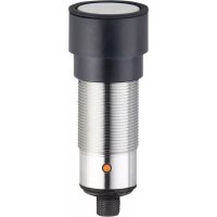
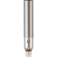
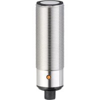
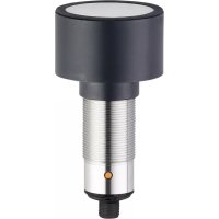
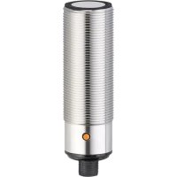
Brand : IFM
Model : UIT302
Category : Ultrasonic cleaner