
XAVAX8100 - Cd player/recorder SONY - Free user manual and instructions
Find the device manual for free XAVAX8100 SONY in PDF.
| Product Type | CD player/recorder for vehicle |
| Brand | Sony |
| Model | XAVAX8100 |
| Mounting Dimensions | 182 mm × 53 mm × 160 mm |
| Weight | 2.4 kg |
| Power Supply | Vehicle battery 12 V DC (negative ground) |
| Rated Current Consumption | 10 A |
| Screen Type | Color LCD monitor, 8.95 inches (227 mm), active matrix TFT |
| Screen Resolution | 800 × 3 (RGB) × 480 pixels (1,152,000 pixels) |
| FM Radio Receiver | Range 87.5 - 107.9 MHz, usable sensitivity 7 dBf |
| AM Radio Receiver | Range 530 - 1,710 kHz, sensitivity 32 μV |
| USB Player | High-speed USB port, max current 1.5 A |
| HDMI Input | Yes (480p, 576p, 720p) |
| Bluetooth | Version not specified, range ~10 m, profiles A2DP, HFP, codecs SBC, AAC |
| Maximum Output Power | 55 W × 4 (at 4 Ω) |
| Speaker Impedance | 4 Ω to 8 Ω |
| Main Features | Apple CarPlay, Android Auto, WebLink, SiriusXM Ready, rear view camera, wired remote control, voice commands |
| Care and Cleaning | Clean LCD screen with a soft, dry cloth. Do not use solvents. |
| Safety | Video lock function when vehicle is moving. Parking brake required to display video. |
| Replacement Parts & Repairability | Replaceable 10 A fuse. Consult a Sony retailer for repairs. |
| General Information | Operating temperature: 0 °C to 40 °C. Remote control battery: CR2025. |
Frequently Asked Questions - XAVAX8100 SONY
User questions about XAVAX8100 SONY
0 question about this device. Answer the ones you know or ask your own.
Ask a new question about this device
Download the instructions for your Cd player/recorder in PDF format for free! Find your manual XAVAX8100 - SONY and take your electronic device back in hand. On this page are published all the documents necessary for the use of your device. XAVAX8100 by SONY.
USER MANUAL XAVAX8100 SONY
Operating Instructions
GB
Mode d'emploi
FR
The model and serial numbers are located on the bottom of the unit.
Record the serial number in the space provided below.
Refer to these numbers whenever you call upon your Sony dealer regarding this product.
Model No. XAV-AX8100
Serial No. ____
To cancel the demonstration (Demo) display, see page 7.

XAV-AX8100(UC)
https://rd1.sony.net/help/ev/xav-ax81/h_zz/
Warning
For safety, be sure to install this unit in the dashboard of the car as the rear side of the unit becomes hot during use.
For details, see "Connection/Installation" (page 11).
The nameplate indicating operating voltage, etc., is located on the bottom of the chassis.
The validity of the CE marking is restricted to only those countries where it is legally enforced, mainly in the countries EEA (European Economic Area) and Switzerland.
WARNING
To prevent fire or shock hazard, do not expose the unit to rain or moisture.
To avoid electrical shock, do not open the cabinet. Refer servicing to qualified personnel only.
FOR THE CUSTOMERS IN THE USA. NOT APPLICABLE IN CANADA, INCLUDING IN THE PROVINCE OF QUEBEC.
POUR LES CLIENTS AUX ÉTATS-UNIS. NON APPLICABLE AU CANADA, Y COMPRIS LA PROVINCE DE QUÉBEC.
This equipment has been tested and found to comply with the limits for a Class B digital device, pursuant to Part 15 of the FCC Rules. These limits are designed to provide reasonable protection against harmful interference in a residential installation. This equipment generates, uses, and can radiate radio frequency energy and, if not installed and used in accordance with the instructions, may cause harmful interference to radio communications. However, there is no guarantee that interference will not occur in a particular installation. If this equipment does cause harmful interference to radio or television reception, which can be determined by turning the equipment off and on, the user is encouraged to try to correct the interference by one or more of the following measures:
- Reorient or relocate the receiving antenna.
- Increase the separation between the equipment and receiver.
- Connect the equipment into an outlet on a circuit different from that to which the receiver is connected.
- Consult the dealer or an experienced radio/TV technician for help.
You are cautioned that any changes or modifications not expressly approved in this manual could void your authority to operate this equipment.
This device complies with part 15 of FCC Rules and Innovation, Science and Economic Development Canada's licence-exempt RSS(s). Operation is subject to the following two conditions:
(1) this device may not cause harmful interference, and
(2) this device must accept any interference received, including interference that may cause undesired operation.
This transmitter must not be co-located or operated in conjunction with any other antenna or transmitter.
This equipment complies with FCC/ISED radiation exposure limits set forth for an uncontrolled environment and meets the FCC radio frequency (RF) Exposure Guidelines and RSS-102 of the ISED radio frequency (RF) Exposure rules as this equipment has very low levels of RF energy.
If you have any questions about this product:
Visit: https://www.sony.com/electronics/support Contact: Sony Customer Information Service Center at 1-800-222-7669
Write: Sony Customer Information Service Center 12451 Gateway Blvd., Fort Myers, FL 33913
Supplier's Declaration of Conformity Trade Name: SONY
Model: XAV-AX8100
Responsible Party: Sony Electronics Inc.
Address: 16535 Via Esprillo, San Diego, CA 92127 U.S.A.
Telephone Number: 858-942-2230
This device complies with part 15 of the FCC rules. Operation is subject to the following two conditions:
(1) This device may not cause harmful interference, and
(2) this device must accept any interference received, including interference that may cause undesired operation.
For the State of California, USA only
Perchlorate Material – special handling may apply, See
www.dtsc.ca.gov/hazardouswaste/perchlorate

WARNING: Do not ingest battery, Chemical Burn Hazard.
The remote commander contains a coin/ button cell battery. If the coin/button cell battery is swallowed, it can cause severe internal burns in just 2 hours and can lead to death.
Keep new and used batteries away from children. If the battery compartment does not close securely, stop using the product and keep it away from children.
If you think batteries might have been swallowed or placed inside any part of the body, seek immediate medical attention.
Note on the lithium battery
Do not expose the battery to excessive heat such as direct sunlight, fire or the like.
Warning if your car's ignition has no ACC position
Do not install this unit in a car that has no ACC position. The display of the unit does not turn off even after turning the ignition off, and this causes battery drain.
Disclaimer regarding services offered by third parties
Services offered by third parties may be changed, suspended, or terminated without prior notice.
Sony does not bear any responsibility in these sorts of situations.
Important notice
Caution
IN NO EVENT SHALL SONY BE LIABLE FOR ANY INCIDENTAL, INDIRECT OR CONSEQUENTIAL DAMAGES OR OTHER DAMAGES INCLUDING, WITHOUT LIMITATION, LOSS OF PROFITS, LOSS OF REVENUE, LOSS OF DATA, LOSS OF USE OF THE PRODUCT OR ANY ASSOCIATED EQUIPMENT, DOWNTIME, AND PURCHASER'S TIME RELATED TO OR ARISING OUT OF THE USE OF THIS PRODUCT, ITS HARDWARE AND/OR ITS SOFTWARE.
Dear customer, this product includes a radio transmitter.
Please check your vehicle operation manual or contact the manufacturer of your vehicle or your vehicle dealer, before you install this product into your vehicle.
Emergency calls
This BLUETOOTH car handsfree and the electronic device connected to the handsfree operate using radio signals, cellular, and landline networks as well as user-programmed function, which cannot guarantee connection under all conditions.
Therefore do not rely solely upon any electronic device for essential communications (such as medical emergencies).
On BLUETOOTH communication
- Microwaves emitting from a BLUETOOTH device may affect the operation of electronic medical devices. Turn off this unit and other BLUETOOTH devices in the following locations, as it may cause an accident.
- where inflammable gas is present, in a hospital, train, airplane, or petrol station
- near automatic doors or a fire alarm
- This unit supports security capabilities that comply with the BLUETOOTH standard to provide a secure connection when the BLUETOOTH wireless technology is used, but security may not be enough depending on the setting. Be careful when communicating using BLUETOOTH wireless technology.
- We do not take any responsibility for the leakage of information during BLUETOOTH communication.
If you have any questions or problems concerning your unit that are not covered in this manual, consult your nearest Sony dealer.
Main Unit and Remote Commander
Main unit
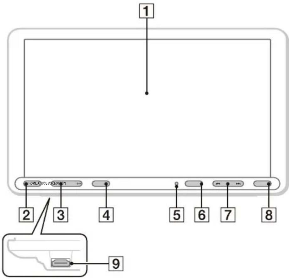
The VOL (volume) + button has a tactile dot.
1 Display/touch screen
2 HOME
Displays the HOME screen (page 6).
STANDBY
Press and hold to turn the unit to standby mode (USB charging is still available). To resume, press any button.
3 VOL (volume) +/-
4 ATT (attenuate)
Attenuates the sound.
To cancel, press again, or press VOL +.
MONITOR OFF
Press and hold to turn off the monitor.
To turn back on, touch any part of the display.
5 Receptor for the remote commander
6 OPTION
Displays the OPTION screen (page 6).
7 ◀◀◀ /▶▶▶ (previous/next)
Functions differently depending on the selected source:
- [Radio]: select a preset station.
- [SXM] (SiriusXM): select a preset channel.
- [USB]/[Bluetooth]: move to the previous/next file.
Press and hold to:
- [Radio]: tune into a station automatically (SEEK+/SEEK-).
- [USB]/[Bluetooth]: fast-reverse/fast-forward.
8 VOICE
Activates the voice command function for Apple CarPlay and Android Auto™.
9 HDMI terminal (input)
RM-X170 remote commander
The remote commander can be used to operate the audio controls. For menu operations, use the touch screen.
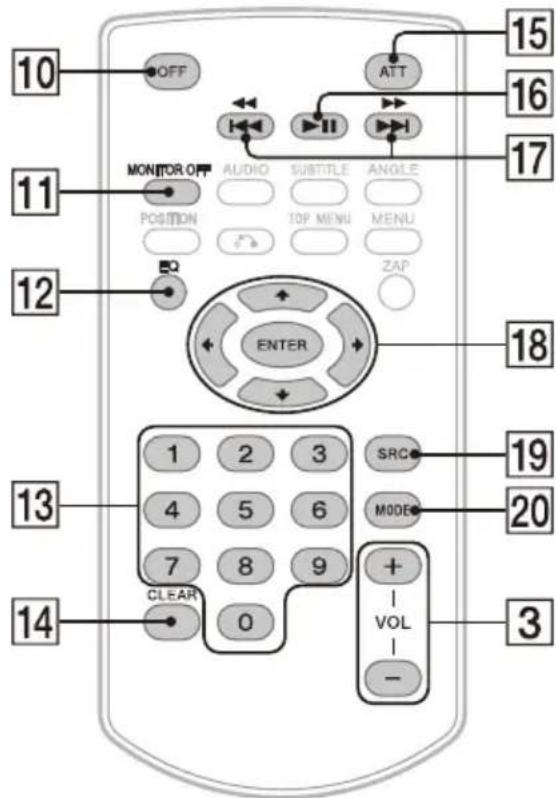
Note
The white buttons in the illustration above are not supported.
10
OFF
Turns the source off.
11
MONITOR OFF
Turns off the monitor.
To turn back on, press again.
12
EQ (equalizer)
Selects an equalizer curve.
13
Number buttons (0 to 9)
14
CLEAR
15
ATT (attenuate)
Attenuates the sound. Press again to cancel the attenuation.
16
-Ⅱ (play/pause)
17


Functions differently depending on the selected source:
- [Radio]: select a preset station.
- [SXM] (SiriusXM): select a preset channel.
- [USB]/[Bluetooth]: move to the previous/next file.
Press and hold to:
- [Radio]: tune into a station automatically (SEEK+/SEEK-).
- [USB]/[Bluetooth]: fast-reverse/fast-forward.
18


Functions differently depending on the selected source.
- [Radio]: select a preset station or tune into a station automatically.
- [SXM] (SiriusXM): select a preset channel or move to the previous/next channel.
- [USB]: select a folder or move to the previous/next file.
ENTER
Enters the selected item.
19
SRC (source)
Changes the source. Each time you press this button, a selectable source is displayed in a popup on the current display.
20
MODE
Selects the radio band.
Remove the insulation film before use.
natural_image
Line drawing of a mobile phone with circular buttons and a card slot (no text or symbols)Screen Displays
Playback screen:
HOME screen:

flowchart
graph TD
    A["4"] --> B["5"]
    B --> C["6"]
    C --> D["7"]
    D --> A
    style A fill:#ccc,stroke:#333
    style B fill:#ccc,stroke:#333
    style C fill:#ccc,stroke:#333
    style D fill:#ccc,stroke:#333
OPTION screen:
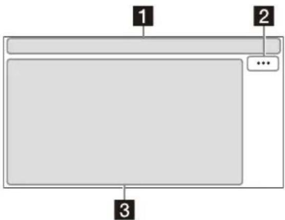
1 Status indication
| ATT | Lights up when the sound is attenuated. |
| SXM | Indicates the signal strength status of the connected SiriusXM Connect Vehicle Tuner. |
| Lights up when the Bluetooth® signal is on. Flashes when the connection is in progress. | |
| Lights up when the audio device is playable by enabling the A2DP (Advanced Audio Distribution Profile). | |
| Lights up when handsfree calling is available by enabling the HFP (Handsfree Profile). | |
| Indicates the signal strength status of the connected mobile phone. | |
| Indicates the remaining battery status of the connected mobile phone. |
2 ...(source option)
Opens the source option menu. The available items differ depending on the source.
3 Application specific area
Displays playback controls/indications or show the unit's status. Displayed items differ depending on the source.
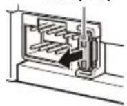
4 Clock
Displays the time which are set on the Date/Time setting.
5 i(instruction for smartphone connection)
Displays the instruction for connecting Apple CarPlay, Android Auto or WebLink™.
6 (return to the playback screen)
Switches from the HOME screen to the playback screen.
7 Sources and Settings select keys
Changes the source or make various settings. Flick to select the setting icon and other icons. Touch the source icon you want to select.
| [KEXX4] | Android Auto | Apple CarPlay | Radio | ||
| [DH20] | SXM Bluetooth HDMI | ||||
 | Rear Camera | USB WebLink | |||
 | Phone Setting | ||||
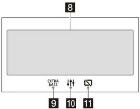
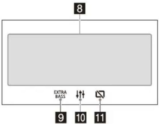
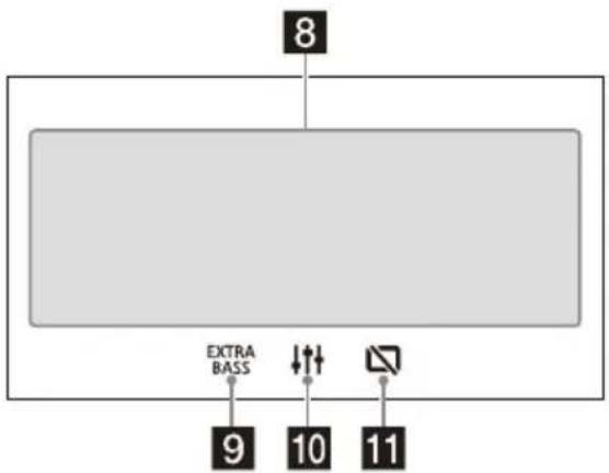
8 Sound select keys
Changes the sound.
9 EXTRE BASS(EXTRA BASS)
Changes the EXTRA BASS setting.
Changes the EQ10/Subwoofer setting.
11 (monitor off)
Turns off the monitor. When the monitor is turned off, touch any part of the display to turn it back on.
Basic Operations
Pairing with a BLUETOOTH Device
When connecting a BLUETOOTH device for the first time, mutual registration (called "pairing") is required. Pairing enables this unit and other devices to recognize each other.
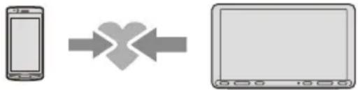
flowchart
graph LR
    A["Mobile Device"] --> B["X-shaped Arrow"]
    B --> C["Computer"]
1 Press HOME, then touch [Settings] → [Bluetooth] → [Bluetooth Connection] → [ON] → [Pairing].
☒ flashes while the unit is in pairing standby mode.
2 Perform pairing on the BLUETOOTH device so it detects this unit.
3 Select your model name shown on the display of the BLUETOOTH device*. When pairing is made, stays lit.
* If passkey input is required on the BLUETOOTH device, input [0000].
Connecting Rear View Camera
By connecting the optional rear view camera to the CAMERA IN terminal, you can display the picture from the rear view camera. For details, see "Connection/Installation" (page 11).
To display the picture from the rear view camera
Press HOME, then touch [Rear Camera].
Canceling the Demonstration Mode
1 Press HOME, then touch [Settings].
2 Touch [General], then touch [Demo] to set to [OFF].
3 To exit the setup menu, touch (back) twice.
Updating the Firmware
To update the firmware, visit the support site, then follow the online instructions.
URL: https://www.sony.com/am/support
Note
During the update, do not remove the USB device.
Additional Information
Precautions
- Power antenna (aerial) extends automatically.
- When you transfer ownership or dispose of your car with the unit installed, initialize all the settings to the factory settings by performing the factory reset.
- Do not splash liquid onto the unit.
Notes on safety
- Comply with your local traffic rules, laws, and regulations.
-
While driving
-
Do not watch or operate the unit, as it may lead to distraction and cause an accident. Park your car in a safe place to watch or operate the unit.
- Do not use the setup feature or any other function which could divert your attention from the road.
- When backing up your car, be sure to look back and watch the surroundings carefully for your safety even if the rear view camera is connected. Do not depend on the rear view camera exclusively.
- While operating
- Do not insert your hands, fingers, or foreign objects into the unit as it may cause injury or damage to the unit.
- Keep small articles out of the reach of children.
- Be sure to fasten seatbelts to avoid injury in the event of sudden movement of the car.
Preventing an accident
Pictures appear only after you park the car and set the parking brake.
If the car starts moving during video playback, the following caution is displayed and you cannot watch the video.
[Video blocked for your safety.]
Do not operate the unit or watch the monitor while driving.
Notes on LCD panel
- Do not get the LCD panel wet or expose it to liquids. This may cause a malfunction.
- Do not press down hard on the LCD panel as doing so can distort the picture or cause a malfunction (i.e., the picture may become unclear or the LCD panel may be damaged).
- Do not touch the panel with objects other than with your finger as it may damage or break the LCD panel.
- Clean the LCD panel with a dry soft cloth. Do not use solvents such as benzine, thinner, commercially available cleaners, or antistatic spray.
- Do not use the unit outside the temperature range 0ircC to 40ircC (32°F to 104°F).
- If your car was parked in a cold or hot place, the picture may not be clear. However, the monitor is not damaged and the picture will become clear after the temperature in your car becomes normal.
- Some stationary blue, red, or green dots may appear on the monitor. These are called "bright spots" and can happen with any LCD. The LCD panel is precision-manufactured with more than 99.99% of its segments functional. However, it is possible that a small percentage (typically 0.01% ) of the segments may not light up properly. This will not, however, interfere with your viewing.
Notes on the touch screen
- This unit uses a resistive touch screen. Touch the screen directly with your fingertip.
- Multi-touch operation is not supported on this unit.
- Do not touch the screen with sharp objects such as a needle, pen, or fingernail. Operation with a stylus is not supported on this unit.
- Do not let any objects contact the touch screen. If the screen is touched by an object other than your fingertip, the unit may not respond correctly.
- Since glass material is used for the screen, do not subject the unit to strong shock. If cracking or chipping occurs on the screen, do not touch the damaged part as it may cause injury.
- Keep other electrical devices away from the touch screen. They may cause the touch screen to malfunction.

About iPhone
•Compatible iPhone models:
iPhone SE (2nd generation), iPhone 11 Pro Max, iPhone 11 Pro, iPhone 11, iPhone XS Max, iPhone XS, iPhone XR, iPhone X, iPhone 8 Plus, iPhone 8, iPhone 7 Plus, iPhone 7, iPhone SE, iPhone 6s Plus, iPhone 6s, iPhone 6 Plus, iPhone 6, iPhone 5s
- Use of the Made for Apple badge means that an accessory has been designed to connect specifically to the Apple product(s) identified in the badge, and has been certified by the developer to meet Apple performance standards. Apple is not responsible for the operation of this device or its compliance with safety and regulatory standards.
Please note that the use of this accessory with an Apple product may affect wireless performance.
Notice on license
This product contains software that Sony uses under a licensing agreement with the owner of its copyright. We are obligated to announce the contents of the agreement to customers under requirement by the owner of copyright for the software.
For details on software licenses, select [Settings] → [General] → [Open Source Licenses].
Notice on GNU GPL/LGPL applied software
This product contains software that is subject to the following GNU General Public License (hereinafter referred to as "GPL") or GNU Lesser General Public License (hereinafter referred to as "LGPL"). These establish that customers have the right to acquire, modify, and redistribute the source code of said software in accordance with the terms of the GPL or LGPL displayed on this unit.
The source code for the above-listed software is available on the Web.
To download, please access the following URL, then select the model name "XAV-AX8100."
URL: http://www.sony.net/Products/Linux/
Please note that Sony cannot answer or respond to any inquiries regarding the content of the source code.
If you have any questions or problems concerning your unit that are not covered in this Operating Instructions, consult your nearest Sony dealer.
Maintenance
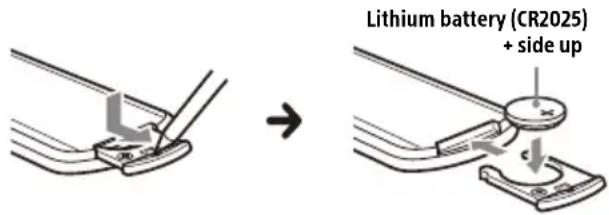
Replacing the lithium battery (CR2025) of the remote commander
When the battery becomes weak, the range of the remote commander becomes shorter.
CAUTION
Danger of explosion if battery is incorrectly replaced. Replace only with the same or equivalent type.
Note on the lithium battery
Keep the lithium battery out of the reach of children. Should the battery be swallowed, immediately consult a doctor.
Specifications
FOR THE CUSTOMERS IN THE USA. NOT APPLICABLE IN CANADA, INCLUDING IN THE PROVINCE OF QUEBEC.
POUR LES CLIENTS AUX ÉTATS-UNIS. NON APPLICABLE AU CANADA, Y COMPRIS LA PROVINCE DE QUÉBEC.
AUDIO POWER SPECIFICATIONS

CTA2006 Standard
Power Output: 20 Watts RMS × 4 at
4 Ohms < 1% THD+N
SN Ratio: 80 dBA (reference: 1 Watt into 4 Ohms)
Monitor section
Display type: Wide LCD color monitor
Dimensions: 8.95 in/227 mm
System: TFT active matrix
Number of pixels:
1,152,000 pixels (800 × 3 (RGB) × 480)
Color system:
PAL/NTSC automatic select for CAMERA IN terminal
Radio section
FM
Tuning range: 87.5 MHz - 107.9 MHz
Usable sensitivity: 7 dBf
Signal-to-noise ratio: 70 dB (mono)
Separation at 1 kHz: 45 dB
AM
Tuning range: 530 kHz - 1,710 kHz
Sensitivity: 32 μV
USB player section
Interface:
USB port: USB (Hi-speed)
Maximum current: 1.5 A
HDMI section\*
Input format: 480p, 576p, 720p
* HDMI output is not available.
Wireless communication
Communication System:
BLUETOOTH Standard version 3.0
Output:
BLUETOOTH Standard Power Class 2
(Max. Conducted +1 dBm)
Maximum communication range *1 :
Line of sight approx. 10 m (33 ft)
Frequency band:
2.4 GHz band (2.4000 GHz - 2.4835 GHz)
Modulation method: FHSS
Compatible BLUETOOTH Profiles 2 :
A2DP (Advanced Audio Distribution Profile) 1.3
AVRCP (Audio Video Remote Control Profile) 1.3 HFP (Handsfree Profile) 1.6
PBAP (Phone Book Access Profile) 1.1
Corresponding codec: SBC, AAC
*1 The actual range will vary depending on factors such as obstacles between devices, magnetic fields around a microwave oven, static electricity, reception sensitivity, antenna (aerial) performance, operating system, software application, etc.
*2 BLUETOOTH standard profiles indicate the purpose of BLUETOOTH communication between devices.
Power amplifier section
Outputs: Speaker outputs
Speaker impedance: 4 Ω - 8 Ω
Maximum power output: 55 W × 4 (at 4 Ω)
General
Power requirements: 12 V DC car battery (negative ground (earth))
Rated current consumption: 10 A
Dimensions (maximum):
Approx. 229 mm × 136 mm × 253 mm
(9 1/8 in × 5 3/8 in × 10 in) (w/h/d)
Mounting dimensions:
Approx. 182 mm × 53 mm × 160 mm
(7 1/4 in × 2 1/8 in × 6 3/8 in) (w/h/d)
Mass: Approx. 2.4 kg (5 lb 5 oz)
Package contents:
Main unit (1)
Parts for installation and connections (1 set)
Remote commander (1): RM-X170
Optional accessories/equipment:
SiriusXM Connect Vehicle Tuner: SXV100, SXV200, SXV300
Ask the dealer for detailed information.
Design and specifications are subject to change without notice.
Copyrights
((SiriusXM) READY
SiriusXM-Ready® allows you to Listen to ad-free music, plus all the sports, talk, comedy, news coverage, all in one place. (SiriusXM Connect Tuner and subscription required. Sold separately.) For more information, visit www.siriusxm.com. Sirius, XM and all related marks and logos are trademarks of Sirius XM Radio Inc. All rights reserved.
The Bluetooth ® word mark and logos are registered trademarks owned by Bluetooth SIG, Inc. and any use of such marks by Sony Corporation is under license. Other trademarks and trade names are those of their respective owners.
Windows Media is either a registered trademark or trademark of Microsoft Corporation in the United States and/or other countries.
This product is protected by certain intellectual property rights of Microsoft Corporation. Use or distribution of such technology outside of this product is prohibited without a license from Microsoft or an authorized Microsoft subsidiary.
Apple and iPhone are trademarks of Apple Inc., registered in the U.S. and other countries. Apple CarPlay is a trademark of Apple Inc.
Android Auto is a trademark of Google LLC.
WebLink is a registered trademark of Abalta Technologies, Inc. in the U.S. and a trademark in the other countries.
The terms HDMI, HDMI High-Definition Multimedia Interface, and the HDMI Logo are trademarks or registered trademarks of HDMI Licensing Administrator, Inc.
All other trademarks are trademarks of their respective owners.
Connection/Installation
Cautions
- Do not install this unit in a car that has no ACC position. The display of the unit does not turn off even after turning the ignition off, and this causes battery drain.
- Run all ground (earth) leads to a common ground (earth) point.
- Do not get the leads trapped under a screw or caught in moving parts (e.g., seat railing).
- Before making connections, turn the car ignition off to avoid short circuits.
- Connect the yellow and red power supply leads only after all other leads have been connected.
- Be sure to insulate any loose unconnected leads with electrical tape for safety.
- Choose the installation location carefully so that the unit will not interfere with normal driving operations.
- Avoid installing the unit in areas subject to dust, dirt, excessive vibration, or high temperature, such as in direct sunlight or near heater ducts.
- Use only the supplied mounting hardware for a safe and secure installation.
- Be sure to use the supplied USB extension cables.
- This unit may not be installed properly depending on the car type. For details on the mounting space, see "Ensuring the mounting location of the unit" (page 12).
- To avoid injury, be careful not to drop the display during installation.
- When installing, be careful not to cut off your fingers with the metal parts of the brackets and mounting base.
- Do not pinch your fingers when attaching the display to the unit.
- Do not install the unit in a position where the unit interferes with driving operations (such as in positions where the shift lever hits the unit, or the hazard button cannot be pressed).
- When using the unit for a long period of time, there may be a possibility that the screws securing the display may come loose. Periodically tighten these screws.
- Do not make any changes or modifications to the unit other than those described in this manual.
Note on the power supply lead (yellow)
When connecting this unit in combination with other stereo components, the amperage rating of the car circuit to which the unit is connected must be higher than the sum of each component's fuse amperage rating.
Note on installing in cars with a start-stop system
The unit may restart when starting the engine from start-stop. In this case, turn off the start-stop system of your car.
Note on installing in cars with electric parking brake system
For cars with electric parking brakes, some related functions (such as video blocking function) may not work properly.
Mounting angle adjustment
Adjust the mounting angle to less than 30irc .
Ensuring the mounting location of the unit
Before installing the unit, consult the installer for details on the installation of the unit and the display.
- Make sure that the distance from the front surface (reference surface) of the mounted unit to the surface of your car's center cluster is within 22 mm (7/8 in). If exceeded, the unit cannot be installed properly.
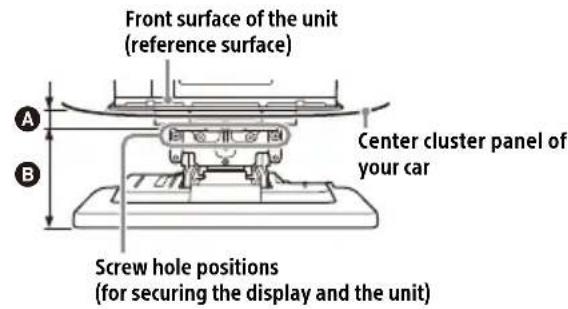
A 22 mm (7/8 in) B 51 mm to 71 mm (2 1/8 in to 2 7/8 in)
- For your safety, adjust the mounting location of the unit so that it does not interfere with driving operations such as button (switch) or shift lever operations.
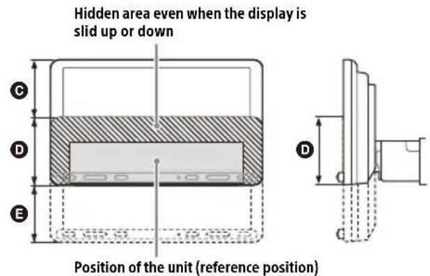
C 60 mm (2 3 /8 in) D 76 mm (3 in) E 60 mm (2 3 /8 in)
Parts List for Installation
① Power supply leads (1)
② Mounting screw (5 × max. 9 mm (7/32 × max. 3/8 in)) (4)

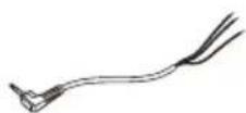
③ Microphone (1)
④ Flat-mount base (1)

⑤ Double-sided tape (1)
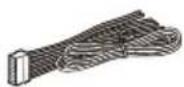
⑥ USB extension cable (long) (1)


⑦ USB extension cable (short) (1)
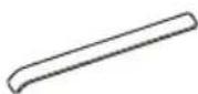
⑧ Cable tie (1)

⑨ Connection cable RC-SR1 (1)
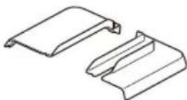
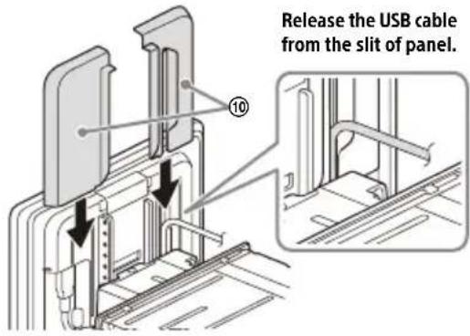
⑩ Rear panel cover (left/right) (2)
⑪ Joint cover (1)
⑫ Fixing screw (for the joint cover) (3 × 8 mm (1/8 × 11/32 in)) (1)

⑬ Fixing screw (for the joint part) (4 × 6 mm (3/16 × 1/4 in)) (4)

This parts list does not include all the package contents.
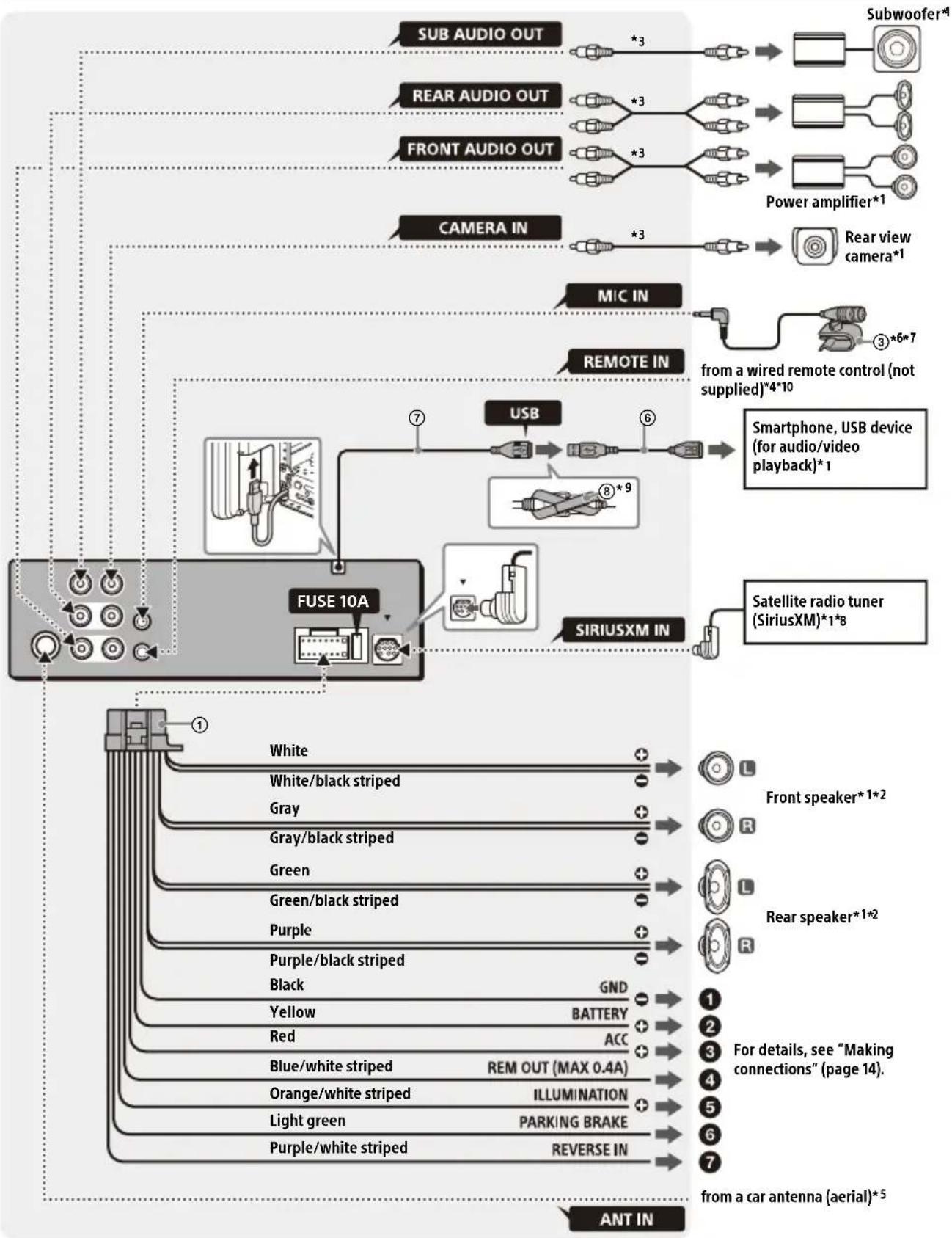
Connection
• To prevent short circuits, insulate leads with a cover or tape.
- Note that the unit may be damaged if it is connected incorrectly or by short circuits at the leads.
flowchart
graph TD
    A["ANT IN"] --> B["White"]
    A --> C["White/black striped"]
    A --> D["Gray"]
    A --> E["Gray/black striped"]
    A --> F["Green"]
    A --> G["Green/black striped"]
    A --> H["Purple"]
    A --> I["Purple/black striped"]
    A --> J["Black"]
    A --> K["Yellow"]
    A --> L["Red"]
    A --> M["Blue/white striped"]
    A --> N["Orange/white striped"]
    A --> O["Light green"]
    A --> P["Purple/white striped"]
    A --> Q["REVERSE IN"]
    B --> R["Sub AUDIO OUT *3"]
    C --> S["REAR AUDIO OUT *3"]
    D --> T["FRONT AUDIO OUT *3"]
    E --> U["CAMERA IN *3"]
    F --> V["MIC IN"]
    G --> W["REMOTE IN"]
    H --> X["USB"]
    I --> Y["SIRIUSXM IN"]
    J --> Z["Subwoofer*1"]
    K --> AA["Power amplifier*1"]
    L --> AB["Rear view camera*1"]
    M --> AC["3*6*7"]
    N --> AD["from a wired remote control (not supplied)*4*10"]
    O --> AE["Smartphone, USB device (for audio/video playback)*1"]
    P --> AF["Satellite radio tuner (SiriusXM)*1*8"]
    Q --> AG["Front speaker*1*2"]
    Q --> AH["Rear speaker*1*2"]
    Q --> AI["For details, see "Making connections" (page 14)"]
    Q --> AJ["from a car antenna (aerial)*5"]
*1 Not supplied
*2 Speaker impedance: 4 Ω to 8 Ω × 4
*3 RCA pin cord (not supplied)
*4 Depending on the type of car, use an adaptor for a wired remote control (not supplied).
For details on using the wired remote control, see "Using the wired remote control" (page 15).
*5 Depending on the type of car, use an adaptor (not supplied) if the antenna (aerial) connector does not fit.
*6 Whether in use or not, route the microphone input cord so it does not interfere with driving operations. Secure the cord with a clamp, etc., if it is installed around your feet.
*7 For details on installing the microphone, see "Installing the microphone" (page 14).
*8 For more information on how to install the SiriusXM Connect Vehicle Tuner, consult the installation guide included with the tuner.
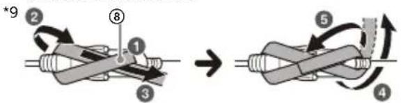
flowchart
graph TD
    A["Step 1: Initial spring component"] --> B["Step 2: Rotation arrow"]
    B --> C["Step 3: Rolling rod with end"]
    C --> D["Step 4: Rotation arrow"]
    D --> E["Step 5: Rotation arrow"]
    E --> F["Step 6: Rotation arrow"]
    F --> G["Step 7: Rotation arrow"]
    G --> H["Step 8: Rotation arrow"]
    H --> I["Step 9: Rotation arrow"]
*10 When using the steering wheel remote control, use the connection cable RC-SR1 ⑨ as necessary.
Making connections
① To a common ground (earth) point
First connect the black ground (earth) lead then connect the yellow and red power supply leads.
② To the +12 V power terminal which is energized at all times
Be sure to first connect the black ground (earth) lead to a common ground (earth) point.
3 To the +12 V power terminal which is energized when the ignition switch is set to the accessory position
Be sure to first connect the black ground (earth) lead to a common ground (earth) point.
4 To the power antenna (aerial) control lead or the power supply lead of the antenna (aerial) booster
It is not necessary to connect this lead if there is no power antenna (aerial) or antenna (aerial) booster, or with a manually-operated telescopic antenna (aerial).
To AMP REMOTE IN of an optional power amplifier
This connection is only for amplifiers and a power antenna (aerial). Connecting any other system may damage the unit.
Note
It will take about 10 seconds to shut down the output of REM OUT after the unit is turned off.
⑤ To a car's illumination signal
Be sure to first connect the black ground (earth) lead to a common ground (earth) point.
⑥ To the parking brake switch lead
The mounting position of the parking brake switch lead depends on your car. Be sure to connect the parking brake lead (light green) of the power supply leads ① to the parking brake switch lead.
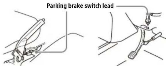
Hand brake type Foot brake type
⑦ To the +12 V power terminal of the car's rear lamp lead (only when connecting the rear view camera)
Memory hold connection
When the yellow power supply lead is connected, power will always be supplied to the memory circuit even when the ignition switch is turned off.
Speaker connection
- Before connecting the speakers, turn the unit off.
- Use speakers with an impedance of 4Ω to 8Ω , and with adequate power handling capacities to avoid damage.
Installing the microphone
To capture your voice during handsfree calling, you need to install the microphone ③.
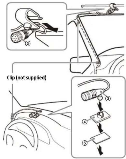
Cautions
- It is extremely dangerous if the cord becomes wound around the steering column or gearstick. Be sure to keep it and other parts from interfering with your driving operations.
- If airbags or any other shock-absorbing equipment are in your car, contact the store where you purchased this unit or the car dealer before installation.
Notes
- When mounting on the dashboard, remove the visor clip carefully from the microphone ③, then attach the flat-mount base ④ to the microphone ③.
- Before attaching the double-sided tape ⑤, clean the surface of the dashboard with a dry cloth.
Using the wired remote control
When using the steering wheel remote control
Installation of the connection cable RC-SR1 ⑨ is required before use.
1 To enable the steering wheel remote control, select [General] → [Steering Control] → [Custom] → ⚙ to make the registration. When the registration is complete, the steering wheel remote control becomes available.
Notes on installing the connection cable RC-SR1 ⑨
- Refer to the support site for details then connect each lead properly to the appropriate leads. Making an improper connection may damage the unit. URL: https://www.sony.com/am/support
- Consulting the dealer or an experienced technician for help is recommended.
When using the wired remote control
1 To enable the wired remote control, set [Steering Control] in [General] to [Preset].
Using the rear view camera
Installation of the rear view camera (not supplied) is required before use.
The picture from a rear view camera connected to the CAMERA IN terminal is displayed when:
- the back lamp of your car lights up (or the shift lever is set to the R (reverse) position).
- you press HOME, then touch [Rear Camera].
Installation
To install the unit and the display securely, be sure to follow the steps ① to ⑦ in order.
① Before mounting the unit (page 15)
② Mounting the unit in the dashboard (page 16)
③ Attaching the joint cover (page 16)
④ Setting up the display (page 16)
⑤ Making sure the mounting positions of the display (page 18)
⑥ Organizing the USB cable (page 18)
⑦ Attaching the display to the unit (page 18)
For your safety
After mounting the display to the unit, make sure that the display does not interfere with normal driving operations such as blocking the driver's view or getting the cables tangled.
① Before mounting the unit
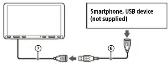
Before mounting the unit in the dashboard, arrange the USB extension cables.
USB cable connection diagram
flowchart
graph TD
    A["Computer"] -->|⑦| B["USB Device"]
    B --> C["USB Device"]
    C --> D["USB Device"]
    D --> E["Smartphone, USB device (not supplied)"]
1 Remove the cable cover, store the USB extension cable (short) ⑦ to the groove of the unit, then attach the cable cover.
Position the USB cable so that its connector (male) comes to the front side of the unit.
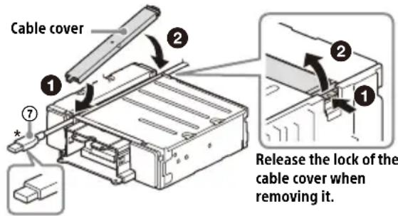
* USB connector (male)
2 Route the USB extension cable (long) ⑥ inside the dashboard, then connect the USB cable (short) ⑦ from the unit.
Position the USB cable so that its connector (male) comes out from the center console panel.
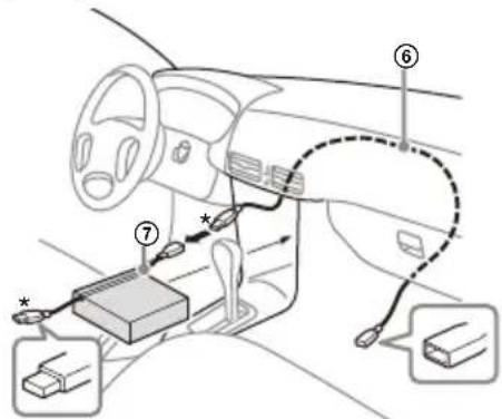
* USB connector (male)
② Mounting the unit in the dashboard
Using the mounting brackets supplied with your car
You may not be able to install this unit in some makes of Japanese cars. In such a case, consult your Sony dealer.
Example
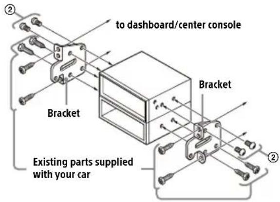
Note
To prevent malfunction, install only with the mounting screws ②.
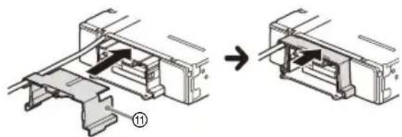
③ Attaching the joint cover
1 Attach the joint cover ⑪ to the mounting base of the unit, then slide it into the unit temporarily.
natural_image
Mechanical assembly diagram showing a component being processed into a housing (no text or symbols present)④ Setting up the display
The mounting positions of the display can be adjusted.
Depth
(within 20 mm
(13 /16 in), in 3 steps)
Height
(within 60 mm
(2 3/8 in), in 7 steps)
Angle
(-10° to +10°, in 3
steps)
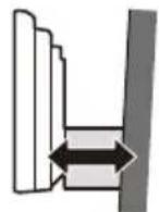
Adjusting the depth of the display position
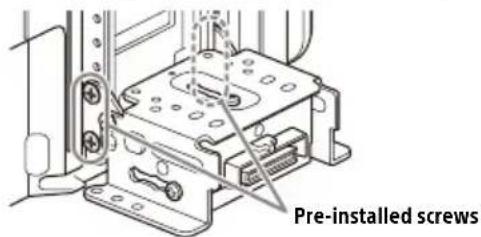
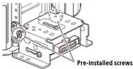
1 Loosen the 3 pre-installed screws for depth adjustment (on top and both sides).
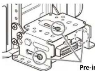
natural_image
Mechanical assembly diagram showing a device with mounting holes and a highlighted component (no text or symbols)Pre-installed screws
Slightly loosen the screws until you can slide the connector bracket. Do not remove the screws from the bracket. Doing so may damage the parts.
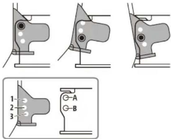
2 Slide the connector bracket to decide the appropriate depth position.
Adjustable depth: within 20 mm (13/16 in) (A), in 3 steps, in 10 mm (13/32 in) pitch (B).
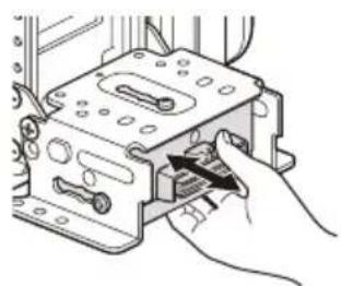
natural_image
Illustration of a hand inserting a component into a device (no text or symbols visible)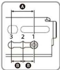
Bracket positions 1 to 3 for the display:
1: Slide-out position
2: Intermediate position
3: Slide-in position
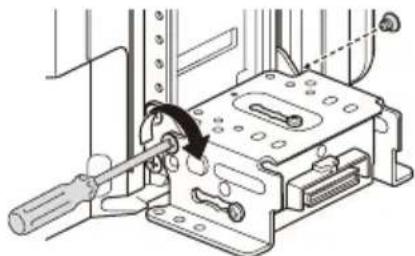
3 At the desired position, tighten the 3 screws firmly to secure the connector bracket.
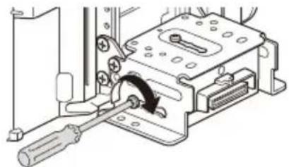
natural_image
Mechanical assembly diagram showing a screwdriver inserted into a housing component (no text or symbols visible)Tighten the screws firmly. When you tighten a screw, be careful not to apply too much torque as doing so may damage the screw (the torque value should be from 1.2 N•m to 1.5 N•m).
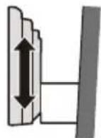
Adjusting the height of the display position
1 Remove the 4 pre-installed screws for height adjustment (on both sides).
2 Slide the connector bracket up or down to decide the appropriate height position. Adjustable height: within 60 mm (2 3 /8 in) (A), in 7 steps, in 10 mm (13/32 in) pitch (B).
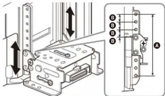
3 At the desired position, tighten the 4 screws firmly to secure the connector bracket.
natural_image
Technical line drawing of a mechanical assembly with no visible text or symbolsTighten the screws firmly. When you tighten a screw, be careful not to apply too much torque as doing so may damage the screw (the torque value should be from 1.2 N•m to 1.5 N•m).
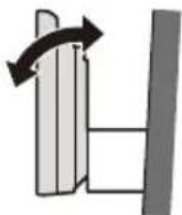
Adjusting the display angle (tilt)
1 Remove the 2 pre-installed screws for angle adjustment (on both sides).
2 Adjust the display angle to decide the appropriate angle.
Adjustable angle: -10irc to +10irc , in 3 steps
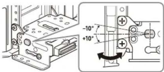
Screw holes to use:
0 ^ irc (1 - A) - 1 0 ^ irc (3 - B) + 1 0 ^ irc (2 - B)
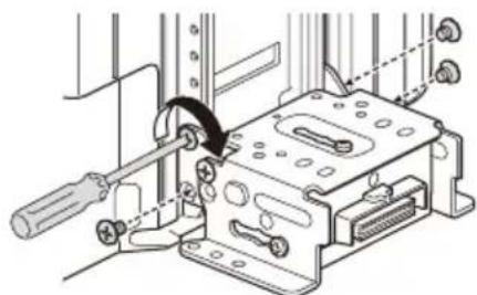
3 At the desired angle, tighten the 2 screws through the screw holes (upper or lower) that match the display angle.
natural_image
Mechanical assembly diagram showing a tool inserted into a housing with a curved arrow indicating motion (no text or symbols present)Tighten the screws firmly. When you tighten a screw, be careful not to apply too much torque as doing so may damage the screw (the torque value should be from 1.2 N•m to 1.5 N•m).
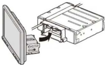
⑤ Making sure the mounting positions of the display
Be careful not to pinch your fingers or scratch the center cluster panel of your car when attaching the display to the unit.
1 Attach the display to the unit temporarily.
natural_image
Diagram of a computer interface showing a monitor and internal components with an arrow indicating a process (no text or symbols present)2 Confirm that the display does not block the driver's view or interfere with normal driving operations.
If further adjustment of the mounting position (depth, height, angle) is necessary, remove the display from the unit, then adjust it again accordingly.
⑥ Organizing the USB cable
1 Connect the USB extension cable (short) ⑦ to the USB port of the display, then route the cable along the groove.
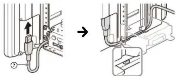
To prevent the extension cable from coming off, be sure to route the USB cable along the groove through the catches inside.
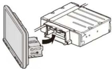
⑦ Attaching the display to the unit
Be careful not to pinch your fingers or scratch the center cluster panel of your car when attaching the display to the unit.
1 Attach the display to the unit.
natural_image
Diagram of a computer monitor connected to an internal device via cable, showing no text or symbolsMake sure that the connector brackets of the display is fully inserted to the unit.
2 Tighten 4 screws ⑬ (on top) to secure the connector bracket to the unit.
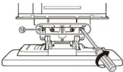
Tighten the screws firmly.
When you tighten a screw, be careful not to apply too much torque as doing so may damage the screw (the torque value should be from 1.2 N•m to 1.5 N•m).
3 Slide the joint cover ⑪ out to protect the mounting base of the display, then tighten the fixing screw ⑫ to secure the cover.
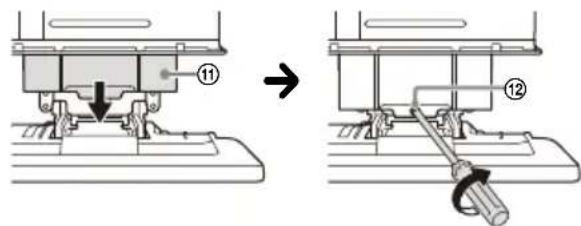
Tighten the screw firmly.
When you tighten a screw, be careful not to apply too much torque as doing so may damage the screw (the torque value should be from 1.2 N•m to 1.5 N•m).
4 Attach the rear panel covers (L, R) ⑩ along the guides for protection.
Fuse replacement
When replacing the fuse, be sure to use one matching the amperage rating stated on the original fuse. If the fuse blows, check the power connection and replace the fuse. If the fuse blows again after replacement, there may be an internal malfunction. In such a case, consult your nearest Sony dealer.
Fuse (10 A)
Avertissement
Communication BLUETOOTH
3 VOL (volume) +/-
4 ATT (atténuation)
Atténue le son.
natural_image
Line drawing of a handheld device with circular buttons and a paper clip (no text or symbols)Écran HOME :
flowchart
graph TD
    A["4"] --> B["5"]
    B --> C["6"]
    D["7"] --> E["←"]
    F["→"] --> G["←"]
    H["←"] --> I["←"]
Écran OPTION :
1 Indication d'état
Norme BLUETOOTH version 3.0
Sortie :
Norme BLUETOOTH Power Class 2
A2DP (Advanced Audio Distribution Profile) 1.3
AVRCP (Audio Video Remote Control Profile) 1.3
HFP (Handsfree Profile) 1.6
PBAP (Phone Book Access Profile) 1.1
Dimensions (maximum):
Environ 229 mm × 136 mm × 253 mm
(9 1/8 po × 5 3/8 po × 10 po) (l/h/p)
Appareil principal (1)
Raccordement/Installation
Mises en garde
flowchart
graph TD
    A["Step 1: Initial string with component 1, labeled ①, ②, ③, ④"] --> B["Step 2: Rotation of part"]
    B --> C["Step 3: Rolling wire with component 3, labeled ③"]
    C --> D["Step 4: Rotation of cable with component 4, labeled ④"]
    D --> E["Step 5: Rotation of cable with component 5, labeled ⑤"]
    E --> F["Step 6: Rotation of cable with component 6, labeled ⑥"]
    F --> G["Step 7: Rotation of cable with component 7, labeled ⑦"]
    G --> H["*9"]
Mises en garde
natural_image
Mechanical assembly diagram showing a bracket with internal components before and after assembly (no text or symbols)natural_image
Technical diagram of a device with labeled ports and components, no readable text or symbols presentVis pré-installées
natural_image
Mechanical assembly diagram showing a tool inserted into a housing component with a curved arrow indicating motion (no text or symbols present)natural_image
Technical line drawing of a mechanical assembly with no visible text or symbolsnatural_image
Three sequential diagrams showing mechanical joint configurations with no text or symbols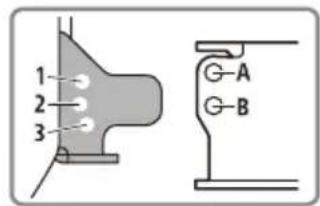
natural_image
Mechanical assembly diagram showing a tool inserted into a housing component with a curved arrow indicating rotation (no text or symbols present)natural_image
Diagram of a computer monitor connected to an internal device, showing internal components and a directional arrow (no text or symbols present)natural_image
Diagram of a computer interface showing an open monitor connected to a rectangular device with internal components (no text or symbols visible)natural_image
Mechanical assembly diagram showing a lever mechanism with a numbered component (no text or symbols present)Serrez fermement la vis.
natural_image
Line drawing of a remote control device with circular buttons and a paper clip (no text or symbols)Pantallas
Pantalla HOME:

flowchart
graph TD
    A["4"] --> B["5"]
    B --> C["6"]
    C --> D["7"]
    D --> A
    style A fill:#ccc,stroke:#333
    style B fill:#ccc,stroke:#333
    style C fill:#ccc,stroke:#333
    style D fill:#ccc,stroke:#333
Pantalla OPTION:
flowchart
graph LR
    A["Mobile Phone"] --> B["X-shaped Arrow"]
    B --> C["Device"]
1 Presione HOME, luego toque [Ajustes] → [Bluetooth] → [Conexión Bluetooth] → [ACTIV.] → [Conectar].
URL: https://www.sony.com/am/support
Nota
flowchart
graph TD
    A["Step 1: Initial state"] --> B["Step 2: Rotation arrow"]
    B --> C["Step 3: Rotation arrow"]
    C --> D["Step 4: Rotation arrow"]
    D --> E["Step 5: Rotation arrow"]
    E --> F["Step 8: Pointing arrow"]
    F --> G["Step 9: Targeted state"]
* Conector USB (macho)
natural_image
Mechanical assembly diagram showing a component being processed into a housing (no text or symbols present)natural_image
Mechanical assembly diagram showing a component with labeled parts and a magnified inset (no readable text or symbols)Tornillos instalados previamente
natural_image
Illustration of a hand inserting a component into a device housing (no text or symbols visible)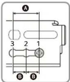
natural_image
Mechanical assembly diagram showing a screwdriver inserted into a housing component (no text or symbols visible)natural_image
Technical line drawing of a mechanical assembly with no visible text or symbolsnatural_image
Technical diagram of a mechanical assembly with labeled component 'Tornill' (no readable text or symbols beyond label)Tornillos instalados previamente
natural_image
Mechanical assembly diagram showing a tool inserted into a housing component with a screwdriver (no text or symbols visible)natural_image
Diagram of a computer monitor connected to an internal device, showing internal components and a directional arrow (no text or symbols present)natural_image
Diagram of a computer interface showing an open monitor and internal components being inserted (no text or symbols present)natural_image
Technical line drawing of a mechanical assembly with no visible text or symbolsIf you have any questions/problems regarding this product, try the following:
1 Read Troubleshooting in Help Guide (online manual).
2 Please contact (U.S.A. only);
Call 1-800-222-7669
URL https://www.SONY.com


Bluetooth®
HDMI TM HIGH-DEFINITION MULTIMEDIA INTERFACE
- Warning
- WARNING: Do not ingest battery, Chemical Burn Hazard.
- Note on the lithium battery
- Warning if your car's ignition has no ACC position
- Disclaimer regarding services offered by third parties
- Important notice
- Caution
- Emergency calls
- On BLUETOOTH communication
- Main Unit and Remote Commander
- Main unit
- RM-X170 remote commander
- Note
- ENTER
- Screen Displays
- ...(source option)
- Application specific area
- Clock
- i(instruction for smartphone connection)
- (return to the playback screen)
- Sources and Settings select keys
- Sound select keys
- EXTRE BASS(EXTRA BASS)
- (monitor off)
- Basic Operations
- Pairing with a BLUETOOTH Device
- Connecting Rear View Camera
- To display the picture from the rear view camera
- Canceling the Demonstration Mode
- Updating the Firmware
- Additional Information
- Precautions
- Notes on safety
- Preventing an accident
- [Video blocked for your safety.]
- Notes on LCD panel
- Notes on the touch screen
- About iPhone
- •Compatible iPhone models:
- Notice on license
- Notice on GNU GPL/LGPL applied software
- Maintenance
- Replacing the lithium battery (CR2025) of the remote commander
- Specifications
- AUDIO POWER SPECIFICATIONS
- Monitor section
- Radio section
- FM
- AM
- USB player section
- HDMI section\*
- Wireless communication
- Power amplifier section
- General
- Copyrights
- ((SiriusXM) READY
- Connection/Installation
- Cautions
- Note on the power supply lead (yellow)
- Note on installing in cars with a start-stop system
- Mounting angle adjustment
- Ensuring the mounting location of the unit
- Parts List for Installation
- Connection
- Making connections
- Memory hold connection
- Speaker connection
- Installing the microphone
- Notes
- Using the wired remote control
- When using the steering wheel remote control
- Notes on installing the connection cable RC-SR1 ⑨
- When using the wired remote control
- Using the rear view camera
- Installation
- For your safety
- ① Before mounting the unit
- ② Mounting the unit in the dashboard
- Using the mounting brackets supplied with your car
- ③ Attaching the joint cover
- ④ Setting up the display
- Adjusting the depth of the display position
- Adjusting the height of the display position
- Adjusting the display angle (tilt)
- ⑤ Making sure the mounting positions of the display
- ⑥ Organizing the USB cable
- ⑦ Attaching the display to the unit
- Fuse replacement
- Avertissement
- Communication BLUETOOTH
- Indication d'état
- Raccordement/Installation
- Mises en garde
- Pantallas
- Nota
Brand : SONY
Model : XAVAX8100
Category : Cd player/recorder