
Tornado 7121 HWSY - Tractor STIGA - Free user manual and instructions
Find the device manual for free Tornado 7121 HWSY STIGA in PDF.

| Product type | Lawn tractor with seated operator |
| Brand | STIGA |
| Model | Tornado 7121 HWSY |
| Engine | 4-stroke petrol engine |
| Transmission | Continuous variable hydrostatic |
| Drive type | 2-wheel drive (2WD) or 4-wheel drive (4WD) depending on version |
| Cutting height | 2 to 10 cm (adjustable in 9 positions) or 3 to 9 cm (adjustable in 7 positions) depending on equipment |
| Cutting width | Not specified in manual |
| Fuel tank capacity | Not specified in manual |
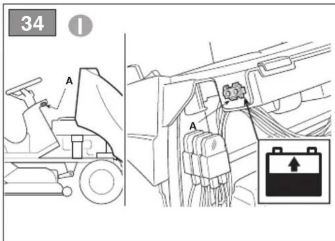
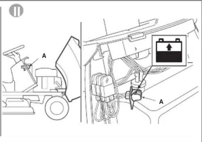
| Battery | 12 V, charge before first use and during periods of inactivity |
| Auxiliary outlet | 12 V, max power 50 W |
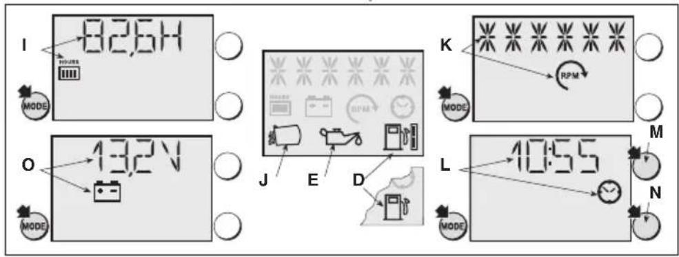
| Hour meter | Yes, displays engine operating hours |
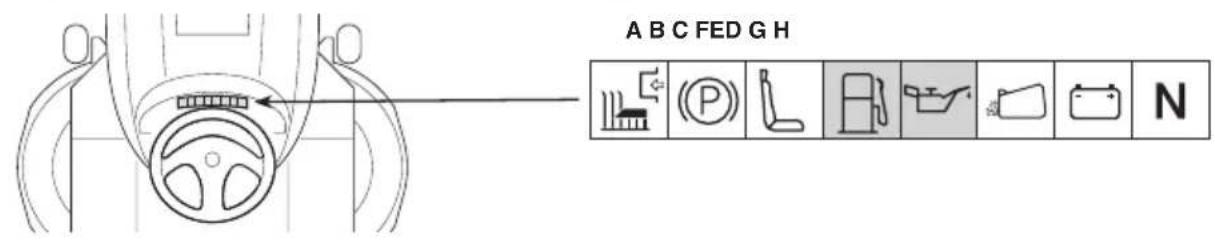
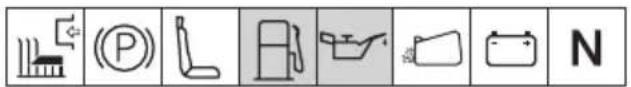
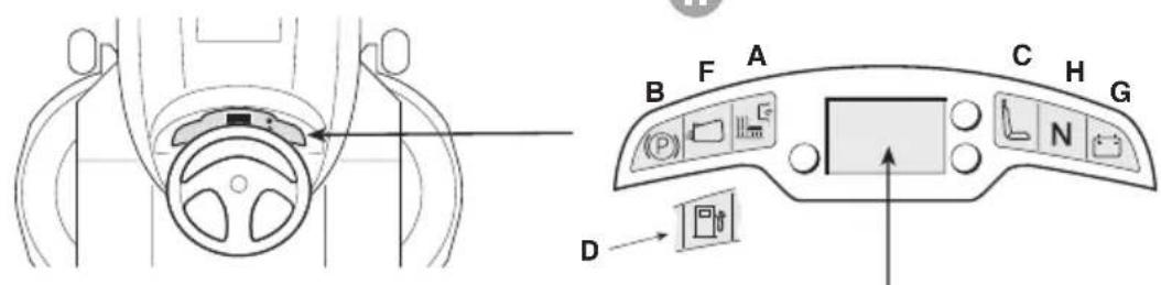
| Display | Type I, II or III depending on version, with visual and audible indicators |
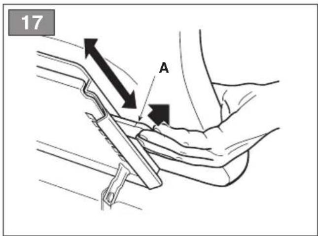
| Seat adjustment | Sliding, 6 positions |
| Parking brake | Yes, lever operated |
| Safety devices | Engine stop if operator absent, brake applied, reverse without authorization, etc. |
| Available accessories | Grass bag, side deflector, mulching kit, trailer, snow plow, etc. |
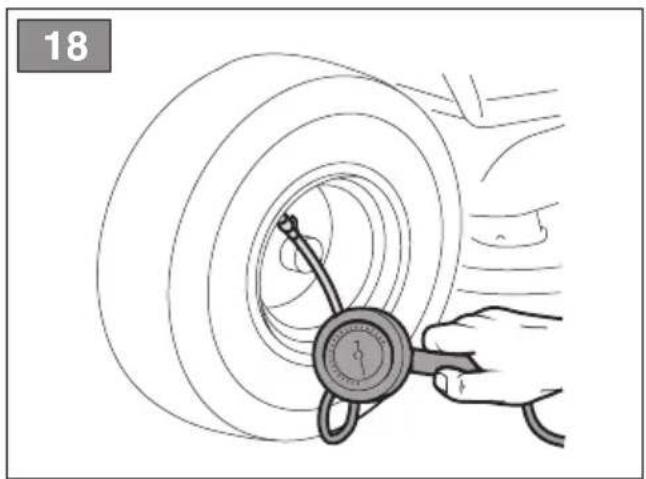
| Tires | Front and rear, specific dimensions and pressures (see manual) |
| Weight | Not specified in manual |
| Periodic maintenance | Oil change, air filter check, blade sharpening, etc. (see maintenance chart) |
Frequently Asked Questions - Tornado 7121 HWSY STIGA
User questions about Tornado 7121 HWSY STIGA
0 question about this device. Answer the ones you know or ask your own.
Ask a new question about this device
Download the instructions for your Tractor in PDF format for free! Find your manual Tornado 7121 HWSY - STIGA and take your electronic device back in hand. On this page are published all the documents necessary for the use of your device. Tornado 7121 HWSY by STIGA.
USER MANUAL Tornado 7121 HWSY STIGA
171506107/6A 10/2019
T* - TC* - TH* 102 Series
108 Series
118 Series
122 Series


natural_image
Abstract line drawing of a stylized animal or creature (no text or symbols)EN Ride-on lawnmower with seated operator - OPERATOR'S MANUAL WARNING: read thoroughly the instruction booklet before using the machine.
16
1
11
三
natural_image
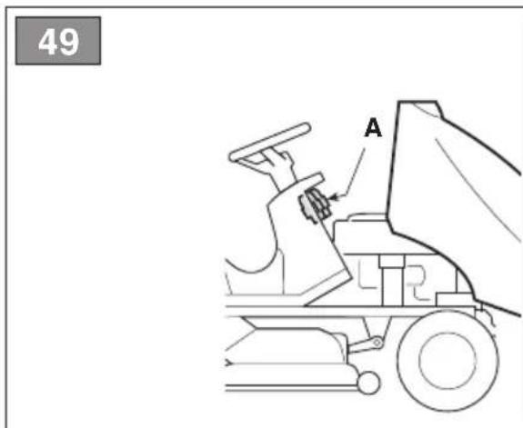
Diagram of a car interior showing steering wheel and dashboard (no text or symbols)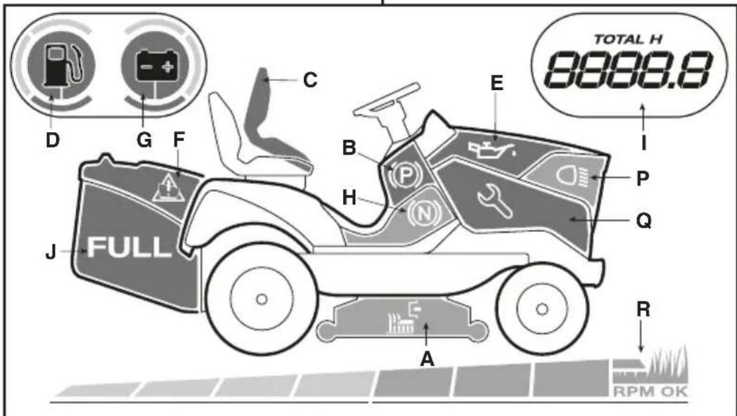
natural_image
Illustration of a hand holding a car tire with a dial, no text or symbols present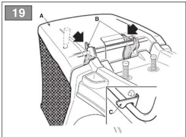
natural_image
Technical line drawing of a mechanical component with motion lines and a directional arrow (no text or symbols)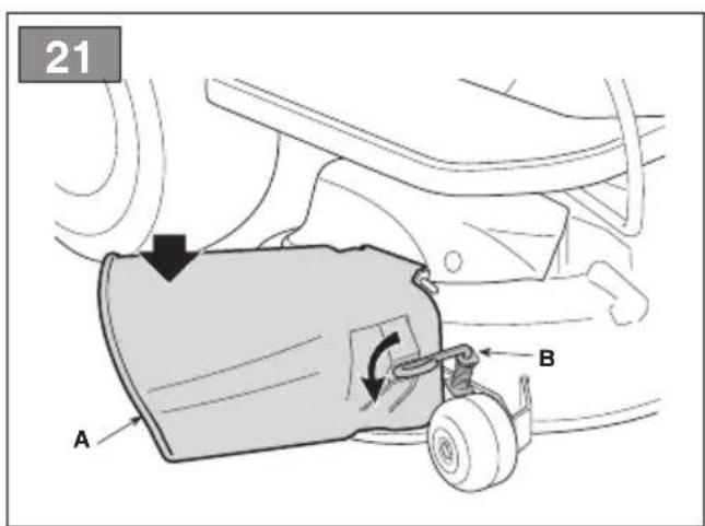
natural_image
Illustration of hands using a tool to adjust or install a car wheel (no text or symbols visible)


58
natural_image
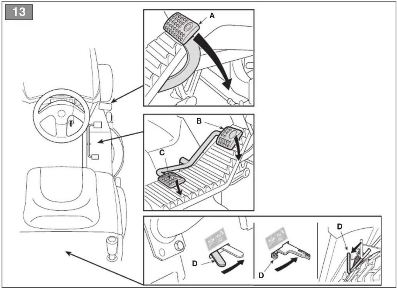
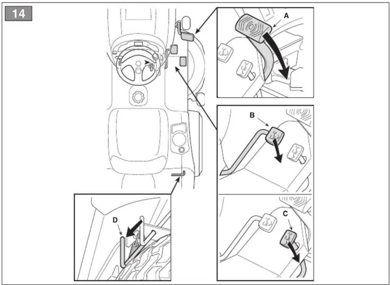
Technical diagram of a mechanical assembly with labeled component A1 (no readable text or symbols)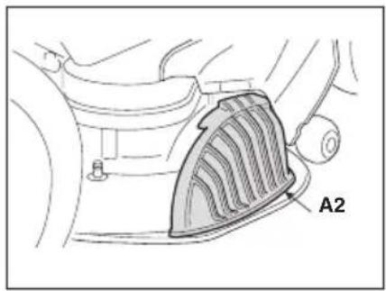
natural_image
Illustration of a portable electronic device with a labeled component 'B' and wiring (no text or symbols on the device itself)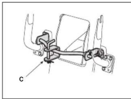
natural_image
Mechanical assembly diagram showing a linkage mechanism with labeled component 'C' (no text or symbols beyond label)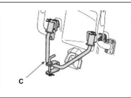
natural_image
Mechanical assembly diagram showing a bracket with mounting feet and a labeled component 'C' (no text or symbols beyond label)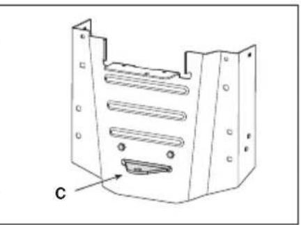
natural_image
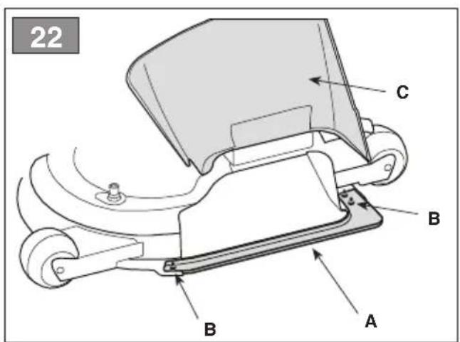
Technical line drawing of a mechanical housing component with labeled part 'C' (no text or symbols beyond label)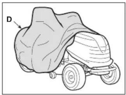
natural_image
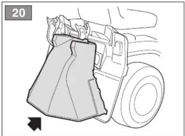
Illustration of a covered outdoor vehicle with a dome-shaped hood and wheels (no text or symbols)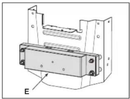
natural_image
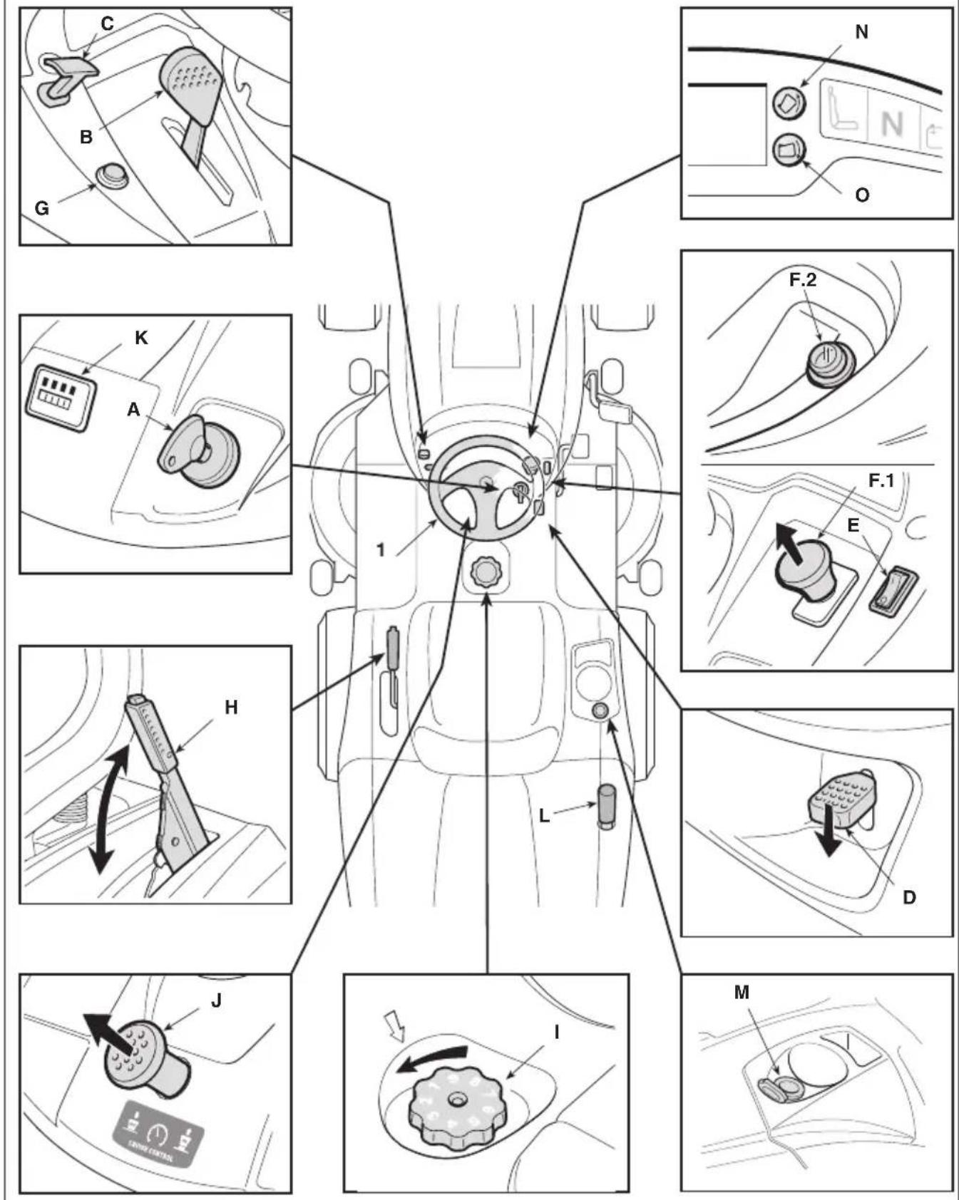
Technical line drawing of a mechanical component with mounting holes and a labeled section E (no text or symbols beyond label)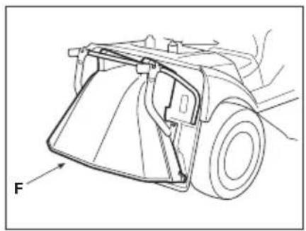
natural_image
Technical line drawing of a vehicle's front wheel assembly (no text or symbols)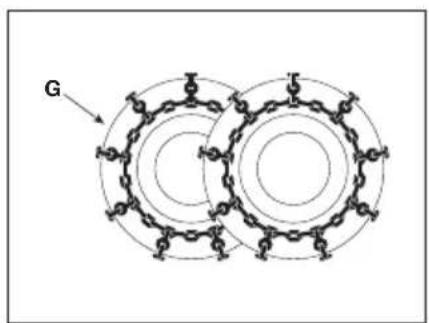
natural_image
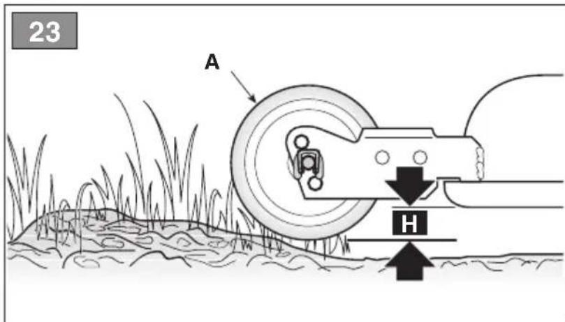
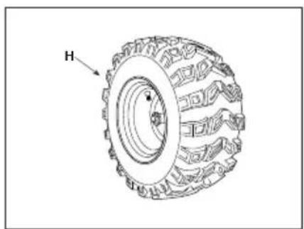
Technical line drawing of a tire with labeled component H (no text or symbols beyond label)58
natural_image
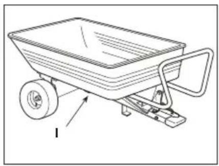
Line drawing of a wheelbarrower with a handle and wheels, no text or symbols present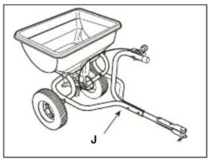
natural_image
Technical line drawing of a manual pushrower with labeled component J (no text or symbols beyond label)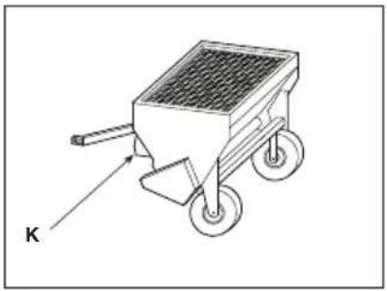
natural_image
Illustration of a wheeled cart with wheels and a labeled component 'K' (no text or symbols on the cart itself)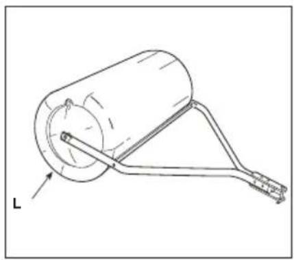
natural_image
Technical line drawing of a cylindrical mechanical component with a lever and base, labeled 'L' (no text or symbols beyond label)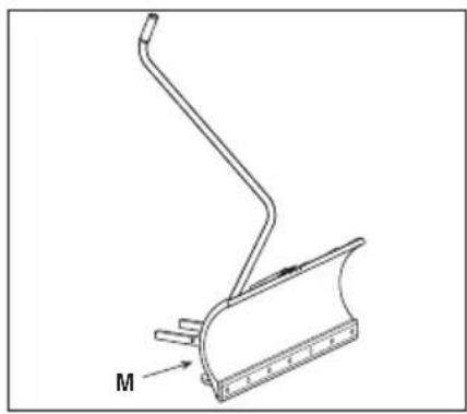
natural_image
Technical line drawing of a mechanical component with a curved base and attached rod (no text or symbols)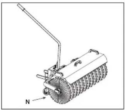
natural_image
Technical line drawing of a mechanical brush or scraper with a labeled component 'N' (no text or symbols beyond label)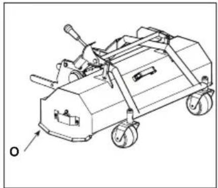
natural_image
Technical line drawing of a wheeled cart with wheels and a handle, labeled 'O' (no text or symbols on the vehicle itself)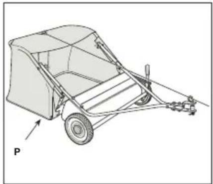
natural_image
Technical line drawing of a wheeled cart with a pulley and wheels, labeled 'P' (no text or symbols on the diagram itself)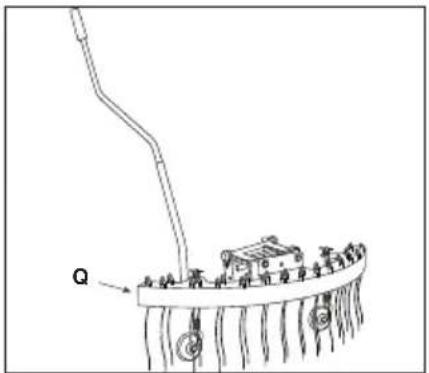
natural_image
Technical line drawing of a mechanical bracket component (no text or symbols)[4] Electrical system
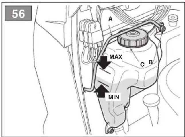
[5] Fuel tank capacity
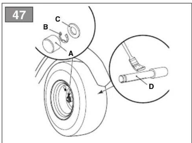
[6] Front tyres
[7] Rear tyres
[8] Front tyre pressure
[9] Rear tyre pressure
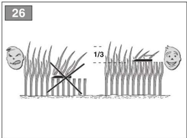
[10]Cuttingheight
[11] Cutting width
[12] Minimum radius of uncut grass
[13] Cutting means part n.
[14] Forward speed (indicative) at 3000 min-1
[15] Speed limit with snow chains (if fitted)
[16] Loading limit for towing device (Maximum vertical force)
[17] Loading limit for towing device (Permissible towing weight)
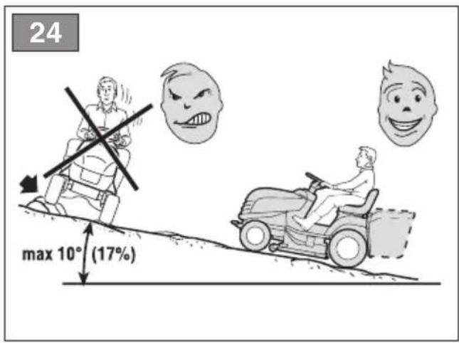
[18] Maximum permissible gradient
[19] Dimensions
[20]Length
[21] Length with catcher bag (Length without catcher bag)
[22]Width
[23] Width with side discharge chute (Width without side discharge chute)
[24]Height
[25] Mass *
[26] Sound pressure level (max.)
[27] Measurement uncertainty
[28] Measured acoustic power level (max.)
[29] Guaranteed acoustic power level
[30] Vibration level at driver's position (max.)
[31] Vibration level at steering wheel (max.)
[32] Attachment compatibility table
[32.A] Rear attachments
[32.B] Front attachments
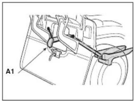
[58] Optional attachments
[58.A1, 58.A2] "Mulching" kit
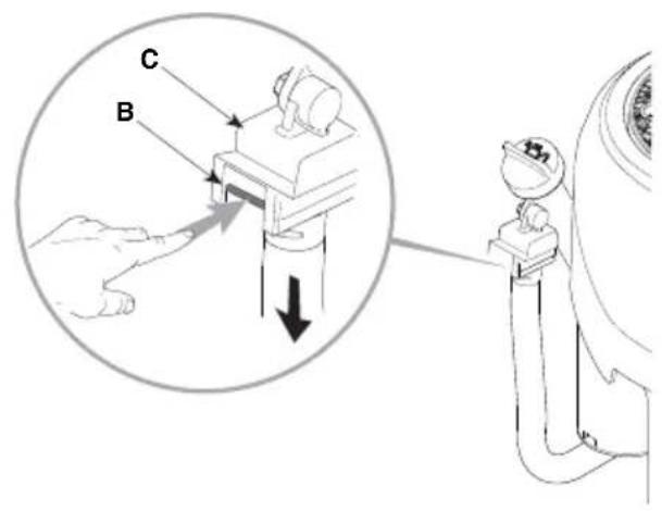
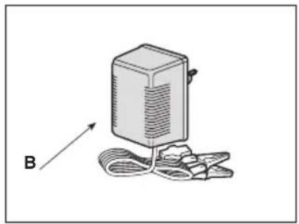
[58.B] Battery float charger
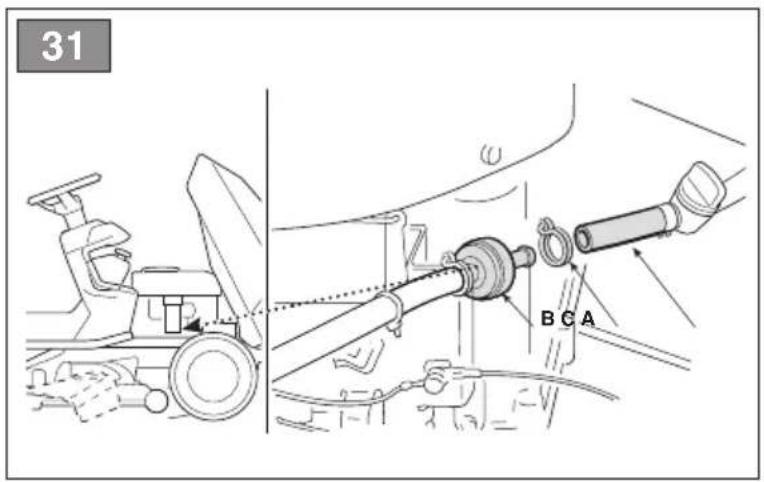
[58.C] Towing kit
[58.D] Protective canvas cover
[58.E] Rear weights kit
[58.F] Rear discharge safety kit (models with rear grass catcher only)
[58.G] Snow chains (18", 20")
[58.H] Snow/mud wheels (18", 20")
[58.1]Trailer
[58.J, 58.K] Sprinkler
[58.L]Grassroller
[58.M] Snow blade
[58.N] Front sweeper
[58.O]Shredder
[58.P] (For SD series models only) Leaf and collector 38" Leaf and collector 42"
[58.Q] Front rake
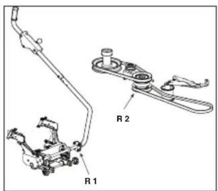
[58.R1, 58.R2] Lifting interface + Power Take-Off (PTO)
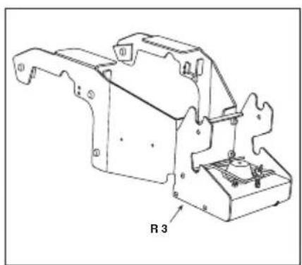
[58.R3] Power Take-Off (PTO)
* For specific information, refer to the information on the machine identification label.
[1] ES - DATOS TÉCNICOS
[2] Potencia nominal
[32.A] Tagumised tarvikud
[32.B] Eesmised tarvikud
[58] Valikulised tarvikud
[58.A1, 58.A2] Multšimiskomplekt
[1] FI - TEKNISET TIEDOT
[2] Nimellisteho
[1] LT - TECHNINIAI DUOMENYS
[2] Vardinè galia
[58.R1, 58.R2] Lift-interface + Aftakas (PTO)
[58.R3] Aftakas (PTO)
[58.A1, 58.A2] Sett for "mulching"
[58.L] Walec do trawy
[58.M] Pług śnieżny
[58.Q] Grade frontal
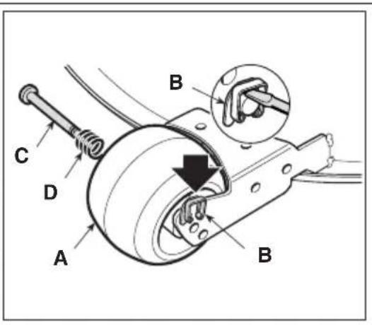
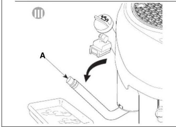
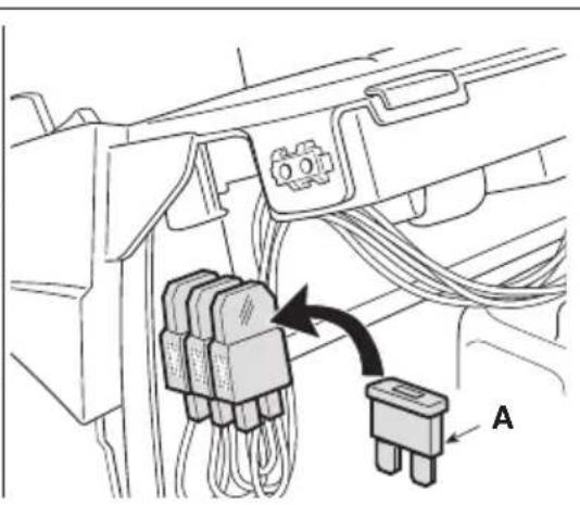
8.5 REMPLACEMENT D'UN FUSIBLE
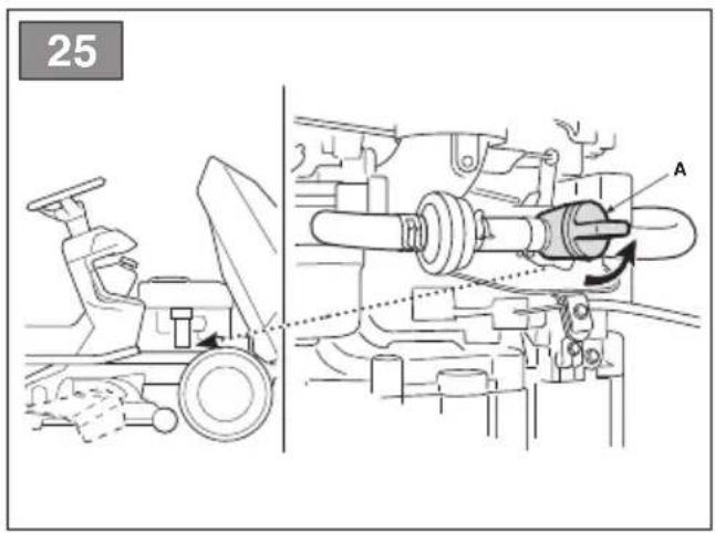
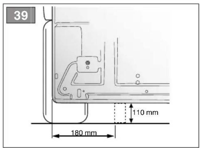
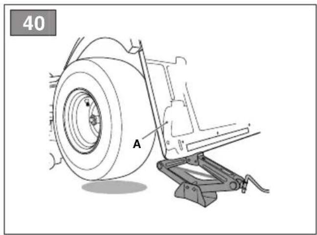
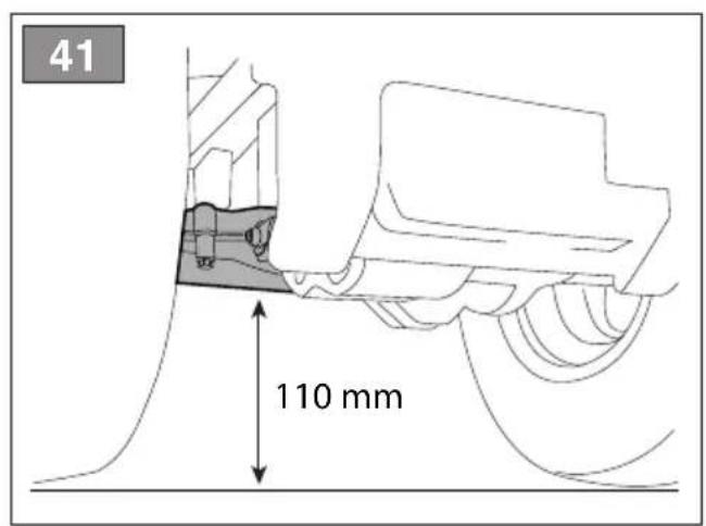
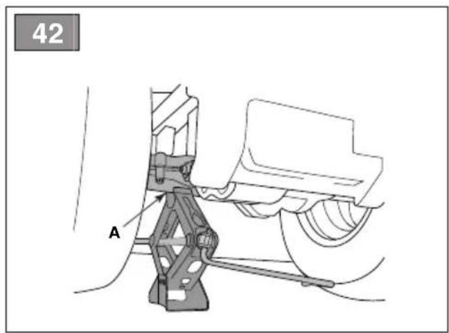
10. MANUTENTION ET TRANSPORT
CEO Stiga Group Sean Robinson
Sunn Rob
CEO Stiga Group Sean Robinson
Sunn Rob
EN • The content and images in this User Manual were produced expressly for ST. S.p.A. and are protected by copyright – any unauthorised reproduction or modification to the document, either partially or in full, is prohibited.
Type:

Brand : STIGA
Model : Tornado 7121 HWSY
Category : Tractor