
PTLB2U - Projector PANASONIC - Free user manual and instructions
Find the device manual for free PTLB2U PANASONIC in PDF.

| Product type | LCD projector |
| Technology | LCD (3-panel) |
| Native resolution | XGA (1024 x 768) |
| Lamp | High-pressure mercury lamp (model ET-LAB2) |
| Lamp life | Approx. 4,000 hours (reference) |
| Power supply | 100-240 V AC, 50/60 Hz |
| High altitude mode | Yes, up to 2,700 m (set to YES if altitude > 1,400 m) |
| Ceiling mount | Possible with optional ceiling mount kit ET-PKB2 |
| Air filter maintenance | Regular cleaning; replace if necessary (model TXFKN01VKN5) |
| Lamp replacement | Recommended by a qualified technician |
| Safety | Automatic shutdown in case of overheating (TEMP indicator); safety shutdown if lamp is worn out |
| Supplied accessories | Remote control with batteries, power cord, carrying case, spacer |
| Usage | Indoor use only; do not expose to rain or humidity |
| Recycling | Mercury lamp: follow local disposal regulations |
Frequently Asked Questions - PTLB2U PANASONIC
User questions about PTLB2U PANASONIC
0 question about this device. Answer the ones you know or ask your own.
Ask a new question about this device
Download the instructions for your Projector in PDF format for free! Find your manual PTLB2U - PANASONIC and take your electronic device back in hand. On this page are published all the documents necessary for the use of your device. PTLB2U by PANASONIC.
USER MANUAL PTLB2U PANASONIC
Operating Instructions Basic Manual
LCD Projector
Commercial Use
Model No.
PT-LB2U
PT-LB1U
natural_image
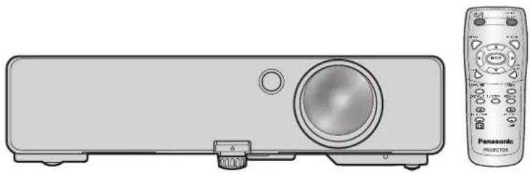
Illustration of a projector and its Panasonic projector (no text or symbols on the device body)Thank you for purchasing a Panasonic Projector.
Before operating this product, please read the instructions carefully, and save this manual ■ for future use.
Before using your projector, be sure to read "Precautions with regard to safety" (pages 5 to 9).
For network operation, please read the Network Operation Manual.
Important Safety Notice
Dear Panasonic Customer:
The following information should be read and understood as it provides details, which will enable you to operate the projector in a manner which is both safe to you and your environment, and conforms to legal requirements regarding the use of projectors. Keep this booklet with your Panasonic LCD projector for future reference. The serial number of your product may be found on its bottom. Write it in the space provided below and retain this booklet in case service is required.
Model number: PT-LB2U/PT-LB1U
Serial number:
WARNING: TO REDUCE THE RISK OF FIRE OR ELECTRIC SHOCK, DO NOT EXPOSE THIS PRODUCT TO RAIN OR MOISTURE.
Power Supply: This LCD Projector is designed to operate on 100 V - 240 V, 50 Hz/60 Hz AC, house current only.
CAUTION: The AC power cord which is supplied with the projector as an accessory can only be used for power supplies up to 125 V, 7 A. If you need to use higher voltages or currents than this, you will need to obtain a separate 250 V power cord. If you use the accessory cord in such situations, fire may result.

WARNING
RISK OF ELECTRIC
SHOCK. DO NOT OPEN

MISE EN GARDE-RISQUE DE CHOC ÉLECTRIQUE. NE PAS OUVRIR.
The lightning flash with arrowhead symbol, within an equilateral triangle, is intended to alert the user to the presence of uninsulated “dangerous voltage” within the product’s enclosure that may be of sufficient magnitude to constitute a risk of electric shock to persons.

The exclamation point within an equilateral triangle is intended to alert the user to the presence of important operating and maintenance (servicing) instructions in the literature accompanying the product.
CAUTION: This equipment is equipped with a three-pin grounding-type power plug.
Do not remove the grounding pin on the power plug. This plug will only fit a grounding-type power outlet. This is a safety feature. If you are unable to insert the plug into the outlet, contact an electrician.
Do not defeat the purpose of the grounding plug.
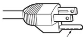
Do not remove
Pursuant to at the directive 2004/108/EC, article 9(2)
Pursuant to at the directive 2005/32/EC amended by 2008/28/EC, article 14
Panasonic Testing Center
Panasonic Service Europe, a division of Panasonic Marketing Europe GmbH
Winsbergring 15, 22525 Hamburg, F.R. Germany
NOTICE:
This product has a High Intensity Discharge (HID) lamp that contains mercury. Dispose may be regulated in your community due to environmental considerations. For disposal or recycling information, please contact your local authorities, or the Electronic Industries Alliance: http://www.eiae.org
Important Safety Notice (continued)
WARNING:
This equipment has been tested and found to comply with the limits for a Class B digital device, pursuant to Part 15 of the FCC Rules. These limits are designed to provide reasonable protection against harmful interference in a residential installation. This equipment generates, uses and can radiate radio frequency energy and, if not installed and used in accordance with the instructions, may cause harmful interference to radio communications. However, there is no guarantee that interference will not occur in a particular installation. If this equipment does cause harmful interference to radio or television reception, which can be determined by turning the equipment off and on, the user is encouraged to try to correct the interference by one or more of the following measures:
Reorient or relocate the receiving antenna.
Increase the separation between the equipment and receiver.
- Connect the equipment into an outlet on a circuit different from that to which the receiver is connected.
Consult the dealer or an experienced radio/TV technician for help.
FCC CAUTION: To assure continued compliance, follow the attached installation instructions and use only shielded interface cables when connecting to computer and/or peripheral devices. Any changes or modifications not expressly approved by Panasonic Corp. of North America could void the user's authority to operate this device.
WARNING:
Not for use in a computer room as defined in the Standard for the Protection of Electronic Computer/Data Processing Equipment, ANSI/NFPA 75.
- For permanently connected equipment, a readily accessible disconnect device shall be incorporated in the building installation wiring.
- For pluggable equipment, the socket-outlet shall be installed near the equipment and shall be easily accessible.
Declaration of Conformity
Model Number: PT-LB2U/PT-LB1U
Trade Name: Panasonic
Responsible party: Panasonic Solutions Company
Address: 3 Panasonic Way, Secaucus, NJ 07094
Telephone number: (877) 803 - 8492
E-mail: projectorsupport@us.panasonic.com
This device complies with Part 15 of the FCC Rules. Operation is subject to the following two conditions: (1) This device may not cause harmful interference, and (2) this device must accept any interference received, including interference that may cause undesired operation.
Information on Disposal in other Countries outside the European

These symbols are only valid in the European Union.
If you wish to discard this product, please contact your local authorities or dealer and ask for the correct method of disposal.

Environment care information for users in China

This symbol is only valid in China.
TABLE OF CONTENTS
Essential information
Important Safety Notice ....2
Precautions with regard to safety ....5
Preparation
Start-up display ....10
Details of your projector 11
Getting started
Set up your projector ....14
Connections 16
Basic operations
Turn the projector ON or OFF ....18
Project an image 22
Remote control operation ....23
Settings
Menu operation ......26
PICTURE MENU 28
POSITION MENU 30
LANGUAGE MENU 33
DISPLAY OPTION MENU....33
PROJECTOR SETUP MENU ....36
SECURITY MENU 40
NETWORK MENU 42
Maintenance
LAMP and TEMP indicators ....43
Care and replacement ....44
Ceiling mount bracket safeguards......47
References
Troubleshooting ....48
Dimensions 49
Trademark acknowledgements .....49
Technical information ....50
Specifications ....53
Index 55
Removal of spacer at rear adjuster.....56
Informations essentielles
The lamp replacement cycle is longer than the former model. ( page 45)
Approx. 3 000 hours (PT-LB90NTU)
Approx. 5 000 hours (PT-LB2U/PT-LB1U) (LAMP POWER: In "ECO")
Standby power reduction
The standby power has been immensely reduced compared to the previous model.
Approx. 0.9 W (PT-LB90NTU)
Approx. 0.4 W (PT-LB2U/PT-LB1U) (Standby mode: In "ECO")
User logo display function
You can project your company's logo when projection starts. (⇒ page 34)
Precautions with regard to safety
WARNING
POWER
The wall outlet or the circuit breaker shall be installed near the equipment and shall be easily accessible when problems occur. If the followings problems occur, cut off the power supply immediately.
Continued use of the projector in these conditions will result in fire or electric shock.
If foreign objects or water get inside the projector, cut off the power supply.
If the projector is dropped or the cabinet is broken, cut off the power supply.
If you notice smoke, strange smells or noise coming • from the projector, cut off the power supply.
Please contact an Authorized Service Center for repairs, and do not attempt to repair the projector yourself.
During a thunderstorm, do not touch the projector or the cable.
Electric shocks can result.
Do not do anything that might damage the power cord or the power plug.
If the power cord is used while damaged, electric shocks, short-circuits or fire will result.
Do not damage the power cord, make any • modifications to it, place it near any hot objects, bend it excessively, twist it, pull it, place heavy objects on top of it or wrap it into a bundle.
Ask an Authorized Service Center to carry out any repairs to the power cord that might be necessary.
Insert the power plug securely into the wall outlet.
If the plug is not inserted correctly, electric shocks or overheating will result.
Do not use anything other than the provided power • cord.
Do not use the provided power cord for other electrical equipment.
Do not use plugs which are damaged or wall outlets • which are coming loose from the wall.
Clean the power plug regularly to prevent it from becoming covered in dust.
Failure to observe this will cause a fire.
If dust builds up on the power plug, the resulting humidity can damage the insulation.
If not using the projector for an extended period of time, pull the power plug out from the wall outlet.
Pull the power plug out from the wall outlet and wipe it with a dry cloth regularly.
Do not handle the power plug with wet hands.
Failure to observe this will result in electric shocks.
Do not overload the wall outlet.
If the power supply is overloaded (ex., by using too many adapters), overheating may occur and fire will result.
ON USE/INSTALLATION
Do not place liquid containers on top of the projector.
If water spills onto the projector or gets inside it, fire or electric shocks will result.
If any water gets inside the projector, contact an Authorized Service Center.
Do not place the projector on soft materials such as carpets or sponge mats.
Doing so will cause the projector to overheat, which can cause burns, fire or damage to the projector.
Do not set up the projector in humid or dusty places or in places where the projector may come into contact with oily smoke or steam, ex. a bathroom.
Using the projector under such conditions will result in fire, electric shocks or components deterioration. Components deterioration (such as ceiling mount brackets) may cause the projector which is mounted on the ceiling to fall down.
Do not install this projector in a place which is not strong enough to take the full weight of the projector or on top of a surface which is sloped or unstable.
Failure to observe this will cause projector to fall down or tip over the projector, and severe injury or damage could result.
Do not place another projector or other heavy objects on top of the projector.
Failure to observe this will cause the projector to become unbalanced and fall, which could result in damage or injury. The projector will be damaged or deformed.
Installation work (such as ceiling suspension) should only be carried out by a qualified technician. If installation is not carried out and secured correctly it can cause injury or accidents, such as electric shocks.
Do not use anything other than an Authorized ceiling • mount bracket.
Do not cover the air inlet port or the air outlet port.
Doing so will cause the projector to overheat, which can cause fire or damage to the projector.
Do not place the projector in narrow, badly ventilated places such as closets or bookshelves.
Do not place the projector on cloth or papers, as these materials could be drawn into the air inlet port.
Do not place your hands or other objects close to the air outlet port.
Doing so will cause burns or damage your hands or other objects.
Heated air comes out of the air outlet port. Do not • place your hands or face, or objects which cannot withstand heat close to this port.
Precautions with regard to safety (continued)
Do not look and place your skin into the lights emitted from the lens while the projector is being used.
Doing so can cause burns or loss of sight.
Strong light is emitted from the projector's lens. Do not look or place your hands directly into this light. Be especially careful not to let young children look into the lens. In addition, turn off the power and disconnect the power plug when you are away from the projector.
Do not insert any foreign objects into the projector.
Doing so will cause fire or electric shocks.
Do not insert any metal objects or flammable objects • into the projector or drop them onto the projector.
Never attempt to remodel or disassemble the projector.
High voltages can cause fire or electric shocks.
For any inspection, adjustment and repair work, please contact an Authorized Service Center.
Do not project an image with the supplied lens cover attached.
Doing so can cause fire.
ACCESSORIES
Do not use or handle the batteries improperly, and refer to the following.
Failure to observe this will cause burns, batteries to leak, overheat, explode or catch fire.
Do not use unspecified batteries.
Use manganese batteries but not rechargeable • batteries.
Do not dissemble dry cell batteries.
Do not heat the batteries or place them into water or fire.
Do not allow the + and – terminals of the batteries • to come into contact with metallic objects such as necklaces or hairpins.
Do not store batteries together with metallic objects.
Store the batteries in a plastic bag and keep them • away from metallic objects.
Make sure the polarities (+ and ▲) are correct when inserting the batteries.
Do not use a new battery together with an old battery • or mix different types of batteries.
Do not use batteries with the outer cover peeling • away or removed.
Remove the empty batteries from the remote control • at once.
- Insulate the battery using tape or something similar before disposal.
Do not allow children to reach the AAA/R03 battery.
- The battery can cause personal injury if swallowed.
- If swallowed, seek medical advice immediately.
If the battery fluid leaks, do not touch it with bare hands, and take the following measures if necessary.
- Battery fluid on your skin or clothing could result in skin inflammation or injury.
Rinse with clean water and seek medical advice immediately.
Battery fluid coming in contact with your eyes could result in loss of sight.
In this case, do not rub your eyes. Rinse with clean water and seek medical advice immediately.
Do not disassemble the lamp unit.
If the lamp breaks, it could cause injury.
Lamp replacement
The lamp has high internal pressure. If improperly handled, an explosion and severe injury or accidents will result.
- Replacement of the lamp should be carried out by a qualified technician.
The lamp can easily explode if struck against hard objects or dropped.
Before replacing the lamp, be sure to disconnect the power plug from the wall outlet.
Electric shocks or explosions can result if this is not done. - When replacing the lamp, allow it to cool for at least one hour before handling it otherwise it can cause burns.
Do not allow infants or pets to touch the remote control unit.
- Keep the remote control unit out of the reach of infants and pets after using it.
CAUTION
POWER
When disconnecting the power cord, be sure to hold the power plug and power connector.
If the power cord itself is pulled, the lead will become damaged, and fire, short-circuits or serious electric shocks will result.
When not using the projector for an extended period of time, disconnect the power plug from the wall outlet and remove the batteries from the remote control.
Disconnect the power plug from the wall outlet before carrying out any cleaning.
Electric shocks can result if this is not done.
Precautions with regard to safety (continued)
ON USE/INSTALLATION
Do not put your weight on this projector.
You could fall or the projector could break, and injury will result.
Be especially careful not to let young children stand or sit on the projector.
Do not place the projector in extremely hot locations.
Doing so will cause the outer casing or internal components to deteriorate, or result in fire.
Take particular care in locations exposed to direct • sunlight or near stoves.
Always disconnect all cables before moving the projector.
Moving the projector with cables still attached can damage the cables, which will cause fire or electric shocks to occur.
ACCESSORIES
Do not use the old lamp unit.
If used it could cause lamp explosion.
If the lamp has broken, ventilate the room immediately. Do not touch or bring your face close to the broken pieces.
Failure to observe this will cause the user to absorb the gas which was released when the lamp broke and which contains nearly the same amount of mercury as fluorescent lamps, and the broken pieces will cause injury.
If you believe that you have absorbed the gas or that the gas has got into your eyes or mouth, seek medical advice immediately.
Ask your dealer about replacing the lamp unit and check the inside of the projector.
CAUTIONS WHEN TRANSPORTING
When transporting the projector, the leg adjusters must be housed and do not hold them.
When transporting, keep the projector in the provided carrying bag with the lens cover on it.
Face the lens of the projector in an upward direction and put it gently into the carrying bag.
Do not put anything other than the projector and its • accessories in the carrying bag.
CAUTIONS WHEN INSTALLING
DO NOT USE UNDER THE FOLLOWING CONDITIONS.
Do not set up the projector outdoors.
The projector is designed for indoor use only.
Avoid setting up in places which are subject to • vibration or shocks.
If the projector is installed in a place where vibrations are transmitted or mounted in a car or a vessel, vibrations or impacts will result in damage to the internal parts, causing failure. Install the product in a place free from vibrations and impacts.
Avoid setting up in places which are subject to • sudden temperature changes, such as near an air conditioner or lighting equipment.
Failure to observe this will result in malfunctions or the lamp life will be shortened.
See "TEMP INDICATOR" on page 43.
Avoid setting up in places which are near high-voltage power lines or near motors.
The product will be exposed to interference if it is installed in the vicinity of high-voltage electrical power lines or power sources.
- Do not install the projector at elevations higher than 2 700 m (8 858 ft) above sea level.
If using this projector at high elevations 1 400 - 2 700 m (4 593 - 8 858 ft) above sea level, set the HIGH ALTITUDE MODE to ON.
If using this projector at elevations lower than 1 400 m (4 593 ft) above sea level, set the HIGH ALTITUDE MODE to OFF.
Failure to observe this will result in malfunctions or the lamp life or life of other components will be shortened.
BE SURE TO ASK A SPECIALIZED TECHNICIAN WHEN INSTALLING THE PRODUCT TO A CEILING.
If the product is to be installed hanging from the ceiling, purchase an optional hanging attachment (Model No. ET-PKB2). Please call a specialized technician or contact an Authorized Service Center for installation.
LENS FOCUS
Do not adjust the lens focus in the initial period after switching the projector on. The high clarity projector lens is thermally affected by the light from the light source, making the focus unstable in the period just after switching on. Please allow a warm-up time of at least 30 minutes before adjusting the lens focus.
Precautions with regard to safety (continued)
CAUTIONS ON USE
IN ORDER TO GET THE PICTURE QUALITY
Draw curtains or blinds over windows and turn off any lights near the screen to prevent outside light or light from indoor lamps from shining onto the screen. Depending on where the projector is used, air exhaust vents or the warm air from air conditioning can cause a shimmering effect on the screen. For this reason, take care not to shield the air exhaust vents and consider the direction of the air flowing from air conditioning.
DO NOT TOUCH THE SURFACE OF THE PROJECTOR LENS WITH YOUR BARE HAND.
If the surface of the lens becomes dirty from fingerprints or anything else, this will be magnified and projected onto the screen. Please put the standard lens cover on the projector when you do not use it.
DO NOT MOVE THE PROJECTOR WHILE IT IS OPERATING OR SUBJECT IT TO VIBRATION OR IMPACT.
The service life of its internal components will be shortened.
THE PROJECTOR HAS A HIGH PRESSURE MERCURY LAMP THAT IS CHARACTERIZED AS FOLLOWS:
The brightness of the lamp will decrease over time.
The lamp may explode or shorten the lamp life by • shocks or chipping damage.
In rare cases, it may burst shortly after the first use.
The possibility of its bursting increases when the lamp is used beyond the replacement time.
If the lamp bursts, gas inside the lamp is released in • the form of smoke.
The life of a mercury lamp varies according to the • individual difference or conditions of use.
In particular, turning the power on and off frequently • and/or repeatedly as well as continuous use for 10 hours will greatly affect the life cycle. Provide a lamp for replacement in advance.
CONNECTION TO EXTERNAL DEVICE
When connecting the projector to a computer or external device, use the power cord supplied with the corresponding device and a commercially available shielded interface cable.
OPTICAL COMPONENTS
It may be necessary to replace the optical components such as Liquid crystal panels and Polarizing plates in less than 1 year if using the projector in a high temperature environment or in a very dusty, oily smoke or tobacco smoke environment. For more details, please contact your dealer.
LIQUID CRYSTAL PANEL
The Liquid crystal panels are precision-made. Note that in rare cases, pixels of high precision could be missing or always lit, but this is not a malfunction.
Do not project the same image for long periods of time, as this may remain as an afterimage on the liquid crystal panel. Display the white screen test pattern for more than an hour to remove it. See “TEST PATTERN” on page 39.
SECURITY
TAKE SAFETY MEASURES AGAINST FOLLOWING INCIDENTS.
Personal information being leaked via this product.
Unauthorized operation of this product by a malicious third party.
Interfering or stopping of this product by a malicious • third party.
SECURITY INSTRUCTION
The connecting network must be secured by firewall • or others.
Change your password regularly.
Do not use a password that is simple to guess.
Panasonic and its affiliate companies would never directly inquire about your password.
Do not share your password with the general public.
Set a password, and place restrictions on the users • who can log in.
Precautions with regard to safety (continued)
CLEANING AND MAINTENANCE
ASK AN AUTHORIZED SERVICE CENTER TO CLEAN THE INSIDE OF THE PROJECTOR AT LEAST ONCE A YEAR.
If dust is left to build up inside the projector without being cleaned out, it can result in fire or problems with operation. It is a good idea to clean the inside of the projector before the season when humid weather arrives.
Ask your nearest Authorized Service Center to clean the projector when required.
Please discuss with the Authorized Service Center regarding cleaning costs.
DISPOSAL
When discarding this product, please contact your local authorities or dealer and ask for the correct method of disposal.
SUPPLIED ACCESSORIES
Make sure that the following accessories are provided with your projector.
Remote control (×1)(N2QAYA000011)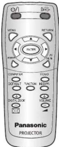 | Power cord (×1)(K2CG3YY00072) | RGB signal cable (×1) 1.8 m (5' 10")(K1HY15YY0009)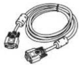 |
Power cord secure lock (×1)(TTRA0185)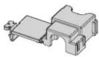 | AAA/R03 batteries for Remote control (×2) | |
Carrying bag (×1)(TPEP033)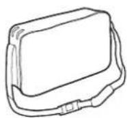 | Lens cover (×1) (TKKL5499)(Attached to the projector by default.) | CD-ROM (×1)(TXFQB02VKN5) |
NOTE:
- The protectors for the enclosed products, such as a plug cover or foam cartons, must be handled appropriately.
Contact an Authorized Service Center for any lost accessories.
Keep the accessories away from children.
- The model Nos. of the accessories and parts sold separately are subject to change without notice.
NOTE:
This product contains a CR Coin Cell Lithium Battery which contains Perchlorate Material - special handling may apply. See www.dtsc.ca.gov/hazardouswaste/perchlorate.
Start-up display
The LANGUAGE and INITIAL SETTING menu will be displayed when the projector is turned on for the first time or after it has been initialized. ( page 39)
Navigate the DISPLAY OPTION menu to set the menus in accordance to its application and environment settings.
NOTE:
- When the projector is turned on for the first time, you may be required to adjust the "zoom ring" and "focus ring" (⇒ page 11) on the top of the projector body to make the menu screen clearer.
For details, see POSITION THE IMAGE. ( page 22)
LANGUAGE
1

To select the desired language.
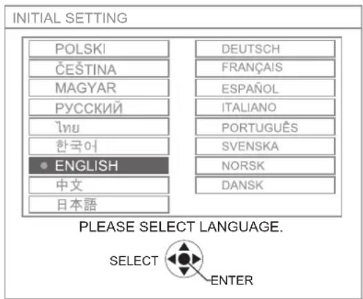
2

To proceed to INITIAL SETTING menu.
INITIAL SETTING
1

To select the desired menu.
→ INSTALLATION
→ HIGH ALTITUDE MODE
2

To change the settings in the menu.
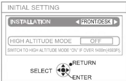
| INSTALLATION (⇔ page 15, 37) | |
| FRONT/ DESK | Put it on a desk or floor and project from the front |
| FRONT/ CEILING | Mount it on the ceiling with a ceiling mount bracket (sold separately) and project from the front |
| REAR/ DESK | Put it on a desk or floor and project from the rear (a translucent screen is required) |
| REAR/ CEILING | Mount it on the ceiling with a ceiling mount bracket (sold separately) and project from the rear (a translucent screen is required) |
| HIGH ALTITUDE MODE (⇒ page 7, 37) | |
| OFF | Use in normal environment(below 1 400 m (4 593 ft) above sea level) |
| ON Use at high altitude(at 1 400 - 2 700 m (4 593 - 8 858 ft)above sea level) | |
3

NOTE:
- To return to LANGUAGE menu, press [RETURN] in INITIAL SETTING menu.
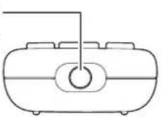
Details of your projector
PROJECTOR'S MAIN UNIT
Top and front view
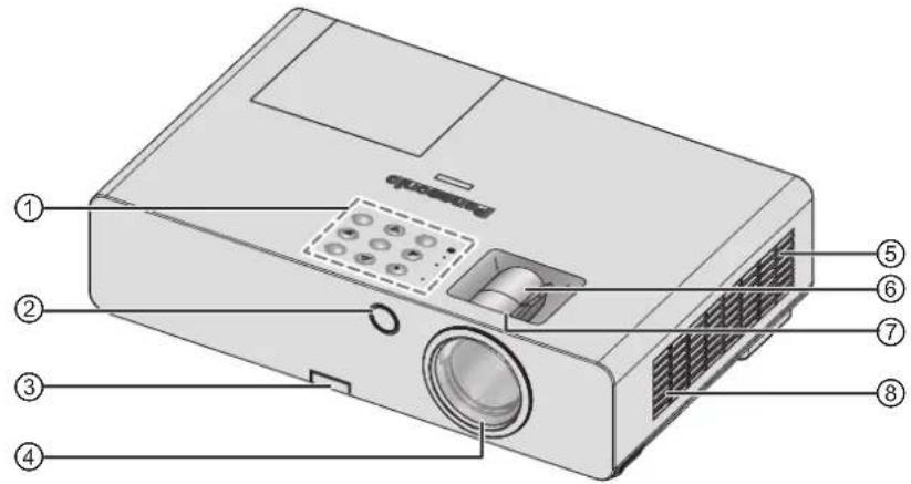
① Control Panel / Indicators
② Remote control signal receptor
③ Leg adjuster button ( page 22)
④ Projection lens
⑤ Air filter compartment (⇒ page 44)
⑥ Zoom ring – To adjust the size of projection.
(⇒ page 22)
⑦ Focus ring – To adjust the focus. (⇒ page 22)
⑧ Air intake port
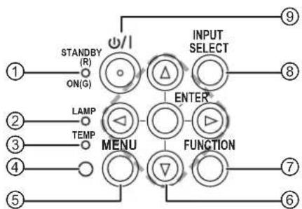
Control Panel / Indicators
flowchart
graph TD
    A["1"] --> B["STANDBY (R)"]
    B --> C["ON(G)"]
    D["2"] --> E["LAMP"]
    F["3"] --> G["TEMP"]
    H["4"] --> I["0"]
    J["5"] --> K["0"]
    L["6"] --> M["0"]
    N["7"] --> O["0"]
    P["8"] --> Q["0"]
    R["9"] --> S["0"]
    T["MENU"] --> U["△"]
    V["FUNCTION"] --> W["▽"]
    X["INPUT SELECT"] --> Y["○"]
    Z["ENTER"] --> AA["○"]
    AB["○"] --> AC["○"]
① Indicate the power supply's status. (⇒ page 19)
② Indicate the lamp unit's status. (⇒ page 43)
③ Indicate the temperature's status. (⇒ page 43)
④ Ambient Luminance sensor (ALS).
⑤ Display the Main menu.
⑥ Navigate through the menus. Confirm selection.
⑦ Create shortcut assigned to certain selected function. ( page 25, 38)
⑧ Switch the input connections.
(⇒ page 22)
⑨ Switch between standby mode and projection mode. ( page 20)
Details of your projector (continued)
Rear and bottom view
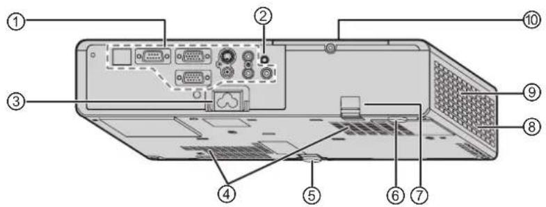
① Terminals
② Remote control signal receptor
③ AC IN
Connect the power cord to supply electric power to the projector. ( page 18)
④ Air intake port
⑤ Front leg adjuster
To adjust the projection angle. ( page 22)
⑥ Rear leg adjuster
To adjust the projection angle. ( page 22)
⑦ Burglar hook port
Attach a commercial burglar prevention cable.
⑧ Air outlet port
Hot air comes out from this opening.
⑨ Speaker
⑩ Lamp unit compartment (⇒ page 46)
NOTE:
Do not connect any power cable other than the attached one.
Do not cover the ventilation openings of the air intake port or air outlet port.
Terminals
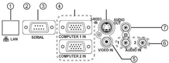
① Connect to a network cable.
(See "Network Operation Manual".)
② Connect to a computer to control the projector's operation.
(⇒ page 17, 51)
③ Connect to a computer or YP_BP_R signal cable. ( page 17)
④ Connect to an S-VIDEO signal cable.
(⇒ page 16)
⑤ Connect to a VIDEO signal cable.
(⇒ page 16)
⑥ Connect audio cables for inputting audio signal. (⇒ page 17)
⑦ Connect an audio cable for audio signal output to the connected equipment. If it is connected to this terminal, no sound comes out of the built-in speaker.
(⇒ page 16, 17)
NOTE:
- Do not place your hands or other objects close to the air outlet port as this may cause damage or injury.
- Do not place your hands or face, or objects which cannot withstand heat near the air outlet port. Hot air comes out from this port.
Details of your projector (continued)
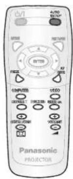
PROJECTOR'S REMOTE CONTROL
Top and rear view
Remote control signal emitters
Installing/removing batteries
Press the tab and lift up the cover.
Insert the batteries according to the polarity diagram indicated inside or remove.
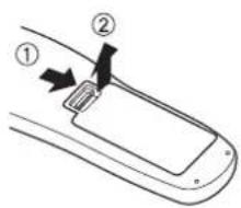
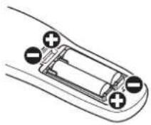
Use only manganese batteries.
Front view
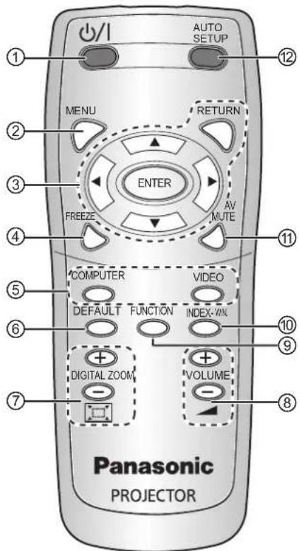
① POWER
Switch between standby mode and projection mode. ( page 20, 21)
② Display the Main menu. ( page 27)
③ Navigate through the menus with [▲▼◀▶] and confirm the selection with [ENTER]. (⇒ page 26)
④ Capture the projected image as a frozen picture. ( page 23)
⑤ Switch the required input signal button to select. ( page 23)
⑥ Reset some of the settings to the factory default settings. (⇒ page 24)
⑦ Control the zoom size. (⇒ page 25)
⑧ Control speaker volume. (⇒ page 24)
⑨ Create shortcut assigned to certain selected function. (⇒ page 25, 38)
⑩ Display frozen image while the display of subsequent images continues. (⇒ page 24)
⑪ Turn off the projection temporarily. (⇒ page 23)
⑫ Detect the input signal.
Adjust the settings of SHIFT, DOT CLOCK and CLOCK PHASE in the POSITION menu automatically for COMPUTER signals. (⇒ page 23)
NOTE:
Do not drop the remote control.
Avoid contact with liquids or moisture.
Do not attempt to modify or disassemble the remote control.
Do not let strong light shine onto the signal receptor which will cause a malfunction.
- The remote control operates within the range of 7 m (23' 0"), approximately ±30° vertically and horizontally from the projector avoiding any obstacles.
- The operating range may differ due to the screen material and may not be effective with a translucent screen.
Set up your projector
SCREEN SIZE AND THROW DISTANCE
You can adjust the projection size with 1.2 × zoom lens. Calculate and define the throw distance as follows.
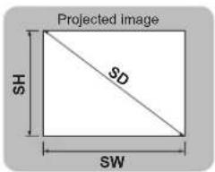
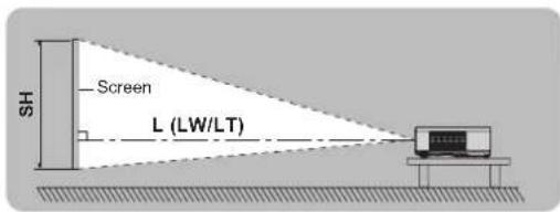
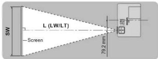
(All measurements below are approximate and may differ slightly from the actual measurements.)
| Projection size | For 4:3 aspect ratio For 16:9 aspect ratio | |||||||
| Screen diagonal (SD) | Minimum distance (LW) | Maximum distance (LT) | Minimum distance (LW) | Maximum distance (LT) | ||||
| PT-LB2 PT-LB1 PT-LB2 PT-LB1 PT-LB2 PT-LB1 PT-LB2 PT-LB1 | ||||||||
| 0.84 m (33") | — | — | 1.1 m (3' 7") | 1.1 m (3' 7") | — | — | 1.2 m (3' 11") | 1.3 m (4' 3") |
| 1.02 m (40") | 1.1 m (3' 7") | 1.2 m (3' 11") | 1.4 m (4' 7") | 1.4 m (4' 7") | 1.3 m (4' 3") | 1.3 m (4' 3") | 1.5 m (4' 11") | 1.5 m (4' 11") |
| 1.27 m (50") | 1.4 m (4' 7") | 1.5 m (4' 11") | 1.7 m (5' 6") | 1.8 m (5' 9") | 1.6 m (5' 3") | 1.6 m (5' 3") | 1.9 m (6' 2") | 1.9 m (6' 2") |
| 1.52 m (60") | 1.7 m (5' 6") | 1.8 m (5' 9") | 2.1 m (6' 10") | 2.1 m (6' 10") | 1.9 m (6' 2") | 1.9 m (6' 2") | 2.3 m (7' 6") | 2.3 m (7' 6") |
| 1.78 m (70") | 2.0 m (6' 6") | 2.1 m (6' 10") | 2.4 m (7' 10") | 2.5 m (8' 2") | 2.2 m (7' 2") | 2.3 m (7' 6") | 2.6 m (8' 6") | 2.7 m (8' 9") |
| 2.03 m (80") | 2.3 m (7' 6") | 2.4 m (7' 10") | 2.8 m (9' 2") | 2.8 m (9' 2") | 2.5 m (8' 2") | 2.6 m (8' 6") | 3.0 m (9' 10") | 3.1 m (10' 2") |
| 2.29 m (90") | 2.6 m (8' 6") | 2.7 m (8' 9") | 3.1 m (10' 2") | 3.2 m (10' 6") | 2.9 m (9' 6") | 2.9 m (9' 6") | 3.4 m (11' 1") | 3.5 m (11' 5") |
| 2.54 m (100") | 2.9 m (9' 6") | 3.0 m (9' 10") | 3.5 m (11' 5") | 3.5 m (11' 5") | 3.2 m (10' 6") | 3.3 m (10' 8") | 3.8 m (12' 5") | 3.9 m (12' 8") |
| 3.05 m (120") | 3.5 m (11' 5") | 3.6 m (11' 8") | 4.2 m (13' 9") | 4.3 m (14' 1") | 3.8 m (12' 5") | 3.9 m (12' 8") | 4.6 m (15' 1") | 4.7 m (15' 4") |
| 3.81 m (150") | 4.4 m (14' 4") | 4.5 m (14' 8") | 5.2 m (17' 0") | 5.3 m (17' 4") | 4.8 m (15' 7") | 4.9 m (16' 1") | 5.7 m (18' 8") | 5.8 m (19' 0") |
| 5.08 m (200") | 5.8 m (19' 0") | 6.0 m (19' 7") | 7.0 m (22' 11") | 7.1 m (23' 3") | 6.3 m (20' 8") | 6.6 m (21' 7") | 7.6 m (24' 11") | 7.8 m (25' 6") |
| 6.35 m (250") | 7.3 m (23' 11") | 7.5 m (24' 6") | 8.7 m (28' 6") | 8.9 m (29' 2") | 7.9 m (25' 11") | 8.2 m (26' 9") | 9.5 m (31' 2") | 9.7 m (31' 8") |
| 7.62 m (300") | 8.7 m (28' 6") | 9.0 m (29' 5") | 10.5 m (34' 5") | 10.7 m (35' 1") | 9.5 m (31' 2") | 9.9 m (32' 5") | 11.5 m (37' 7") | 11.7 m (38' 4") |
You can calculate detailed screen dimensions from the "Screen diagonal". The unit of all the calculation results is m. (The results below differ slightly from the actual measurements.)
If the projection size is SD,
| For 4:3 aspect ratio | For 16:9 aspect ratio | ||
| Screen height (SH) | = SD (") × 0.0152 | = SD (") × 0.0125 | |
| Screen width (SW) | = SD (") × 0.0203 | = SD (") × 0.0221 | |
| Minimum distance (LW) | PT-LB2 | = 0.0292 × SD (") - 0.025 | = 0.0318 × SD (") - 0.011 |
| PT-LB1 | = 0.0302 × SD (") - 0.035 | = 0.0330 × SD (") - 0.041 | |
| Maximum distance (LT) | PT-LB2 | = 0.0351 × SD (") - 0.033 | = 0.0383 × SD (") - 0.035 |
| PT-LB1 | = 0.0358 × SD (") - 0.035 | = 0.0391 × SD (") - 0.040 | |
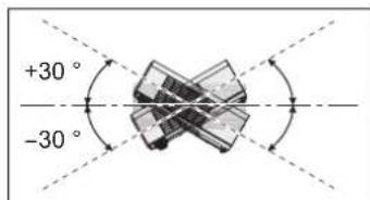
NOTE:
- For best projection image quality, install a screen where sunlight or room lightings do not shine directly onto the screen. Close window shades or curtains to block the light and turn off the lightings.
- Do not use the projector at a raised or horizontally tilted position. It may cause the projector to malfunction.
However, you can tilt the projector's body approximately ±30^ vertically and ±10^ horizontally.
Over tilting may result in shortening the component's life.
- Do not cover the air outlet port and air intake ports or place anything within 50 cm (20") near them as this may cause damage or injury.
Set up your projector (continued)
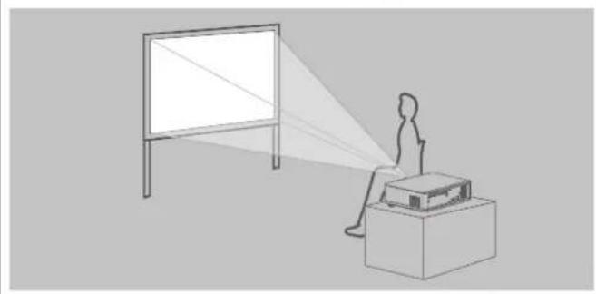
PROJECTION METHOD
See "INSTALLATION" on page 37 to select the projection method.
■ Put it on a desk or floor and project from the front
natural_image
Line drawing of a person sitting at a desk watching a projector screen (no text or symbols)| Menu Method |
| INSTALLATION FRONT/DESK |
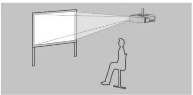
■ Mount it on the ceiling and project from the front
natural_image
Line drawing of a person seated facing a projector screen, with no text or symbols present.| Menu Method |
| INSTALLATION FRONT/CEILING |
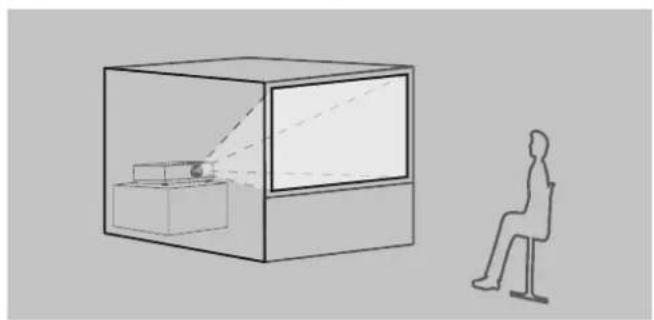
Put it on a desk or floor and project from the rear (Use translucent screen)
natural_image
Simple line drawing of a person sitting in front of a transparent display case, with no text or symbols present.| Menu Method |
| INSTALLATION REAR/DESK |
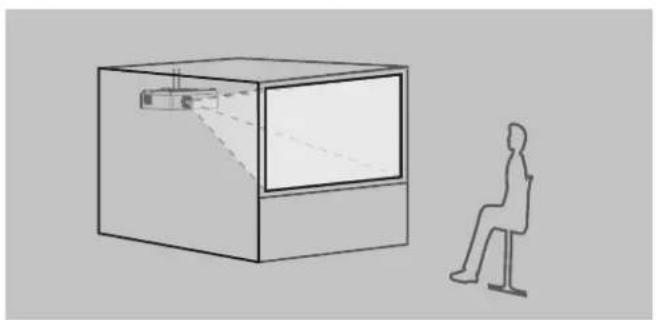
Mount it on the ceiling and project from the rear ■ (Use translucent screen)
natural_image
Simple line drawing of a person sitting in a chair next to a rectangular display case with a small screen and projection lines (no text or symbols)| Menu Method | |
| INSTALLATION REAR/CEILING |
NOTE:
Use the optional ceiling mount bracket (ET-PKB2) when mounting the projector on the ceiling.
- You can adjust the projection angle in the vertical direction by adjusting the leg adjuster button. (⇒ page 22)
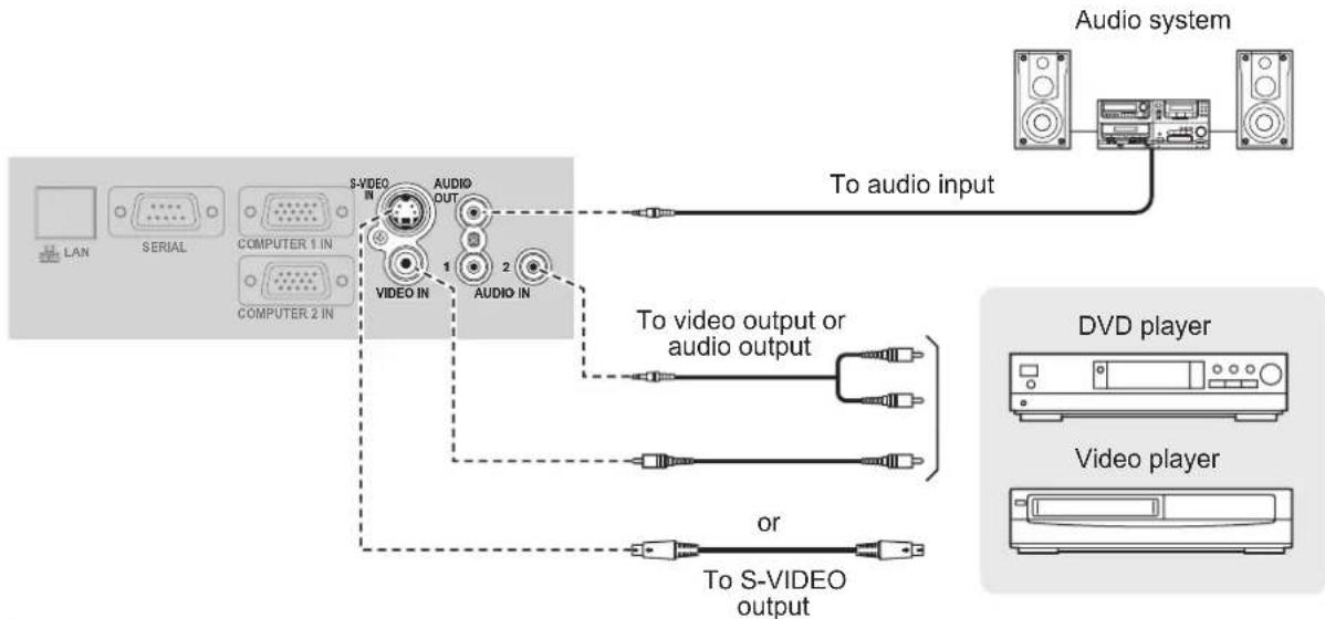
Connections
Preparations
- Read and follow the operating instructions of each peripheral device and turn the peripheral devices off prior to making any connections.
- Prepare the selected peripheral devices with the connection cables that correspond to the projector's terminals.
- All peripheral devices and cables used for the connections are sold separately unless indicated otherwise.
- If the input signal is affected by signal jitter, the projected image may have poor image quality and timebase correction is effective.
Confirm the types of video signals, • see "LIST OF COMPATIBLE SIGNALS" (page 50)
Example: AV equipment
flowchart
graph TD
    A["LAN"] --> B["S-VIDEO IN"]
    C["SERIAL"] --> B
    D["COMPUTER 1 IN"] --> B
    E["COMPUTER 2 IN"] --> B
    B --> F["VIDEO IN"]
    B --> G["AUDIO OUT"]
    G --> H["1"]
    G --> I["2"]
    H --> J["To audio input"]
    I --> K["To video output or audio output"]
    L["Video player"] --> M["DVd player"]
    N["Video player"] --> O["DVd player"]
    P["To S-VIDEO output"] --> Q["or"]
NOTE:
Switch the audio connection manually for more than one AV equipment connections.
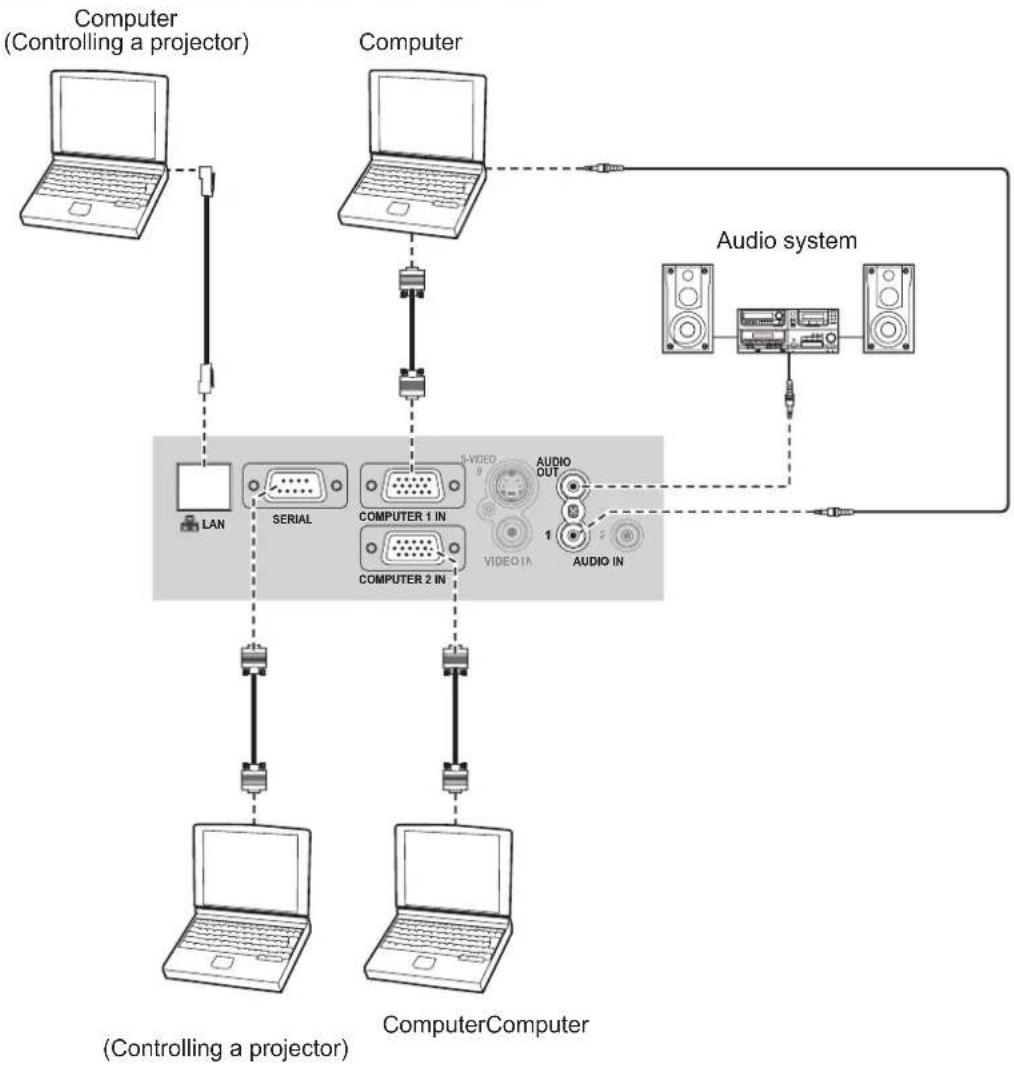
Connections (continued)
Example: Computers
flowchart
graph TD
    A["Computer (Controlling a projector)"] --> B["Computer"]
    B --> C["Audio system"]
    C --> D["Computer"]
    D --> E["Computer Computer"]
    subgraph Control
        F["LAN"] --> G["SERIAL"]
        G --> H["COMPUTER 1 IN"]
        H --> I["COMPUTER 2 IN"]
        I --> J["Computer"]
    end
    subgraph Audio
        K["1"] --> L["AUDIO OUT"]
        M["2"] --> N["AUDIO IN"]
    end
    F -.-> G
    G -.-> H
    H -.-> I
    I -.-> J
    J -.-> K
    style Control fill:#f9f,stroke:#333
    style Audio fill:#ccf,stroke:#333
NOTE:
When connecting the RGB signal cable, tighten the fixing screws on the D-Sub (15-pin) connector.
- For the network connection between the projector and computers, see "Network Operation Manual" in the CD-ROM provided.
- Only the RGB signal cable (1 piece) is attached. If any other cables are necessary, purchase them from the market.
Turn the projector ON or OFF
POWER CORD
Fix the provided "power cord secure lock" to the power cord on the projector to prevent the cord from coming off.
For details, see "Precautions with regard to safety". (⇒ pages 5 to 9)
Install the "power cord secure lock" Detach the "power cord secure lock"
1 Push the connector all the way into the AC IN terminal ensuring that the shape of the connector matches that of the terminal.
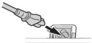
natural_image
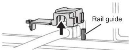
Illustration of a hand inserting a plug into a small electronic component (no text or symbols)2 Align the side of the "power cord secure lock" with the side of the "Rail guide" of the AC IN terminal and slide it in.
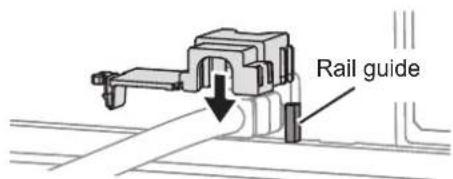
3 Latch to the latch catcher and press until it clicks.
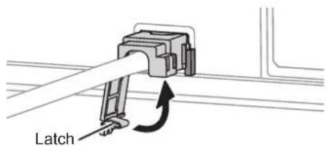
4 Connect the power plug to a wall outlet.
1 Unplug the power plug from the wall outlet.
2 Depress the latch and slide off the lock.
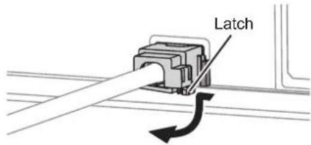
3 Slide up the "power cord secure lock" and remove it.
4 Hold the connector firmly and detach it from the AC IN terminal.
Direct power on function
If the power cord is connected to a wall outlet with INITIAL START UP (PROJECTOR SETUP menu) is set to ON, projection will start even when the control panel is disabled. (⇒ page 37)
Direct power off function
You can switch off the electric power supply any time by unplugging the power plug from the wall outlet or by switching off the main power.
The internal cooling fan keeps operating using the internal power supply and automatically stops when cooled.
NOTE:
Do not put the projector into the carrying bag with the POWER indicator lit.
Turn the projector ON or OFF (continued)
POWER INDICATOR
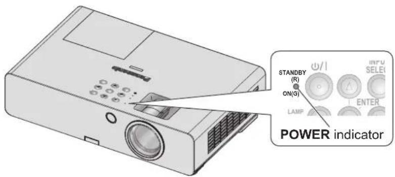
POWER indicator
→ shows status of the projector's power When the TEMP indicator flashes, the POWER indicator lights red and you cannot turn the projector on.
POWER indicator status
| Indicator status Status | ||
| No illumination or flashing No power | is supplied and the internal cooling fan is not operating. | |
| Red | Lit | The power is turned off (when STANDBY MODE is set to ECO).If [POWER] button is pressed, projection starts. |
| Flashing The power is turned off (when STANDBY MODE is set to NORMAL).If [POWER] button is pressed, projection starts. | ||
| Green | Flashing The power is on and preparing for projection. | |
| Lit The projector is projecting. | ||
| Orange | Lit No power supply and the power is preparing for being turned off.It is turned off (The projection is set in STANDBY MODE) after a while. | |
| Flashing The power is switched on again while cooling the lamp and recovering to the projection mode. Recovery may take a while. | ||
NOTE:
When the power is turned off, the internal fan cools the lamp using internal power supply.
• The power is turned on again while cooling the lamp and recovers to the projection mode. Recovery may take a while.
- While the power is turned off (when STANDBY MODE is set to ECO, the POWER indicator is lit red), power of about 0.4 W is consumed.
Turn the projector ON or OFF (continued)
TURN THE PROJECTOR ON
Before switching on the projector, make sure all the other devices are correctly connected and remove the Lens cover. ( page 16)
1 Connect the power cord. ( page 18)
After a while the “power indicator” lights or flashes in red.
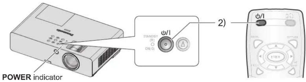
2 Press the POWER button.
POWER• indicator flashes green several times before it lights up and the STARTUP LOGO is displayed. See STARTUP LOGO in DISPLAY OPTION menu. (⇒ page 34)
NOTE:
Confirm that • CONTROL PANEL (when operating with the projector body) or REMOTE CONTROLLER (when operating with the remote control) under CONTROL DEVICE SETUP in the SECURITY menu is set to ENABLE. (⇒ page 42)
When setting the SECURITY menu, you will be asked to input the password. (⇒ page 40)
When starting up the projector, some small rattling or • tinkling sound may be heard. These are normal and will not affect the performance of the projector.
When the internal cooling fan is operating, some operational sound may be heard. The loudness of the operational sound depends on the external temperature.
- If INITIAL START UP (PROJECTOR SETUP menu) is set to ON, the projector starts projecting when the power cord is connected to a wall outlet. (⇒ page 37) If the projector is turned on again while the internal cooling fan is still operating by the internal power supply, the display may flicker due to the specifications of the lamp. These are normal and will not affect the performance of the projector.
Turn the projector ON or OFF (continued)
TURN THE PROJECTOR OFF
When operating the projector, check the status of the POWER indicator. ( page 19)
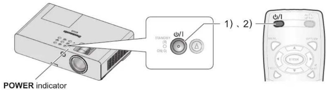
1 Press the POWER button.
A confirmation screen will be displayed – the screen will go off and return to projection if there is no operation for approximately 10 seconds.
2 Press the button again.
The lamp goes off and the projection stops.
The cooling fan continues its rotation and • POWER indicator lights orange. Wait until the POWER indicator turns red.
- If STANDBY MODE is set to NORMAL, the POWER indicator flashes red. (⇒ page 37)
3 Disconnect the power plug from the wall outlet after the POWER indicator turns red.
(⇒ page 19)
For urgency, you may disconnect the power • plug immediately since the DIRECT POWER OFF function is installed.
NOTE:
Confirm that • CONTROL PANEL (when operating with the projector body) or REMOTE CONTROLLER (when operating with the remote control) under CONTROL DEVICE SETUP in the SECURITY menu is set to ENABLE. (⇒ page 42)
- Power can be turned off by pressing [POWER] for at least 0.5 seconds.
Project an image
Preparations
Confirm the connections of the peripheral devices • (⇒ page 16, 17) and power cord (⇒ page 18).
Switch on the power •( page 20) to start projecting.
Select the input signal and adjust the image.
SELECT THE INPUT SIGNAL
1 Switch on the connected devices.
When playing a connected DVD player, if SIGNAL SEARCH (DISPLAY OPTION menu) is set to ON, the input signal is detected and projected automatically when the projector is switched on. (⇒ page 35)
Set the • INPUT GUIDE (DISPLAY OPTION) ON-SCREEN DISPLAY menu) to DETAILED. If the projector cannot detect any input signal, the "Computer connection guide" will be displayed. (⇒ page 33)
2 Select an input signal.
The image selected with any of the [INPUT SELECT] button is projected.
NOTE:
- Change the settings in the PICTURE menu according to the connected device for example DVD, video tape, etc., to be played. (⇒ page 28)
Confirm the aspect ratio of the screen and image.
Select the optimum aspect ratio. ( page 31)
POSITION THE IMAGE
When setting up the projector for the first time or setting up at a new place, you must perform the following operations.
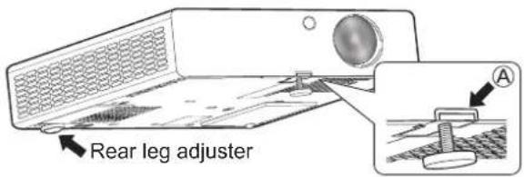
1 Adjust the vertical angle of the projector.
Place the projector at the right angle from the screen.

natural_image
Simple line drawing of a vertical pole with a horizontal dashed line and a rectangular box with icons on the right side (no text or symbols)Press the leg adjuster button Ⓐ and adjust the vertical projection angle. Then, adjust the projected image to the center of the screen.
2 Adjust the projection size and focus.
Turn the zoom and focus rings to adjust the projected image.
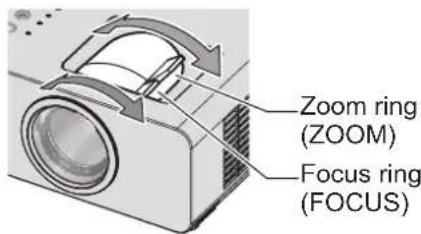
NOTE:
When you adjust the zoom after adjusting the focus, you may need to adjust the focus of the image again.
- If the projected image slants to the right or left, turn the rear leg adjuster to adjust the angle of the projector.
- If keystone distortion occurs, see KEYSTONE. ( page 30)
Remote control operation
CAPTURE AN IMAGE
You can freeze the projected image and temporarily stop the sound, regardless of the playing condition of the connected device.
FREEZE

Press the button again to cancel it. The image is distorted momentarily when the projection is stopped and restarted.
STOP THE PROJECTION TEMPORARILY
You can temporarily stop the projection and the sound from the projector.

Press the button again to cancel it.
SWITCH THE INPUT SIGNAL
You can switch the input signal to be projected.
COMPUTER
COMPUTER

The options below are displayed each time you press this button.
| COMPUTER1 | Signal input to COMPUTER1 IN terminal |
| COMPUTER2 | Signal input to COMPUTER2 IN terminal |
VIDEO
VIDEO

The options below are displayed each time you press this button.
| S-VIDEO Signal input to S-VIDEO IN terminal |
| VIDEO Signal input to VIDEO IN terminal |
You can confirm the selected input terminal (from the graphical input terminal guide on the upper right of the screen), if INPUT GUIDE (DISPLAY OPTION → ON-SCREEN DISPLAY menu) is set to DETAILED. (⇒ page 33)
You can change the input with [▲▼◄►]. It may take some time to change the image after the input signal is switched.
NOTE:
Input a compatible signal shown in the "LIST OF COMPATIBLE SIGNALS". (⇒ page 50)
For the input terminals, • see "Connections" = (page 16) The input guide automatically disappears when it is left • idle.
Press [INPUT SELECT] on the control panel to switch the input in the following order. ( page 11)
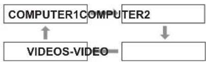
flowchart
graph TD
    A["COMPUTER1"] --> B["COMPUTER2"]
    B --> C["VIDEOS-VIDEO"]
    C --> A
SET UP THE IMAGE POSITION AUTOMATICALLY
The projector automatically adjusts the SHIFT, DOT CLOCK and CLOCK PHASE when an RGB signal is input.
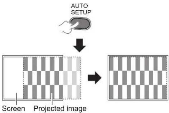
flowchart
graph TD
    A["AUTO SETUP"] --> B["Projected image"]
    B --> C["Screen"]
NOTE:
- The SIGNAL SEARCH will be in operation when it is set to ON. (⇒ page 35)
If the dot clock frequency is higher than 162 MHz, DOT CLOCK and CLOCK PHASE can not be adjusted automatically. (⇒ page 30, 31) - If the projected signal or image is too dark or blurred around the edge, AUTO SETUP may stop the process before completing the adjustment or adjust abnormally. Project a much clearer or lighter image and try again.
Remote control operation (continued)
RESET TO FACTORY DEFAULT SETTINGS
You can reset most of the customized settings to the factory default settings.
DEFAULT

For details, see "Reset to factory default settings". (⇒ page 26)
CONTROL SPEAKER VOLUME
You can control the volume of the built-in speakers and output audio sound.

- : increases the volume
- : decreases the volume
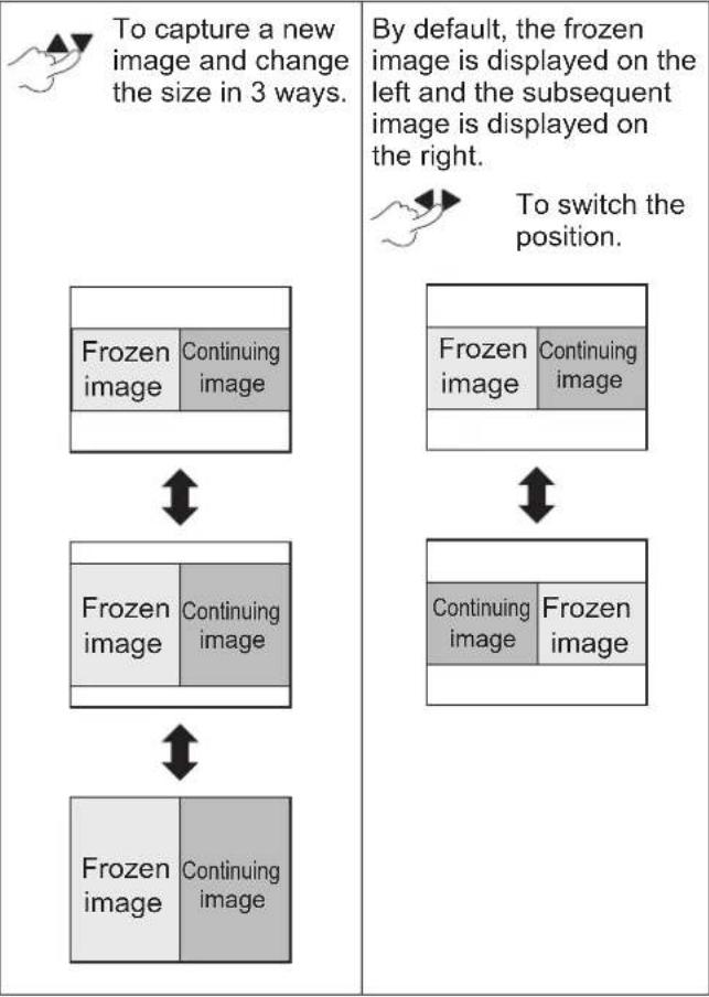
PROJECT AN IMAGE USING INDEX-WINDOW
You can split a projected image into 2 windows using INDEX-WINDOW. One frozen image is stored in memory and displayed on the left side of the screen. Projection continues for the other image on the right side.
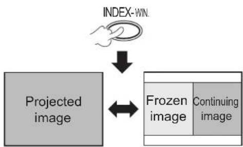
flowchart
graph TD
    A["INDEX-WIN"] --> B["Projected image"]
    B <--> C["Frozen image"]
    C --> D["Continuing image"]
Press [RETURN] to escape.
INDEX-WINDOW display
flowchart
graph TD
    A["To capture a new image and change the size in 3 ways."] --> B["Frozen image"]
    A --> C["Continuing image"]
    B --> D["Frozen image"]
    B --> E["Continuing image"]
    C --> F["Frozen image"]
    C --> G["Continuing image"]
    D --> H["Frozen image"]
    E --> I["Frozen image"]
    F --> J["Frozen image"]
    G --> K["Frozen image"]
    style A fill:#f9f,stroke:#333
    style B fill:#ccf,stroke:#333
    style C fill:#ccf,stroke:#333
    style D fill:#cfc,stroke:#333
    style E fill:#cfc,stroke:#333
    style F fill:#cfc,stroke:#333
    style G fill:#cfc,stroke:#333
    style H fill:#fcc,stroke:#333
    style I fill:#fcc,stroke:#333
    style J fill:#fcc,stroke:#333
    style K fill:#fcc,stroke:#333
NOTE:
The aspect ratio of the image is changed and becomes • vertically elongated.
If you change the window size, the aspect ratio of the image is changed. ( page 31)
- While in INDEX-WINDOW mode, press [ENTER] to capture a new image and the frozen image's window will be updated.
When capturing a quick moving picture, repeat several times to get a stable picture.
Remote control operation (continued)
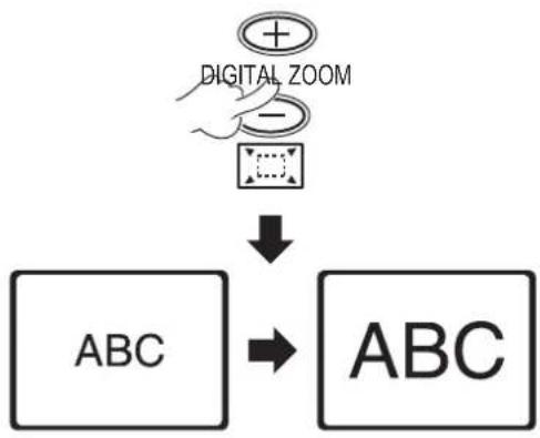
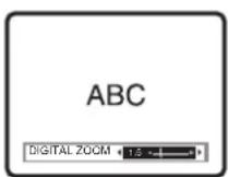
ENLARGE THE IMAGE
You can enlarge the projected image to the center position by emphasizing within the range of 1× to 2×.
flowchart
graph TD
    A["Digital Zoom"] --> B["ABC"]
    B --> C["ABC"]
Press [RETURN] or [MENU] to escape.
[DIGITAL ZOOM] button operation
![PANASONIC PTLB2U - [DIGITAL ZOOM] button operation - 1](/content/2026/03/515987/images/c557cdb2d545ee6bf3cfa12386e4a5080c870687d8dc3a85c63d69c3aa23a131.jpg)
flowchart
graph LR
    A["+ button: zooms in"] --> B["Press “-” (STANDARD)"]
    C["- button: zooms out"] --> B
    B --> D["Press “+” (MAXIMUM)"]
    E["ABC"] <--> F["ABC"]
    F <--> G["ABC"]
![PANASONIC PTLB2U - [DIGITAL ZOOM] button operation - 2](/content/2026/03/515987/images/ae98de697dd5ebac703ae571840e611f4a307d285bb93fed36fbb15a9ad4dcc0.jpg)
flowchart
graph TD
    A["ABC"] --> B["BC"]
    B --> C["ABC"]
    C --> D["AB"]
    D --> E["ABC"]
    style A fill:#fff,stroke:#000
    style B fill:#fff,stroke:#000
    style C fill:#fff,stroke:#000
    style D fill:#fff,stroke:#000
    note right of A: "Press '▲▼◀▶' to shift the center point."
    note right of D: "(Operation during zoom mode)"
NOTE:
- When the COMPUTER signal is input, if FRAME LOCK in the POSITION menu is OFF,
→ enlargement range is 1× to 3×. - When the COMPUTER signal is input, if FRAME LOCK in the POSITION menu is ON,
→ enlargement range is 1× to 2×.
When another signal is input, the enlargement range is from 1 × to 2 × by 0.1.
DIGITAL ZOOM• mode is canceled when the input signal is changed. - During DIGITAL ZOOM mode, [AUTO SETUP], [FREEZE], [DEFAULT], [INDEX-WINDOW] and [FUNCTION] (except when AV MUTE is assigned) buttons are not available.
The image is distorted momentarily when the image is • zoomed.
USE AN ASSIGNED FUNCTION
You can select a useful function from the list and assign it to [FUNCTION] button as a shortcut.

To display the on-screen menu (main menu, sub-menu or detailed menu).
For the menu operation, see "OPERATE THE MENU". (⇒ page 26)
Press and hold for at least 3 seconds.
When not using the [FUNCTION] button
1 Select DISABLE in FUNCTION BUTTON (PROJECTOR SETUP menu).
2 Press [ENTER].
3 Select OK.
4 Press [ENTER].
NOTE:
For details, • see FUNCTION BUTTON in PROJECTOR SETUP menu. (⇒ page 38)
Menu operation
OPERATE THE MENU
Depending on the selected input signals, some items and functions may not be adjusted or available. Some can be adjusted without any signals.
1
2 Select the main menu item.
3 Select the sub-menu item.
4

Press ▲▼ buttons to scroll to the required sub-menu item and press ◀▶ buttons or the ENTER button to adjust.
The selected menu is called up while other menu item disappears from the screen.
NOTE:
- Press [MENU] or [RETURN] to return to the previous menu. Press repeatedly to exit from the menu mode and return to the projection.
Called up item will disappear after 5 seconds without any operation and return to the menu mode.
For the sub-menu items, • see "SUB MENU" in the ON-SCREEN MENU (⇒ page 27).
Reset to factory default settings
DEFAULT
During sub-menu screen display: The items of the sub-menu currently displayed are reset to the factory default settings.
During called up item screen display: Only the item adjusted currently is reset to the factory default setting.
NOTE:
You cannot reset all the settings at one time to the factory • default settings.
For resetting all the settings, • see INITIALIZE ALL (PROJECTOR SETUP menu). (⇒ page 39)
- Not all menu items can be reset by pressing [DEFAULT]. Adjust each menu item manually.
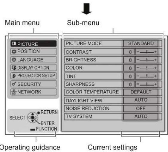
ON-SCREEN MENU
You can access other functions from operating this menu by referring to "OPERATE THE MENU". ( see left)
MENU
The ON-SCREEN MENU displayed consists of the main menu and sub-menu.
Menu operation (continued)
MAIN MENU

flowchart
graph LR
    A["MENU"] --> B["Main menu"]
    B --> C["ENTER"]
    C --> D["Sub-menu"]
 | PICTURE |
 | POSITION |
 | LANGUAGE |
 | DISPLAY OPTION |
 | PROJECTOR SETUP |
 | SECURITY |
 | NETWORK |
SUB MENU
Select the required sub-menu item and press ENTER to display the detailed menu.
PICTURE menu
S-VIDEO/VIDEO/RGB (Moving image) ^*1 / YPBPR signal is input.
| Sub-menu item Default Page | ||
| PICTURE MODE STANDARD 28 | ||
| CONTRAST 0 28 | ||
| BRIGHTNESS 0 28 | ||
| COLOR 0 29 | ||
| TINT 0 29 | ||
| SHARPNESS 0 29 | ||
| COLOR TEMPERATURE DEFAULT 29 | ||
| DAYLIGHT VIEW AUTO 29 | ||
| NOISE REDUCTION*2 | OFF 29 | |
| TV-SYSTEM*2 | AUTO 29 | |
| RGB/YPBR*3 | AUTO 30 | |
*1 RGB moving images can be projected only when the following signals:
480i, 576i, 480p, 576p, 1 080/60i,
1 080/50i, 720/60p, 720/50p
*2 Input signal is S-VIDEO/VIDEO.
*3 Input signal is RGB/YP B P R .
RGB (Still image) is input.
| Sub-menu item Default | Page | |
| PICTURE MODE | DYNAMIC | 28 |
| CONTRAST | 0 | 28 |
| BRIGHTNESS | 0 | 28 |
| SHARPNESS | 0 | 29 |
| WHITE BALANCE RED*1 | 0 | 29 |
| WHITE BALANCE GREEN*1 | 0 | 29 |
| WHITE BALANCE BLUE*1 | 0 | 29 |
| COLOR TEMPERATURE | DEFAULT | 29 |
| DAYLIGHT VIEW | AUTO | 29 |
| RGB/YPBPR*2 | AUTO | 30 |
*1 Input signal is RGB.
^*2 Input signal is RGB (VGA60).
NOTE:
- The factory default values vary depending on the PICTURE MODE setting.
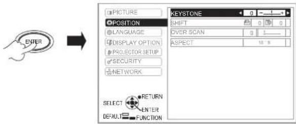
POSITION menu
| Sub-menu item Default | Page | |
| REALTIME KEYSTONE | ON | 30 |
| KEYSTONE | 0 30 | |
| SHIFT*1 | 0 | 30 |
| DOT CLOCK*1 | 0 | 30 |
| CLOCK PHASE*1 | 0 | 31 |
| OVER SCAN*1 | 0 | 31 |
| ASPECT*1 | 16:9 31 | |
| FRAME LOCK*1 | OFF 32 |
*1 The setting is activated or deactivated depending on the input signal and the specific setting.
LANGUAGE menu
For details, see "LANGUAGE MENU". (⇒page 33)
DISPLAY OPTION menu
| Sub-menu item Default | Page | |
| ON-SCREEN DISPLAY | — | 33 |
| CLOSED CAPTION SETTING | OFF | 34 |
| STARTUP LOGO | ON | 34 |
| AUTO SETUP | AUTO | 35 |
| SIGNAL SEARCH | ON | 35 |
| BACK COLOR | BLUE | 35 |
| WIDE MODE*1 | AUTO | 36 |
| SXGA MODE*1 | SXGA | 36 |
| OTHER FUNCTIONS | — | 36 |
*1 The setting is activated or deactivated depending on the input signal and the specific setting.
Menu operation (continued)
PROJECTOR SETUP menu
| Sub-menu item Default Page | ||
| STATUS — 36 | ||
| NO SIGNAL SHUT-OFF DISABLE 37 | ||
| INITIAL START UP LAST MEMORY 37 | ||
| INSTALLATION FRONT/DESK 37 | ||
| HIGH ALTITUDE MODE OFF 37 | ||
| STANDBY MODE ECO 37 | ||
| LAMP POWER NORMAL 37 | ||
| LAMP RUNTIME | — 38 | |
| EMULATE | DEFAULT | 38 |
| FUNCTION BUTTON | STATUS | 38 |
| AUDIO SETTING | — 38 | |
| TEST PATTERN | — 39 | |
| INITIALIZE ALL | — 39 | |
SECURITY menu
| Sub-menu item Default | Page | |
| PASSWORD | OFF | 40 |
| PASSWORD CHANGE | — | 40 |
| TEXT DISPLAY | OFF | 40 |
| TEXT CHANGE | — | 40 |
| MENU LOCK | OFF | 41 |
| MENU LOCK PASSWORD | — | 41 |
| CONTROL DEVICE SETUP | — | 42 |
NETWORK menu
For details of items, see "Network Operation Manual".
| Sub-menu item | Default |
| WIRED LAN | — |
| NAME CHANGE | — |
| NETWORK CONTROL | ON |
| STATUS | — |
| INITIALIZE | — |
NOTE:
- Sub-menu items and the factory default settings vary according to the selected input signal.
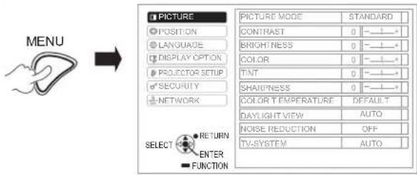
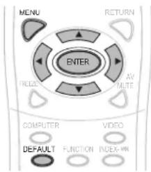
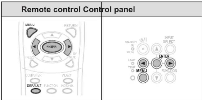
PICTURE MENU
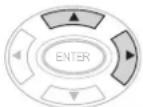
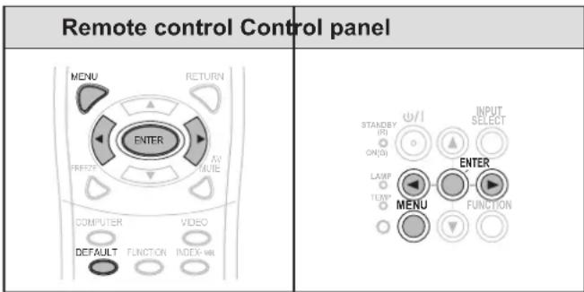
| Remote control Control panel | |
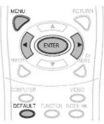 |  |
Set the selected item with [◀▶].
PICTURE MODE
You can optimize the projected image depending on the projection's environment.
Change setting

Change setting
| STANDARD | Setting for general image |
| DYNAMIC | Setting for brightness and sharpness |
| BLACKBOARD | Setting for when projecting on a blackboard |
| WHITE BOARD | Setting for when projecting on a white board |
| NATURAL | Reproducing the original color of the image |
NOTE:
- It may take a while until the selected mode is stabilized.
CONTRAST
You can adjust the contrast of the projected image.

BRIGHTNESS
You can adjust the brightness of the projected image.

Menu operation (continued)
COLOR
You can adjust the color saturation of the projected image. (For S-VIDEO/VIDEO/RGB (Moving image)/YPBPR input signal only)

TNT
You can adjust the skin tone of the projected image. (For S-VIDEO/VIDEO/RGB (Moving image)/YPBPR input signal only)

SHARPNESS
You can adjust the sharpness of the projected image.

NOTE:
The adjustable range depends on the input signal.
WHITE BALANCE
You can adjust the white balance in 3-color temperature. (For RGB (Still image) input signal only)


| Advanced menu item Default | |
| WHITE BALANCE RED 0 | |
| WHITE BALANCE GREEN 0 | |
| WHITE BALANCE BLUE 0 | |
COLOR TEMPERATURE
You can adjust the white balance of the projected image.

| DEFAULT Balanced white |
| HIGH More bluish |
| LOW More reddish |
DAYLIGHT VIEW
You can keep the projected image bright and vivid even in well-lit rooms where the ambient light sources cannot be controlled.

| AUTO Automatic adjustment | |
| ON Active | |
| OFF Deactive |
NOTE:
Do not cover the Ambient Luminance Sensor(ALS) of the projector, otherwise the AUTO mode may not function properly.
- AUTO is not available when INSTALLATION in PROJECTOR SETUP menu is set to REAR/DESK or REAR/CEILING.
NOISE REDUCTION
You can switch the automatic noise reduction system on/off. (For S-VIDEO/VIDEO input signal only)

| OFF No noise reduction |
| ON Automatic noise reduction |
NOTE:
- If NOISE REDUCTION is set active when the selected input signal has less noise, the image may look different from the true image. If so, set to OFF.
TV-SYSTEM
Switch the setting manually to match the video data. (For S-VIDEO/VIDEO input signal only)

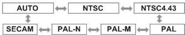
flowchart
graph TD
    A["AUTO"] <--> B["NTSC"]
    B <--> C["NTSC4.43"]
    C <--> D["PAL"]
    D <--> E["PAL-M"]
    E <--> F["PAL"]
    F <--> G["SECAM"]
    G <--> H["PAL-N"]
NOTE:
- AUTO mode is selected by default.
- When the projector is not working properly in AUTO mode, change the setting according to each TV system type.
- AUTO setting will automatically select the compatible signal from NTSC/NTSC 4.43/PAL/PAL60/PAL-M/PAL-N/SECAM.
Menu operation (continued)
RGB/YPBPR
(For RGB/YP _B PR input signal only)
Select the signals to be input to the COMPUTER 1 IN and COMPUTER 2 IN terminals.
Change setting
Change setting
| AUTO Automatic adjustment | |
| RGB For | RGB signals |
| YP_BP_R | For YP_BP_R signals |
NOTE:
AUTO• mode is selected by default.
Select • RGB or YBPR according to the input signal if the image is not normally projected during AUTO mode.
The function only becomes effective when certain signals are input:
(VGA60, 480i, 576i, 480p, 576p, 1 080/60i, 1 080/50i, 720/60p, 720/50p)
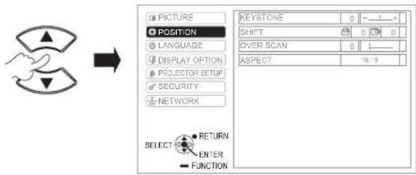
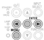
POSITION MENU
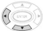
Remote control Control panel
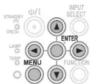
Set the selected item with [▲▼◀▶].
REALTIME KEYSTONE
If the projector is aligned non-perpendicularly to the screen, or if the projection screen has an angled surface; the keystone will be automatically corrected.
Change setting

Change setting
| OFF Deactive |
| ON Active |
NOTE:
If the detected tilt of the main unit is ± 5% , even if you set ON, the distortion will not be corrected automatically. Because the priority is not to correct the distortion, but to avoid the image quality deteriorated by correcting.
If you need to correct the keystone, you can correct the • distortion manually by adjusting the KEYSTONE.
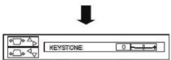
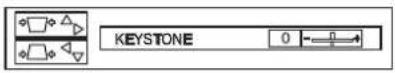
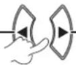
HEYSTONE
If you need to correct the angle of the projection even when the REALTIME KEYSTONE is activated, you can correct the keystone manually.
| Image Operation | |
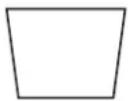 |  |
 |  |
NOTE:
You can correct the distortion ±30^ from the plane.
- For a better image quality, install the projector to minimize distortion.
- The result of the keystone correction will affect the aspect ratio and the size of the image.
- The image is distorted momentarily when the keystone is corrected.
SHIFT
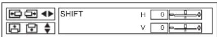
Horizontal (H): Press [◀▶] to move the image horizontally.
Vertical (V): Press [▲▼] to move the image vertically.
NOTE:
- This function can be adjusted by pressing the ◀▶▲▼ buttons directly.
NOT CLOCK
If there are interference patterns on the projected image (referred as moire or noise), minimize it by pressing [◀▶] to adjust the clock frequency. (For RGB (Still image) input signal only)

natural_image
Abstract pattern of vertical black and white stripes on white background (no text or symbols)NOTE:
- DOT CLOCK needs to be adjusted before adjusting the CLOCK PHASE.
Menu operation (continued)
QLOCK PHASE
If you require further adjustment for the same reason as the DOT CLOCK adjustment, you can further adjust the timing of the clock. (For RGB/YP _B PR input signal only) Press ◀▶ buttons to adjust.
NOTE:
If the projecting signal's dot clock frequency is higher than 162 MHz, adjusting DOT CLOCK or CLOCK PHASE may not make any difference. Refer to "LIST OF COMPATIBLE SIGNALS". (⇒ page 50)
QVER SCAN
Use this function when characters or pictures are cropped near the periphery of the projected image. (For S-VIDEO/VIDEO/RGB (Moving image)/YP _B PR input signal only)

Setting range: 0 to +3
ASPECT
You can manually switch to the desired aspect ratio. Selectable options vary according to input signal.
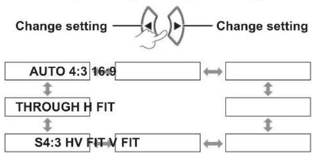
flowchart
graph TD
    A["Change setting"] --> B["AUTO 4:3 16:9"]
    B --> C["THROUGH H FIT"]
    C --> D["S4:3 HV FIT V FIT"]
    D --> E["Change setting"]
NOTE:
AUTO• mode is displayed only when NTSC/480i signal is input.
THROUGH• mode is displayed only for certain signals. For the wide signal ^*2 , the aspect ratio option cycles through 16:9 V FIT HV FIT.
AUTO (For NTSC/480i input signal only)
The signal which contains an identifying signal will be detected and will automatically project the image in the most optimal aspect setting.
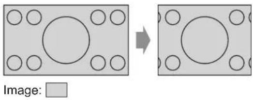
4:3
Standard input signal ^*1 → projection is 4:3 aspect ratio.
Input signal: XGA
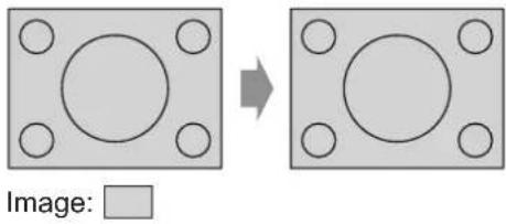
natural_image
Two identical gray square panels with circular holes, one rotated to show a larger circle (no text or symbols)16:9
Standard input signal ^1 → projection is 16:9 aspect ratio. Wide input signal ^2 → projection is the current aspect ratio.
Input signal: 1 080/60i
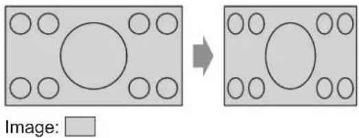
H FIT
Standard input signal*1 → projection without changing the aspect ratio uses all the panel pixels in the horizontal direction to crop the top and bottom of the image.
Input signal: SXGA
natural_image
Two identical square panels with circular holes, one rotated to show a larger circle (no text or symbols)*1 A standard signal has an aspect ratio of 4:3 or 5:4.
*2 A wide signal has an aspect ratio of 16:10, 16:9 or 15:9.
Menu operation (continued)
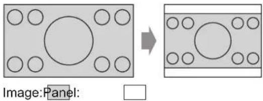
V FIT
Wide input signal*2 → projection without changing the aspect ratio uses all the panel pixels in the vertical direction to crop the right and left of the image.
Input signal: 1 080/60i
natural_image
Diagram showing two rectangular blocks with circular holes, one rotated to form a larger square (no text or symbols)HV FIT
The image is projected all over the panel pixels (screen). The input signal is projected at the aspect ratio of the panel screen.
Input signal: 1 080/60i
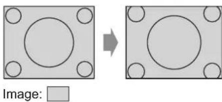
S4:3
Standard input signal*1 → the input signal will be sized down 75% and projected. S4:3 mode is effective when projecting 4:3 image onto a 16:9 screen.
Input signal: XGA
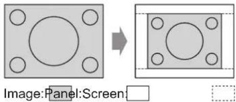
natural_image
Diagram showing a square panel with circular holes and an arrow pointing to a rectangular panel with holes (no text or symbols)*1 A standard signal has an aspect ratio of 4:3 or 5:4.
^*2 A wide signal has an aspect ratio of 16:10, 16:9 or 15:9.
THROUGH
The image will be projected without any size adjustment.
This function can be set when the input signal is smaller than the number of the LCD panel pixels (1024 x 768).
Input signal: NTSC

NOTE:
When a 4:3 image is projected to 16:9 screen, the image may be distorted or some portions may be cropped. Select an aspect ratio (4:3) which retains the creator's intended image.
The order of • ASPECT types is defined not only by the input method but also by the input signals.
If you project an enlarged or distorted copyrighted image using the ASPECT function for commercial use in a public place, you might infringe the copyright of the creator which is protected by the copyright law.
FRAME LOCK
If the projected image is bad, you can activate FRAME LOCK for synchronization. (For RGB input signal only)

| ON Active |
| OFF Deactive |
Menu operation (continued)
LANGUAGE MENU
Select the required language.

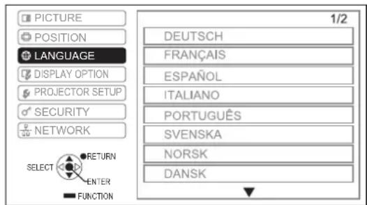

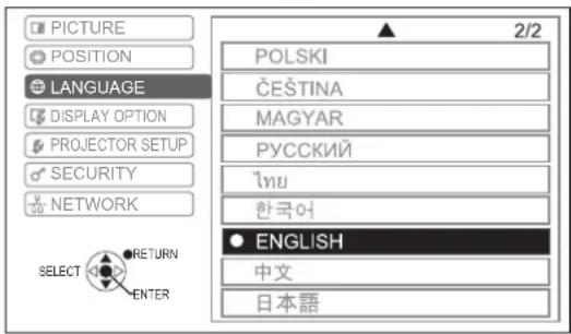
The set language is highlighted.
DISPLAY OPTION MENU
Set the selected item with [◀▶].
ON-SCREEN DISPLAY
You can set the on-screen display.

INPUT GUIDE
Set the display method of the input terminal name currently selected in the upper right corner of the screen.
| DETAILED | Display the input method using graphic.The INPUT GUIDE will go off if there is no operation after 10 seconds. |
| OFF Turn off the guide. | |
| SIMPLE | Display the input method using text.The INPUT GUIDE will go off if there is no operation after 5 seconds. |
Menu operation (continued)
Computer connection guide
You can switch the output signals from COMPUTER1/COMPUTER2 terminal by pressing the following computer command keys.
| Manufacturer | Image output selection command |
| Panasonic NEC | Fn + F3 |
| SAMSUNG HP | Fn + F4 |
| acer SHARP TOSHIBA | Fn + F5 |
| Manufacturer | Image output selection command |
| lenovo LG SONY | |
| DELL EPSON | |
| FUJITSU | |
| Apple |
NOTE:
The command keys depend on the manufacturers. • For detailed information, please refer to the instructions provided with the computers.
If you want to turn off the computer connection guide, select • SIMPLE or OFF.
OSD DESIGN
You can change the background of the on-screen menu (OSD).
| TYPE1 Semi | transparent black |
| TYPE2 Solid | blue |
| TYPE3 Semi | transparent dark blue |
WARNING MESSAGE
You can choose to or not to display the warning messages.
| ON | Warning messages will be displayed |
| OFF No display | |
NOTE:
- When the WARNING MESSAGE is set to OFF, use the projector with utmost care as most of the warning messages will not be displayed.
CLOSED CAPTION SETTING
If the input signal contains closed captions, you can turn on the feature and switch channels.
CLOSED CAPTION
| OFF Deactive |
| ON Active |
MODE
| CC1 - 4 Change the channels CC1 - 4 |
NOTE:
VCR with TBC (Time Base Corrector) function is recommended for video cassette tapes.
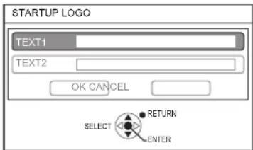
STARTUP LOGO
You can set the Panasonic logo, your own image or Pre-set letters to be displayed at the start of the projection.
Change setting

Change setting
| ON Display “Panasonic” logo | |
| TEXT Display the original text | |
| USER | Display the image registered by the user |
| OFF No display | |
NOTE:
- If TEXT is selected, the input letters are displayed at the start of the projection. You can display 2 lines of original text which contains up to 40 characters each.
- If USER is selected, the image transferred by the Logo Transfer Software is displayed at the start of the projection. (You can install the Logo Transfer Software from the provided CD-ROM.)
- STARTUP LOGO will be displayed for 30 seconds.
Menu operation (continued)
Editing the original text
1 Press [◀▶] to select TEXT and then press [ENTER].
2 Press [▲▼] to select the desired line and then press [ENTER].
You can input and edit the text for the first line in TEXT1 and the text for the second line in TEXT2.
3 Press [▲▼◀▶] to select the desired character and then press [ENTER].
To delete all the input characters, move the cursor to ALL DELETE and then press [ENTER].
To delete a character, press [DEFAULT] or move the cursor to select the character then press [DEFAULT].
![TEXT CHANGE A B C D E F G H I J K L M N O P Q R S T U V W X Y Z a b c d e f g h i j k l m n o p q r s t u v w x y z 1 2 3 4 5 6 7 8 9 0 SPACE ! " # $ % & ' * + - / = ? @ \ * , | | ~ ( ) < > [ ] { } . . : : OK CANCEL SELECT RETURN DELETE ENTER](/content/2026/03/515987/images/45ffd4db05e4a439ed115b0ced42c7831b421d04c4f4b6bc168d524a1ac17bd0.jpg)
4 Select OK and then press [ENTER] to set the input text in the box.
5 Select OK again and then press [ENTER]. Select CANCEL or press [MENU/RETURN] to return to the previous menu without any setting.
AUTO SETUP
AUTO mode is selected by default.
If you do not need to perform automatic correction, select "BUTTON".
Change setting

Change setting
| AUTO | When the projector detectsCOMPUTER signal, SHIFT, DOT CLOCK and CLOCK PHASE in the POSITION menu is automatically set. |
| BUTTON | Only when [AUTO SETUP] is pressed, SHIFT, DOT CLOCK and CLOCK PHASE in POSITION menu will be automatically set for COMPUTER signals. (⇒ page 23) |
SIGNAL SEARCH
You can turn off the auto signal detection.
Change setting

Change setting
| ON | Detects the input signal from the terminals and projects the image |
| OFF | Deactive |
NOTE:
SIGNAL SEARCH• is not available during any input signal projection.
BACK COLOR
You can choose BLUE or BLACK screen for the projector when it is idle.
Change setting

Change setting
| BLUE | Display blue screen |
| BLACK Display black screen | |
Menu operation (continued)
WIDE MODE
Set this mode when projecting wide signals (16:9, 16:10, 15:9).
Change setting
Change setting
| AUTO Automatic setting |
| OFF For 4:3 signals |
| ON For WIDE signals |
SXGA MODE
Set this mode when an SXGA signal is input and the projected image is trimmed.
Change setting

Change setting
SXGA For normal projection
SXGA+ For projection when image is cropped
OTHER FUNCTIONS
You can perform some of the remote control button operations from the sub-menu.
AUTO SETUP
For details, see "SET UP THE IMAGE POSITION AUTOMATICALLY". (⇒ page 23)
FREEZE
You can capture the projected image as a still picture. While the image is frozen, the audio sound through the projector will stop.
Press [RETURN] to escape.
The image is distorted momentarily when the projection is stopped and restarted.
AV MUTE
You can temporarily stop projection and audio sound when the projector is left idle.
Press [MÊNÚ] to escape.
INDEX-WINDOW
For details, see "INDEX-WINDOW display". (⇒ page 24)
DIGITAL ZOOM
[▶] button: zoom in [◀] button: zoom out
Press [ENTER] to select the enlargement.
Press [MENU] to escape.
The image is distorted momentarily when the image is zoomed.
PROJECTOR SETUP MENU
Set the selected item with [ ◀▶ ].
STATUS
You can check the projector's status.
SIGNAL
NAME → Name of input signal
FREQUENCY → Scanning frequency of input signal
RUNTIME
PROJECTOR → Display the projector's current usage time
LAMP → Display the lamp's current usage time
Menu operation (continued)

SIGNAL SHUT-OFF
If no image signal is input for the time set using the timer, the projector will automatically enter into standby mode.
Change setting

Change setting
| DISABLE NO SIGNAL SHUT-OFF is disabled | |
| 15 – 60 MIN. | Timer can be set at a 5-minute intervals |

TIAL START UP
You can set the starting method when the power plug is connected to wall outlet.
Change setting

Change setting
| LAST MEMORY | Projector starts from the last image before the power plug was disconnected |
| STANDBY | Projector starts in the standby mode |
| ON Projector starts immediately | |

TALLATION
When installing the projector, select the projection method according to the projector's position. (⇒ page 15)
Change setting

Change setting

GH ALTITUDE MODE
If you use the projector at high elevation, the HIGH ALTITUDE MODE setting need to be ON to set the fan speed to high.
Change setting

Change setting
| OFF | Use in normal environment (below 1 400 m (4 593 ft) above sea level) |
| ON | Use at high altitude (at 1 400 m – 2 700 m (4 593 - 8 858 ft) above sea level) |
NOTE:
The loudness of fan noise depends on the • HIGH ALTITUDE MODE setting.

TANDBY MODE
You can change the standby mode setting.
Change setting

Change setting
| ECO | The standby power is reduced to 0.4 W to save power |
| NORMAL | The power of the projector can be turned ON and the audio output can be set active by controlling the computer connected via wired LAN in standby mode |

AMP POWER
You can adjust the power of the lamp to save electricity, prolong the lamp life and reduce the noise.
Change setting

Change setting
| NORMAL When higher luminance is required |
| ECO When lower luminance is sufficient |
NOTE:
This function is disabled when no input signal is detected. ECO· setting is recommended when higher luminance is not required such as in a small room.
Menu operation (continued)
LAMP RUNTIME
You can check how long the lamp has been used.
NOTE:
LAMP RUNTIME• is important for lamp replacement timing.
See "REPLACE THE LAMP UNIT". (⇒ page 45)
Check the lamp unit replacement time. •( page 45)
If the lamp runtime has reached 3 800 hours, the red (time indicator) and gray marks appear alternately to notify you of the lamp replacement time.
The lamp life varies depending on the usage condition • (number of power-on times, etc.).
BMULATE
When the projector is controlled by a computer through serial input terminal, you can change the setting to use the former projector control commands.

2 To select the required setting.


| • DEFAULT | LB2 SeriesLB1 SeriesLB75 SeriesLB78 SeriesLB80 SeriesLB90 Series |
| D3500 D3500 | |
| D4000 D4000 | |
| D/W5K series | D5500 SeriesDW5000 SeriesD5600 SeriesDW5100 SeriesD5700 Series |
| D/W/Z6K series | D5000 SeriesD6000 SeriesDW6300 SeriesDZ6700 SeriesDZ6710 Series |
| L730 | L520 SeriesL720 SeriesL730 Series |
| L780 | L750 SeriesL780 Series |
| L735 L735 Series | |
| L785 L785 Series | |
| F/W series | F100 SeriesFW100 SeriesF200 SeriesF300 SeriesFW300 Series |
NOTE:
Some commands are not available. For details, please contact your dealer.
38 → ENGLISH
FUNCTION BUTTON
You can select a useful function from the list and assign it to [FUNCTION] button as a short-cut.
MENU

FUNCTION

To display the on-screen menu (main menu, sub-menu or detailed menu).
For the menu operation, see "OPERATE THE MENU".
(⇒ page 26)
Press and hold for at least 3 seconds.
When not using the [FUNCTION] button ( page 25)
NOTE:
The text and button color will change once the setting has completed.
AUDIO SETTING
You can perform detailed setting for Audio.
VOLUME
You can adjust the volume of the built-in speakers and audio output sound.
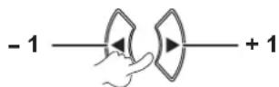
BALANCE
You can adjust to listen to the sound played equally from both right and left external stereo speakers, or adjust the balance so that more sound plays from either the left or right side.

Menu operation (continued)
IN STANDBY MODE
You can turn ON or OFF the audio output in standby mode.
Change setting

Change setting
| OFF Deactive | |
| ON | Active |
NOTE:
- When STANDBY MODE is set to ECO, the audio output cannot be activated in the standby mode, even if ON is selected.
AUDIO IN SELECT
You can select the AUDIO IN 1 or AUDIO IN 2 terminal to connect the audio output of the devices connected to COMPUTER 1 IN or COMPUTER 2 IN.
Change setting

Change setting
AUDIO IN SELECT
| COMPUTER1 IN | Select AUDIO IN 1 orAUDIO IN 2 terminal |
| COMPUTER2 IN | Select AUDIO IN 1 orAUDIO IN 2 terminal |
TEST PATTERN
You can use the 7 different test patterns to adjust the focus of the image.

To display the test pattern.
Change pattern
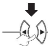
Change pattern
Press [MENU] or [RETURN] to return to the PROJECTOR SETUP menu, or press repeatedly to escape the menu mode.
NOTE:
The initial screen is an all white pattern. Only when • TEST PATTERN is assigned to the [FUNCTION] button, the lattice pattern will be displayed as the initial screen.
INITIALIZE ALL
You can reset all of the customized settings in MENU to the factory default.
- If the [ENTER] is pressed in the INITIALIZE ALL menu, "INITIALIZE ALL" will be displayed. Select OK and press [ENTER], "NOW INITIALIZING..." is displayed followed by "POWER OFF" display. Select OK and turn the power off according to the instruction. (All other buttons are deactivated.)
- The LANGUAGE and INITIAL SETTING menu screen will be displayed when the power is connected. (⇒ page 10)
NOTE:
The usage time of the projector, lamp runtime and the • NETWORK settings will not be initialized.
- When PASSWORD in SECURITY menu is activated, ensure to enter the correct password when initializing.
- After INITIALIZE ALL operation is completed, the password is reset to the factory default setting and PASSWORD setting is turned OFF.
Menu operation (continued)
SECURITY MENU
Remote control Control panel
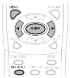
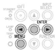
Set the selected item with [◀▶].
When you use SECURITY menu for the first time, you will be asked to perform the password operation. Input the initial password by pressing [▲▶▼◀▲▶▼◀] in this order and then press [ENTER].
NOTE:
If you have changed the password, input the new password • and press [ENTER].
PASSWORD
You can activate the security system and the password operation will be asked to perform when projection mode starts.
Change setting

Change setting
OFF Deactive
ON Active
NOTE:
- PASSWORD is set to OFF by default and when initialized. Change your password regularly. Do not use a simple • password that is easy to decode.
Unless you perform the correct password operation, all of the control buttons will be disabled except the [POWER] button.
PASSWORD CHANGE
You can change the password.

To change the password.
(Up to 8 button operations can be set.)

3 Input the password again and press the button.
NOTE:
The entered password operations will appear as asterisks in the box.
If the password input second does not match with the • password input first, an error message is displayed. In this case, input the correct password again.
TEXT DISPLAY
You can set your original text to display regularly at the bottom of the projected image during projection.
Change setting

Change setting
| OFF Deactive |
| ON Active |
- When CLOSED CAPTION SETTING is set to ON, SECURITY TEXT will not be displayed.
TEXT CHANGE
You can enter your original text to be displayed when TEXT DISPLAY is turned ON.

To select
the characters
(You can input up to 22 characters.)
To delete all the entered characters, move the cursor to ALL DELETE and press [ENTER].
Menu operation (continued)
To delete a character, press [DEFAULT] or move the cursor to the required character then press [DEFAULT].
![TEXT CHANGE A B C D E F G H I J K L M N O P Q R S T U V W X Y Z a b c d e f g h i j k l m n o p q r s t u v w x y z 1 2 3 4 5 6 7 8 9 0 SPACE ! * # $ % & ' * + - / = ? @ \ * _ ` | ~ ( ) < > [ ] { } . : . OK CANCEL SELECT RETURN DELETE ENTER](/content/2026/03/515987/images/d52f824c8cff8d95fad441184918e6653ecc81f9c4d3391c3e27b7da3bb9e8d1.jpg)
2

To select
OK
Select CANCEL or press [MENU/RETURN] to return to the previous menu without setting.

ENU LOCK
Press [MENU] to display the menu. You can lock or unlock the menu operation.
Change setting

Change setting
| OFF Unlock the menu operation | |
| ON Lock | the menu operation |
NOTE:
- Once MENU LOCK is set to ON, you cannot use the [MENU] button unless you input the correct password.
- The MENU LOCK is set to OFF by default and when initialized.

ENU LOCK PASSWORD
You can set a MENU LOCK PASSWORD.
1

To select
the characters
(You can input up to 16 characters.)
To delete all the entered characters, move the cursor to ALL DELETE and press [ENTER]. To delete a character, press [DEFAULT] or move the cursor to the required character then press [DEFAULT].
![MENU LOCK PASSWORD A B C D E F G H I J K L M N O P Q R S T U V W X Y Z a b c d e f g h i j k l m n o p q r s t u v w x y z 1 2 3 4 5 6 7 8 9 0 SPACE ! " # $ % & ' * + - / = ? @ \ " . ` ` ( ) < > [ ] ( ), . : ; OK CANCEL SELECT RETURN DELETE ENTER](/content/2026/03/515987/images/d0ddd348a37bd0990aadf38a5affdda2dd98da3f7660e8309f543a7475d78a86.jpg)
2

To select
OK
Select CANCEL or press [MENU/RETURN] to return to the previous menu without setting.
NOTE:
When using the projector for the first time or after • INITIALIZE ALL operation is activated, the initial password is set to AAAA.
Change your password regularly. Do not use a simple • password that is easy to decode.
- To reset the password to the initial password, see MENU LOCK PASSWORD. (⇒ page 52)
Menu operation (continued)
CONTROL DEVICE SETUP
You can enable/disable the button operations of the control panel and remote control.
Change setting

Change setting
CONTROL PANEL
| ENABLE Enable the button operations |
| DISABLE Disable the button operations |
REMOTE CONTROLLER
| ENABLE Enable the button operations |
| DISABLE Disable the button operations |
NOTE:
- If DISABLE is selected and [ENTER] is pressed, the confirmation screen appears. Select OK and press [ENTER].
- If any button is pressed after CONTROL PANEL is set to DISABLE, the password screen appears. Input the password which is set in the SECURITY menu. (If no operation is done, the password screen disappears in 10 seconds.)
If you set both • CONTROL PANEL and REMOTE CONTROLLER to DISABLE, all buttons' operations of the control panel and remote control are disabled and you cannot turn off the power.
How to clear DISABLE:
During the standby mode or projection, press and hold [ENTER] and [MENU] for at least 2 seconds, and CONTROL PANEL is set to ENABLE.
Change the setting of REMOTE CONTROLLER with the control panel.
NETWORK MENU
Remote control Control panel
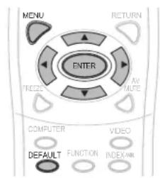
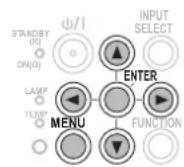
Set the selected item with [◀▶].
NOTE:
These items are set for network connection with a • computer. For details of the PJ Link and network, see "Network Operation Manual".
WIRED LAN
You can set up a wired LAN.
NAME CHANGE
You can change the name of the projector.
NETWORK CONTROL
When controlling the projector with a computer on the network, you must turn this function ON.
STATUS
You can display the status of the network setting.
INITIALIZE
You can reset the settings of the network to the factory default settings.
NOTE:
- If PASSWORD (SECURITY menu) is activated, when the network setting is initialized, you will be required to input the password.
LAMP and TEMP indicators
The LAMP and/or TEMP indicators will light up to indicate that the projector has some problems.
NOTE:
Make sure to turn off the power • (see "TURN THE PROJECTOR OFF" on page 21) and confirm the power supply status with the POWER indicator. (⇒ page 19)
TEMP indicator LAMP indicator
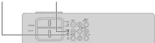
Manage the problem as follows:
LAMP INDICATOR
| Indicator | • Illuminating red | • Flashing red | ||
| Problem | LAMP RUNTIME has reached 3 800 hours. | LAMP circuit failure, abnormal function or the lamp unit is damaged. | ||
| Cause | Lamp unit will run out soon and needs to be replaced. | The projector is turned on again too soon. | LAMP circuit failure, abnormal function. | Lamp unit is damaged. |
| Remedy | See “REPLACE THE LAMP UNIT”. (⇒ page 45) | Let the lamp unit cool down and turn on the projector after 90 seconds. | Turn the projector off (⇒ page 21) and contact an Authorized Service Center. | See “REPLACE THE LAMP UNIT”. (⇒ page 45) |
NOTE:
- If the LAMP indicator still lights or flashes after the above remedy, contact an Authorized Service Center.
TEMP INDICATOR
| Indicator | Illuminating red while projecting and the alert will be displayed.·Flashing red and power is turned off.· | |||
| Problem | The temperature inside and/or outside the projector is abnormally high.The projection may become darker than usual.·The internal fan's operational noise may be louder than usual.· | |||
| Cause | The air outlet port and air intake ports are covered. | The room temperature is too high. | The filter is excessively dirty and the ventilation is poor. | The projector is located at 1 400 - 2 700 m (4 593 - 8 858 ft). |
| Remedy | Remove object(s) from the air outlet port and air intake ports or clear around the projector. | Reinstall the projector in temperature controlled place.(⇒ page 54) | Clean the filter in a proper method.(⇒ page 44) | Turn on the projector*1and set the HIGH ALTITUDE MODE to ON. (⇒ page 37) |
*1 The projector will operate for 2 minutes with OFF set at high elevation.
NOTE:
- Perform the above remedy; disconnect the power plug, and then supply the power again. If the TEMP indicator still lights or flashes after the above remedy, contact an Authorized Service Center.
- If temperature in the projector rises, the fan speed increases and the sound becomes louder.
Care and replacement
Preparations
Before cleaning, be sure to turn off the power and disconnect the power plug from the wall outlet. ( page 18, 21)
CLEANING THE PROJECTOR
Cabinet
Wipe off dirt and dust gently with a soft cloth.
If it is difficult to remove the dirt, wipe the projector with a damp cloth. Dry off the projector with dry cloth.
- Do not use petroleum benzine, thinner, any alcoholic solvent, kitchen detergents or chemical cloths. Failure to observe these may result in altered or damaged surfaces of the projector.
Projector lens
Make sure no dirt or dust remains on the surface of the projector lens glass. It will be enlarged and projected onto the screen.
Wipe off dirt and dust gently with a lint-free cloth. Do not wipe the projector lens with a cloth which has collected dust.
NOTE:
Clean the projector lens with special care.
Air filter
If the air filter is excessively dirty, the internal temperature of the projector increases, the TEMP indicator lights, and the power is turned off.
If the power is turned off, the TEMP indicator flashes.
Clean the air filter regularly every 100 hours of usage.
1 Remove the air filter.
While pressing the tab of the air filter, pull the air filter open slowly.
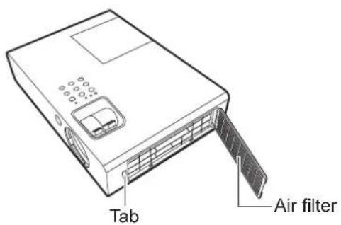
2 Clean the air filter.
Vacuum dirt and dust from the air filter.

natural_image
Line drawing of a hand using a knife to cut a rectangular object (no text or symbols)3 Install the air filter.
Install in the reverse order to 1).
NOTE:
- Do not use the projector without attaching the air filter. Otherwise, it will suck in dirt and dust which can cause malfunction.
- The TEMP indicator may flash because of clogging within 100 hours, depending on the using environment. In that case, clean the air filter at shorter intervals.
Care and Replacement (continued)
REPLACE THE LAMP UNIT
Air filter
The air filter should be replaced when cleaning is ineffective and when replacing the lamp unit. A replacement air filter is provided with a replacement lamp unit (ET-LAB2). Contact an Authorized Service Center for the air filter (TXFKN01VKN5).
Lamp unit
The lamp unit, ET-LAB2 is consumable and you must replace it regularly. It is recommended that a qualified technician carry the lamp unit replacement. Consult with an Authorized Service Center.
Note on lamp unit replacement
Handle the lamp unit with special care as the lamp is made of glass.
Dropping or giving it a shock may cause it to burst or damaged.
If you wish to discard the used lamp, please contact your local authorities or dealer and ask for the correct method of disposal.
Prepare a Phillips-head screwdriver.
When replacing the lamp unit, be sure to hold it by the handle.
Hold the lamp unit horizontally to prevent broken pieces from scattering.
When the projector is mounted in the ceiling, do not work directly under the projector or put your face close to the projector.
Pull out the lamp vertically.
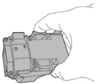
natural_image
Line drawing of a hand holding a mechanical component (no text or symbols)NOTE:
Prior to replacing the lamp unit, allow it to cool down to prevent the risk of burns, damage and other hazards.
Do not attempt replacement of an unauthorized lamp unit.
The model Nos. of the accessories and the parts sold separately are subject to change without notice.
Lamp unit replacement time
When the lamp has expired, the brightness may decrease over time. 4 000 hours of use is a rough guide of the replacing time and that might be shortened due to usage conditions, specifications of the lamp unit or environmental conditions. You can check the duration of usage time by checking LAMP RUNTIME in the PROJECTOR SETUP menu. Do not use a lamp unit over 5 000 hours. Failure to observe this may result in explosion of the lamp.
| ON-SCREEN DISPLAYREPLACE LAMP | LAMP indicatorLAMP | |
| 3 800 hours | Display “REPLACE LAMP” at the upper left of the screen for 30 seconds. If any button is pressed within 30 seconds, the message disappears. | Illuminates red, even in the standby mode. |
| 5 000 hours | Display “REPLACE LAMP” at the upper left of the screen, and it will stay until you respond. The power is turned off automatically in 10 minutes. |
NOTE:
The guide time, 4 000 hours, is a rough estimate based on certain conditions and is not a guaranteed time.
Care and Replacement (continued)
Lamp replacement procedure
- When the projector is mounted in the ceiling, do not work directly under the projector or put your face close to the projector.
- Be sure to install the lamp unit and attach the lamp unit cover securely. If they are not securely installed, it may cause the protection circuit to operate and the power cannot be turned on.
1 Disconnect the power plug from the wall outlet according to "TURN THE PROJECTOR OFF" (⇒ page 21), wait for at least 1 hour and check the bottom if the lamp unit has cooled.
2 Use a Phillips-head screwdriver to loosen the 1 lamp unit cover screw on the back of the projector until the screw loosen and remove the lamp unit cover.
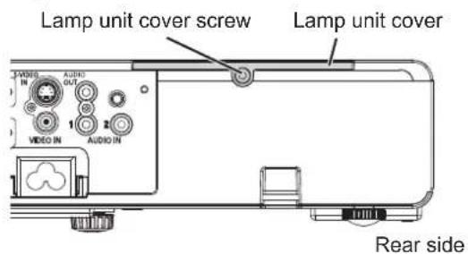
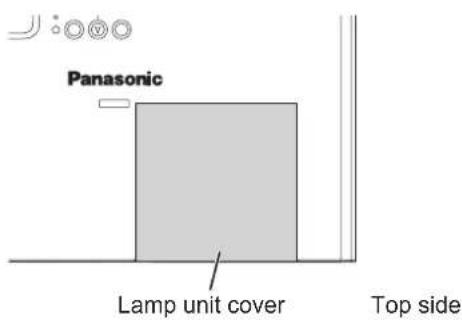
3 Use a Phillips-head screwdriver to loosen the 2 lamp unit screws. Pull the used lamp unit gently from the projector.

4 Press in the lamp unit until it clicks and make sure the unit is installed securely. Tighten the 2 lamp unit screws securely with a Phillips-head screwdriver.
During insertion, particularly press the ⊕ portion securely.
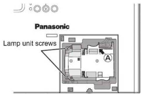
5 Attach the lamp unit cover and tighten the 1 lamp unit cover screw securely with a Phillips-head screwdriver.
6 Connect the power cord to a wall outlet.
7 Press [POWER] to begin projection.
NOTE:
- If INITIAL START UP in the PROJECTOR SETUP menu is set to ON, the projector starts projecting when the power cord is connected to a wall outlet. (⇒ page 37)
8

To display the main menu.

To scroll to the
PROJECTOR SETUP
menu.
Care and Replacement (continued)
9


To select the PROJECTOR SETUP menu.
To select LAMP RUNTIME.
10

Press and hold for approximately 3 seconds.

LAMP RUNTIME
LAMP RUNTIME RESET.
OK
:PRESS
BUTTON
CANCEL
:PRESS ANY OTHER BUTTON
NOTE:
- If any button other than the [POWER] is pressed, the LAMP RUNTIME screen disappears and the lamp runtime is not reset. (Repeat from step 8 again).
11

After the lamp goes off, projection stops and the [POWER] button on the main unit lit red. Disconnect the power plug. The lamp runtime has been reset to "0".
Ceiling mount bracket safeguards
Installation work of the ceiling mount bracket should only be carried by a qualified technician.
- Even if it is during guaranteed period, the manufacturer is not responsible for any hazard or damage caused by using a ceiling mount bracket which is not purchased from an authorized distributors, or environmental conditions.
Remove an unused ceiling mount bracket promptly.
- Ensure to use a torque driver and do not use an electrical screwdriver or an impact screwdriver.
For details, see the work instruction manual packed together with the ceiling mount bracket.
- The model Nos. of the accessories and the parts sold separately are subject to change without notice.
Model No. of ceiling mount bracket: ET-PKB2
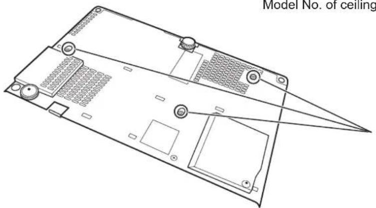
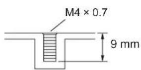
Torque:1.25 ± 0.2 N.m
Troubleshooting
Confirm the following problem and cause.
If the suggested solutions do not solve the problem, contact an Authorized Service Center.
| Problem Cause Page | ||
| Power does not turn on. | The power cord may not be connected securely. ●No electric supply at the wall outlet. ●The circuit breakers have tripped. ●TEMP or LAMP indicator is lit or flashes.The lamp unit cover has not been securely installed. ●CONTROL PANEL in the PROJECTOR SETUP menu is invalidated. | 18——434642 |
| No picture appears. | The lens cover is not removed. ●The input terminal may not be connected properly. ●The input selection setting may not be correct. ●The BRIGHTNESS adjustment setting may be at the minimum setting.●the signal input source may not be operating properly.●The AV MUTE function may be in use. | ——16, 172228——23 |
| The picture is fuzzy. | ●the lens focus may not have been set correctly.●the projector may not be at the correct distance from the screen.●the lens may be dirty.●the projector may be tilted too much. | 22144422 |
| Color is pale or grayish. | ●COLOR or TINT adjustment may be incorrect.●the input source which is connected to the projector may not be adjusted correctly. | 29— |
| No sound can be heard from the internal speaker. | ●the audio signal source may not be connected properly.●the volume adjustment may be at the lowest possible setting.●A cable may be connected to the AUDIO OUT terminal. | 16, 1724, 3812 |
| The remote control does not operate. | ●the batteries may be weak.●the batteries may not have been inserted correctly.●The remote control signal receptor on the projector may be obstructed.●the remote control unit may be out of the operation range.●REMOTE CONTROLLER in the PROJECTOR SETUP menu is invalidated.●The remote control is under a strong light such as fluorescent. | ——1313134213 |
| The control buttons of the projector do not operate. | ●CONTROL PANEL in the PROJECTOR SETUP menu is invalidated.(If you have a loss of the remote control while the CONTROL PANEL is invalidated, press and hold [MENU] for 2 seconds by pressing [ENTER].) | 42 |
| The picture does not display correctly. | ●The signal format (TV-SYSTEM, RGB/YPBPR) may not have been set correctly.●there may be a problem with the VCR or other signal source.●A signal which is not compatible with the projector is being input. | 29, 30——50 |
| Picture from a computer does not appear. | ●The RGB signal cable is too long. (Limit to 10 m (32' 10").●The external video output from a laptop computer may not be correct. (You may be able to change the external output settings by pressing the [Fn] + [F3] or [Fn] + [F10] keys simultaneously. The actual method varies depending on the type of computer; refer to the documentation provided with your computer for further details.) | ——34 |
| The projector cannot be controlled through serial terminal. | ●EMULATE in the PROJECTOR SETUP menu is not set correctly.(If you fail to select your product series, ask your dealer for repair.) | 38 |
Dimensions
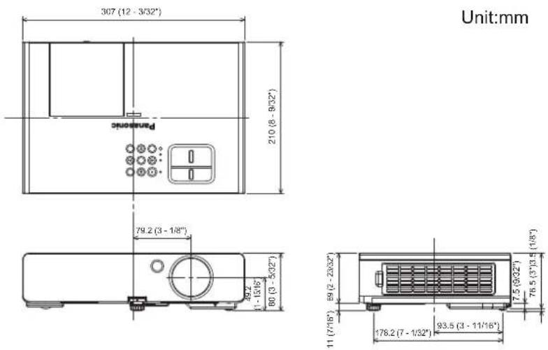
Trademark acknowledgements
VGA and XGA are trademarks of International Business Machines Corporation.
S-VGA is a registered trademark of the Video Electronics Standards Association.
HDMI, the HDMI logo and High-Definition Multimedia Interface are trademarks or registered trademarks of HDMI • Licensing LLC.
- The font used in the on-screen displays is a Ricoh bitmap font, which is manufactured and sold by Ricoh Company, Ltd.
All other trademarks are the property of the various trademark owners.
Technical information
LIST OF COMPATIBLE SIGNALS
This projector can project the following image signals.
| Mode | Display resolution (dots)*1 | Scanning frequency | Dot clock frequency (MHz) | Picture quality*2 | PnP availability*3 | Terminals | |
| H (kHz) V | (Hz) | ||||||
| NTSC/NTSC4.43/PAL-M/PAL60 | 720 × 480i 15.7 | 59.9 — A | VIDEO/S-VIDEO | ||||
| PAL/PAL-N/SECAM 720 × 576i 15.6 50 — A | |||||||
| 525i (480i) 720 × 480i 15.7 59.9 13.5 A | RGB/YPBPR | ||||||
| 625i (576i) 720 × 576i 15.6 50 13.5 A | |||||||
| 525p (480p) 720 × 483 31.5 59.9 27 | A | ||||||
| 625p (576p) 720 × 576 31.3 50 | 27 | A | |||||
| 1 125 (1 080)/60i | 1 920 × 1 080i 33 | 8 60 74.3 A | |||||
| 1 125 (1 080)/50i | 1 920 × 1 080i 28 | 1 50 74.3 A | |||||
| 1 125 (1 080)/60p | 1 920 × 1 080p | 67.5 | 60.0 | 148.5 | A | O | |
| 1 125 (1 080)/50p | 1 920 × 1 080p | 56.3 | 50.0 | 148.5 | A | O | |
| 750 (720)/60p | 1 280 × 720 45 | 60 74.3 A | |||||
| 750 (720)/50p | 1 280 × 720 37.5 | 50 74.3 A | |||||
| VESA | 640 × 400 31.5 | 70.1 25.2 A | RGB | ||||
| 640 × 400 37.9 | 85.1 31.5 A | ||||||
| VGA | 640 × 480 31.5 | 59.9 25.2 A | O | ||||
| 640 × 480 | 35 66.7 | 30.2 A | O | ||||
| 640 × 480 37.9 | 72.8 31.5 A | O | |||||
| 640 × 480 37.5 | 75 31.5 A | O | |||||
| 640 × 480 43.3 | 85 | 36 | A | ||||
| SVGA | 800 × 600 35.2 | 56.3 36 | A | O | |||
| 800 × 600 37.9 | 60.3 40 | A | O | ||||
| 800 × 600 48.1 | 72.2 50 | A | O | ||||
| 800 × 600 46.9 | 75 49.5 A | O | |||||
| 800 × 600 53.7 | 85.1 56.3 A | ||||||
| MAC | 832 × 624 49.7 | 74.6 57.3 A | O | ||||
| XGA | 1 024 × 768 39.6 | 50.1 51.9 | AA | ||||
| 1 024 × 768 48.4 | 60 | 65 | AA | O | |||
| 1 024 × 768 56.5 | 70.1 75 | AA | O | ||||
| 1 024 × 768 60 | 75 78.8 | AA | O | ||||
| 1 024 × 768 68.7 | 85 94.5 | AA | |||||
| MXGA | 1 152 × 864 64 | 71.2 94.2 A | O | ||||
| 1 152 × 864 67.5 | 74.9 | 108 | A | ||||
| 1 152 × 864 77.1 | 85 119.7 | A | |||||
| MAC | 1 152 × 870 | 68.7 | 75.1 | 100 | A | O | |
| MSXGA | 1 280 × 960 | 60 | 60 | 108 | A | O | |
| SXGA | 1 280 × 1 024 64 | 60 | 108 | A | |||
| 1 280 × 1 024 80 | 75 | 135 | A | O | |||
| 1 280 × 1 024 | 91.1 85 | 157.5 | A | ||||
| SXGA60+ | 1 400 × 1 050 64 | 60 | 108 | A | |||
| 1 400 × 1 050 | 65.1 | 59.9 | 122.4 | A | O | ||
| UXGA | 1 600 × 1 200 | 75 | 60 | 162 | A | O | |
| WIDE750 (720) | 1 280 × 720 44.8 | 59.9 74.5 A | O | ||||
| 1 280 × 720 37.1 | 49.8 60.5 A | ||||||
| WXGA768 | 1 280 × 768 39.6 | 49.9 65.3 A | |||||
| 1 280 × 768 47.8 | 59.9 79.5 A | O | |||||
| WXGA800 | 1 280 × 800 41.3 | 50 | 68 | A | |||
| 1 280 × 800 49.1 | 60.2 69.1 A | O | |||||
| 1 280 × 800 49.7 | 59.8 83.5 A | ||||||
| WXGA+ | 1 440 × 900 | 55.9 | 59.9 | 106.5 | A | O | |
| WSXGA+ | 1 680 × 1 050 | 65.3 | 60 | 146.3 | A | O | |
| WUXGA | 1 920 × 1 200 | 74.6 | 59.9 | 193.3 | B | ||
*1 The "i" appearing after the resolution indicates an interlaced signal.
*2 The following symbols are used to indicate picture quality.
AA : Maximum picture quality can be obtained.
A : Signals are converted by the image processing circuit before picture is projected.
B : Some loss of data occurs to make projection easier.
*3 The signals marked with circles (O) can be applied by plug-and-play device.
Technical Information (continued)
SERIAL TERMINAL
The serial connector which is on the connector panel of the projector conforms to the RS-232C interface specifications. The projector can be controlled by a personal computer which is connected to this connector.
Connection
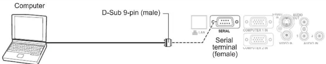
Pin assignments and signal names
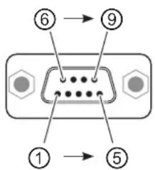
Communication settings
| Signal level RS-232C Character length 8 bits | ||
| Sync.method Asynchronous Stop bit 1 bit | ||
| Baud rate 9 600 bps X parameter None | ||
| Parity None | S parameter None |
Basic format
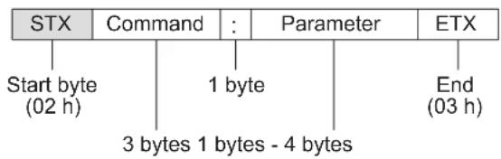
flowchart
graph TD
    A["Start byte (02 h)"] --> B["Command"]
    B --> C["1 byte"]
    C --> D["Parameter"]
    D --> E["ETX"]
    F["3 bytes 1 bytes - 4 bytes"] --> C
    F --> D
    F --> E
The data streaming from the computer will start with STX, and proceed to Command, Parameter and end with ETX.
You can add the required parameter.
NOTE:
- The projector cannot receive any command for 10 seconds after the lamp is switched on. Wait for 10 seconds before sending the command.
- For multiple commands, check the projector if the response has been sent for one command before sending the next command.
- When a command which does not require parameters to be sent, the colon (:) is not required.
- If an incorrect command is sent from the personal computer, an ER401 command will be sent from the projector to the personal computer.
Technical Information (continued)
Cable specifications
(When connected to a personal computer)
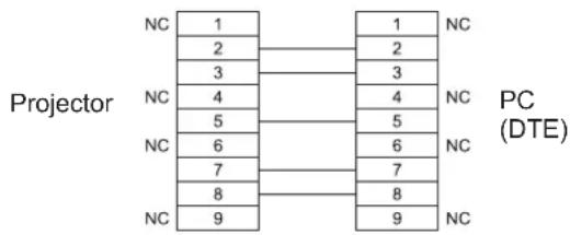
Control commands
The following commands are used for control of the projector with a computer. (Operation commands)
| Command Control contents Remarks | ||
| PON Power on | The PON command is ignored during lamp ON control.If a PON command is received while the cooling fan is operating after the lamp has switched off, the lamp is not turned back on again straight away in order to protect the lamp. | |
| POF Power off | ||
| AVL Volume | Parameter:000 - 063 (Adjustment value 0 - 63) | |
| IIS Input | Parameter:VID = VIDEO SVD = S-VIDEO RG1 = COMPUTER 1 INRG2 = COMPUTER 2 IN | |
| Q$S | Lamp condition query | Call back:0 = Standby 1 = Lamp on control active 2 = Lamp on 3 = Lamp off control active |
| OSH AV mute | Turn off the projection and sound temporarily.Send the command to switch between off and on. (⇒ page 23)Do not send the command consecutively.0 = Off 1 = On | |
NOTE:
- If STANDBY MODE is set to ECO, only PON and Q\\ command can be used in the standby mode.
MENU LOCK PASSWORD
To reset the password to the default setting AAAA, perform the following when the MENU LOCK PASSWORD request screen is displayed.
1) Press and hold the
2) Press and hold ▼ button for at least 2 seconds.
PASSWORD HAS BEEN INITIALIZED. is displayed on the MENU LOCK PASSWORD request screen.
Specifications
| Power supply AC 100 - 240 V 50 Hz/60 Hz | ||
| Power consumption | 300 WDuring standby (when fan is stopped):0.4 W (STANDBY MODE: ECO)15 W *1 (STANDBY MODE: NORMAL) | |
| Current 3.5 A - 1.2 A | ||
| LCD panel | Panel size (diagonal) 0.63 type (16.00 mm) | |
| Aspect ratio 4:3 | ||
| Display method 3 transparent LCD panels (RGB) | ||
| Drive method Active matrix method | ||
| Pixels 786 432 (1 024 × 768) × 3 panels | ||
| Lens | Manual zoom (1.2×)/Manual focusF 1.64 - 1.87, f 18.8 mm - 22.56 mm (PT-LB2U)F 2.0 - 2.2, f 19.22 mm - 22.68 mm (PT-LB1U) | |
| Lamp UHM lamp (220 W) | ||
| Luminosity *2 | 2 600 lm (PT-LB2U) 2 200 lm (PT-LB1U) | |
| Scanning frequency *3(for RGB signal) | Horizontal scanning frequency | 15 kHz - 91 kHz |
| Vertical scanning frequency | 50 Hz - 85 Hz | |
| Dot clock frequency Less than 170 MHz | ||
| COMPONENT (YPBPR) signals | 525i (480i), 525p (480p), 625i (576i), 625p (576p), 750 (720)/60p, 750 (720)/50p, 1 125 (1 080)/60i, 1 125 (1 080)/50i | |
| Color system 7 (NTSC/NTSC4.43/PAL/PAL-M/PAL-N/PAL60/SECAM) | ||
| Projection size 33" - 300" (838.2 mm - 7 620 mm) | ||
| Optical axis 5:1 fixed | ||
| Throw distance | 1.1 m - 11.5 m (3'7" - 37'8") (PT-LB2U)1.1 m - 11.7 m (3'7" - 38'4") (PT-LB1U) | |
| Screen aspect ratio | 4:3 | |
| Installation | FRONT/DESK, FRONT/CEILING, REAR/DESK, REAR/CEILING (Menu selection method) | |
| Speaker | 1 piece 4 cm × 2 cm (1 5/8" × 3/4") | |
| Max. useable volume output | 1.0 W (Monaural) | |
| Terminals | S-VIDEO IN | Single - line, Mini DIN 4pY: 1.0 V [p-p], C: 0.286 V [p-p], 75 Ω |
| VIDEO IN | Single - line, RCA pin jack1.0 V [p-p], 75 Ω | |
| COMPUTER IN | Dual - line, D-Sub HD 15-pin (female)● RGB inputR.G.B.: 0.7 V [p-p], 75 ΩG-SYNC: 1.0 V [p-p], 75 ΩHD, VD/SYNC: TTL high impedance, automatic positive/negative polarity compatible● YPBPR/YCBCRinputY: 1.0 V [p-p] (include sync), 75 ΩPB/CB, PR/CR: 0.7 V [p-p], 75 Ω | |
| AUDIO IN | Dual - line, 0.5 V [rms], M3 jack (Stereo MINI) | |
| AUDIO OUT | Single - line, M3 jack (Stereo MINI)Monitor output/stereo compatible0 V [rms] - 2.0 V [rms] (variable) | |
| SERIAL | Single - line, D-Sub 9-pin RS-232C compatible | |
| LAN (RJ-45) | Single - line, 10Base-T/100Base-TX | |
*1 When "IN STANDBY MODE" in AUDIO SETTING menu is ON: 18 W.
*2 Measurement, measuring conditions and method of notation all comply with ISO21118 international standards.
*3 See "LIST OF COMPATIBLE SIGNALS" on page 50 for available signals.
Specifications (continued)
| Cabinet | Moulded plastic (PC+ABS) | |
| Dimensions | Width: 307 mm (12 3/32") ●Height: 69 mm (2 23/32") ●Length: 210 mm (8 9/32") ●(not including surface projection parts) | |
| Weight | Approx. 2.3 kg (5.1 lbs.) *4 | |
| Operating environment | Temperature: 0 °C - 40 °C (32 °F - 104 °F) ●When the HIGH ALTITUDE MODE ( → page 37) is set to ON: 0 °C - 35 °C (32 °F - 95 °F) Humidity: 20 % - 80 % (no condensation) ● | |
| Certifications | UL60950-1 C-ULFCC Class B ICES-003 | |
| Remote control | Power supply | 3 V DC (AAA/R03 battery × 2) |
| Operating range | Approx. 7 m (23' 0") (when operated directly in front of signal receptor) | |
| Weight | Approx. 64 g (2.3 ozs.) (including batteries) | |
| Dimensions | Width: 45.6 mm (1 25/32") ●Length: 115 mm (4 17/32") ●● Height: 21.4 mm (27/32") (not including surface projection parts) | |
| Options *5 | Ceiling bracket | ET-PKB2 |
| Air Filter Unit | ET-KFB2 | |
*4 Average value. Each product has an individual variability in weight.
*5 The model Nos. of the accessories and parts sold separately are subject to change without notice.
Index
A
ASPECT 31
AUDIO SETTING 38
AUTO SETUP 35
AV MUTE 23
B
BACK COLOR 35
BRIGHTNESS 28
C
CAUTIONS ON USE 8
CAUTIONS WHEN INSTALLING ..... 7
CAUTIONS WHEN TRANSPORTING ... 7
CLEANING AND MAINTENANCE ..... 9
CLEANING THE PROJECTOR ..... 44
CLOCK PHASE 31
CLOSE CAPTION SETTING 34
COLOR 29
COLOR TEMPERATURE 29
COMPUTER 23
Connections...... 16
CONTRAST 28
CONTROL DEVICE SETUP 42
D
DAYLIGHT VIEW 29
DEFAULT 24
Dimensions 49
DISPLAY OPTION MENU 33
DISPOSAL 9
DOT CLOCK 30
E
EMULATE 38
ENLARGE THE IMAGE 25
F
FRAME LOCK 32
FREEZE 23
FUNCTION BUTTON 25,38
H
HIGH ALTITUDE MODE 37
1
Important Safety Notice 2
INDEX-WINDOW 24
INITIALIZE ALL 39
INITIAL SETTING 10
INITIAL START UP 37
INSTALLATION 37
K
KEYSTONE 30
L
LAMP INDICATOR 43
LAMP POWER 37
LAMP RUNTIME 38
LANGUAGE MENU 33
LANGUAGE.... 10
LIST OF COMPATIBLE SIGNALS ..... 50
M
MAIN MENU 27
MENU LOCK 41
MENU LOCK PASSWORD ...... 41, 52
N
NETWORK MENU 42
NOISE REDUCTION 29
NO SIGNAL SHUT-OFF 37
0
ON-SCREEN DISPLAY 33
ON-SCREEN MENU 26
OPERATE THE MENU 26
OTHER FUNCTIONS 36
OVER SCAN 31
P
PASSWORD 40
PASSWORD CHANGE 40
PICTURE MENU 28
PICTURE MODE 28
POSITION MENU 30
POSITION THE IMAGE 22
POWER CORD 18
POWER indicator status 19
PROJECTION METHOD 15
PROJECTOR SETUP MENU 36
PROJECTOR'S MAIN UNIT 11
PROJECTOR'S REMOTE CONTROL .... 13
R
REALTIME KEYSTONE 30
Remote control operation 23
REPLACE THE LAMP UNIT...... 45
RGB/YPBPR 30
s
SCREEN SIZE AND THROW DISTANCE 14
SECURITY 8
SECURITY MENU 40
SELECT THE INPUT SIGNAL ..... 22
SERIAL TERMINAL 51
SHARPNESS 29
SHIFT 30
SIGNAL SEARCH 35
Specifications 53
STANDBY MODE 37
STARTUP LOGO 34
STATUS 36
SUB MENU 27
SUPPLIED ACCESSORIES 9
SXGA MODE 36
T
TABLE OF CONTENTS 4
TEMP INDICATOR 43
TEST PATTERN 39
TEXT CHANGE 40
TEXT DISPLAY.... 40
TINT 29
Troubleshooting 48
TURN THE PROJECTOR OFF ..... 21
TURN THE PROJECTOR ON ..... 20
TV-SYSTEM 29
V
VOLUME 24
W
WHITE BALANCE 29
WIDE MODE 36
Removal of spacer at rear adjuster.
Remove the spacer before use.
Keep the spacer away from babies and infants.
If a baby swallows the spacer by accident, it may be affected badly.
If a baby seems to have swallowed the spacer, consult the doctor immediately.
REMARQUE:
MISE AU POINT DE L'OBJECTIF
natural_image
Line drawing of a hand holding a mechanical component (no text or symbols)REMARQUE :
This product contains a CR Coin Cell Lithium Battery which contains Perchlorate Material - special handling may apply.
See www.dtsc.ca.gov/hazardouswaste/perchlorate.
Panasonic Corporation
Web Site : http://panasonic.net/avc/projector/
© Panasonic Corporation 2010
Panasonic Solutions Company
3 Panasonic Way, Secaucus, NJ 07094
TEL: (877) 803 - 8492
Panasonic Canada Inc.
5770 Ambler Drive, Mississauga, Ontario L4W 2T3
TEL: (905) 624 - 5010
F0510-10710A
TQBJ0322-1
- Operating Instructions Basic Manual
- Important Safety Notice
- Dear Panasonic Customer:
- Serial number:
- WARNING
- NOTICE:
- Important Safety Notice (continued)
- WARNING:
- Declaration of Conformity
- Information on Disposal in other Countries outside the European
- TABLE OF CONTENTS
- Essential information
- Preparation
- Getting started
- Basic operations
- Settings
- Maintenance
- References
- Informations essentielles
- Standby power reduction
- User logo display function
- Precautions with regard to safety
- POWER
- ON USE/INSTALLATION
- Precautions with regard to safety (continued)
- Do not look and place your skin into the lights emitted from the lens while the projector is being used.
- Do not insert any foreign objects into the projector.
- Never attempt to remodel or disassemble the projector.
- Do not project an image with the supplied lens cover attached.
- ACCESSORIES
- Do not use or handle the batteries improperly, and refer to the following.
- Do not allow children to reach the AAA/R03 battery.
- If the battery fluid leaks, do not touch it with bare hands, and take the following measures if necessary.
- Do not disassemble the lamp unit.
- Lamp replacement
- Do not allow infants or pets to touch the remote control unit.
- CAUTION
- When disconnecting the power cord, be sure to hold the power plug and power connector.
- When not using the projector for an extended period of time, disconnect the power plug from the wall outlet and remove the batteries from the remote control.
- Disconnect the power plug from the wall outlet before carrying out any cleaning.
- Do not put your weight on this projector.
- Do not place the projector in extremely hot locations.
- Always disconnect all cables before moving the projector.
- Do not use the old lamp unit.
- If the lamp has broken, ventilate the room immediately. Do not touch or bring your face close to the broken pieces.
- CAUTIONS WHEN TRANSPORTING
- When transporting, keep the projector in the provided carrying bag with the lens cover on it.
- CAUTIONS WHEN INSTALLING
- DO NOT USE UNDER THE FOLLOWING CONDITIONS.
- Do not set up the projector outdoors.
- Avoid setting up in places which are subject to • vibration or shocks.
- Avoid setting up in places which are subject to • sudden temperature changes, such as near an air conditioner or lighting equipment.
- Avoid setting up in places which are near high-voltage power lines or near motors.
- - Do not install the projector at elevations higher than 2 700 m (8 858 ft) above sea level.
- BE SURE TO ASK A SPECIALIZED TECHNICIAN WHEN INSTALLING THE PRODUCT TO A CEILING.
- LENS FOCUS
- CAUTIONS ON USE
- IN ORDER TO GET THE PICTURE QUALITY
- DO NOT TOUCH THE SURFACE OF THE PROJECTOR LENS WITH YOUR BARE HAND.
- DO NOT MOVE THE PROJECTOR WHILE IT IS OPERATING OR SUBJECT IT TO VIBRATION OR IMPACT.
- THE PROJECTOR HAS A HIGH PRESSURE MERCURY LAMP THAT IS CHARACTERIZED AS FOLLOWS:
- CONNECTION TO EXTERNAL DEVICE
- OPTICAL COMPONENTS
- LIQUID CRYSTAL PANEL
- SECURITY
- TAKE SAFETY MEASURES AGAINST FOLLOWING INCIDENTS.
- SECURITY INSTRUCTION
- CLEANING AND MAINTENANCE
- ASK AN AUTHORIZED SERVICE CENTER TO CLEAN THE INSIDE OF THE PROJECTOR AT LEAST ONCE A YEAR.
- DISPOSAL
- SUPPLIED ACCESSORIES
- NOTE:
- Start-up display
- LANGUAGE
- 1
- 2
- INITIAL SETTING
- 3
- Details of your projector
- PROJECTOR'S MAIN UNIT
- Top and front view
- Control Panel / Indicators
- Details of your projector (continued)
- Rear and bottom view
- Terminals
- PROJECTOR'S REMOTE CONTROL
- Top and rear view
- Installing/removing batteries
- Front view
- ① POWER
- Set up your projector
- SCREEN SIZE AND THROW DISTANCE
- Set up your projector (continued)
- PROJECTION METHOD
- Connections
- Preparations
- Example: AV equipment
- Connections (continued)
- Example: Computers
- Turn the projector ON or OFF
- POWER CORD
- Install the "power cord secure lock" Detach the "power cord secure lock"
- Direct power on function
- Direct power off function
- Turn the projector ON or OFF (continued)
- POWER INDICATOR
- TURN THE PROJECTOR ON
- TURN THE PROJECTOR OFF
- Press the POWER button.
- Press the button again.
- Disconnect the power plug from the wall outlet after the POWER indicator turns red.
- Project an image
- SELECT THE INPUT SIGNAL
- Switch on the connected devices.
- Select an input signal.
- POSITION THE IMAGE
- Adjust the vertical angle of the projector.
- Adjust the projection size and focus.
- Remote control operation
- CAPTURE AN IMAGE
- STOP THE PROJECTION TEMPORARILY
- SWITCH THE INPUT SIGNAL
- COMPUTER
- VIDEO
- SET UP THE IMAGE POSITION AUTOMATICALLY
- Remote control operation (continued)
- RESET TO FACTORY DEFAULT SETTINGS
- CONTROL SPEAKER VOLUME
- PROJECT AN IMAGE USING INDEX-WINDOW
- INDEX-WINDOW display
- ENLARGE THE IMAGE
- [DIGITAL ZOOM] button operation
- USE AN ASSIGNED FUNCTION
- When not using the [FUNCTION] button
- Menu operation
- OPERATE THE MENU
- ON-SCREEN MENU
- Menu operation (continued)
- MAIN MENU
- SUB MENU
- PICTURE menu
- POSITION menu
- LANGUAGE menu
- DISPLAY OPTION menu
- PROJECTOR SETUP menu
- SECURITY menu
- NETWORK menu
- PICTURE MODE
- CONTRAST
- BRIGHTNESS
- COLOR
- TNT
- SHARPNESS
- WHITE BALANCE
- COLOR TEMPERATURE
- DAYLIGHT VIEW
- NOISE REDUCTION
- TV-SYSTEM
- RGB/YPBPR
- Change setting
- REALTIME KEYSTONE
- HEYSTONE
- SHIFT
- NOT CLOCK
- QLOCK PHASE
- QVER SCAN
- ASPECT
- AUTO (For NTSC/480i input signal only)
- 4:3
- 16:9
- H FIT
- V FIT
- HV FIT
- S4:3
- THROUGH
- FRAME LOCK
- ON-SCREEN DISPLAY
- INPUT GUIDE
- Computer connection guide
- OSD DESIGN
- WARNING MESSAGE
- CLOSED CAPTION SETTING
- STARTUP LOGO
- Editing the original text
- AUTO SETUP
- SIGNAL SEARCH
- BACK COLOR
- WIDE MODE
- SXGA MODE
- OTHER FUNCTIONS
- FREEZE
- AV MUTE
- INDEX-WINDOW
- DIGITAL ZOOM
- STATUS
- SIGNAL
- RUNTIME
- SIGNAL SHUT-OFF
- TIAL START UP
- TALLATION
- GH ALTITUDE MODE
- TANDBY MODE
- AMP POWER
- LAMP RUNTIME
- BMULATE
- → ENGLISH
- FUNCTION BUTTON
- AUDIO SETTING
- VOLUME
- BALANCE
- IN STANDBY MODE
- AUDIO IN SELECT
- TEST PATTERN
- INITIALIZE ALL
- PASSWORD
- PASSWORD CHANGE
- TEXT DISPLAY
- TEXT CHANGE
- ENU LOCK
- ENU LOCK PASSWORD
- CONTROL DEVICE SETUP
- WIRED LAN
- NAME CHANGE
- NETWORK CONTROL
- INITIALIZE
- LAMP and TEMP indicators
- Care and replacement
- CLEANING THE PROJECTOR
- Cabinet
- Projector lens
- Air filter
- Remove the air filter.
- Clean the air filter.
- Install the air filter.
- Care and Replacement (continued)
- REPLACE THE LAMP UNIT
- Lamp unit
- Note on lamp unit replacement
- Lamp unit replacement time
- Lamp replacement procedure
- Ceiling mount bracket safeguards
- Troubleshooting
- Dimensions
- Trademark acknowledgements
- Technical information
- LIST OF COMPATIBLE SIGNALS
- Technical Information (continued)
- SERIAL TERMINAL
- Connection
- Pin assignments and signal names
- Communication settings
- Basic format
- Cable specifications
- Control commands
- MENU LOCK PASSWORD
- Index
- A
- B
- C
- D
- E
- F
- H
- K
- L
- M
- N
- 0
- P
- R
- s
- T
- V
- W
- REMARQUE:
- MISE AU POINT DE L'OBJECTIF
- REMARQUE :
- Panasonic Corporation
- Panasonic Solutions Company
- Panasonic Canada Inc.
Brand : PANASONIC
Model : PTLB2U
Category : Projector