UR201CZ - Grass trimmer MAKITA - Free user manual and instructions
Find the device manual for free UR201CZ MAKITA in PDF.

User questions about UR201CZ MAKITA
0 question about this device. Answer the ones you know or ask your own.
Ask a new question about this device
Download the instructions for your Grass trimmer in PDF format for free! Find your manual UR201CZ - MAKITA and take your electronic device back in hand. On this page are published all the documents necessary for the use of your device. UR201CZ by MAKITA.
USER MANUAL UR201CZ MAKITA
natural_image
Technical line drawing of two mechanical device holders with adjustable arms and connectors (no text or symbols)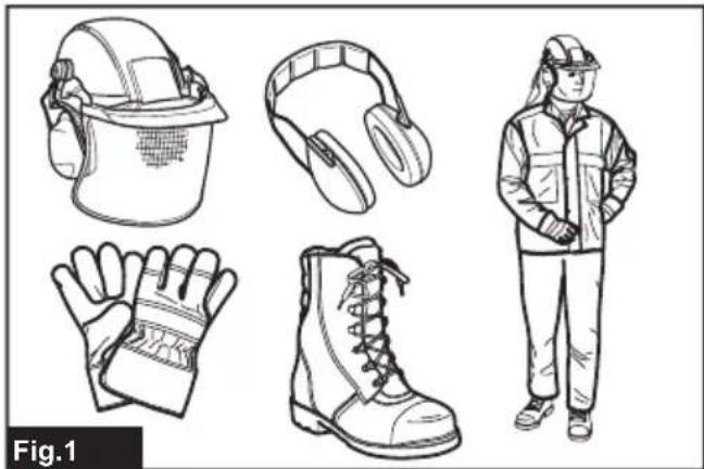
natural_image
Line drawings of various safety gear and equipment including a helmet, hard hat, gloves, and a worker in uniform (no text or symbols)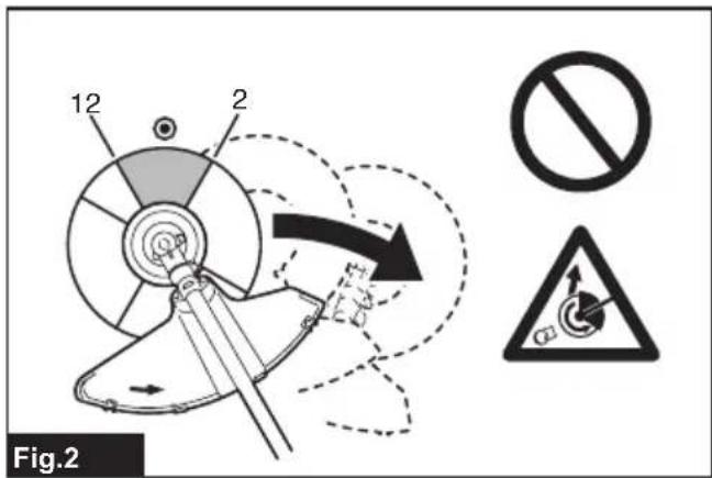
text_image
12 2 Fig.2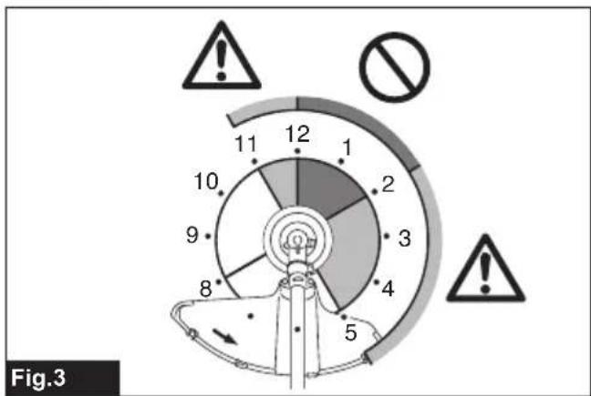
text_image
12 1 2 3 4 5 8 9 10 11 Fig.3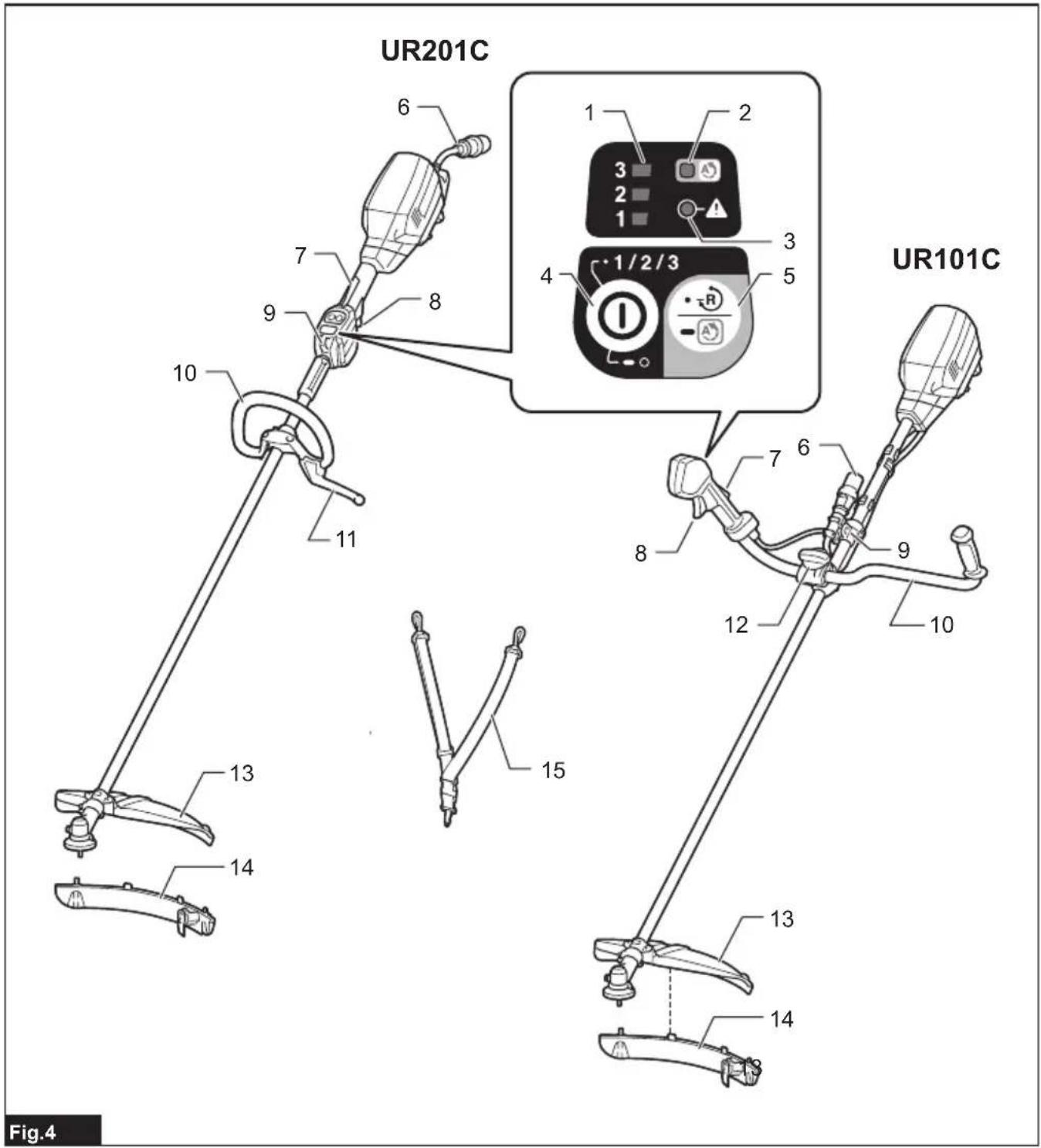
text_image
UR201C UR101C Fig.4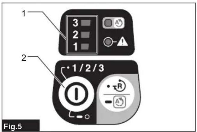
text_image
1 3 2 1 2 1 / 2 / 3 Fig.5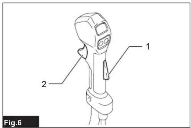
text_image
1 2 Fig.6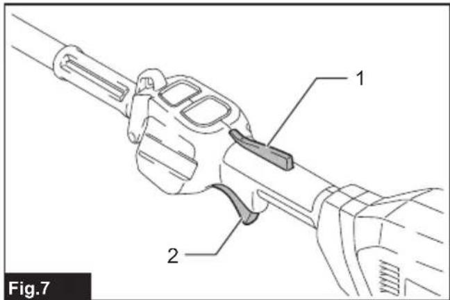
text_image
Fig.7 1 2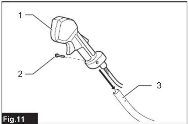
text_image
1 2 3 Fig.11
text_image
1 3 2 1 2 1 / 2 / 3 Fig.8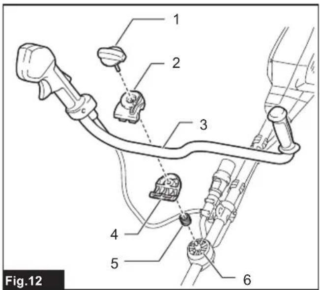
text_image
Fig.12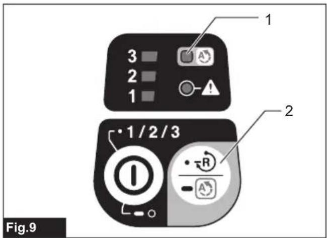
text_image
1 3 2 1 2 1 / 2 / 3 - R - A Fig.9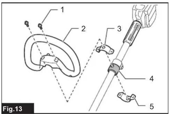
text_image
Fig.13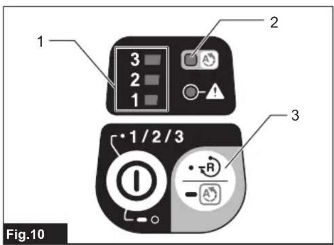
text_image
1 2 3 2 1 3 1 / 2 / 3 - R - A Fig.10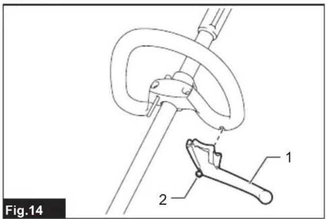
text_image
Fig.14 1 2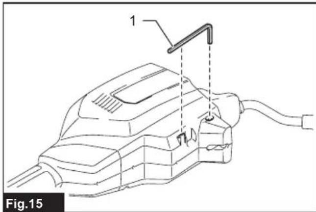
text_image
1 Fig.15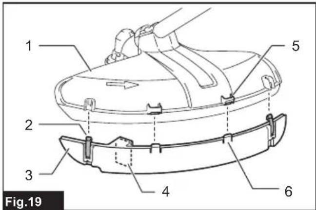
text_image
1 2 3 4 5 6 Fig.19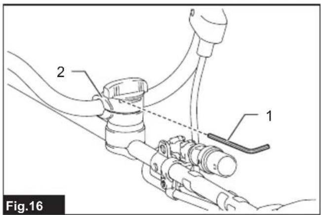
text_image
2 1 Fig.16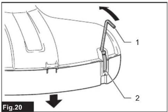
text_image
Fig.20 1 2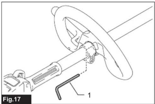
natural_image
Technical line drawing of a mechanical assembly with a lever and wheel (no text or symbols)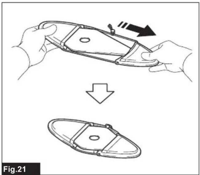
natural_image
Diagram showing two-step assembly of a mobile phone device, with no visible text or symbols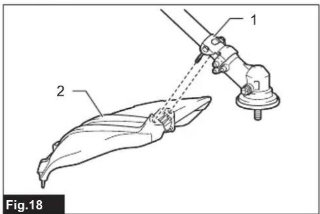
text_image
Fig.18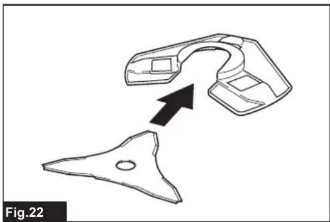
natural_image
Diagram showing a mechanical component with an arrow pointing to a triangular shape, labeled Fig.22 (no text or symbols on the diagram itself)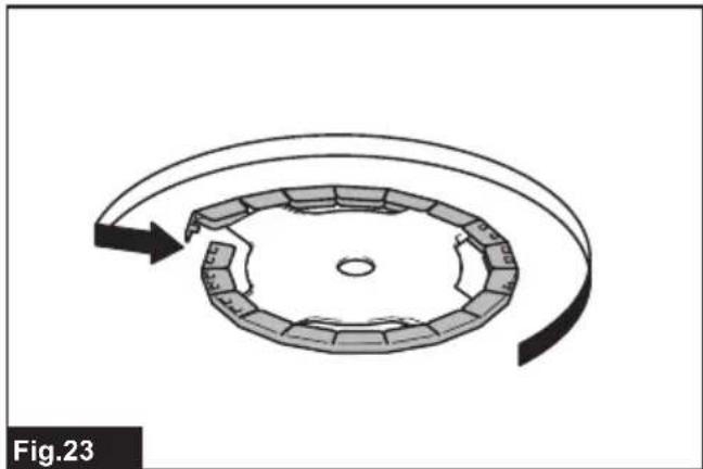
natural_image
Diagram of a circular mechanical component with internal segments and directional arrows, labeled Fig.23 (no text or symbols on the diagram itself)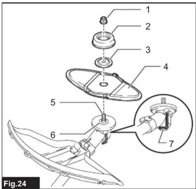
text_image
Fig.24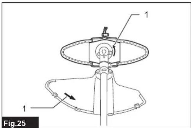
text_image
1 1 Fig.25
text_image
1 4 3 2 Fig.26
text_image
Fig.27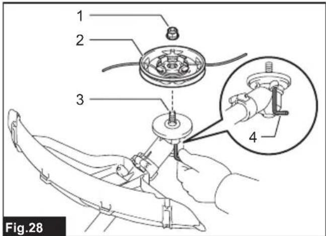
text_image
1 2 3 4 Fig.28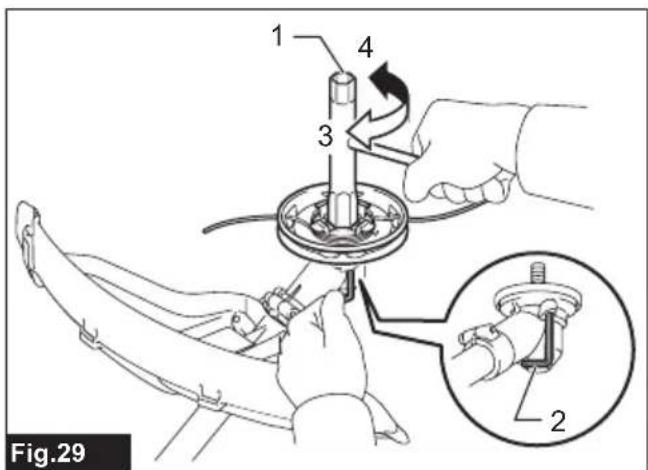
text_image
Fig.29 1 4 3 2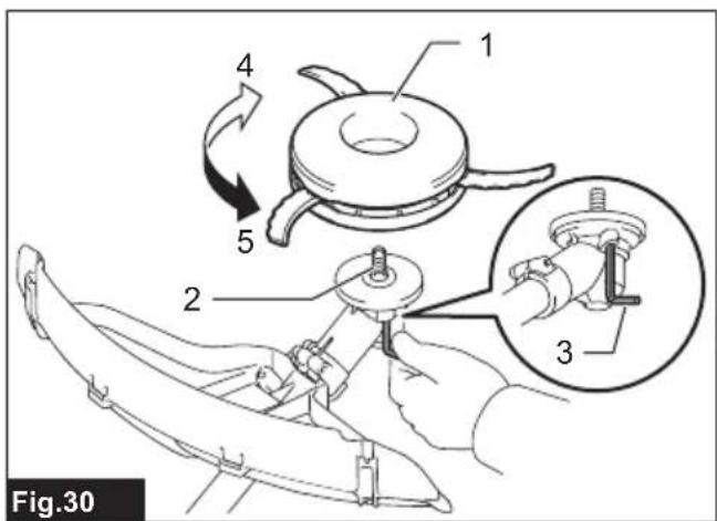
text_image
Fig.30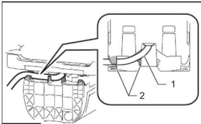
text_image
Technical diagram showing a mechanical assembly with labeled parts 1 and 2, including a magnified inset view.Fig.31
natural_image
Line drawing of a person wearing a full-body safety harness (no text or symbols)Fig.34
text_image
Fig.32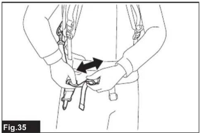
natural_image
Line drawing of a person adjusting a harness with a belt, showing two hands and a double-headed arrow indicating motion (no text or symbols)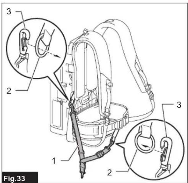
text_image
Fig.33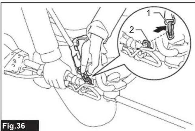
text_image
Fig.36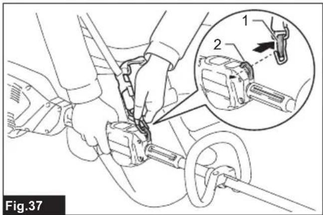
text_image
Fig.37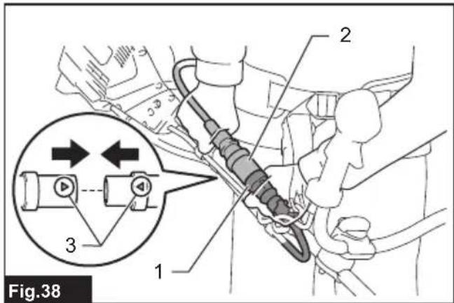
text_image
Fig.38 1 2 3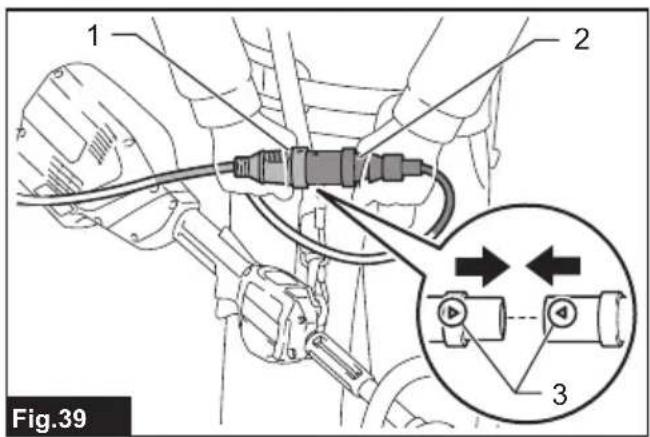
text_image
1 2 3 Fig.39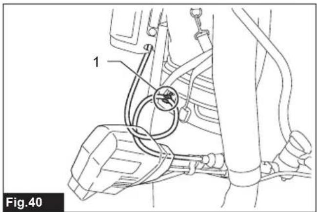
text_image
1 Fig.40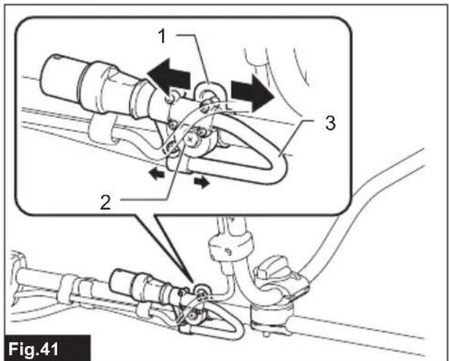
text_image
1 2 3 Fig.41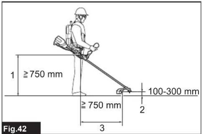
text_image
1 ≥750 mm ≥750 mm 3 2 100-300 mm Fig.42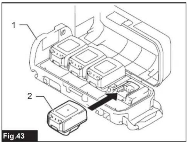
text_image
1 2 Fig.43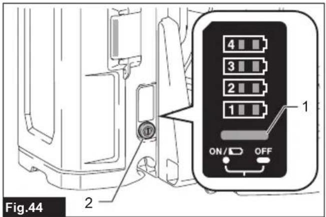
text_image
Fig.44 2 1 4 3 2 1 ON/ OFF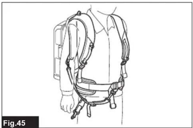
natural_image
Line drawing of a person wearing a multi-legged backpack with straps and straps (no text or symbols)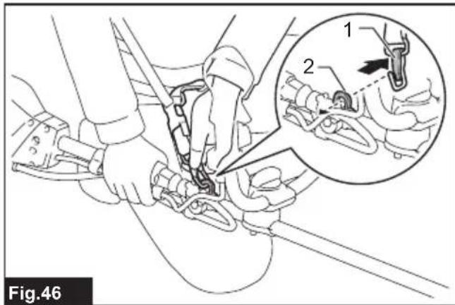
text_image
Fig.46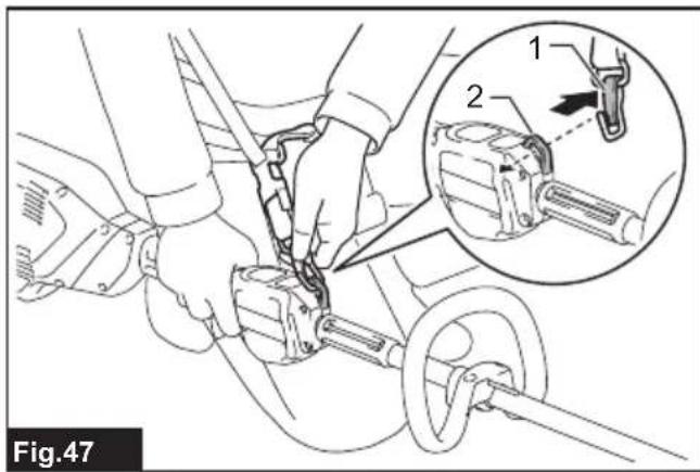
text_image
Fig.47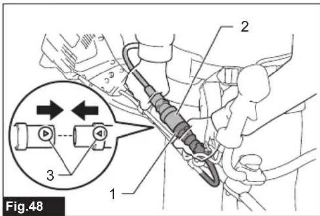
text_image
Fig.48 1 2 3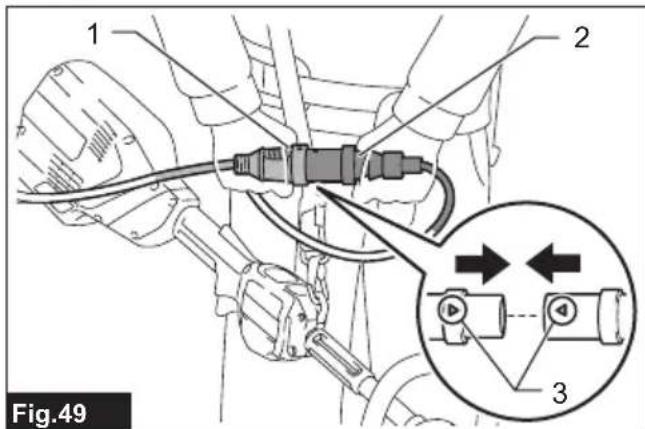
text_image
1 2 3 Fig.49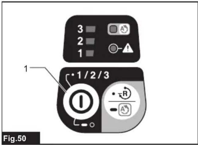
text_image
3 2 1 1 / 2 / 3 - R - A Fig.50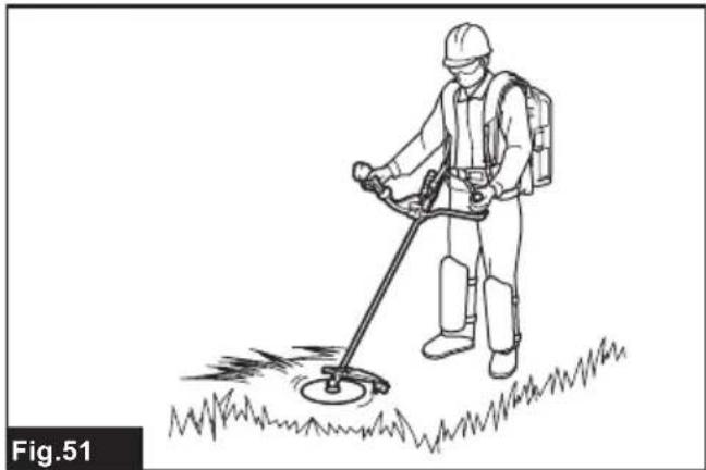
natural_image
Line drawing of a person in protective gear using a metal detector on grass (no text or symbols)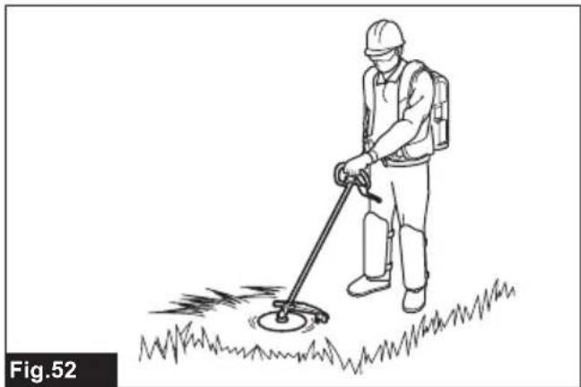
natural_image
Line drawing of a person using a handheld metal detector on grass (no text or symbols)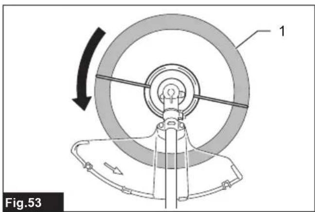
natural_image
Mechanical diagram of a rotating wheel assembly with labeled component 1, showing rotational motion (no text or symbols beyond label)
text_image
Fig.54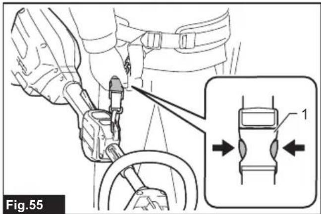
text_image
Fig.55 1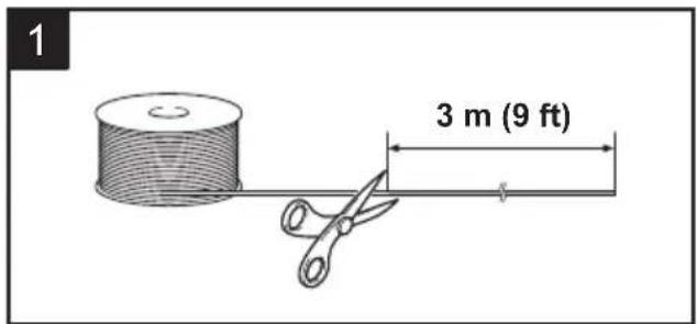
text_image
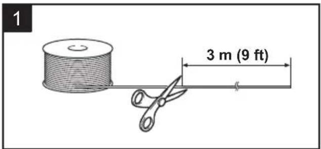
1 3 m (9 ft)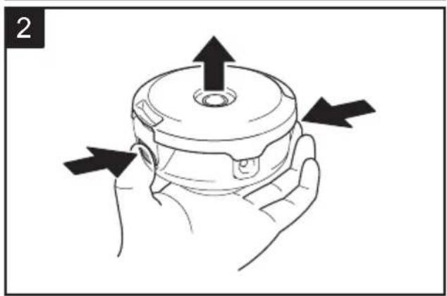
natural_image
Illustration of a hand holding a small mechanical component with arrows indicating direction (no text or symbols)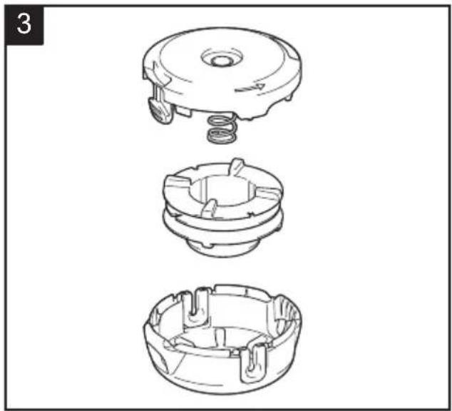
natural_image
Three technical line drawings of mechanical components, showing exploded and assembled views (no text or symbols)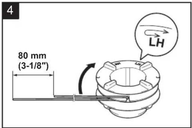
text_image
80 mm (3-1/8") LH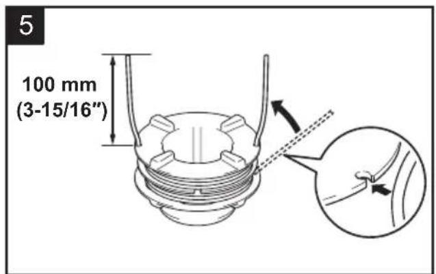
text_image
5 100 mm (3-15/16")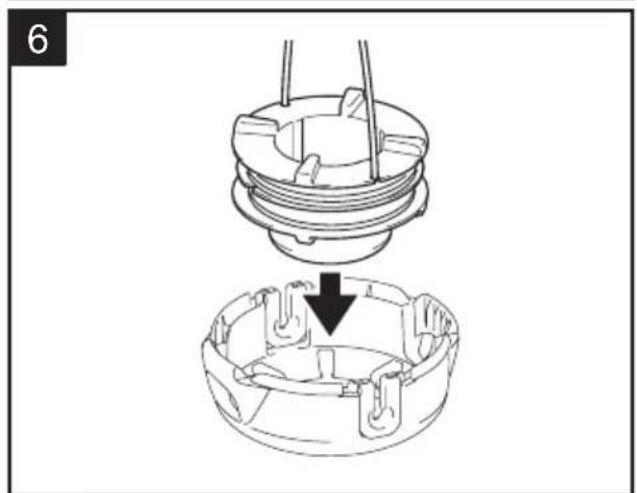
natural_image
Technical line drawing of a mechanical component with a downward arrow indicating assembly or disassembly (no text or symbols present)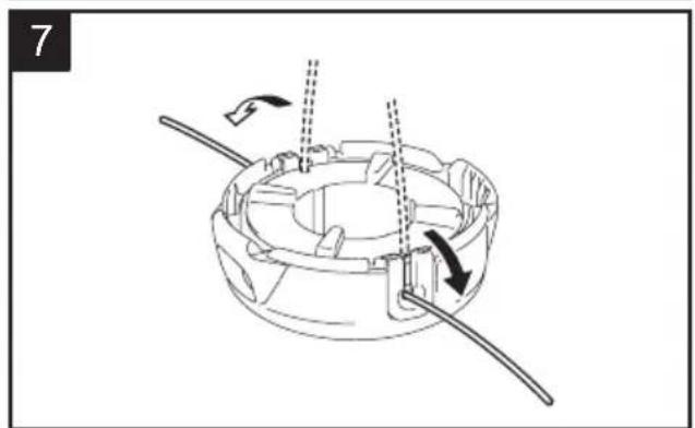
natural_image
Mechanical assembly diagram showing a circular component with internal parts and two directional arrows indicating motion (no text or symbols)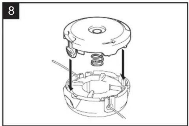
natural_image
Technical line drawing of a mechanical clutch assembly with internal components and arrows indicating motion (no text or symbols)Fig.56
text_image
1 3 m (9 ft) s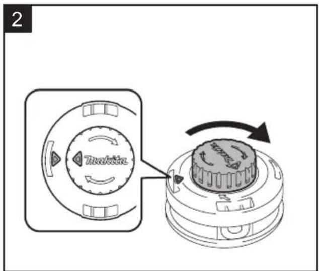
text_image
2 Tuckita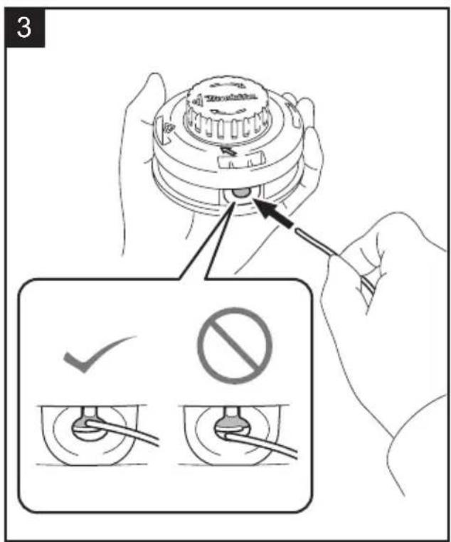
text_image
3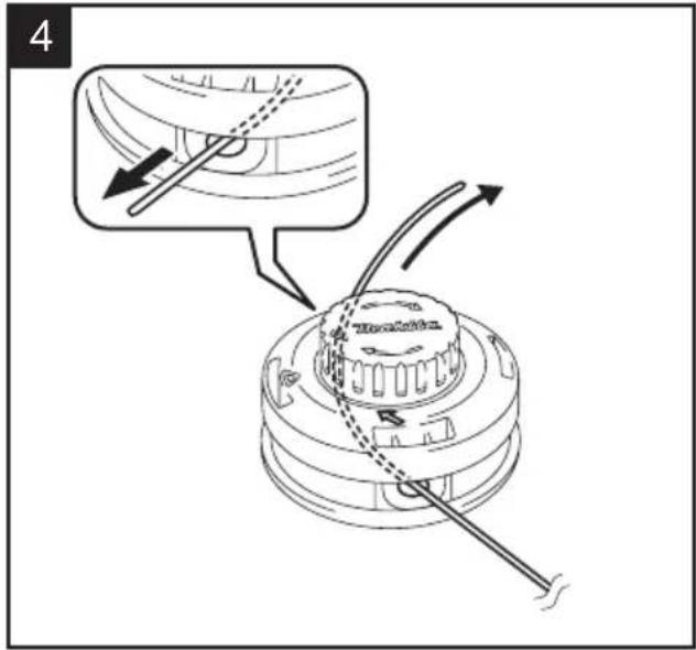
text_image
4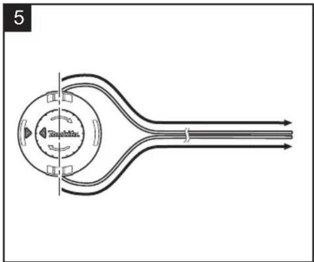
natural_image
Pure diagram of a symmetrical electrical or mechanical component with no text, numbers, or symbols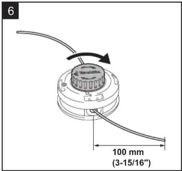
text_image
6 100 mm (3-15/16'')Fig.57
text_image
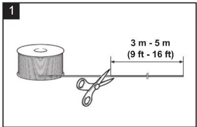
1 3 m - 5 m (9 ft - 16 ft)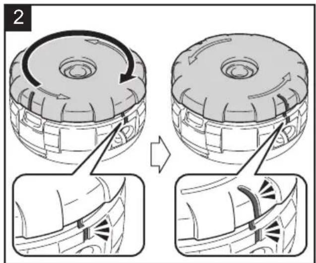
text_image
2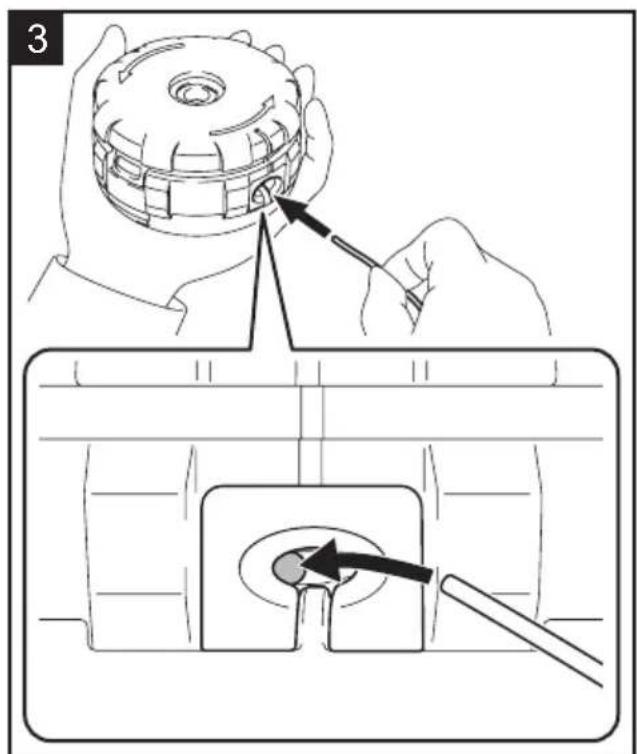
text_image
3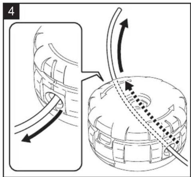
text_image
4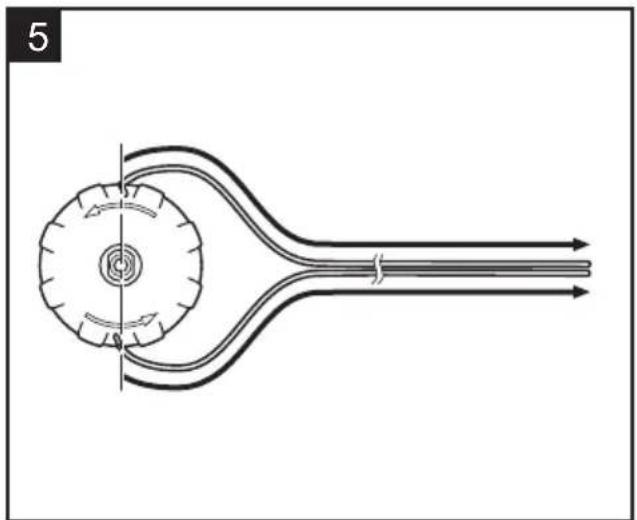
natural_image
Diagram of a symmetrical electrical or mechanical component with curved and straight lines, no text or symbols present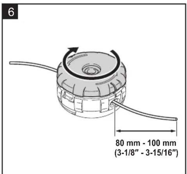
text_image
6 80 mm - 100 mm (3-1/8" - 3-15/16")Fig.58
text_image
1 3 m (9 ft)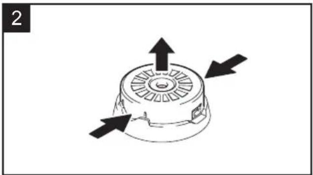
natural_image
Diagram of a mechanical component with directional arrows indicating motion or force (no text or symbols)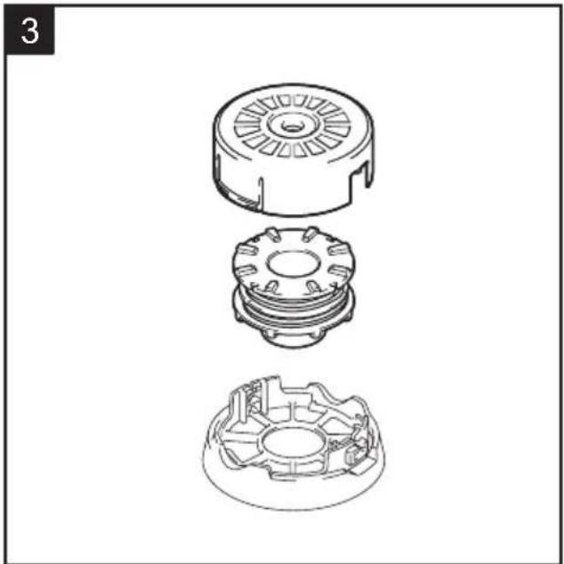
natural_image
Technical line drawing of a mechanical component showing three views: top view, front view, and side view (no text or symbols)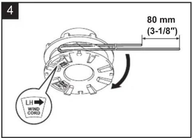
text_image
4 80 mm (3-1/8") LH WIND CORD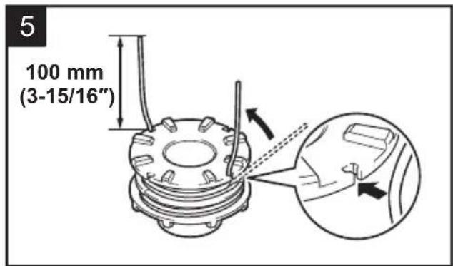
text_image
5 100 mm (3-15/16")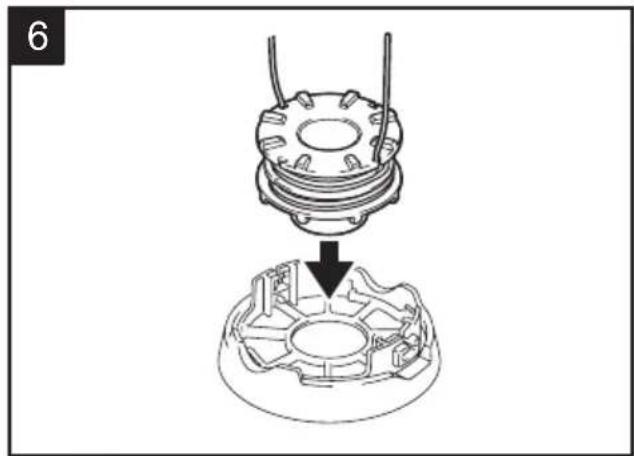
natural_image
Technical line drawing of a mechanical assembly with a clamping device above a housing (no text or symbols)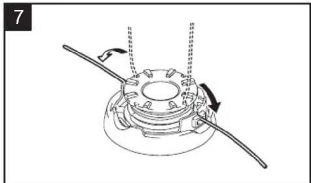
natural_image
Mechanical assembly diagram showing a rotating component with two curved rods and a central hub (no text or symbols)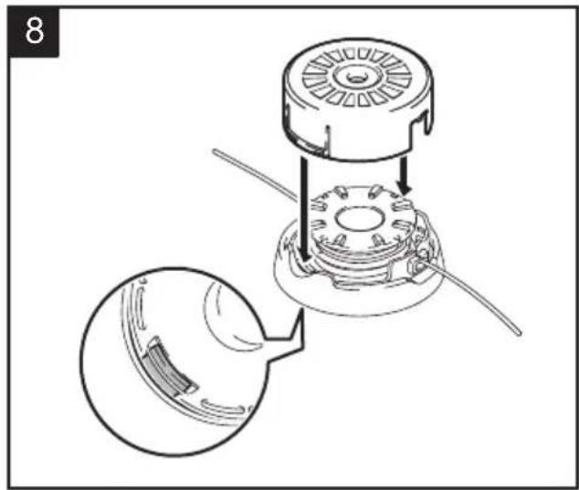
natural_image
Technical diagram of a mechanical assembly with internal components and a magnified view (no text or symbols)Fig.59
text_image
4.5 m (15 ft)
text_image
Diagram illustrating a curved pipe being twisted, with arrows indicating the process and a dashed line at the bottom.↓
text_image
Technical diagram showing mechanical assembly steps with crosshair and checkmark indicators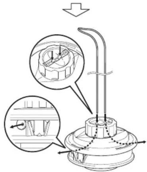
text_image
Technical diagram illustrating mechanical assembly with labeled components and directional arrows, including a magnified inset of a gear mechanism.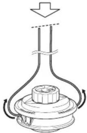
natural_image
Diagram of a laboratory setup with a Bunsen burner, tubing, and a downward arrow indicating flow (no text or labels)↓
natural_image
Technical line drawing of a mechanical component with directional arrows indicating flow or movement (no text or symbols)↓
text_image
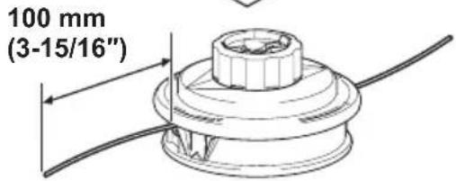
100 mm (3-15/16")Fig.60
text_image
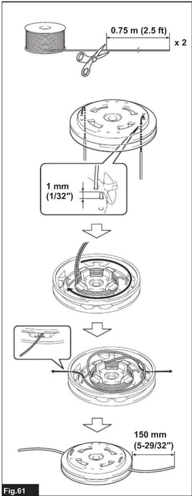
0.75 m (2.5 ft) x 2 1 mm (1/32") 150 mm (5-29/32") Fig.61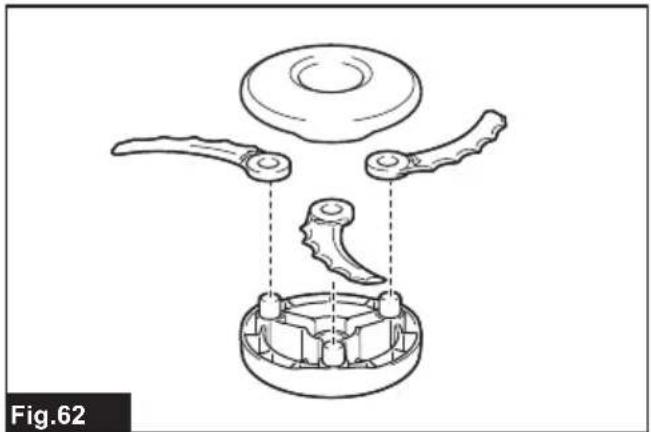
natural_image
Technical line drawing of a mechanical assembly with three components and a base plate (no text or symbols)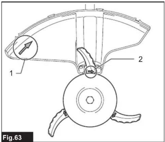
text_image
1 2 Fig.63SPECIFICATIONS
| Model: UR101C UR201C | |||
| Handle type Bike handle Loop handle | |||
| No load speed (at each rotation speed level) | Cutter blade Plastic blade (305 mm) | 3: 0 - 7,000 min ^-1 2: 0 - 5,500 min ^-1 1: 0 - 4,600 min ^-1 | |
| Nylon cutting head Plastic blade (255 mm) | 3: 0 - 5,500 min ^-1 2: 0 - 5,000 min ^-1 1: 0 - 4,600 min ^-1 | ||
| Overall length (without cutting tool) | 1,760 mm 1,795 mm | ||
| Nylon cord diameter 2.4 mm | |||
| Applicable cutting tool and cutting diameter | 2-tooth blade (P/N 198345-9) | 255 mm | |
| 3-tooth blade (P/N 195299-1) | 255 mm | ||
| 4-tooth blade (P/N 196895-8) | 255 mm | ||
| Nylon cutting head (P/N 197993-1 / 191D90-9 / 1915D7-6) | 430 mm | ||
| Plastic blade (P/N 198383-1) (P/N 199868-0) | 255 mm305 mm | ||
| Rated voltage D.C. 36 V - 40 V max | |||
| Net weight 5.2 kg 4.7 kg | |||
| Protection degree IPX4 | |||
- Due to our continuing program of research and development, the specifications herein are subject to change without notice.
- Specifications may differ from country to country.
• Weight according to EPTA-Procedure 01/2014
Recommended cord connected power source
| Portable power pack PDC01 / PDC1200 / PDC1500 |
- The cord connected power source(s) listed above may not be available depending on your region of residence.
- Before using the cord connected power source, read instruction and cautionary markings on them.
Noise
Model UR101C
| Cutting tool Sound pressure level (L _pA ) dB(A) | Sound power level ( L_WA ) dB(A) | Applicable standard | |||
| L_pA dB(A) | Uncertainty (K) dB(A) | ||||
| 2-tooth blade | 81.7 | 0.5 | 93.9 | 0.8 | ISO22868(ISO11806-1) |
| 4-tooth blade | 83.0 | 0.3 | 97.6 | 0.2 | ISO22868(ISO11806-1) |
| Nylon cutting head | 80.0 | 0.9 | 91.8 | 1.0 | ISO22868(ISO11806-1)/ EN50636-2-91 |
| Plastic blade | 78.0 | 1.0 | 87.4 | 0.7 | ISO22868(ISO11806-1)/ EN50636-2-91 |
Model UR201C
| Cutting tool Sound pressure level (L _pA ) dB(A) | Sound power level (L _WA ) dB(A) | Applicable standard | ||
| L _pA dB(A) | Uncertainty (K) dB(A) | L _WA dB(A) | Uncertainty (K) dB(A) | |
| 2-tooth blade 81.7 0.5 | 93.9 0.8 ISO22868(ISO11806-1) | |||
| 4-tooth blade 83.0 0.3 | 97.6 0.2 ISO22868(ISO11806-1) | |||
| Nylon cutting head 80 | 0 0.9 91.8 1.0 ISO22868(ISO11806-1)/ | EN50636-2-91 | ||
| Plastic blade 78.0 1.0 | 87.4 0.7 ISO22868(ISO11806-1)/ | EN50636-2-91 | ||
- Even if the sound pressure level listed above is 80 dB (A) or less, the level under working may exceed 80 dB (A). Wear ear protection.
NOTE: The declared noise emission value(s) has been measured in accordance with a standard test method and may be used for comparing one tool with another.
NOTE: The declared noise emission value(s) may also be used in a preliminary assessment of exposure.
WARNING: Wear ear protection.
⚠ WARNING: The noise emission during actual use of the power tool can differ from the declared value(s) depending on the ways in which the tool is used especially what kind of workpiece is processed.
WARNING: Be sure to identify safety measures to protect the operator that are based on an estimation of exposure in the actual conditions of use (taking account of all parts of the operating cycle such as the times when the tool is switched off and when it is running idle in addition to the trigger time).
Vibration
Applicable standard : ISO22867(ISO11806-1)
Model UR101C
| Cutting tool Left hand Right hand | ||||
| a_h,w (m/s^2) Uncertainty K ( m/s^2 ) | a_h,w (m/s^2) Uncertainty K ( m/s^2 ) | |||
| 2-tooth blade | ≤ 2.5 | 1.5 | ≤ 2.5 | 1.5 |
| 4-tooth blade | ≤ 2.5 | 1.5 | ≤ 2.5 | 1.5 |
| Nylon cutting head | ≤ 2.5 | 1.5 | ≤ 2.5 | 1.5 |
| Plastic blade | ≤ 2.5 | 1.5 | ≤ 2.5 | 1.5 |
Model UR201C
| Cutting tool Left hand Right hand | ||||
| a_h,w (m/s^2) Uncertainty K ( m/s^2 ) | a_h,w (m/s^2) Uncertainty K ( m/s^2 ) | |||
| 2-tooth blade | ≤ 2.5 | 1.5 | ≤ 2.5 | 1.5 |
| 4-tooth blade | ≤ 2.5 | 1.5 | ≤ 2.5 | 1.5 |
| Nylon cutting head | ≤ 2.5 | 1.5 | ≤ 2.5 | 1.5 |
| Plastic blade | ≤ 2.5 | 1.5 | ≤ 2.5 | 1.5 |
NOTE: The declared vibration total value(s) has been measured in accordance with a standard test method and may be used for comparing one tool with another.
NOTE: The declared vibration total value(s) may also be used in a preliminary assessment of exposure.
⚠ WARNING: The vibration emission during actual use of the power tool can differ from the declared value(s) depending on the ways in which the tool is used especially what kind of workpiece is processed.
WARNING: Be sure to identify safety measures to protect the operator that are based on an estimation of exposure in the actual conditions of use (taking account of all parts of the operating cycle such as the times when the tool is switched off and when it is running idle in addition to the trigger time).
Symbols
The followings show the symbols which may be used for the equipment. Be sure that you understand their meaning before use.

Take particular care and attention.


Read instruction manual.
Keep distance at least 15 m.
| Danger; be aware of thrown objects. | |
| Caution; kickback | |
| Wear a helmet, goggles and ear protection. | |
| Wear protective gloves. | |
| Wear sturdy boots with nonslip soles.Steeltoed safety boots are recommended. | |
| Only for EU countriesDue to the presence of hazardous components in the equipment, waste electrical and electronic equipment, accumulators and batteries may have a negative impact on the environment and human health.Do not dispose of electrical and electronic appliances or batteries with household waste!In accordance with the European Directive on waste electrical and electronic equipment and on accumulators and batteries and waste accumulators and batteries, as well as their adaptation to national law, waste electrical equipment, batteries and accumulators should be stored separately and delivered to a separate collection point for municipal waste, operating in accordance with the regulations on environmental protection.This is indicated by the symbol of the crossed-out wheeled bin placed on the equipment. | |
 | Guaranteed sound power level according to EU Outdoor Noise Directive. |
 | Sound power level according to Australia NSW Noise Control Regulation. |
Declarations of Conformity
For European countries only
The Declarations of conformity are included in Annex A to this instruction manual.
SAFETY WARNINGS
General power tool safety warnings
WARNING Read all safety warnings, instructions, illustrations and specifications provided with this power tool. Failure to follow all instructions listed below may result in electric shock, fire and/or serious injury.
Save all warnings and instructions for future reference.
The term "power tool" in the warnings refers to your mains-operated (corded) power tool or battery-operated (cordless) power tool.
Important safety instructions for the tool
WARNING: Be sure to thoroughly read and understand this instruction manual as well as the instruction manual of the portable power pack to be used with this tool. Failure to follow the warnings and instructions may result in electric shock, fire and/or serious injury.
WARNING: Read all safety warnings and all instructions. Failure to follow the warnings and instructions may result in electric shock, fire and/or serious injury.
Save all warnings and instructions for future reference.
Intended use
- This tool is only intended for cutting grass, weeds, bushes and undergrowth. It should not be used for any other purpose such as edging or hedge cutting as this may cause injury.
General instructions
- Never allow people unfamiliar with these instructions, people (including children) with reduced physical, sensory or mental capabilities, or lack of experience and knowledge to use the tool. Children should be supervised to ensure that they do not play with the tool.
- Before starting the tool, read this instruction manual to become familiar with the handling of the tool.
- Do not lend the tool to a person with insufficient experience or knowledge regarding handling of brushcutters and string trimmers.
- When lending the tool, always attach this instruction manual.
- Handle the tool with the utmost care and attention.
- Never use the tool after consuming alcohol or drugs, or if feeling tired or ill.
- Never attempt to modify the tool.
- Follow the regulations about handling of brushcutters and string trimmers in your country.
Personal protective equipment
▶ Fig.1
- Wear safety helmet, protective goggles and protective gloves to protect yourself from flying debris or falling objects.
- Wear ear protection such as ear muffs to prevent hearing loss.
- Wear proper clothing and shoes for safe operation, such as a work overall and sturdy, non-slip shoes. Do not wear loose clothing or jewelry. Loose clothes, jewelry or long hair can be caught in moving parts.
- When touching the cutting blade, wear protective gloves. Cutting blades can cut bare hands
severely.
Work area safety
- Operate the tool under good visibility and daylight conditions only. Do not operate the tool in darkness or fog.
- Do not operate the tool in explosive atmospheres, such as in the presence of flammable liquids, gases or dust. The tool creates sparks which may ignite the dust or fumes.
- During operation, never stand on an unstable or slippery surface or a steep slope. During the cold season, beware of ice and snow and always ensure secure footing.
- During operation, keep bystanders or animals at least 15 m away from the tool. Stop the tool as soon as someone approaches.
- Never operate the tool while people, especially children, or pets are nearby.
- Before operation, examine the work area for stones or other solid objects. They can be thrown or cause dangerous kickback and result in serious injury and/or property damage.
- ⚠WARNING: Use of this product can create dust containing chemicals which may cause respiratory or other illnesses. Some examples of these chemicals are compounds found in pesticides, insecticides, fertilizers and herbicides. Your risk from these exposures varies, depending on how often you do this type of work. To reduce your exposure to these chemicals: work in a well ventilated area, and work with approved safety equipment, such as those dust masks that are specially designed to filter out microscopic particles.
Electrical and battery safety
- Do not expose the tool to rain or wet conditions. Water entering the tool will increase the risk of electric shock.
- Do not use the tool if the switch does not turn it on and off. Any tool that cannot be controlled with the switch is dangerous and must be repaired.
- Prevent unintentional starting. Ensure the switch is in the off-position before picking up or carrying the tool. Carrying the tool with your finger on the switch or energising the tool that have the switch on invites accidents.
- Do not dispose of the battery(ies) in a fire. The cell may explode. Check with local codes for possible special disposal instructions.
- Do not open or mutilate the battery(ies). Released electrolyte is corrosive and may cause damage to the eyes or skin. It may be toxic if swallowed.
- Do not charge battery in rain, or in wet locations.
- Do not replace the battery with wet hands.
- Do not replace the battery in the rain.
- Do not wet the terminal of battery with liquid such as water, or submerge the battery. Do not leave the battery in the rain, nor charge, use, or store the battery in a damp or wet place. If
the terminal gets wet or liquid enters inside of battery, the battery may be short circuited and there is a risk of overheat, fire, or explosion.
-
Do not connect/disconnect the plug to/from the socket of the portable power pack in the rain or wet conditions. Do not leave, use, or store the tool and portable power pack in the rain or a damp or wet place. Doing so may cause electric shock.
-
After removing the battery from the portable power pack or charger, be sure to attach the battery cover to the battery and store it in a dry place.
-
If the battery cartridge gets wet, drain the water inside and then wipe it with a dry cloth. Dry the battery cartridge completely in a dry place before use.
Putting into operation
- Before assembling or adjusting the tool, disconnect the portable power pack from the tool.
- Before handling the cutter blade, wear protective gloves.
- Before connecting the portable power pack to the tool, inspect the tool for damages, loose screws/nuts or improper assembly. Sharpen blunt cutter blade. If the cutter blade is bent or damaged, replace it. Check all control levers and switches for easy action. Clean and dry the handles.
- Never attempt to switch on the tool if it is damaged or not fully assembled. Otherwise serious injury may result.
- Adjust the shoulder harness and hand grip to suit the operator's body size.
- When connecting the portable power pack to the tool, keep the cutting attachment clear of your body and other object, including the ground. It may rotate when starting and may cause injury or damage to the tool and/or property.
- Remove any adjusting key, wrench or blade cover before turning the tool on. An accessory left attached to a rotating part of the tool may result in personal injury.
- The cutting tool has to be equipped with the guard. Never run the tool with damaged guards or without guards in place!
- Make sure there are no electrical cables, water pipes, gas pipes etc. that could cause a hazard if damaged by use of the tool.
Operation
- In the event of an emergency, switch off the tool immediately.
- If you feel any unusual condition (e.g. noise, vibration) during operation, switch off the tool and disconnect the portable power pack from the tool. Do not use the tool until the cause is recognized and solved.
- The cutting attachment continues to rotate for a short period after turning the tool off. Don't rush to contact the cutting attachment.
-
During operation, use the shoulder harness. Keep the tool on your right side firmly.
-
Do not overreach. Keep proper footing and balance at all times. Watch for hidden obstacles such as tree stumps, roots and ditches to avoid stumbling.
- Always be sure of your footing on slopes.
- Walk, never run.
- Never work on a ladder or tree to avoid loss of control.
- If the tool gets heavy impact or fall, check the condition before continuing work. Check the controls and safety devices for malfunction. If there is any damage or doubt, ask our authorized service center for the inspection and repair.
- Do not touch the gear case during and immediately after the operation. The gear case becomes hot during operation and can cause burn injury.
- Take a rest to prevent loss of control caused by fatigue. We recommend taking a 10 to 20-minute rest every hour.
- When you leave the tool, even if it is a short time, always disconnect the portable power pack from the tool. The unattended tool with the battery cartridge installed may be used by unauthorized person and cause serious accident.
- If grass or branches get caught between the cutting attachment and guard, always turn the tool off and disconnect the portable power pack from the tool. Otherwise the cutting attachment may rotate unintentionally and cause serious injury.
- Never touch moving hazardous parts before the moving hazardous parts have come to a complete stop and the portable power pack is disconnected from the tool.
- If the cutting attachment hits stones or other hard objects, immediately turn the tool off. Then disconnect the portable power pack from the tool and inspect the cutting attachment.
- Check the cutting attachment frequently during operation for cracks or damages. Before the inspection, disconnect the portable power pack from the tool and make sure that the cutting attachment stops completely. Replace damaged cutting attachment immediately, even if it has only superficial cracks.
- Never cut above waist height.
- Before starting the cutting operation, wait until the cutting attachment reaches a constant speed after turning the tool on.
- When using a cutting blade, swing the tool evenly in half-circle from right to left, like using a scythe.
- Hold the tool by insulated gripping surfaces only, because the cutter blade may contact hidden wiring. Cutter blades contacting a "live" wire may make exposed metal parts of the tool "live" and could give the operator an electric shock.
- Do not start the tool when the cutting tool is tangled with cut grass.
- Before starting the tool, be sure that the cutting tool is not touching the ground and other
obstacles such as a tree.
- During operation always hold the tool with both hands. Never hold the tool with one hand during use.
- Do not use the tool when there is a risk of lightning.
- When you use the tool on muddy ground, wet slope, or slippery place, pay attention to your footing.
- Avoid working in poor environment where increased user fatigue is expected.
- Do not use the tool in bad weather where visibility is limited. Failure to do so may cause fall or incorrect operation due to low visibility.
- Do not submerge the tool into a puddle.
- Do not leave the tool unattended outdoors in the rain.
- When wet leaves or dirt adhere to the suction mouth (ventilation window) due to rain, remove them.
- Do not use the tool in the snow.
Cutting tools
- Do not use a cutting tool which is not recommended by Makita.
- Use an applicable cutting attachment for the job in hand.
— Nylon cutting heads (string trimmer heads) and plastic blades are suitable for trimming lawn grass.
— Cutting blades are suitable for cutting weeds, high grasses, bushes, shrubs, underwood, thicket, and the like.
— Never use other blades including metal multi-piece pivoting chains and flail blades. It may result in serious injury.
- Only use the cutting tool that are marked with a speed equal or higher than the speed marked on the tool.
- Always keep your hands, face, and clothes away from the cutting tool when it is rotating. Failure to do so may cause personal injury.
- Always use the cutting attachment guard properly suited for the cutting attachment used.
- When using cutting blades, avoid kickback and always prepare for an accidental kickback. See the section for Kickback.
- When not in use, attach the blade cover onto the blade. Remove the cover before operation.
Kickback (Blade thrust)
- Kickback (blade thrust) is a sudden reaction to a caught or bound cutting blade. Once it occurs, the tool is thrown sideway or toward the operator at great force and it may cause serious injury.
- Kickback occurs particularly when applying the blade segment between 12 and 2 o'clock to solids, bushes and trees with 3 cm or larger diameter.
▶ Fig.2
-
To avoid kickback:
-
Apply the segment between 8 and 11 o'clock.
- Never apply the segment between 12 and 2 o'clock.
- Never apply the segment between 11 and 12 o'clock and between 2 and 5 o'clock, unless the operator is well trained and experienced and does it at his/her own risk.
- Never use cutting blades close to solids, such as fences, walls, tree trunks and stones.
- Never use cutting blades vertically, for such operations as edging and trimming hedges.
▶ Fig.3
Vibration
- People with poor circulation who are exposed to excessive vibration may experience injury to blood vessels or the nervous system. Vibration may cause the following symptoms to occur in the fingers, hands or wrists: "Falling asleep" (numbness), tingling, pain, stabbing sensation, alteration of skin color or of the skin. If any of these symptoms occur, see a physician!
- To reduce the risk of "white finger disease", keep your hands warm during operation and well maintain the tool and accessories.
Transport
- Before transporting the tool, turn it off and disconnect the portable power pack from the tool. Attach the cover to the cutting blade.
- When transporting the tool, carry it in a horizontal position by holding the shaft.
- When transporting the tool in a vehicle, properly secure it to avoid turnover. Otherwise damage to the tool and other baggage may result.
Maintenance
- Have your tool serviced by our authorized service center, always using only genuine replacement parts. Incorrect repair and poor maintenance can shorten the life of the tool and increase the risk of accidents.
- Before doing any maintenance or repair work or cleaning the tool, always turn it off and disconnect the portable power pack from the tool.
- Always wear protective gloves when handling the cutting blade.
- Always clean dust and dirt off the tool. Never use gasoline, benzine, thinner, alcohol or the like for the purpose. Discoloration, deformation or cracks of the plastic components may result.
- After each use, tighten all screws and nuts.
- Do not attempt any maintenance or repair not described in the instruction manual. Ask our authorized service center for such work.
- Always use our genuine spare parts and accessories only. Using parts or accessories supplied by a third party may result in the tool
breakdown, property damage and/or serious injury.
- Request our authorized service center to inspect and maintain the tool at regular interval.
- Always keep the tool in good working condition. Poor maintenance can result in inferior performance and shorten the life of the tool.
- Do not wash the tool with high pressure water.
- When washing the tool, do not let water enter the electrical mechanism such as motor and terminals.
- When storing the tool, avoid direct sunlight and rain, and store it in a place where it does not get hot or humid.
- Perform inspection or maintenance in a place where rain can be avoided.
- After using the tool, remove the adhered dirt and dry the tool completely before storing. Depending on the season or the area, there is a risk of malfunction due to freezing.
- Keep all cooling air inlets clear of debris.
Storage
- Before storing the tool, perform full cleaning and maintenance. Disconnect the portable power pack from the tool. Attach the cover to the cutting blade.
- Store the tool in a dry and high or locked location out of reach of children.
- Do not prop the tool against something, such as a wall. Otherwise it may fall suddenly and cause an injury.
First aid
- Always have a first-aid kit close by. Immediately replace any item taken from the first aid kit.
- When asking for help, give the following information:
— Place of the accident
— What happened
— Number of injured persons
— Nature of the injury
— Your name
Important safety instructions for battery cartridge
- Before using battery cartridge, read all instructions and cautionary markings on (1) battery charger, (2) battery, and (3) product using battery.
- Do not disassemble or tamper with the battery cartridge. It may result in a fire, excessive heat, or explosion.
- If operating time has become excessively shorter, stop operating immediately. It may result in a risk of overheating, possible burns and even an explosion.
- If electrolyte gets into your eyes, rinse them out with clear water and seek medical attention right away. It may result in loss of your
eyesight.
- Do not short the battery cartridge:
(1) Do not touch the terminals with any conductive material.
(2) Avoid storing battery cartridge in a container with other metal objects such as nails, coins, etc.
(3) Do not expose battery cartridge to water or rain.
A battery short can cause a large current flow, overheating, possible burns and even a breakdown.
- Do not store and use the tool and battery cartridge in locations where the temperature may reach or exceed 50 °C (122 °F).
- Do not incinerate the battery cartridge even if it is severely damaged or is completely worn out. The battery cartridge can explode in a fire.
- Do not nail, cut, crush, throw, drop the battery cartridge, or hit against a hard object to the battery cartridge. Such conduct may result in a fire, excessive heat, or explosion.
- Do not use a damaged battery.
- The contained lithium-ion batteries are subject to the Dangerous Goods Legislation requirements.
For commercial transports e.g. by third parties, forwarding agents, special requirement on packaging and labeling must be observed.
For preparation of the item being shipped, consulting an expert for hazardous material is required. Please also observe possibly more detailed national regulations.
Tape or mask off open contacts and pack up the battery in such a manner that it cannot move around in the packaging.
- When disposing the battery cartridge, remove it from the tool and dispose of it in a safe place. Follow your local regulations relating to disposal of battery.
- Use the batteries only with the products specified by Makita. Installing the batteries to non-compliant products may result in a fire, excessive heat, explosion, or leak of electrolyte.
-
If the tool is not used for a long period of time, the battery must be removed from the tool.
-
During and after use, the battery cartridge may take on heat which can cause burns or low temperature burns. Pay attention to the handling of hot battery cartridges.
- Do not touch the terminal of the tool immediately after use as it may get hot enough to cause burns.
- Do not allow chips, dust, or soil stuck into the terminals, holes, and grooves of the battery cartridge. It may cause heating, catching fire, burst and malfunction of the tool or battery cartridge, resulting in burns or personal injury.
- Unless the tool supports the use near high-voltage electrical power lines, do not use the battery cartridge near high-voltage electrical power lines. It may result in a malfunction or breakdown of the tool or battery cartridge.
- Keep the battery away from children.
SAVE THESE INSTRUCTIONS.
CAUTION: Only use genuine Makita batteries. Use of non-genuine Makita batteries, or batteries that have been altered, may result in the battery bursting causing fires, personal injury and damage. It will also void the Makita warranty for the Makita tool and charger.
Tips for maintaining maximum battery life
- Charge the battery cartridge before completely discharged. Always stop tool operation and charge the battery cartridge when you notice less tool power.
- Never recharge a fully charged battery cartridge. Overcharging shortens the battery service life.
- Charge the battery cartridge with room temperature at 10 °C - 40 °C ( 50 °F - 104 °F ). Let a hot battery cartridge cool down before charging it.
- When not using the battery cartridge, remove it from the tool or the charger.
- Charge the battery cartridge if you do not use it for a long period (more than six months).
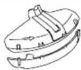
PARTS DESCRIPTION
▶ Fig.4
| 1 Speed indicator 2 ADT indicator | (ADT = Automatic Torque Drive Technology) | 3 Caution lamp 4 Main power button | |||||
| 5 | Reverse button | 6 | Plug | 7 | Lock-off lever | 8 | Switch trigger |
| 9 | Hanger | 10 | Handle | 11 | Barrier | 12 | Knob |
| 13 | Protector | 14 | Protector extension (for nylon cutting head / plastic blade) | 15 | Hanging band | - | - |
FUNCTIONAL DESCRIPTION
WARNING: Always be sure that the tool is switched off and the portable power pack is disconnected from the tool before adjusting or checking function on the tool. Failure to switch off and disconnect the portable power pack may result in serious personal injury from accidental start-up.
Tool / battery protection system
The tool is equipped with a tool/battery protection system. This system automatically cuts off power to the motor to extend tool and battery life. The tool will automatically stop during operation if the tool is placed under one of the following conditions:
| Caution lamp Status | ||
| Color |  | |
| Green | ### | Overload |
| Red |  | Overheat |
| Red | ### | Overdischarge |
Overload protection
If the tool gets into one of the following situation, the tool automatically stops and the caution lamp starts blinking in green:
— The tool is overloaded by entangled weeds or other debris.
— The cutting tool is locked or kicked back.
— The main power button is turned on while the switch trigger is being pulled.
In this situation, release the switch trigger and remove entangled weeds or debris if necessary. After that, pull the switch trigger again to resume.
⚠CAUTION: If you need to remove the entangled weeds on the tool or release the locked cutting tool, be sure to turn the tool off before you start.
Overheat protection for tool or battery
If the tool or battery cartridge is overheated, the tool stops automatically. When the tool is overheated, the caution lamp lights up in red. When the battery cartridge is overheated, the caution lamp blinks in red. Let the tool and/or battery cool down before turning the tool on again.
Overdischarge protection
When the battery capacity becomes low, the tool stops automatically and the caution lamp starts blinking in red. If the tool does not operate even when the switches are operated, remove the battery cartridge from the tool and charge it.
Main power switch
Tap the main power button to turn on the tool. To turn off the tool, press and hold the main power button until the speed indicator goes off.
▶ Fig.5: 1. Speed indicator 2. Main power button
NOTE: The tool will automatically turned off if it is left without any operations for a certain period of time.
Switch action
WARNING: For your safety, this tool is equipped with lock-off lever which prevents the tool from unintended starting. NEVER use the tool if it runs when you simply pull the switch trigger without pressing the lock-off lever. Return the tool to our authorized service center for proper repairs BEFORE further usage.
WARNING: NEVER tape down or defeat purpose and function of lock-off lever.
CAUTION: Before connecting the portable power pack to the tool, always check to see that the switch trigger actuates properly and returns to the "OFF" position when released. Operating a tool with a switch that does not actuate properly can lead to loss of control and serious personal injury.
CAUTION: Never put your finger on the main power button and switch trigger when carrying the tool. The tool may start unintentionally and cause injury.
NOTICE: Do not pull the switch trigger hard without pressing the lock-off lever. This can cause switch breakage.
To prevent the switch trigger from being accidentally pulled, a lock-off lever is provided. To start the tool, depress the lock-off lever and pull the switch trigger. The tool speed increases by increasing pressure on the switch trigger. Release the switch trigger to stop.
UR101C
▶ Fig.6: 1. Lock-off lever 2. Switch trigger
UR201C
▶ Fig.7: 1. Lock-off lever 2. Switch trigger
Speed adjusting
You can select the tool speed by tapping the main power button. Each time you tap the main power button, the level of speed will change. The tool automatically adjusts the rotation speed according to the cutting tool attached to the tool.
▶ Fig.8: 1. Speed indicator 2. Main power button
| Speed indicator | Mode Rotation speed | ||
| 321 | High 0 - 7,000 min ^-1 | 0 - 5,500 min ^-1 | |
| 321 | Medium 0 - 5,500 min ^-1 | 0 - 5,000 min ^-1 | |
| 321 | Low 0 - 4,600 min ^-1 | 0 - 4,600 min ^-1 | |
Automatic Torque Drive Technology
When you turn on the Automatic Torque Drive
Technology (ADT), the tool runs at optimum rotation
speed and torque for the condition of grass being cut.
The tool automatically detects the cutting tool attached and chooses a suitable rotation speed.
To start ADT, press and hold the reverse button until the ADT indicator turns on.
To stop ADT, press and hold the reverse button until the ADT indicator turns off.
▶ Fig.9: 1. ADT indicator 2. Reverse button
| Indicator Mode Cutting tool | Rotation | speed |
| ADT Cutter bladePlastic blade(305 mm) | 3,500 - 7,000 min^-1 | |
| Nylon cuttingheadPlastic blade(255 mm) | 3,500 - 5,500 min^-1 |
Reverse button for debris removal
⚠ WARNING: Switch off the tool and disconnect the portable power pack from the tool before you remove entangled weeds or debris which the reverse rotation function can not remove. Failure to do so may result in serious personal injury from accidental start-up.
This tool has a reverse button to change the direction of rotation. It is only for removing weeds and debris entangled in the tool.
To reverse the rotation, tap the reverse button and pull the switch trigger while depressing the lock-off lever when the cutting tool is stopped. The speed indicators and ADT indicator start blinking, and the cutting tool rotates in reverse direction when you pull the switch trigger.
To return to regular rotation, release the trigger and wait until the cutting tool stops.
▶ Fig.10: 1. Speed indicator 2. ADT indicator
- Reverse button
NOTE: During the reverse rotation, the tool operates only for a short period of time and then automatically stops.
NOTE: Once the tool is stopped, the rotation returns to regular direction when you start the tool again.
NOTE: If you tap the reverse button while the cutting tool is still rotating, the tool comes to stop and to be ready for reverse rotation.
Electric brake
This tool is equipped with an electric brake. If the tool consistently fails to quickly stop after the switch trigger is released, have the tool serviced at our service center.
CAUTION: This brake system is not a substitute for the protector. Never use the tool without the protector. An unguarded cutting tool may result in serious personal injury.
Electronic function
Constant speed control
The speed control function provides the constant rotation speed regardless of load conditions.
Soft start feature
Soft start because of suppressed starting shock.
ASSEMBLY
WARNING: Always be sure that the tool is switched off and the portable power pack is disconnected from the tool before carrying out any work on the tool. Failure to switch off and disconnect the portable power pack may result in serious personal injury from accidental start-up. WARNING: Never start the tool unless it is completely assembled. Operation of the tool in a partially assembled state may result in serious personal injury from accidental start-up.
Installing the handle
For UR101C
- Insert the shaft of the handle into the grip. Align the screw hole in the grip with the one in the shaft. Tighten the screw securely.
▶ Fig.11: 1. Grip 2. Screw 3. Shaft
NOTICE: Note the direction of the grip. The screw holes will not be aligned if the grip is not inserted in the correct direction.
- Place the spring onto the base.
▶ Fig.12: 1. Knob 2. Handle clamp 3. Handle
-
Handle holder 5. Spring 6. Base
-
Place the handle between the handle clamp and handle holder.
-
Temporarily attach the handle by tightening the knob, and adjust the handle position.
- Fully tighten the knob.
For UR201C
- Attach the upper and lower clamps on the damper.
- Put the handle on the upper clamp and fix it with hex socket head bolts as illustrated.
▶ Fig.13: 1. Hex socket head bolt 2. Handle 3. Upper clamp 4. Damper 5. Lower clamp
Attaching the barrier
For the loop handle model only (country specific)
If the barrier is included in your model, attach it to the handle using the screw on the barrier.
▶ Fig.14: 1. Barrier 2. Screw

CAUTION: After assembling the barrier, do not remove it. The barrier works as a safety part prevent you from contacting the cutting blade incidentally.
Hex wrench storage

CAUTION: Be careful not to leave the hex bench inserted in the tool head. It may cause any and/or damage to the tool.
When not in use, store the hex wrench as illustrated to keep it from being lost.
▶ Fig.15: 1. Hex wrench
For the bike handle model, the hex wrench can be stored on the handle clamp as illustrated.
▶ Fig.16: 1. Hex wrench 2. Handle clamp
For the loop handle model, the hex wrench can be stored on the handle as illustrated.
▶ Fig.17: 1. Hex wrench
Correct combination of the cutting tool and the protector

CAUTION: Always use the correct combination of cutting tool and the protector. A wrong combination may not protect you from the cutting tool, ing debris, and stones. It can also affect the balance of the tool and result in an injury.
Cutting tool Protecto
Cutter blade
(2-tooth, 3-tooth, 4-tooth blades)

natural_image
Three black geometric shapes on white background: a trapezoid, a crosshair, and a triangular shape (no text or symbols)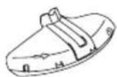
Cutting tool Protector
Nylon cutting head

Plastic blade

Installing the protector

WARNING: Never use the tool without the guard or with the guard improperly installed.
Failure to do so can cause serious personal injury.
NOTE: The type of the protector supplied as the standard accessory varies depending on the countries.
For cutter blade
Attach the protector to the clamp using bolts.
▶ Fig.18: 1. Clamp 2. Protector
For nylon cutting head / plastic blade

CAUTION: Take care not to injure yourself on the cutter for cutting the nylon cord.
Attach the protector to the clamp using bolts. After that, install the protector extension. Insert the protector extension to the protector and then snap the clips on. Make sure that the tabs on the protector extension fit into the slots on the protector.
▶ Fig.19: 1. Protector 2. Clip 3. Protector extension 4. Cutter 5. Slot 6. Tab
To remove the protector extension from the protector, unclasp the clips by inserting the hex wrench as illustrated.
▶ Fig.20: 1. Hex wrench 2. Clip
Installing the cutting tool

CAUTION: Always use the supplied wrenches remove or to install the cutting tool.

CAUTION: Be sure to remove the hex wrench inserted into the tool head after installing the setting tool.
NOTE: The type of the cutting tool(s) supplied as the standard accessory varies depending on the countries. The cutting tool is not included in some countries.
NOTE: Turn the tool upside down so that you can replace the cutting tool easily.
Cutter blade
⚠️ CAUTION: When handling a cutter blade, always wear gloves and put the blade cover on the blade.
⚠CAUTION: The cutter blade must be well polished, and free of cracks or breakage. If the cutter blade hits a stone during operation, stop the tool and check the cutter blade immediately.
⚠️CAUTION: Always use the cutter blade with the diameter described in the section for specifications.
- Put the blade cover on the cutter blade.
2-tooth blade
▶ Fig.21
3-tooth blade
▶ Fig.22
4-tooth blade
▶ Fig.23
- Insert the hex wrench through the hole in the gear case to lock the spindle. Rotate the spindle until the hex wrench is fully inserted.
▶ Fig.24: 1. Nut 2. Cup 3. Clamp washer 4. Cutter blade 5. Spindle 6. Receive washer 7. Hex wrench
3. Mount the cutter blade onto the receive washer so that the arrows on the cutter blade and protector are pointing in the same direction.
▶ Fig.25: 1. Arrow
4. Put the clamp washer and cup onto the cutter blade and then tighten the nut securely by the box wrench.
▶ Fig.26: 1. Box wrench 2. Hex wrench 3. Loosen 4. Tighten
NOTE: Tightening torque : 20 - 30 N•m
- Remove the hex wrench from the gear case.
To remove the cutter blade, follow the installation procedures in reverse.
Nylon cutting head
NOTICE: Be sure to use genuine Makita nylon cutting head.
There are two types of nylon cutting head; the bump & feed type and the manual feed type.
Bump & feed type
▶ Fig.27: 1. Nylon cutting head 2. Spindle 3. Hex wrench 4. Loosen 5. Tighten
- Insert the hex wrench through the hole in the gear case to lock the spindle. Rotate the spindle until the hex wrench is fully inserted.
- Place the nylon cutting head onto the spindle and tighten it securely by hand.
- Remove the hex wrench from the gear case.
To remove the nylon cutting head, follow the installation procedures in reverse.
Manual feed type
▶ Fig.28: 1. Nut 2. Nylon cutting head 3. Spindle 4. Hex wrench
- Insert the hex wrench through the hole in the gear case to lock the spindle. Rotate the spindle until the hex wrench is fully inserted.
- Place the nylon cutting head onto the spindle and tighten the nut securely by the box wrench.
▶ Fig.29: 1. Box wrench 2. Hex wrench 3. Loosen
-
Tighten
-
Remove the hex wrench from the gear case.
To remove the nylon cutting head, follow the installation procedures in reverse.
Plastic blade
NOTICE: Be sure to use genuine Makita plastic blade.
▶ Fig.30: 1. Plastic blade 2. Spindle 3. Hex wrench 4. Loosen 5. Tighten
- Insert the hex wrench through the hole in the gear case to lock the spindle. Rotate the spindle until the hex wrench is fully inserted.
- Place the plastic blade onto the spindle and tighten it securely by hand.
- Remove the hex wrench from the gear case.
To remove the plastic blade, follow the installation procedures in reverse.
OPERATION
Adjusting the working position
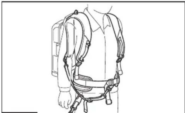
⚠️ CAUTION: Before performing this procedure, install the battery cartridge(s) to the portable power pack and finish the adjustments for the waist belt and shoulder harness. Refer to the instruction manual of the portable power pack for detail.
⚠️ CAUTION: To prevent unintentional start up, never turn on the portable power pack throughout this procedure. The battery cartridge(s) is to be installed only to obtain the usability with actual weight balance.
⚠️ CAUTION: When you use the tool in combination of the backpack-type power supply such as portable power pack, use the hanging band included in the tool package or the hanging band recommended by Makita.
If you put on the shoulder harness not recommended by Makita and the shoulder harness of the back-pack-type power supply at the same time, removing the tool or backpack-type power supply is difficult in case of an emergency, and it may cause an accident or injury. For the recommended hanging band, ask Makita Authorized Service Centers.
- Pull out the cord from the right side of the portable power pack. When pulling out the cord, be sure to set
the cord in the holders as shown in the figure.
▶ Fig.31: 1. Cord 2. Holder
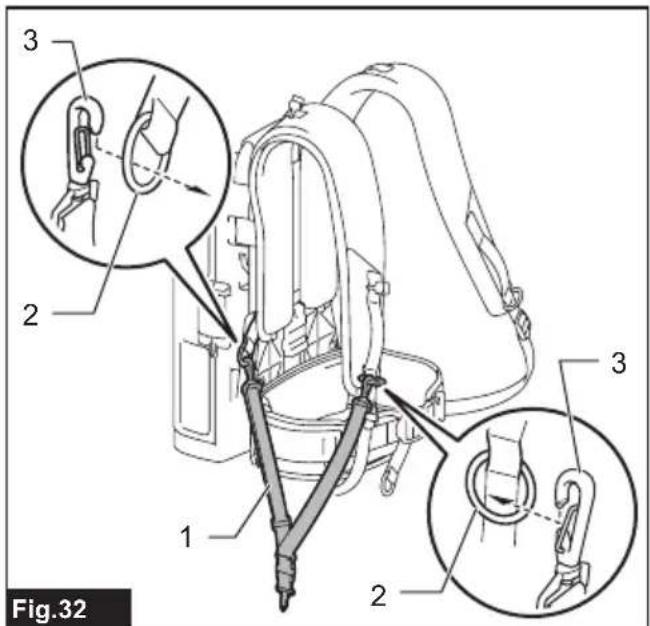
- Attach the hooks of the hanging band to the rings of the shoulder belts or waist harness as shown in the figure.
Attaching hanging band to the shoulder belt
▶ Fig.32: 1. Hanging band 2. Ring 3. Hook
Attaching hanging band to the shoulder belt and waist belt
▶ Fig.33: 1. Hanging band 2. Ring 3. Hook
- Wear the shoulder harness of the portable power pack and lock the buckle on the waist belt.
▶ Fig.34
Adjust the length of the hanging band as necessary.
▶ Fig.35
- Attach the tool to the shoulder harness using the hook on the hanging band. Be sure to hook on the hanger of the tool.
UR101C
▶ Fig.36: 1. Hook 2. Hanger
UR201C
▶ Fig.37: 1. Hook 2. Hanger
- Insert the plug of the tool into the socket of the portable power pack.
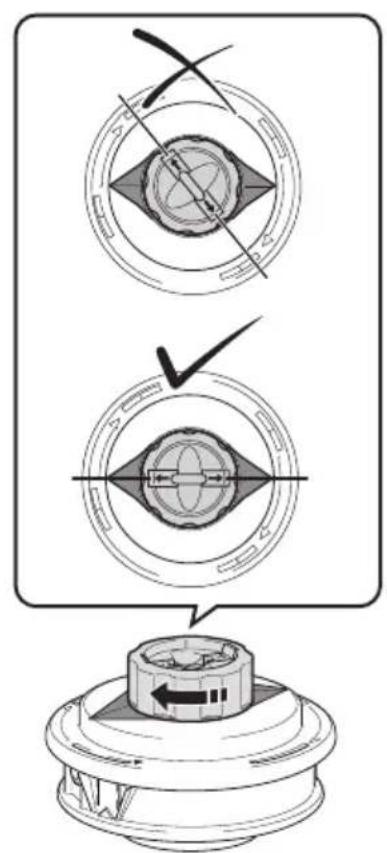
When inserting, align the triangle marking on both the plug and the socket.
UR101C
▶ Fig.38: 1. Plug 2. Socket 3. Triangle marking
UR201C
▶ Fig.39: 1. Plug 2. Socket 3. Triangle marking
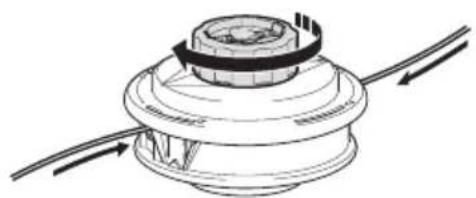
- Adjust the cord length using the holder as necessary.
▶ Fig.40: 1. Holder
The cord length is properly adjusted when you can;
— swing the tool without any hindrance by the cord;
— swing the tool without letting the cord flopping and;
— disconnect the plug from the socket without taking off the shoulder harness of the portable power pack.
⚠CAUTION: Allow the cord to have a appropriate play between the tool and portable power pack. If the play is too little, the tool movement may be hindered. If the play is too much, the cord may be caught by other object and result in accident.
Adjusting the hanger position
For UR101C only
For more comfortable handling of the tool, you can change the hanger position.
- Loosen the screw on the hanger and slide it to a comfortable working position.
▶ Fig.41: 1. Hanger 2. Screw 3. Cord
NOTICE: When adjusting the hanger position, also adjust the cord position.
- Adjust the hanger position as shown in the figure and then tighten the screw.
▶ Fig.42
| 1 The hanger position from the ground |
| 2 The cutting tool position from the ground |
| 3 The horizontal distance between the hanger and the unguarded part of the cutting tool |
Starting the operation
CAUTION: Before operation, finish adjusting the working position by following the instructions in the section for the working position.
CAUTION: Before operation, make sure that the buckles on the waist belt is locked and the tool is securely attached to the hook of the hanging band.
CAUTION: Always press the main power button to turn on the tool immediately before cutting grass. Failure to do so may cause personal injury due to unintentional start up.
- Install the battery cartridge(s) to the portable power pack.
▶ Fig.43: 1. Portable power pack 2. Battery cartridge
NOTE: Refer to the instruction manual of your portable power pack for how to install the battery cartridges.
- Press the power button on the portable power pack. The main power lamp will light up.
▶ Fig.44: 1. Main power lamp 2. Power button
- Wear the shoulder harness of the portable power pack and lock the buckle on the waist belt.
▶ Fig.45
- Attach the tool to the shoulder harness using the hook on the hanging band. Be sure to hook on the hanger of the tool.
UR101C
▶ Fig.46: 1. Hook 2. Hanger
UR201C
▶ Fig.47: 1. Hook 2. Hanger
- Insert the plug of the tool into the socket of the portable power pack.
When inserting, align the triangle marking on both the plug and the socket.
UR101C
▶ Fig.48: 1. Plug 2. Socket 3. Triangle marking
UR201C
▶ Fig.49: 1. Plug 2. Socket 3. Triangle marking
- Tap the main power button to turn on the tool.
The tool is ready to operate. The tool will run when you pull the switch trigger.
▶ Fig.50: 1. Main power button
⚠️CAUTION: When suspending the operation, always turn off the tool and remove the plug from the socket. Failure to do so may cause personal injury due to unintentional start up.
When quitting the operation, press and hold the main power button until the speed indicator goes off and then perform the above procedure in reverse.
Correct handling of the tool
WARNING: Always position the tool on your right-hand side. Correct positioning of the tool allows for maximum control and will reduce the risk of serious personal injury caused by kickback.
WARNING: Be extremely careful to maintain control of the tool at all times. Do not allow the tool to be deflected toward you or anyone in the work vicinity. Failure to keep control of the tool could result in serious injury to the bystander and the operator.
WARNING: To avoid accident, leave more than 15m (50 ft) distance between operators when two or more operators work in one area. Also, arrange a person to observe the distance between operators. If someone or an animal enters the working area, immediately stop the operation.
⚠️CAUTION: If the cutting tool accidentally impacts a rock or hard object during operation, stop the tool and inspect for any damage. If the cutting tool is damaged, replace it immediately. Use of a damaged cutting tool may result in serious personal injury.
⚠️CAUTION: Remove the blade cover from the cutter blade when cutting the grass.
Correct positioning and handling allow optimum control and reduce the risk of injury caused by kickback.
UR101C
▶ Fig.51
UR201C
▶ Fig.52
When using a nylon cutting head (bump & feed type)
The nylon cutting head is a dual string trimmer head provided with a bump & feed mechanism.
To feed out the nylon cord, tap the cutting head against the ground while rotating.
▶ Fig.53: 1. Most effective cutting area
NOTICE: The bump feed will not operate properly if the nylon cutting head is not rotating.
NOTE: If the nylon cord does not feed out while tapping the head, rewind/replace the nylon cord by following the procedures in the section for the maintenance.
Emergency detachment
⚠️ CAUTION: In case of emergency detachment, pay extra attention to the position of the rotating cutting tool.
In case of emergency, detach the tool in either way described below:
Unlock the buckle on the waist belt and take off the shoulder harness of the portable power pack which is connected to the tool.
▶ Fig.54: 1. Buckle
Unlock the buckle on the hanging band and release the tool. The cord will be disconnected by the weight of the tool.
▶ Fig.55: 1. Buckle
MAINTENANCE
WARNING: Always be sure that the tool is switched off and the portable power pack is disconnected from the tool before attempting to perform inspection or maintenance on the tool. Failure to switch off and disconnect the portable power pack may result in serious personal injury from accidental start-up.
NOTICE: Never use gasoline, benzine, thinner, alcohol or the like. Discoloration, deformation or cracks may result.
To maintain product SAFETY and RELIABILITY, repairs, any other maintenance or adjustment should be performed by Makita Authorized or Factory Service Centers, always using Makita replacement parts.
Cleaning the tool
Clean the tool by wiping off dust, dirt, or cut off grass with a dry cloth or one dipped in soapy water and wrung out. To avoid overheating of the tool, be sure to remove the cut off grass or debris adhered to the vent of the tool.
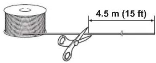
Replacing the nylon cord
WARNING: Use only the nylon cord with diameter specified in this instruction manual. Never use heavier line, metal wire, rope or the like. Failure to do so may cause damage to the tool and result in serious personal injury.
WARNING: Always remove the nylon cutting head from the tool when replacing the nylon cord.
WARNING: Make sure that the cover of the nylon cutting head is secured to the housing properly as described in this instruction manual. Failure to properly secure the cover may cause the nylon cutting head to fly apart resulting in serious personal injury.
Replace the nylon cord if it is not fed any more. The
method of replacing the nylon cord varies depending on the type of the nylon cutting head.
95-M10L
▶ Fig.56
96-M10L
▶ Fig.57
98-M10L
▶ Fig.58
B&F ECO 4L
▶ Fig.59
UN-74L, UN-72L
▶ Fig.60
Manual feed type
When the nylon cord gets short, pull it out from the eyelet and feed it from the another eyelet.
▶ Fig.61
Replacing the plastic blade
Replace the plastic blade if it is worn out or broken.
▶ Fig.62
When installing the plastic blade, align the direction of the arrow on the blade with that of the protector.
▶ Fig.63: 1. Arrow on the protector 2. Arrow on the blade
TROUBLESHOOTING
Before asking for repairs, conduct your own inspection first. If you find a problem that is not explained in the manual, do not attempt to dismantle the tool. Instead, ask Makita Authorized Service Centers, always using Makita replacement parts for repairs.
| State of abnormality Probable cause | (malfunction) Remedy | |
| Motor does not run. Battery cartridge is | not installed. Install the battery cartridge. | |
| Battery problem (under voltage) Recharge | the battery cartridge. If recharging is not effective, replace battery cartridge. | |
| The drive system does not work correctly. | Ask your local authorized service center for repair. | |
| Motor stops running after a little use. | Battery's charge level is low. | Recharge the battery cartridge. If recharging is not effective, replace battery cartridge. |
| Overheating. Stop using of tool to allow it | to cool down. | |
| The tool does not reach maximum RPM. | Battery cartridge is installed improperly. | Install the battery cartridge as described in this manual. |
| Battery power is dropping. Recharge the | battery cartridge. If recharging is not effective, replace battery cartridge. | |
| The drive system does not work correctly. | Ask your local authorized service center for repair. | |
| Cutting tool does not rotate: ⇒ stop the machine immediately! | Foreign object such as a branch is jammed between the guard and the cutting tool. | Remove the foreign object. |
| Cutting tool is loosely attached. Tighten the | cutting tool securely. | |
| The drive system does not work correctly. | Ask your local authorized service center for repair. | |
| Abnormal vibration: ⇒ stop the machine immediately! | Broken, bent or worn cutting tool Replace | the cutting tool. |
| Cutting tool is loosely attached. Tighten the | cutting tool securely. | |
| The drive system does not work correctly. | Ask your local authorized service center for repair. | |
| Cutting tool and motor cannot stop: ⇒ Disconnect the portable power pack from the tool immediately! | Electric or electronic malfunction. Disconnect the portable power pack from the tool and ask your local authorized service center for repair. | |
OPTIONAL ACCESSORIES
WARNING: Only use the recommended accessories or attachments indicated in this manual. The use of any other accessory or attachment may result in serious personal injury.
⚠️CAUTION: These accessories or attachments are recommended for use with your Makita tool specified in this manual. The use of any other accessories or attachments might present a risk of injury to persons. Only use accessory or attachment for its stated purpose.
If you need any assistance for more details regarding these accessories, ask your local Makita Service Center.
- Cutter blade
- Nylon cutting head
- Nylon cord (cutting line)
- Plastic blade
- Protector
- Makita genuine battery and charger
NOTE: Some items in the list may be included in the tool package as standard accessories. They may differ from country to country.
SPÉCIFICATIONS
natural_image
Three black geometric shapes on white background: elongated oval, triangular shape, and cross (no text or symbols)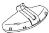
▶ Fig.40: 1. Support
▶ Abb.20: 1. Inbusschlüssel 2. Klammer
▶ Abb.54: 1. Schnalle
▶ Abb.55: 1. Schnalle
WARTUNG
⚠ WAARSCHUWING: Draag gehoorbescherming.
VEILIGHEIDSWAAR- SCHUWINGEN
▶ Fig.9: 1. ADT-lampje 2. Omkeerknop
OPTIONELE ACCESSOIRES
▶ Fig.15: 1. Llave hexagonal
▶ Fig.17: 1. Llave hexagonal
▶ Fig.20: 1. Llave hexagonal 2. Cierre
▶ Fig.40: 1. Abrazadera
▶ Fig.20: 1. Chave hexagonal 2. Clipe