
HC30PHTX1N - Range hood Fisher & Paykel - Free user manual and instructions
Find the device manual for free HC30PHTX1N Fisher & Paykel in PDF.
| Product type | Wall-mounted range hood |
| Brand | Fisher & Paykel |
| Model | HC30PHTX1N |
| Dimensions (W x H x D) | 755 x 655-1094 x 500 mm |
| Weight | 35 lb (16 kg) |
| Power supply | 120 V, 60 Hz, grounding required |
| Duct diameter | 6 in (152 mm) – rigid or semi-rigid |
| Control | Touch panel with speed display |
| Fan speeds | 4 levels (1 to 4) + maximum speed mode |
| Timer | Yes, automatic shut-off after 5 minutes (gradual ramp down) |
| Lighting | Halogen bulb (ref. 791961) |
| Filters | Washable aluminum filters (ref. 792558); charcoal filters for recirculation (ref. 791772) |
| Venting modes | Ducted (exhaust) or recirculation (requires conversion kit ref. 792560) |
| Maintenance | Regular cleaning with mild detergent; aluminum filters dishwasher safe |
| Installation | Solid wall, height between 660 and 762 mm above cooking surface |
| Safety | Disconnect power before maintenance; use metal ductwork only |
| Warranty | Manufacturer warranty (see separate manual) |
| Replacement parts | Bulb (791961), aluminum filter (792558), charcoal filter (791772), recirculation deflector (792560) |
| Repairability | User replaceable bulbs and filters; repair by qualified professional |
Frequently Asked Questions - HC30PHTX1N Fisher & Paykel
User questions about HC30PHTX1N Fisher & Paykel
0 question about this device. Answer the ones you know or ask your own.
Ask a new question about this device
Download the instructions for your Range hood in PDF format for free! Find your manual HC30PHTX1N - Fisher & Paykel and take your electronic device back in hand. On this page are published all the documents necessary for the use of your device. HC30PHTX1N by Fisher & Paykel.
USER MANUAL HC30PHTX1N Fisher & Paykel
INSTALLATION GUIDE/USERGUIDE
GUIDE D'INSTALLATION/GUIDE D'UTILISATION
US CA
English Page 1-22
Français
Introduction
Safety and warnings 4
Installation instructions 6
Operating instructions 18
Cleaning and maintenance 19
Parts and accessories 21
Service and Warranty 22
3
IMPORTANT!
SAVE THESE INSTRUCTIONS
The models shown in this user guide may not be available in all markets and are subject to change at any time. For current details about model and specification availability in your country, go to our website fisherpaykel.com or contact your local Fisher & Paykel dealer.
Registration
Register your product with us so we can provide you with the best service possible.
To register your product visit our website: fisherpaykel.com
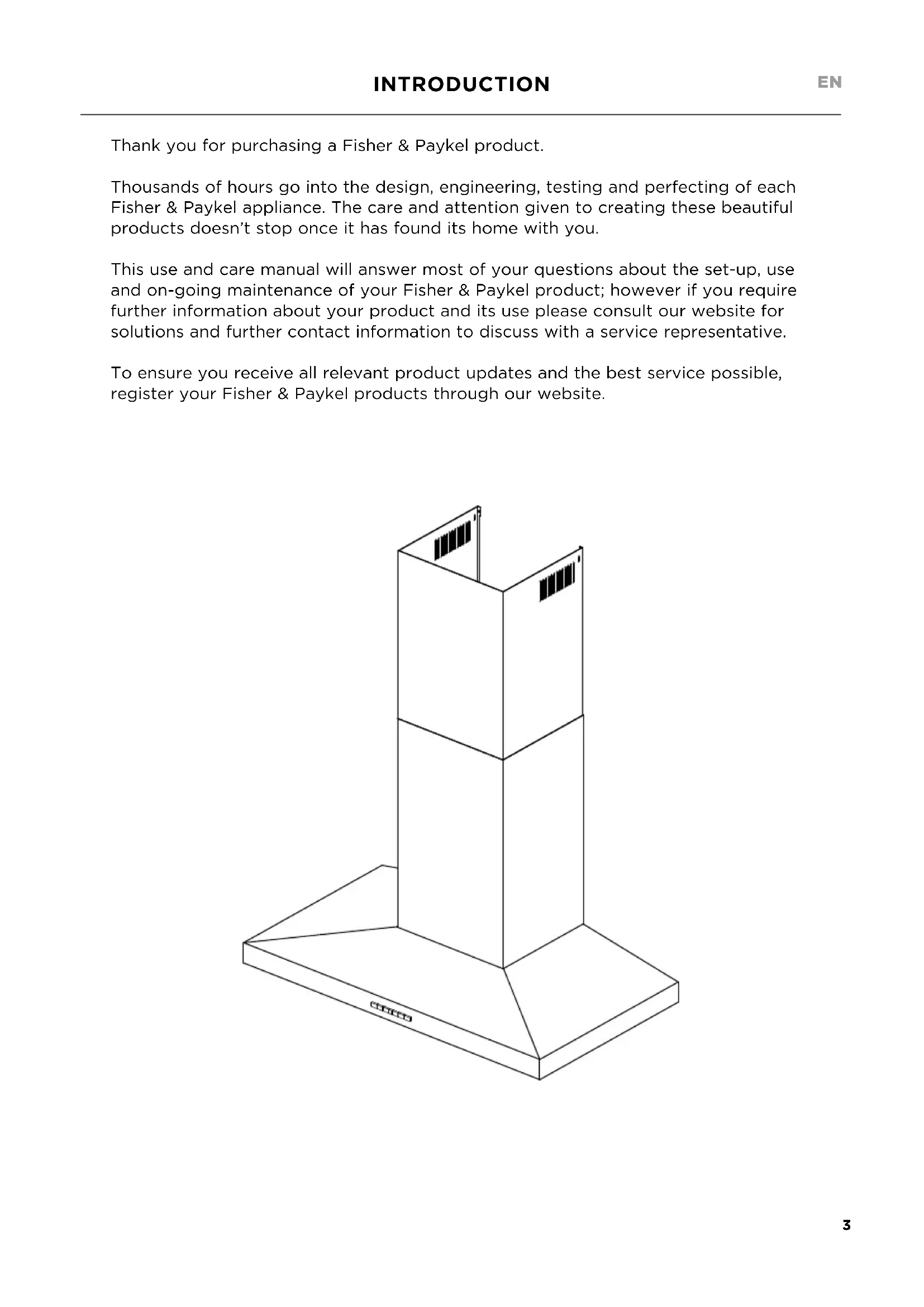
Thank you for purchasing a Fisher & Paykel product.
Thousands of hours go into the design, engineering, testing and perfecting of each Fisher & Paykel appliance. The care and attention given to creating these beautiful products doesn't stop once it has found its home with you.
This use and care manual will answer most of your questions about the set-up, use and on-going maintenance of your Fisher & Paykel product; however if you require further information about your product and its use please consult our website for solutions and further contact information to discuss with a service representative.
To ensure you receive all relevant product updates and the best service possible, register your Fisher & Paykel products through our website.
WARNING!
33 lb (15 kg) (HC24)
35 lb (16 kg) (HC30)
37 lb (17 kg) (HC36)
Weight Hazard
The ventilation hood is heavy. Please ensure adequate care is taken when installing the ventilation hood to prevent personal injury.
The ventilation hood must be installed onto a solid wall, stud, beam or truss.
Weight of the products are 33 lb (15 kg) HC24 / 35 lb (16 kg) HC30 / 37 lb (17 kg) HC36.
WARNING!

Electric Shock Hazard
Always disconnect the appliance from the mains power supply before carrying out any maintenance or repairs.
Installation work and electrical wiring must be done by qualified person(s) in accordance with all applicable codes and standards, including fire-rated construction.
Failure to do so can result in death, electric shock, fire or injury to persons.
IMPORTANT SAFETY INSTRUCTIONS
READ THE ENTIRE SET OF INSTRUCTIONS BEFORE INSTALLING OR USING THIS APPLIANCE. Manuals can also be found on our website fisherpaykel.com.
-
CAUTION: For general ventilating use only. Do not use to exhaust hazardous or explosive materials and vapors.
WARNING! To reduce the risk of fire, electric shock, or injury to persons, observe the following: -
Use this unit only in the manner intended by the manufacturer. If you have questions, contact the manufacturer. For residential use only.
- Before servicing or cleaning unit, switch power off at service panel and lock the service disconnecting means to prevent power from being switched on accidentally. When the service disconnecting means cannot be locked, securely fasten a prominent warning device, such as a tag, to the service panel.
- Installation work and electrical wiring must be done by qualified person(s) in accordance with all applicable codes and standards, including fire-rated construction.
-
Sufficient air is needed for proper combustion and exhausting of gases through the flue (chimney) of fuel burning equipment to prevent back drafting. Follow the heating equipment manufacturer's guideline and safety standards such as those published by the National Fire Protection Association (NFPA), and the American Society for Heating, Refrigeration and Air Conditioning Engineers (ASHRAE), and the local code authorities.
-
When cutting or drilling into wall or ceiling, do not damage electrical wiring and other hidden utilities.
- Ducted fans must always be vented to the outdoors.
-
This unit must be grounded.
-
CAUTION: To reduce risk of fire and to properly exhaust air, be sure to duct air outside - Do not vent exhaust air into spaces within walls or ceilings or into attics, crawl spaces, or garages.
WARNING: To reduce the risk of fire, use only metal ductwork. -
WARNING: To reduce the risk of fire or electric shock, do not use this fan with any solid-state speed control device.
WARNING: To reduce the risk of a range top grease fire: -
Never leave surface units unattended at high settings. Boilovers cause smoking and greasy spillovers that may ignite. Heat oils slowly on low or medium settings.
- Always turn hood ON when cooking at high heat or when flambéing food (ie Crepes Suzette, Cherries Jubilee, Peppercorn Beef Flambé)
- Clean ventilating fans frequently. Grease should not be allowed to accumulate on fan or filter.
-
Use proper pan size. Always use cookware appropriate for the size of the surface element.
-
WARNING: To reduce the risk of injury to persons in the event of a range top grease fire, observe the following*:
-
SMOTHER FLAMES with a close-fitting lid, cookie sheet, or metal tray, then turn off the burner. BE CAREFUL TO PREVENT BURNS. If the flames do not go out immediately, EVACUATE AND CALL THE FIRE DEPARTMENT.
- NEVER PICK UP A FLAMING PAN - You may be burned.
-
DO NOT USE WATER, including wet dishcloths or towels - a violent steam explosion will result.
-
Use an extinguisher ONLY if:
-
You know you have a Class ABC extinguisher, and you already know how to operate it.
- The fire is small and contained in the area where it started.
- The fire department is being called.
- You can fight the fire with your back to an exit.
WARNING: Unplug or disconnect the appliance from the power supply before servicing or cleaning.
- CAUTION: To reduce the risk of fire and electric shock when product is used in recirculation mode, use only conversion kit model 792560 Recirculation Diverter and 791772 Recirculation Carbon Filter x2.
READ AND SAVE THESE INSTRUCTIONS
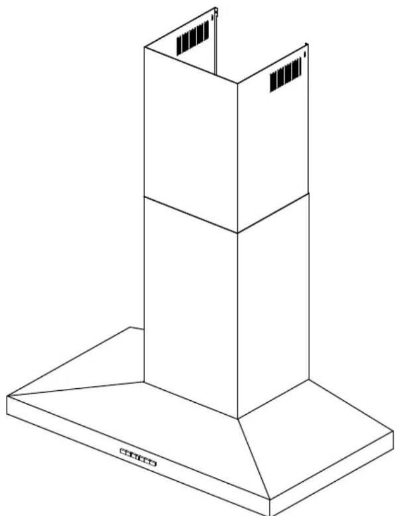
Contents of packaging

Ventilation hood (1)
Installation instructions User guide manual (1)
Chimney (1)
Upper chimney (1)

Upper chimney bracket (1)
Chimney bracket (1)
Power connection box (1)
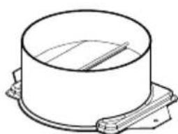
6" (152 mm) diameter Ducting adapter with back draft damper (1)
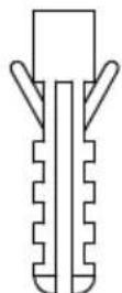
1316 (30 mm) Expansion plug (10)
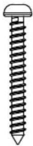
1^3 / 16 (30 mm)
Self tapping screw
(10)
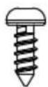
13 / 32 (10 mm)
Self tapping screw
(4)
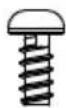
13/32" (10 mm)
Screw
(2)
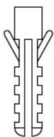
1^23 / 32 (44 mm)
Drywall expansion plug
(8)
Product dimensions
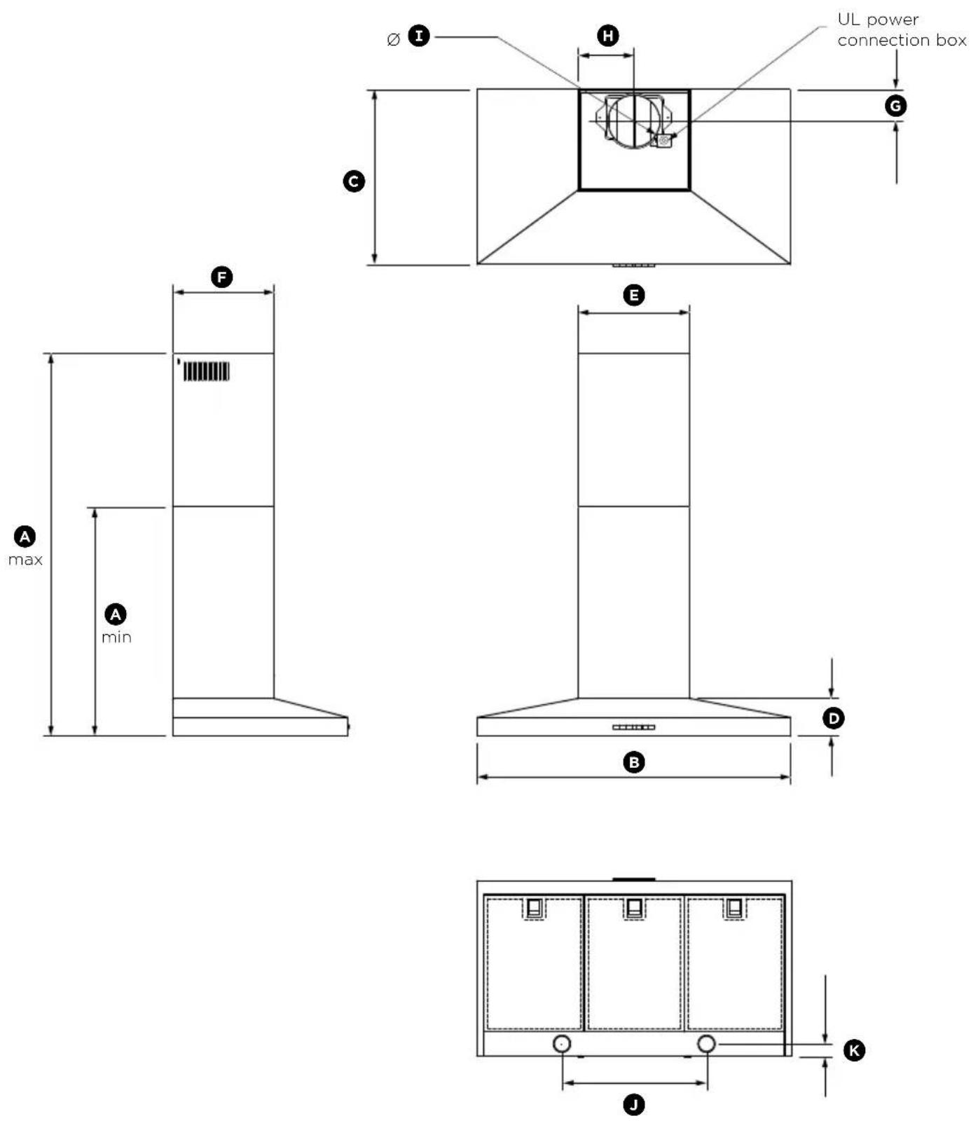
Please read the entire instructions before installing the ventilation hood.
HC24PHTX1 HC30PHTX1 HC36PHTX1
| PRODUCT DIMENSIONS | inches (mm) | inches (mm) | inches (mm) | |
| A | Min overall height of product 2525/32" (655) 2525/32" (655) | (655) | (655) | (655) |
| A | Max overall height of product 431/6" (1094) 431/6" (1094) | (1094) | (1094) | (1094) |
| B | Overall width of product 2317/32" (598) 2923/32" (755) | 3511/32" (898) | ||
| C | Overall depth of product 1911/6" (500) 1911/6" (500) | 1911/6" (500) | ||
| D | Height of product 41/2" (114) 41/2" (114) | 41/2" (114) | ||
| E | Width of chimney | 1219/32" (320) | 1219/32" (320) | 1219/32" (320) |
| F | Depth of chimney | 1113/32" (290) | 1113/32" (290) | 1113/32" (290) |
| G | Distance from center of ducting outlet to back of product | 33/4" (95) | 33/4" (95) | 33/4" (95) |
| H | Distance from center of ducting outlet to side of chimney | 65/6" (160) | 65/6" (160) | 65/6" (160) |
| I | Diameter of ducting outlet | 529/32" (150) | 529/32" (150) | 529/32" (150) |
| J | Distance between center of lights | 161/4" (413) | 161/4" (413) | 161/4" (413) |
| K | Distance between center of lights and back of product | 121/32" (42) | 121/32" (42) | 121/32" (42) |
IMPORTANT!
Actual product dimensions may vary by ± 32 (2 mm).

Height of ventilation hood
| INSTALLATION DIMENSIONS | inches (mm) |
| L Installation heightDuctedRecirculation | min. 262532”-max. 4316" (min. 680-max. 1094)min. 2918”-max. 4316" (min. 740-max. 1094) |
| M Height top of cooktopto base of product | min. 26”-max. 30" (min. 660-max. 762) |
Ventilation hood installation height above the cooktop is the user's preference. Lower installation heights will improve the efficiency of capturing cooking odors, grease, and smoke. This ventilation hood must be installed between the minimum and maximum dimensions indicated in the table above.
WARNING!
To reduce the risk of fire, use only metal ductwork. Do not use flexible plastic ducting.
CAUTION!
To reduce risk of fire and to properly exhaust air, be sure to duct air outside - do not vent exhaust air into spaces within walls or ceilings or intoAttics, crawl spaces, or garages.
Venting options
Attention should be given to ensure that any applicable regulations concerning the discharge of exhaust air are fulfilled.
The ventilation hood can be installed to operate with the exhaust air ducted externally from the kitchen, or installed to operate with the exhaust air recirculating within the kitchen.
Ducted
For ducted installation it is recommended that 6'' (152 mm) diameter, rigid or semi-rigid ducting is used. This will require a 6516 (160 mm) (min) round hole in the ceiling or wall. Care should be taken to position the hole correctly.
For optimal efficiency use the shortest and straightest duct route possible and use rigid or semi-rigid ducting for reduced noise and increased airflow. Flexible metal ducting should only be used as a last resort (ie in difficult installations) and if used ensure that it is straight and smooth and extended as much as possible.
Recirculating
To enable the product to operate with the air recirculating, purchase a recirculation diverter and carbon filters (refer to the 'Parts and accessories' section). This recirculation diverter is required to channel the air out the side vents at the top of the chimney and the carbon filters are required to remove odors.
Note: a ducting hole is not required in the wall or ceiling if the ventilation hood is installed to operate with exhaust air recirculating.
WARNING!
- This product is heavy and requires two persons for installation.
- Installation work and electrical wiring must be done by qualified person(s) in accordance with all applicable codes and standards.
IMPORTANT!
Wear gloves to protect against sharp edges.
The manufacturer is not liable for any damage caused by not following these instructions.
Installation
① Preparing for installation:
Before installing your ventilation hood:
- Please read the instructions carefully.
- Unpack the ventilation hood.
- Ensure the voltage (V) and the frequency (Hz) indicated on the serial plate match the voltage and frequency of the installation site.
- Check that the area behind the installation surface to be drilled is clear of any electrical cables or pipes etc
- The ventilation hood surfaces can be damaged during installation if grazed or knocked by tools. Please take care to protect the surfaces during installation.
- Protect the cooktop surface with cardboard, or the like, to prevent damage occurring whilst the ventilation hood is being installed above.
- Temporarily mark the height of the bottom of the ventilation hood and the center of the cooktop on the wall according to the information given in the 'Installation instructions - Height of ventilation hood' section.
- The wall used for mounting the ventilation hood should have sufficient strength and a flat surface.
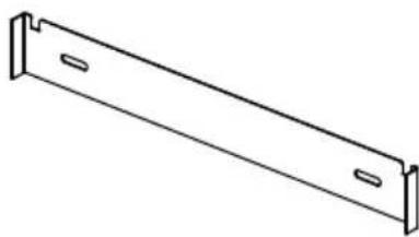
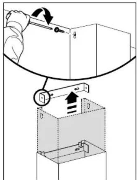
② Attach chimney brackets and ventilation hood mounting screws to the wall
- Attach the chimney bracket and upper chimney bracket (if using the upper chimney) in the locations shown in Fig.2 (refer to page 13) and Fig.3 (refer to page 14). Use the 1^3/16 (30 mm) screws (and expansion plugs if attaching to masonry).
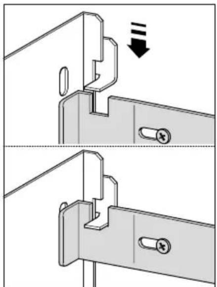
- Attach the upper ventilation hood mounting screws in the locations shown in Fig.2 (refer to page 13) and Fig.3 (refer to page 14). Using the 1^3/16 (30 mm) screws (and expansion plugs if attaching to masonry). Ensure that there is a 3/32 (2 mm) gap between the screw head and the wall (Fig.1).
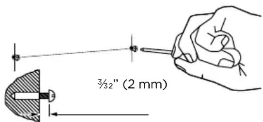
Fig.1
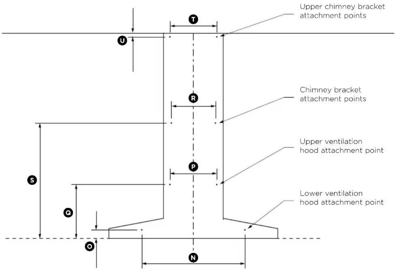
Fig.2
| PRODUCT DIMENSIONS | inches (mm) |
| Lower ventilation hood attachment point width 20" (508) | |
| Lower ventilation hood attachment point height 113/16" (46) | |
| Upper ventilation hood attachment point width 97/8" (250) | |
| Upper ventilation hood attachment point height 113/8" (288) | |
| Chimney bracket attachment point width 91/4" (235) | |
| Chimney bracket attachment point height 241/4" (616) | |
| Upper chimney bracket attachment point width 97/8" (250) | |
| Upper chimney bracket attachment point height 1" (25) |
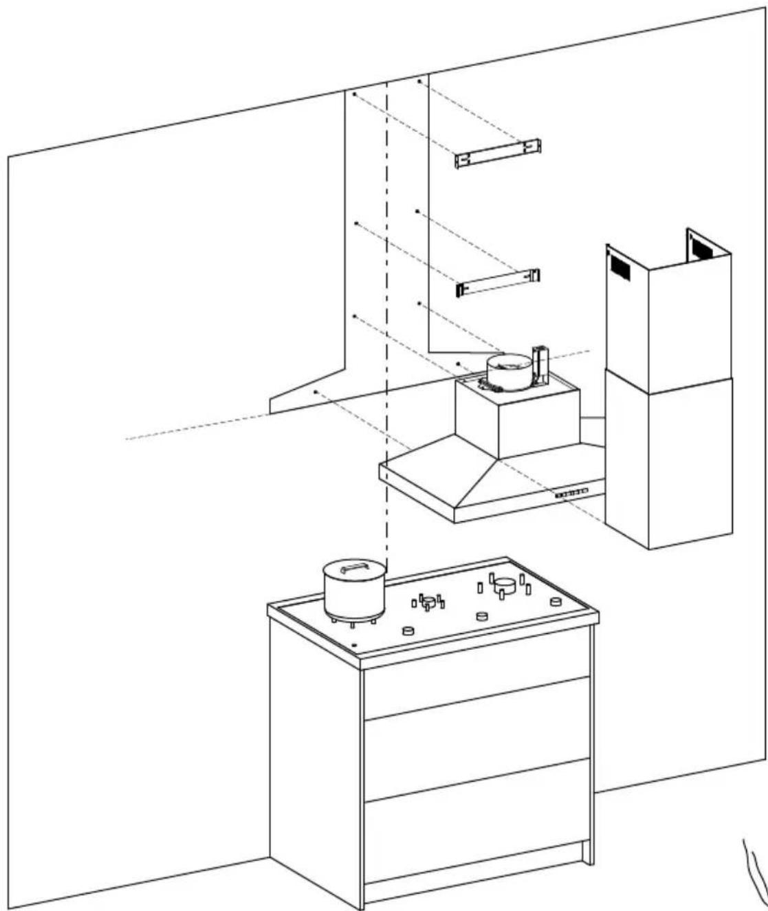
Fig.3
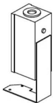
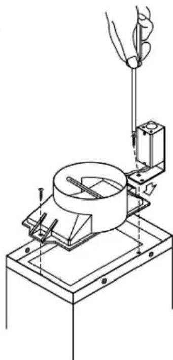
③ Attach ducting adapter and power connection box to the ventilation hood
- Place the ducting adapter onto the ventilation hood and screw it in place using 13 (10 mm) screws.
- Place the power connection box onto the ventilation hood and screw it in place using 13/2 (10 mm) screws.
- Follow wiring instructions described in the 'Electrical connection' section page 16.
④ Wall mounting
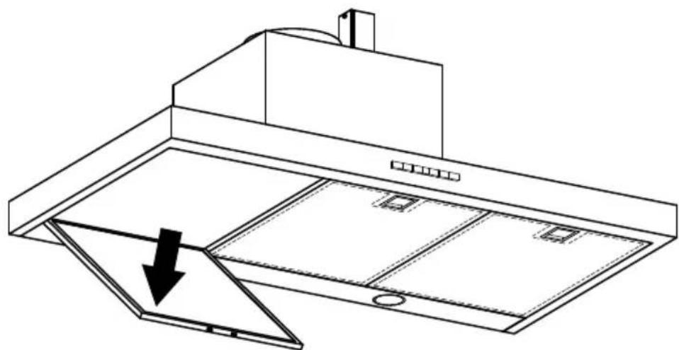
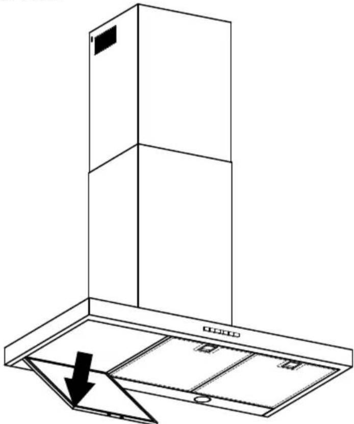
- Remove the filters - pull the relative catch and tilt the filter downwards until it disengages from the supports.
- Hang the ventilation hood off the upper ventilation hood mounting screws with 32 (2 mm) gap. Hang off the keyhole attachment points on the back of the ventilation hood then tighten the screws.
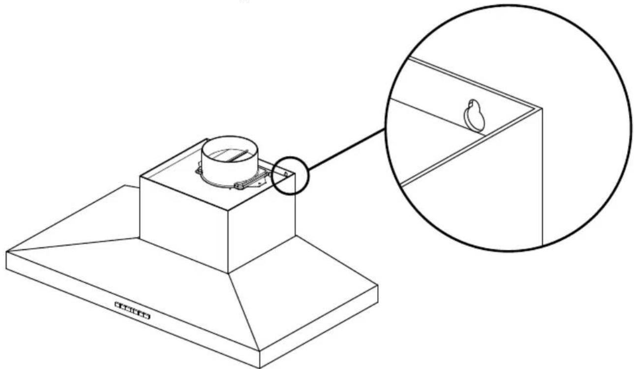
- Attach the lower ventilation hood mounting screws to fix the ventilation hood to the wall.
- Refit the filters.
WARNING!
Electrical wiring must be done by qualified person(s) in accordance with all applicable codes and standards and the unit must be grounded.
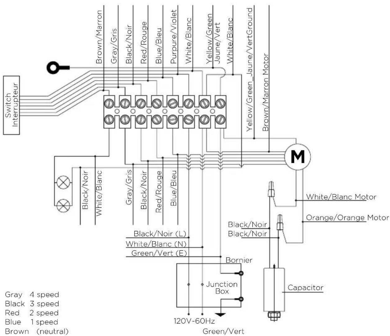
⑤ Electrical connection
- Run three wires, two for the power supply and one for the ground wire, from the power connection box on the ventilation hood to a power connection point near the installation.
- Open the power connection box on the ventilation hood and secure the power conductor with a strain relief (not included).
- Connect the power conductors to the conductors for the ventilation hood, black to black and white to white.
- Connect the grounding wire (green or bare) to the ground conductor (green) of the ventilation hood power connection box.
- Secure all the connections with wire nuts.
- Replace the power connection box cover.
⑥ Attach the ducting
- Attach ducting to the ducting adapter using aluminum duct tape and vent outside.
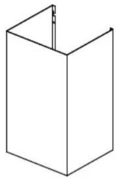
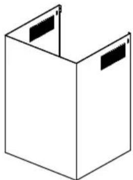
⑦ Attach chimney
- Bend the tabs on the chimney (A).
- Place chimney around the ventilation hood chassis and hang off the chimney bracket (B).
- Extend the upper chimney and attach to the upper chimney bracket with 1312 (10 mm) screws (C).

ABC
Remove packaging
- Remove all packaging and protective wrappings.
Touch control panel
| ① | - | 己 | + | ⊗ | ① |
CONTROL PANEL FEATURES
| Light Turn the lights on or off. | |
| ① | Power ON/OFF Turn the ventilation hood on or off. The fan automatically turns on to operate at level 1. |
| - | Reduce fan speed Adjust the fan speed levels from 1-4 with 1 being the lowest. |
| 2 | Fan speed indicator The fan speed level icon illuminates red with the current fan speed. |
| + | Increase fan speed Adjust the fan speed levels from 1-4 with 4 being the highest. |
| ⊗ | Max Turn the fan on directly onto maximum fan speed. |
| L | Timer Turn the timer on. The fan speed light blinks and the fan will operate for 5 minutes at the current speed and each decreasing speed before turning off (the fan will stop and the light will go out). To cancel the timer press the timer button once. |
Note: for optimal performance it is recommended that the ventilation hood is turned on before cooking is started.
IMPORTANT!
The ventilation hood may stop working during an electrostatic discharge (eg lightning). Switch off the electricity supply to the ventilation hood and reconnect after one minute.
WARNING!
Unplug or disconnect the appliance from the power supply before servicing or cleaning.
IMPORTANT!
- Never use abrasive or oil based cleaners.
- Wear gloves to protect against sharp edges.
Maintenance
The ventilation hood should be cleaned regularly using a mild, liquid detergent and a clean soft cloth to avoid a build-up of grease occurring. Avoid the use of corrosive chemicals, abrasive cleaning products, hard brushes and steel wool pads. Grease deposits are corrosive which can cause damage to your ventilation hood.
Note: in areas of high humidity or coastal environments, cleaning should be carried out more frequently.
Aluminum filters
- Depending on use, and at least once a month, the aluminum filters should be removed and cleaned with hot soapy water or in a dishwasher.
- If washed in a dishwasher, the filter should be placed in an upright position to prevent food from falling on them.
After rinsing and drying, refit the filters.
Note: some discoloration of the frames may occur.
Removing the aluminum filters:
① Pull the relative catch, tilting the filter downwards until it disengages from the supports.
② Reverse these instructions when refitting the filters.
WARNING!
When replacing the bulb, let the bulb cool, and assure that power to the ventilation hood has been turned off. Use new bulbs according to that indicated on the ventilation hood nameplate.
Carbon filters - for use in recirculation mode
Active carbon filters are disposable items designed to remove grease and odors from cooking vapors before the air is channeled back into the kitchen. The active carbon filters must be replaced periodically to work properly, at least once every three months, depending on the frequency with which the ventilation hood is used.
Note: fully saturated carbon filters can become a barrier to air movement therefore limiting ventilation hood performance. In the event of fire, grease laden filters could be flammable and therefore regular replacement is recommended.
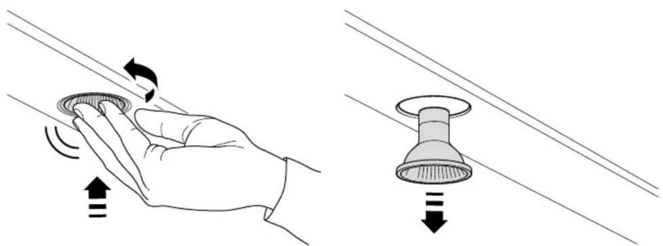
Replacing the light bulb
Note: replacement bulbs are not covered by warranty.
① Remove the aluminum filters
② Lightly push the light bulb up and rotate anti-clockwise to remove
③ Replace light bulb with a light bulb no more powerful than that specified.
④ Refit the aluminum filters
| ITEM REFERENCE NUMBER |
| Halogen bulb 791961 |
| Aluminum filter 792558 |
| Recirculation carbon filter x2 791772 |
| Recirculation diverter 792560 |
| Semi rigid ducting kit 150 mm (eaves) PD-RHK150E |
| Semi rigid ducting kit 150 mm (wall) PD-RHK150W |
For details of your manufacturer's warranty and contacts for servicing, please refer to your separate service and warranty book provided with your range hood.
Complete and keep for safe reference:
Model
Serial No.
Purchase Date
Purchaser
Dealer
City
State
Zip
Country
Introduction
27
Fisher & Paykel Appliances 2018. All rights reserved.
The product specifications in this booklet apply to the specific products and models described at the date of issue. Under our policy of continuous product improvement, these specifications may change at any time. You should therefore check with your Dealer to ensure this booklet correctly describes the product currently available.

- English Page 1-22
- Français
- IMPORTANT!
- SAVE THESE INSTRUCTIONS
- Registration
- WARNING!
- IMPORTANT SAFETY INSTRUCTIONS
- READ AND SAVE THESE INSTRUCTIONS
- Contents of packaging
- Product dimensions
- CAUTION!
- Venting options
- Ducted
- Recirculating
- Installation
- ③ Attach ducting adapter and power connection box to the ventilation hood
- ⑤ Electrical connection
- ⑥ Attach the ducting
- ⑦ Attach chimney
- Remove packaging
- Maintenance
- Aluminum filters
- Removing the aluminum filters:
- Carbon filters - for use in recirculation mode
- Replacing the light bulb
Brand : Fisher & Paykel
Model : HC30PHTX1N
Category : Range hood