FQHI 1200 X - Basket Fulgor Milano - Free user manual and instructions
Find the device manual for free FQHI 1200 X Fulgor Milano in PDF.
User questions about FQHI 1200 X Fulgor Milano
0 question about this device. Answer the ones you know or ask your own.
Ask a new question about this device
Download the instructions for your Basket in PDF format for free! Find your manual FQHI 1200 X - Fulgor Milano and take your electronic device back in hand. On this page are published all the documents necessary for the use of your device. FQHI 1200 X by Fulgor Milano.
USER MANUAL FQHI 1200 X Fulgor Milano
natural_image
Symbol of a trash bin crossed with no text or labelscod. 9.012.68.0.3'ed.
EN This product complies with EU Directive 2002/96/EC.
The crossed bin symbol on the appliance indicates that the product, at the end of its life, must be disposed of separately from domestic waste, either by taking it to a separate waste disposal site for electric and electronic appliances or by returning it to your dealer when you buy another similar appliance. The user is responsible for taking the appliance to a special waste disposal site at the end of its life. If the disused appliance is collected correctly as separate waste, it can be recycled, treated and disposed of ecologically; this avoids a negative impact on both the environment and health, and contributes towards the recycling of the product's materials. For further information regarding the waste disposal services available, contact your local waste disposal agency or the shop where you bought the appliance.
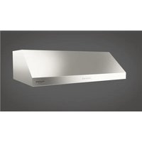
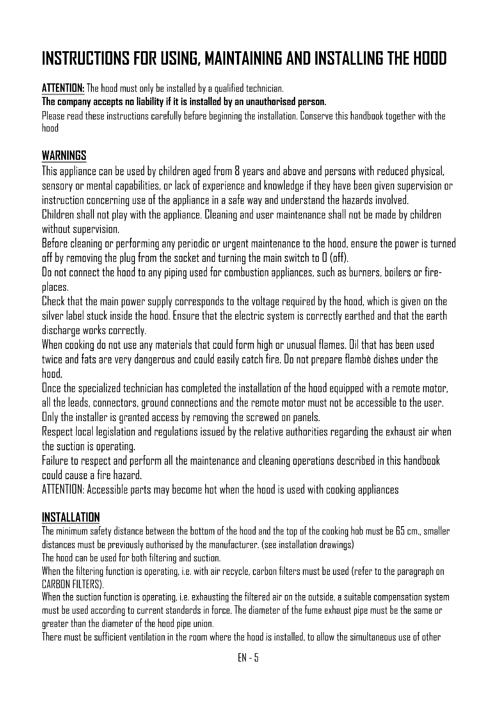
INSTRUCTIONS FOR USING, MAINTAINING AND INSTALLING THE HOOD
ATTENTION: The hood must only be installed by a qualified technician.
The company accepts no liability if it is installed by an unauthorised person.
Please read these instructions carefully before beginning the installation. Conserve this handbook together with the hood
WARNINGS
This appliance can be used by children aged from 8 years and above and persons with reduced physical, sensory or mental capabilities, or lack of experience and knowledge if they have been given supervision or instruction concerning use of the appliance in a safe way and understand the hazards involved.
Children shall not play with the appliance. Cleaning and user maintenance shall not be made by children without supervision.
Before cleaning or performing any periodic or urgent maintenance to the hood, ensure the power is turned off by removing the plug from the socket and turning the main switch to 0 (off).
Do not connect the hood to any piping used for combustion appliances, such as burners, boilers or fireplaces.
Check that the main power supply corresponds to the voltage required by the hood, which is given on the silver label stuck inside the hood. Ensure that the electric system is correctly earthed and that the earth discharge works correctly.
When cooking do not use any materials that could form high or unusual flames. Oil that has been used twice and fats are very dangerous and could easily catch fire. Do not prepare flambè dishes under the hood.
Once the specialized technician has completed the installation of the hood equipped with a remote motor, all the leads, connectors, ground connections and the remote motor must not be accessible to the user. Only the installer is granted access by removing the screwed on panels.
Respect local legislation and regulations issued by the relative authorities regarding the exhaust air when the suction is operating.
Failure to respect and perform all the maintenance and cleaning operations described in this handbook could cause a fire hazard.
ATTENTION: Accessible parts may become hot when the hood is used with cooking appliances
INSTALLATION
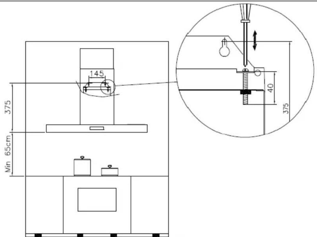
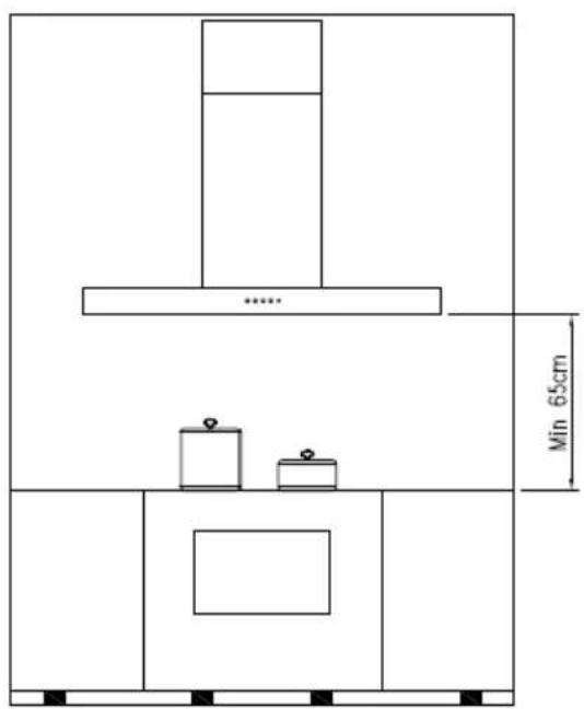
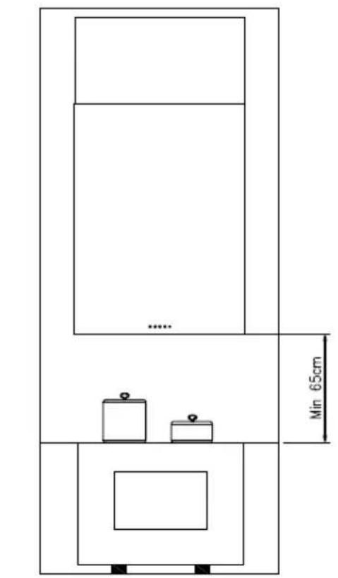
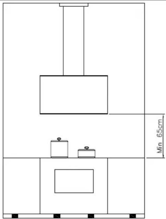
The minimum safety distance between the bottom of the hood and the top of the cooking hob must be 65 cm., smaller distances must be previously authorised by the manufacturer. (see installation drawings)
The hood can be used for both filtering and suction.
When the filtering function is operating, i.e. with air recycle, carbon filters must be used (refer to the paragraph on CARBON FILTERS).
When the suction function is operating, i.e. exhausting the filtered air on the outside, a suitable compensation system must be used according to current standards in force. The diameter of the fume exhaust pipe must be the same or greater than the diameter of the hood pipe union.
There must be sufficient ventilation in the room where the hood is installed, to allow the simultaneous use of other
appliances that use gas or other fuel.
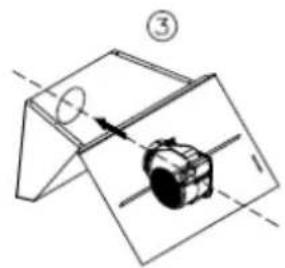
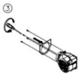
Hoods equipped for remote motors
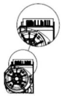
The hoods equipped for remote motors have a specific connector for the remote motor lead connection. The connector is situated inside the hood. Pass the remote motor lead into the hood through the aperture in the hood itself (usually near the fume exit hole) and join the two connectors. Refer to the figures in the remote motor instruction book when performing this operation.
Hoods without motor (Art.*0***) must only be installed and connected with extraction units with a max. output of 640W, as supplied and indicated by the manufacturer.
Once the specialized technician has completed the installation of the hood equipped with a remote motor, all the leads, connectors, ground connections and the remote motor must not be accessible to the user. Only the installer is granted access by removing the screwed on panels.
ASSEMBLY INSTRUCTIONS
Attention: Before proceeding with the installation, make sure that the screws and the anchors already supplied, are suitable for the type of wall the hood must be fixed to.
To assemble the hood use the accessories that are supplied and follow the instructions given in the enclosed handbook.
ELECTRIC WIRING
The electric wiring must be performed by a specialised electrician fully respecting current standards and legislation in force.
Check that the power supply corresponds to the voltage requested by the hood, which is given on the silver label stuck inside the hood.
Ensure that the wiring system conforms to current standards and the earth discharge works efficiently.
Pay special attention to the hood power cable, ensure that it does not pass through any holes without a cable clamp. For direct connection to the electrical mains is necessary to provide a device that ensures disconnection from the electrical mains, with an opening distance of the contacts that allows the complete disconnection under the conditions of overvoltage category III, in accordance with the rules of installation.
The plug or omnipolar switch must be accessible when the unit is installed
If the power cord is damaged, it must be replaced by a special cord or assembly available from the manufacturer or its service agent. The cable used must be of type H05VV-F 3 x 0.75 mm2 minimum cross-section.
The manufacturer declines all responsibility if the current accident prevention standards in force are not respected, which are needed for the wiring system to operate correctly
CONTROLS
SOFT TOUCH CONTROL (Fig. 1)
There are four soft touch buttons on this version and a variable colour led (green min. speed, red max. speed).
One button for turning the lights on and off.
One button for turning on at 2nd speed and for turning the motor off.
N.B. If this button is kept depressed for more than three seconds, the automatic function is activated to turn the hood off function after 10 minutes, the led flashes slowly.
Two buttons + and - for increasing and reducing the motor speed. At the 4th motor speed (intense) the led flashes quickly and after 5 minutes the 2nd speed is automatically set.
DIGITAL CONTROLS \ TOUCH CONTROLS (Fig. 2)
In this version there are five soft touch buttons and a display
One button for turning the lights on and off.
One button for turning on at 2nd speed and for turning the motor off.
Two buttons + and - for increasing and decreasing the motor speed. At the 4th motor speed (intense) the number on the display flashes and after 5 minutes the 2nd speed is automatically set.
A TIMER button for turning the motor off after 10 minutes. When the timer is activated, the number on the display flashes.
Special functions:
After 100 hours use, a 0 or a letter A will start flashing on the DISPLAY to remind the user to clean the metal filters. After washing the metal filters, reset the hour meter by pressing the TIMER button for more than three seconds with the hood turned off.
When the hour meter has been reset a dash appears on the display, with the hood turned off.
ROTARY CONTROL (Fig.3)
In the rotary control version there are three knobs:
One knob for switching light decorative on and off
One knob for switching lights on and off
One knob for speed selection (1 ^, 2 ^, 3 ^, 4 ^, ) and turning the motor off.
SOFT TOUCH CONTROL BACKLIT (Fig. 4)
There are six buttons on this version:
One for turning the motor on at 1st speed and for turning it off.
One for turning it on at 2nd speed.
One for turning it on at 3rd speed.
One for turning it on at 4th speed. At the 4th motor speed (intense) the led flashes quickly and after 5 minutes the 2nd speed is automatically set.
TIMER button for turning the motor off after 10 minutes.
One for turning the lights on and off.
USE AND MAINTENANCE
Before beginning any sort of cleaning or maintenance work, turn power off to the hood by turning the main switch to 0 (OFF).
Changing the light bulbs
12V halogen G4 attachment: Use a screwdriver to unscrew the glass support ring (Fig. 5). Remove the glass and change the light bulb with another identical.
Replace the protective glass and screw back the ring. The light bulbs can be purchased in any electrical supply shop. Dichroic lamp G4 attachment: Use a screwdriver to remove and change the dichroic lamp with another identical (Fig. 6).
LED spotlight replacement should only be carried out by qualified technicians using only original spare parts.
Cleaning the metal filters:
The metal filters fitted in the hood should be washed every 2-3 months, depending on how much the hood is used, using hot water and a liquid detergent that is not too aggressive.
The metal filters can be removed by the special handle, unhooking the front part of the filter and pulling it downwards (Fig. 7)
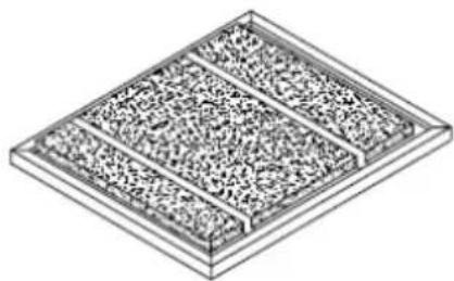
Carbon filters
If the hood is used with an internal recycle filtering system, then active carbon filters must be used.
The active carbon in the filters traps the cooking smells. To remove and change the filters, refer to fig. 8.
POLYESTER carbon filters cannot be reused or washed and must be periodically changed (every 4 months if the hood is used for 2 hours every day). Saturate filters could be a fire hazard.
Depending on the hood model, the carbon filters are round or rectangular.
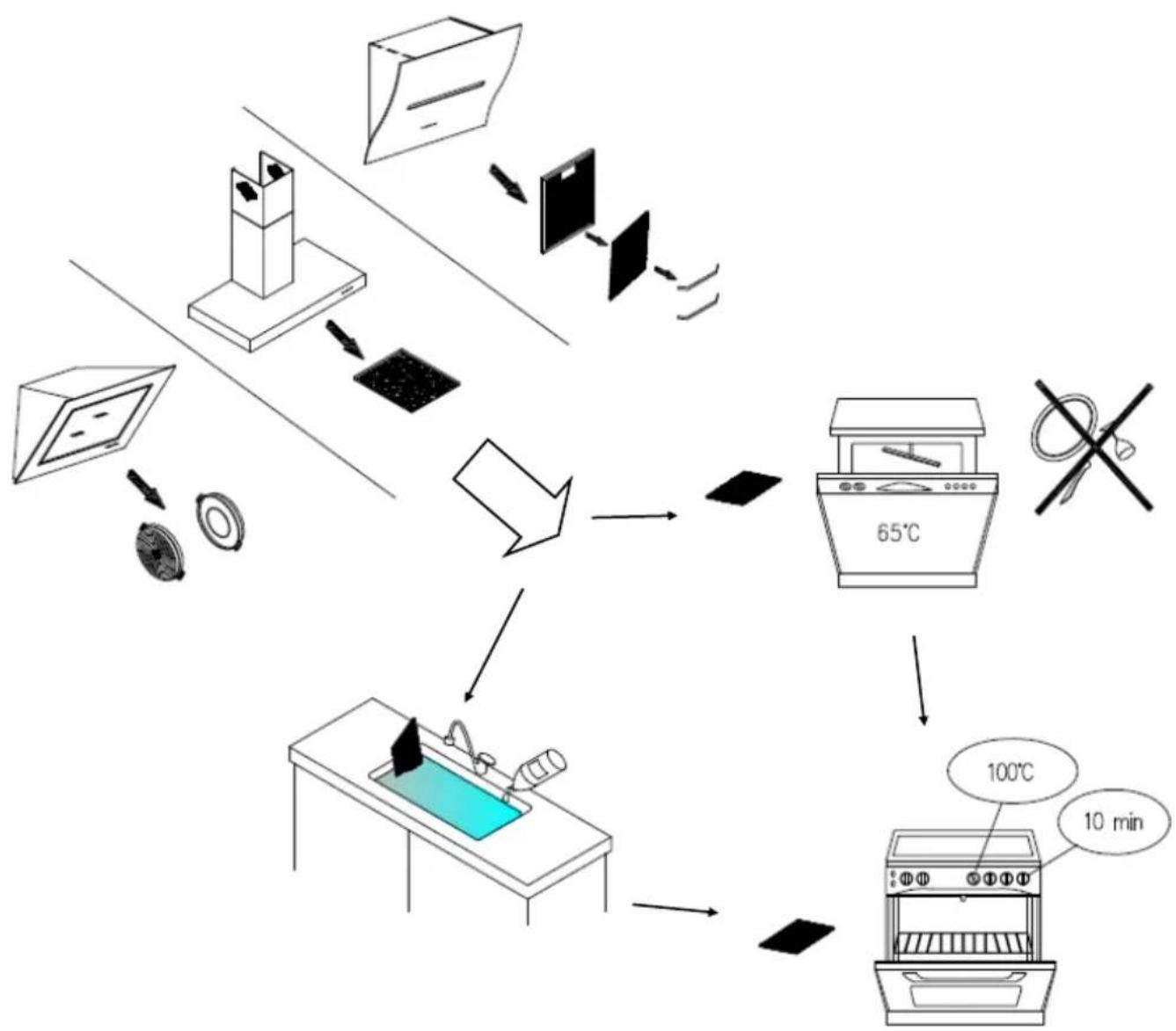
LONG LIFE carbon filter can be cleaned and reactivated. The filter should be cleaned every other month if used normally. The filter is best cleaned in a dishwasher at the highest temperature using normal washer detergent. The filter should be washed on its own to prevent particles of food from fastening in it and then causing an unpleasant smell later on. To reactivate the carbon the filter should be dried in the oven. Chose upper/ lower heat and maximum 100°C and try the filter for 10 minutes. The filter must be changed when it no longer absorbs the cooking smells sufficiently. (fig.9)
Cleaning the hood
The surfaces of the hood should be cleaned frequently, to avoid the risk of having to remove built up and encrusted deposits and stains. For the painted or copper plated hoods just use a soft cloth with warm water and a neutral detergent. Do not pour the detergent directly onto the hood or use powdery or abrasive products. For the stainless steel hood, use special products and cloths for satin finish stainless steel (not abrasive, corrosive detergents or detergents containing chloride), ensuring to clean in the same direction as the satin finish. Do not use aggressive products, chemical solvents or derivatives of oil distillates that could leave oily traces which could cause oxidation and polymerisation.
Condensation in the hood
Induction or glass ceramic hobs heat food up very quickly, creating cooking steam before the glass or steel surface of the hood has heated up, which causes condensation on the hood that then drips. Another cause for condensation could be that the fume pipe is not the size we recommend (see INSTALLATION). The steam that remains inside the hood while it is cooling down condensates and drips. Therefore it is advisable to turn the hood on ten minutes before starting to cook and when you have finished, leave it on so that all the fumes in the pipe are expelled.
Furthermore, it is important to clean the filters frequently and if they are worn they should be replaced (see CLEANING THE METAL FILTERS).
The manufacturer accepts no responsibility for damage to the surface of the hood due to failure to respect these instructions.
BEDIENUNGS-, WARTUNGS- UND INSTALLATIONSHANDBUCH ABZUGSHAUBE
natural_image
Diagram of a device with internal components and directional arrows, no visible text or symbolsMOD. RR90 - RR120
RB60 - RB90
FLH80 - FQLHI60
natural_image
Isometric view of a rectangular metal tray filled with granular material (no text or symbols)FIG. 8
flowchart
graph TD
    A["65°C"] --> B["100°C"]
    B --> C["10 min"]
    D["Refrigerator with fan blade"] --> E["Refrigerator with cloth blade"]
    E --> F["Refrigerator with flat blade"]
    F --> G["Refrigerator with flat blade"]
    G --> H["Refrigerator with flat blade"]
    H --> I["Refrigerator with flat blade"]
    I --> J["Refrigerator with flat blade"]
    J --> K["Refrigerator with flat blade"]
    K --> L["Refrigerator with flat blade"]
    L --> M["Refrigerator with flat blade"]
    M --> N["Refrigerator with flat blade"]
    N --> O["Refrigerator with flat blade"]
    O --> P["Refrigerator with flat blade"]
    P --> Q["Refrigerator with flat blade"]
    Q --> R["Refrigerator with flat blade"]
    R --> S["Refrigerator with flat blade"]
    S --> T["Refrigerator with flat blade"]
    T --> U["Refrigerator with flat blade"]
    U --> V["Refrigerator with flat blade"]
    V --> W["Refrigerator with flat blade"]
    W --> X["Refrigerator with flat blade"]
    X --> Y["Refrigerator with flat blade"]
    Y --> Z["Refrigerator with flat blade"]
    Z --> AA["Refrigerator with flat blade"]
    AA --> AB["Refrigerator with flat blade"]
    AB --> AC["Refrigerator with flat blade"]
    AC --> AD["Refrigerator with flat blade"]
    AD --> AE["Refrigerator with flat blade"]
    AE --> AF["Refrigerator with flat blade"]
    AF --> AG["Refrigerator with flat blade"]
    AG --> AH["Refrigerator with flat blade"]
    AH --> AI["Refrigerator with flat blade"]
    AI --> AJ["Refrigerator with flat blade"]
    AJ --> AK["Refrigerator with flat blade"]
    AK --> AL["Refrigerator with flat blade"]
    AL --> AM["Refrigerator with flat blade"]
    AM --> AN["Refrigerator with flat blade"]
    AN --> AO["Refrigerator with flat blade"]
    AO --> AP["Refrigerator with flat blade"]
    AP --> AQ["Refrigerator with flat blade"]
    AQ --> AR["Refrigerator with flat blade"]
    AR --> AS["Refrigerator with flat blade"]
    AS --> AT["Refrigerator with flat blade"]
    AT --> AU["Refrigerator with flat blade"]
    AU --> AV["Refrigerator with flat blade"]
    AV --> AW["Refrigerator with flat blade"]
    AW --> AX["Refrigerator with flat blade"]
    AX --> AY["Refrigerator with flat blade"]
FIG. 9
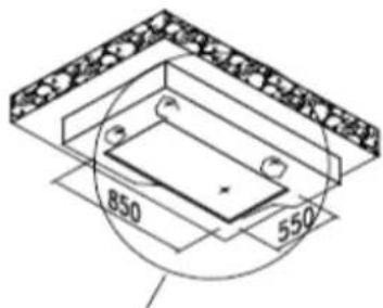
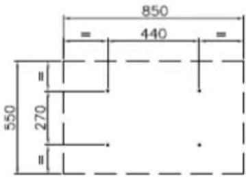
SHC 9011 - SHC 12011
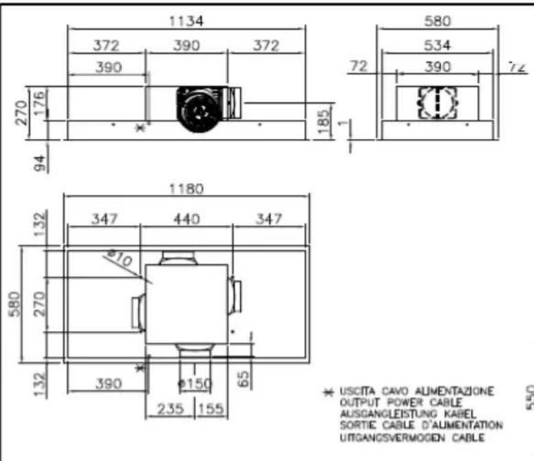
* USCITA CAVO ALIMENTAZIONE OUTPUT POWER CABLE AUSGANGLEISTUNG KABEL SORTIE CABLE D'ALIMENTATION UITGANGSVERMOGEN CABLE
SHC 12011 RC X
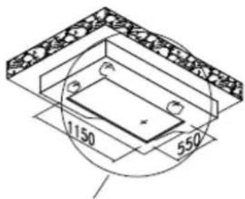
text_image
1150 550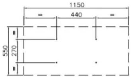
text_image
1150 = 440 = 550 = 270 =SHC 12011 (31Kg)
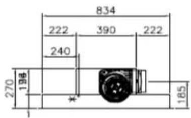
text_image
834 222 390 222 240 270 198 185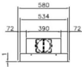
text_image
580 534 72 390 72 -1 1SHC 9011 RC X
text_image
850 550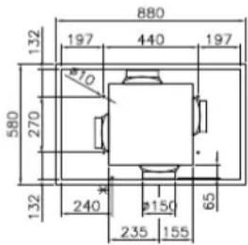
text_image
880 132 197 440 197 580 270 240 150 65 235 155 132USCITA CAVO ALIMENTAZIONE OUTPUT POWER CABLE AUSGANGLEISTUNG KABEL SORTIE CABLE D'ALIMENTATION UITGANGSVERMOGEN CABLE
text_image
850 = 440 = 550 = 270 . = .SHC 9011 (23Kg)
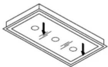
natural_image
Isometric diagram of a rectangular plate with internal circular features and downward arrows indicating direction (no text or symbols)Per aprire tirare qui simultaneamente Please pull here in the same time to open Zlehen sle hier
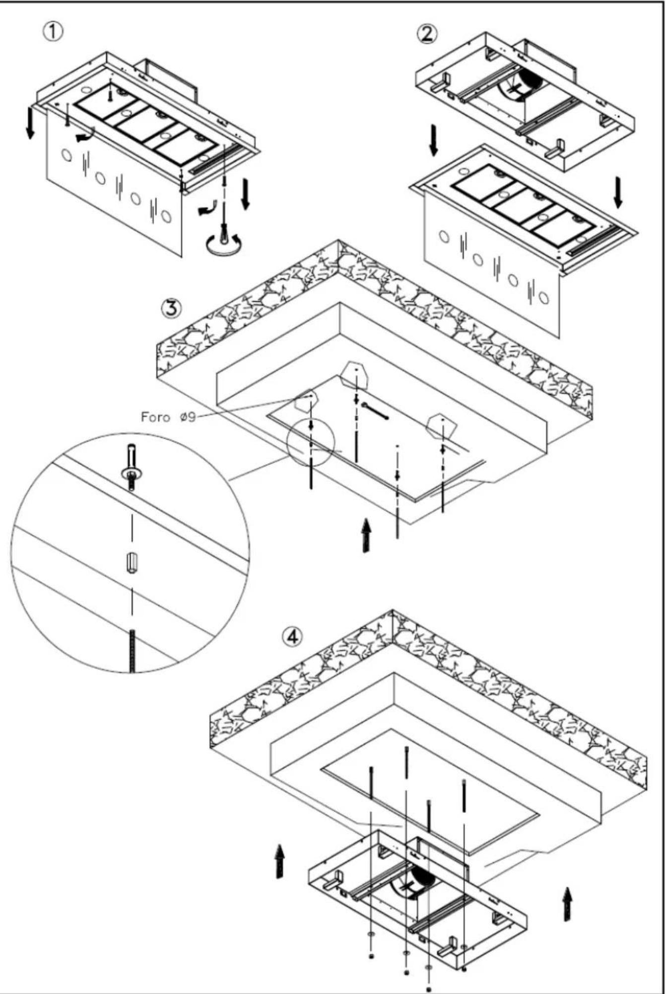
text_image
Technical diagram illustrating four sequential installation steps of a rectangular panel or enclosure, labeled ① to ④ with annotations and a circular detail view.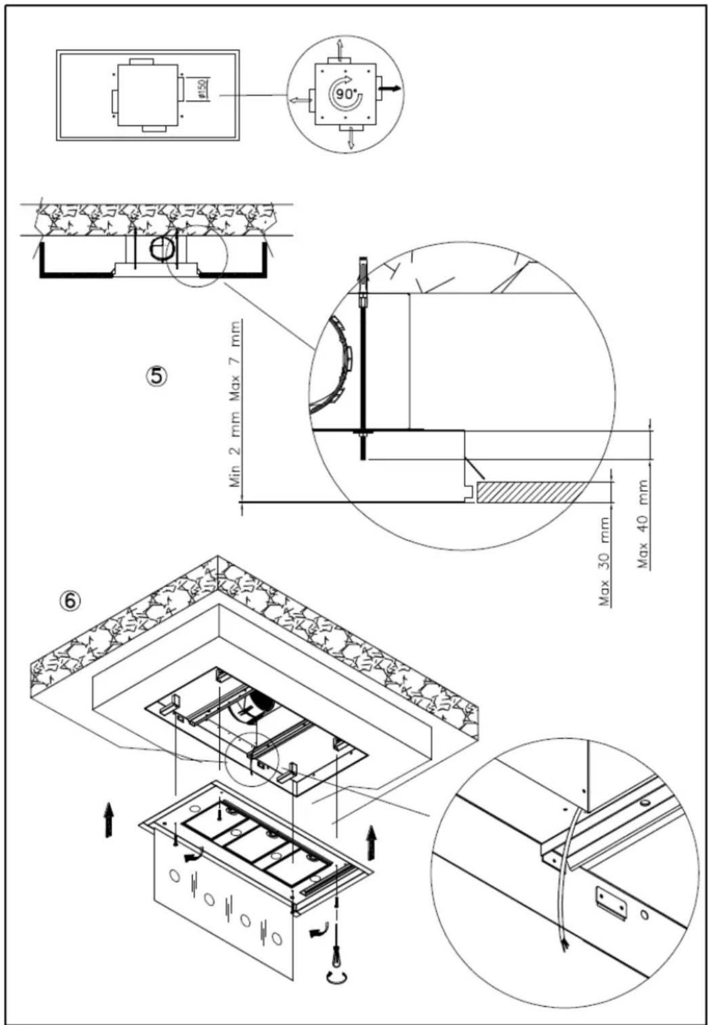
text_image
90° Min 2 mm Max 7 mm Max 30 mm Max 40 mm ⑤ ⑥CHB 6012 - CHB 9012
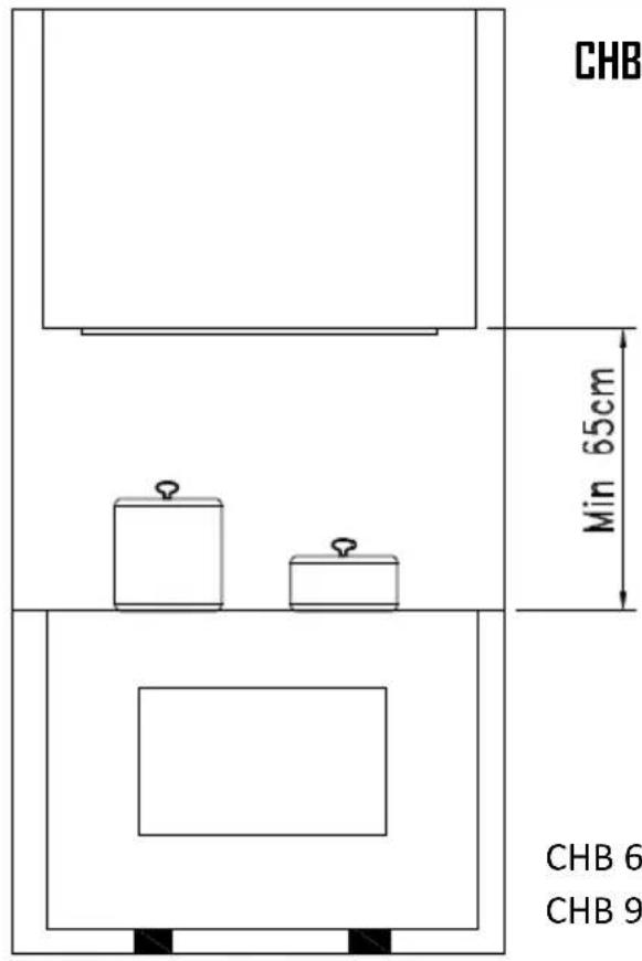
text_image
CHB Min 65cm CHB 6 CHB 9CHB 6012 RC X - CHB 9012 RC X

text_image
526-726 260 21 534-734 272CHB 6012 (10Kg)
CHB 9012 (11Kg)
natural_image
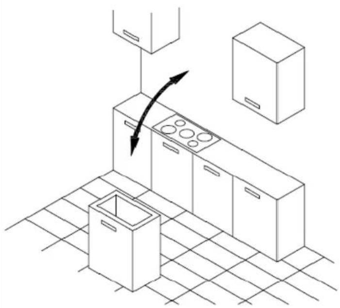
Isometric line drawing of a kitchen interior with cabinets, a trash bin, and a curved arrow indicating rotation (no text or symbols)text_image
Technical diagram of an appliance with labeled parts and a magnified inset showing internal components.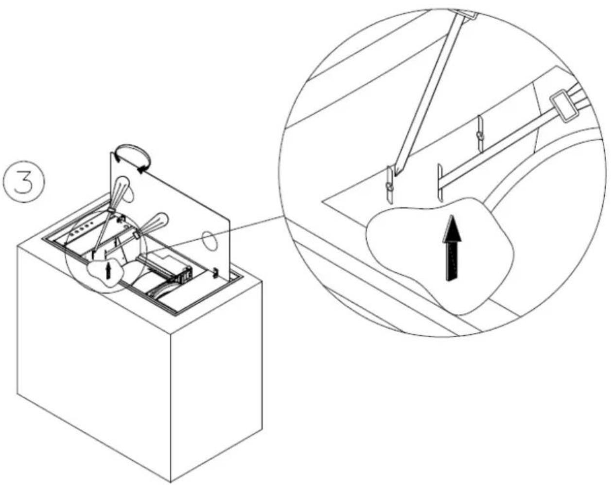
text_image
Technical diagram showing a mechanical device with internal components and a magnified view of the internal structure with directional arrows.FLH 800

text_image
400 35 360 Min55-60cm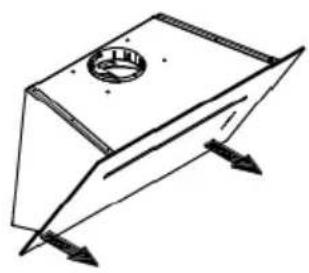
natural_image
Simple line drawing of a mechanical component with arrows indicating direction (no text or symbols)Per aprire tirare qui simultaneamente Please pull here in the same time to open Ziehen sie hier
FLH 800 (17kg)
natural_image
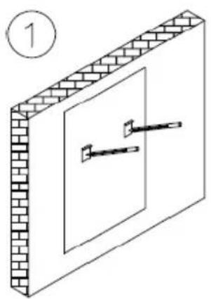
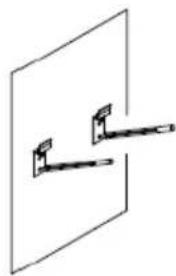
Isometric diagram of a brick wall with a door and two handrails, no text or symbols present②
natural_image
Simple line drawing of two vertical bars mounted on a flat surface, no text or symbols present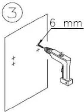
text_image
③ 6 mm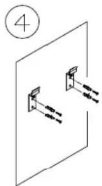
natural_image
Simple line drawing of two wall-mounted sensors or sensors mounted on a panel, with no text or symbols present.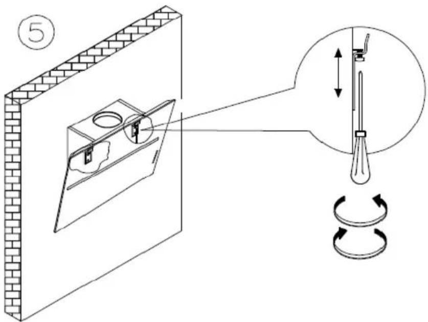
text_image
Technical diagram illustrating a mechanical assembly with labeled components and motion indicators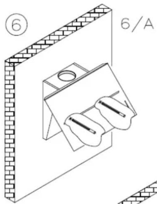
text_image
⑥ 6/A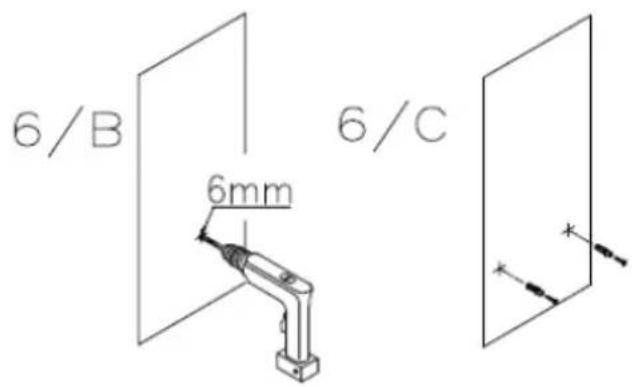
text_image
6/B 6mm 6/C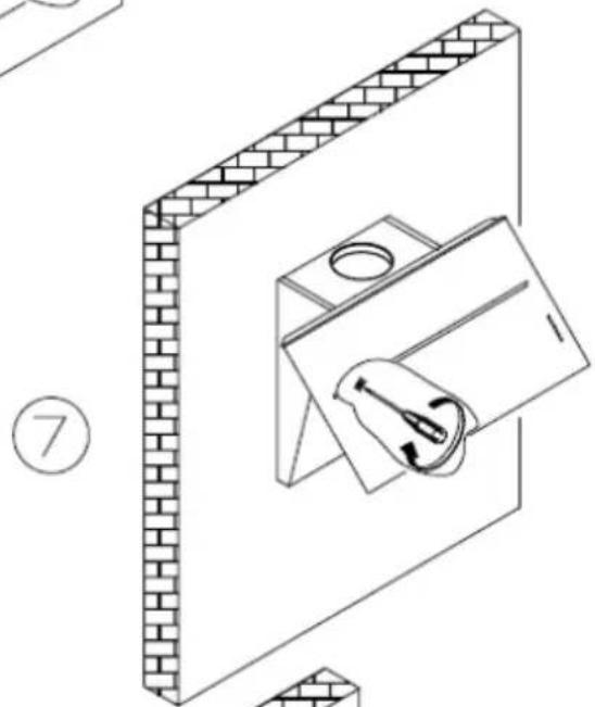
natural_image
Isometric line drawing of a wall-mounted device mounted on a brick wall, with no visible text or symbols.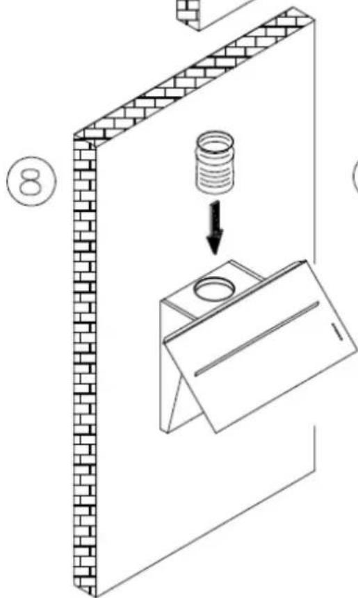
text_image
Technical diagram showing a mechanical assembly with a spring-loaded component and a housing, labeled with number 8.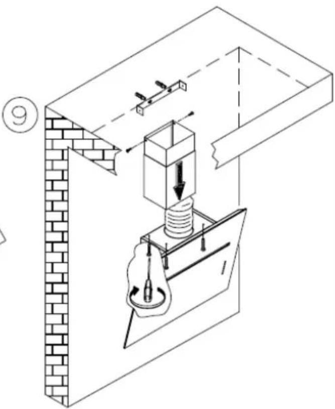
text_image
Technical diagram showing a mechanical assembly with labeled components and directional arrows indicating motion or force.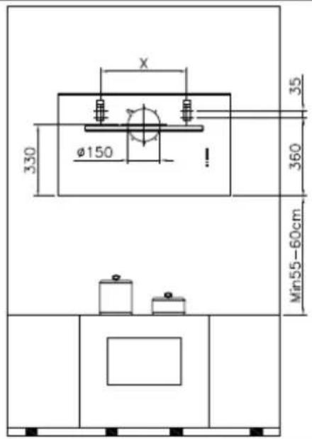
text_image
330 Ø150 X 35 360 Min55-60cm
text_image
Min55-60cm 25 FLH 800 (17kg)MOTOR A
natural_image
Technical diagram of a mechanical assembly with two circular views showing internal components (no text or labels)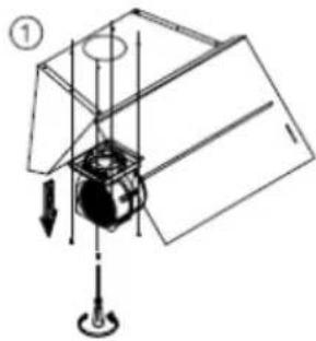
natural_image
Technical diagram of a mechanical assembly with no visible text or symbols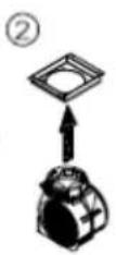
natural_image
Technical line drawing of a mechanical assembly with no visible text or symbols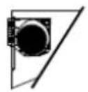
MOTOR B
natural_image
Mechanical assembly diagram showing two circular views of a gear or cam mechanism (no text or labels)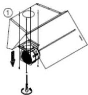
text_image
Technical diagram showing a mechanical assembly with labeled components and directional arrows indicating motion or force.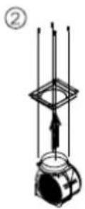
natural_image
Mechanical diagram showing a lever mechanism with rotating components and motion arrows (no text or symbols)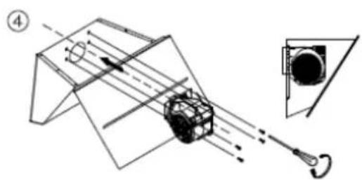
natural_image
Technical diagram of a mechanical assembly with a gear and housing, showing internal components and motion lines (no text or symbols)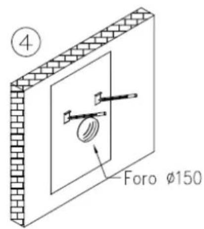
text_image
④ Foro Ø150
natural_image
Simple line drawing of a wall-mounted tool with a circular component, no text or symbols present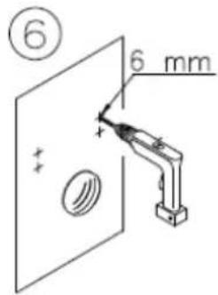
text_image
⑥ 6 mm
natural_image
Diagram showing two wall-mounted fixtures mounted on a panel, with no visible text or symbols.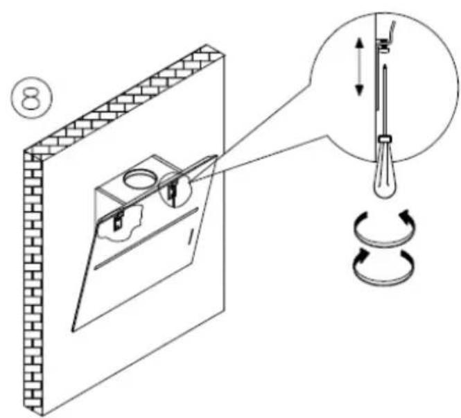
text_image
Technical diagram showing a mechanical assembly with labeled components and motion indicators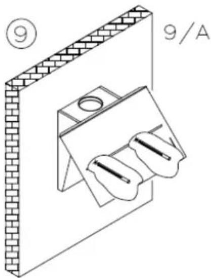
text_image
⑨ 9/A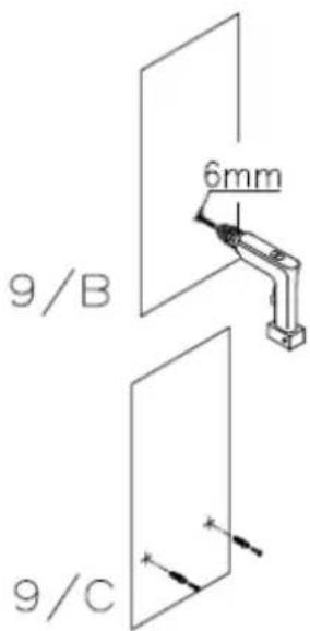
text_image
6mm 9/B 9/C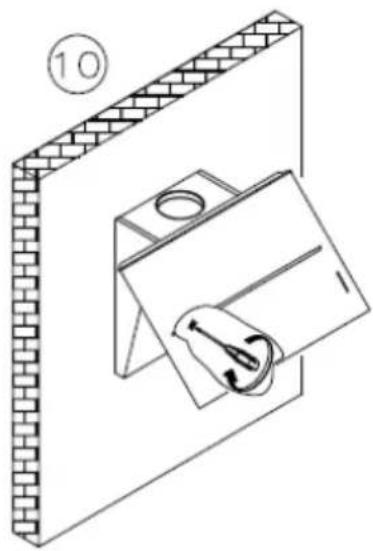
natural_image
Technical line drawing of a mechanical assembly with brick wall and housing (no text or symbols)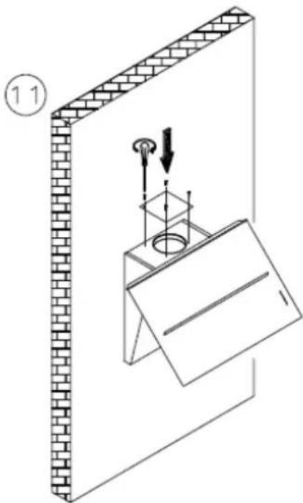
natural_image
Technical diagram of a mechanical assembly with a bracket and mounting base, showing force application and dimension lines (no text or symbols)FQH 900 - FQH 1200
text_image
375 Min 65cm 145 40 375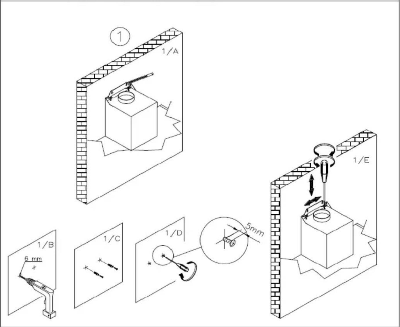
text_image
① 1/A 1/B 6 mm 1/C 1/D 5mm 1/E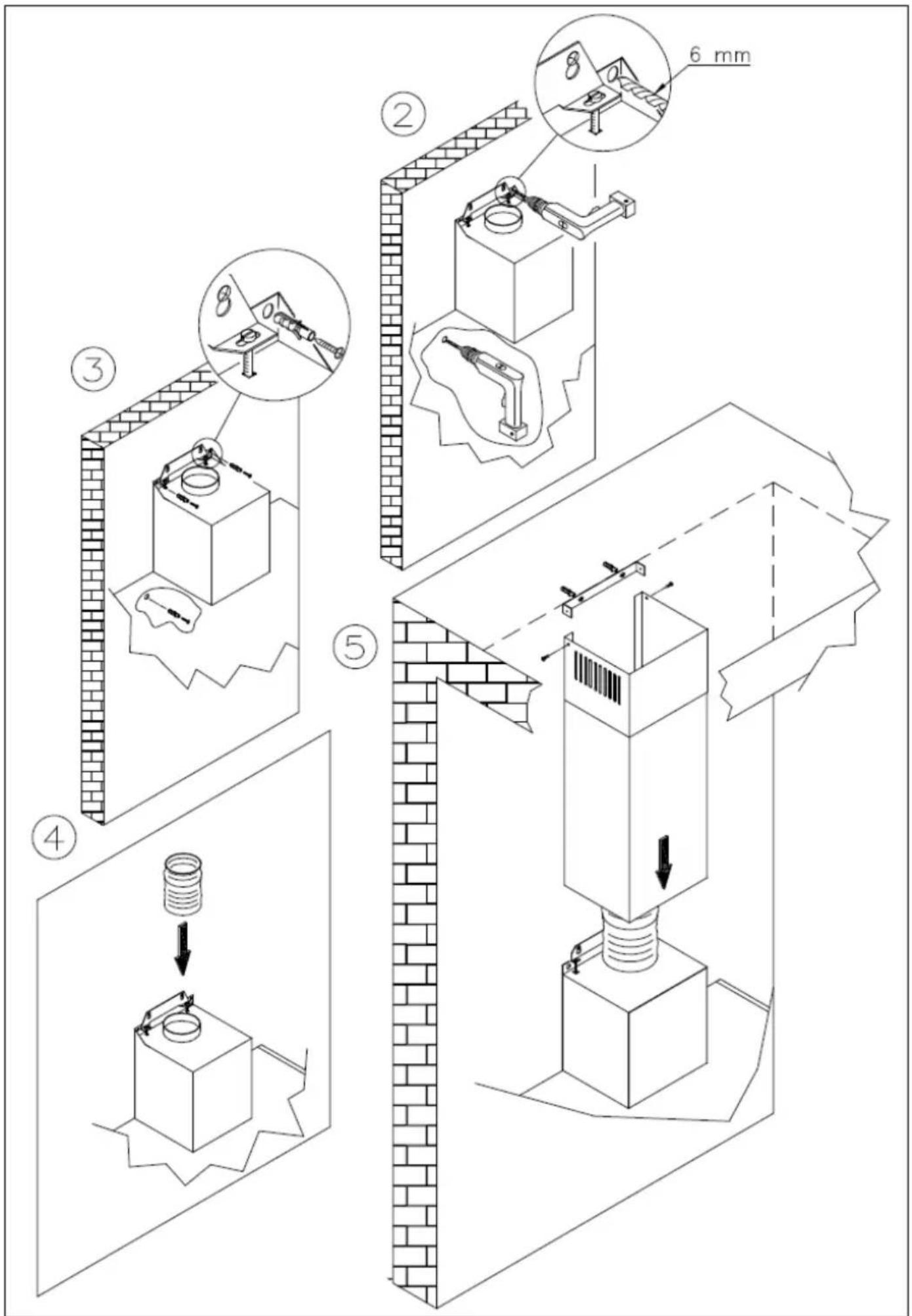
text_image
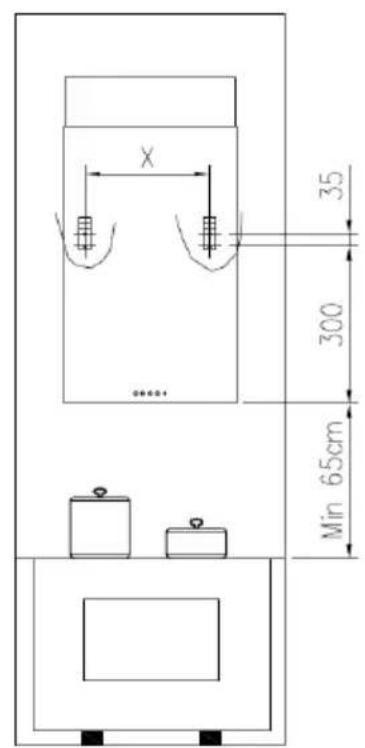
Technical diagram illustrating a mechanical assembly with numbered components and magnified views, including a 6 mm scale indicator.FCH 600
text_image
X 35 300 Min 65cmFCH 600 (18Kg) X=290
natural_image
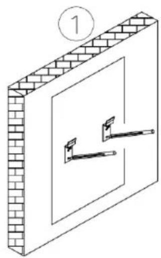
Isometric line drawing of a brick wall with a door and two tools, no text or symbols present②
text_image
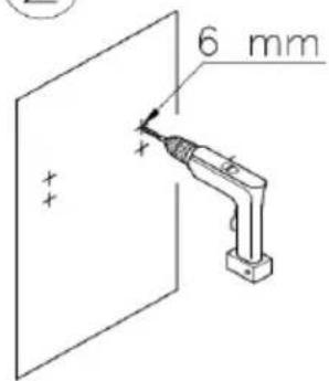
6 mm③
natural_image
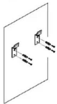
Pure diagram of two vertical supports with diagonal lines extending outward, no text or symbols present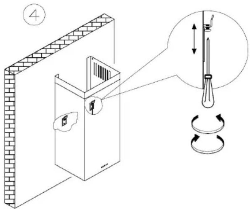
text_image
Technical diagram showing a door assembly with labeled components and a mechanical device, including rotation arrows.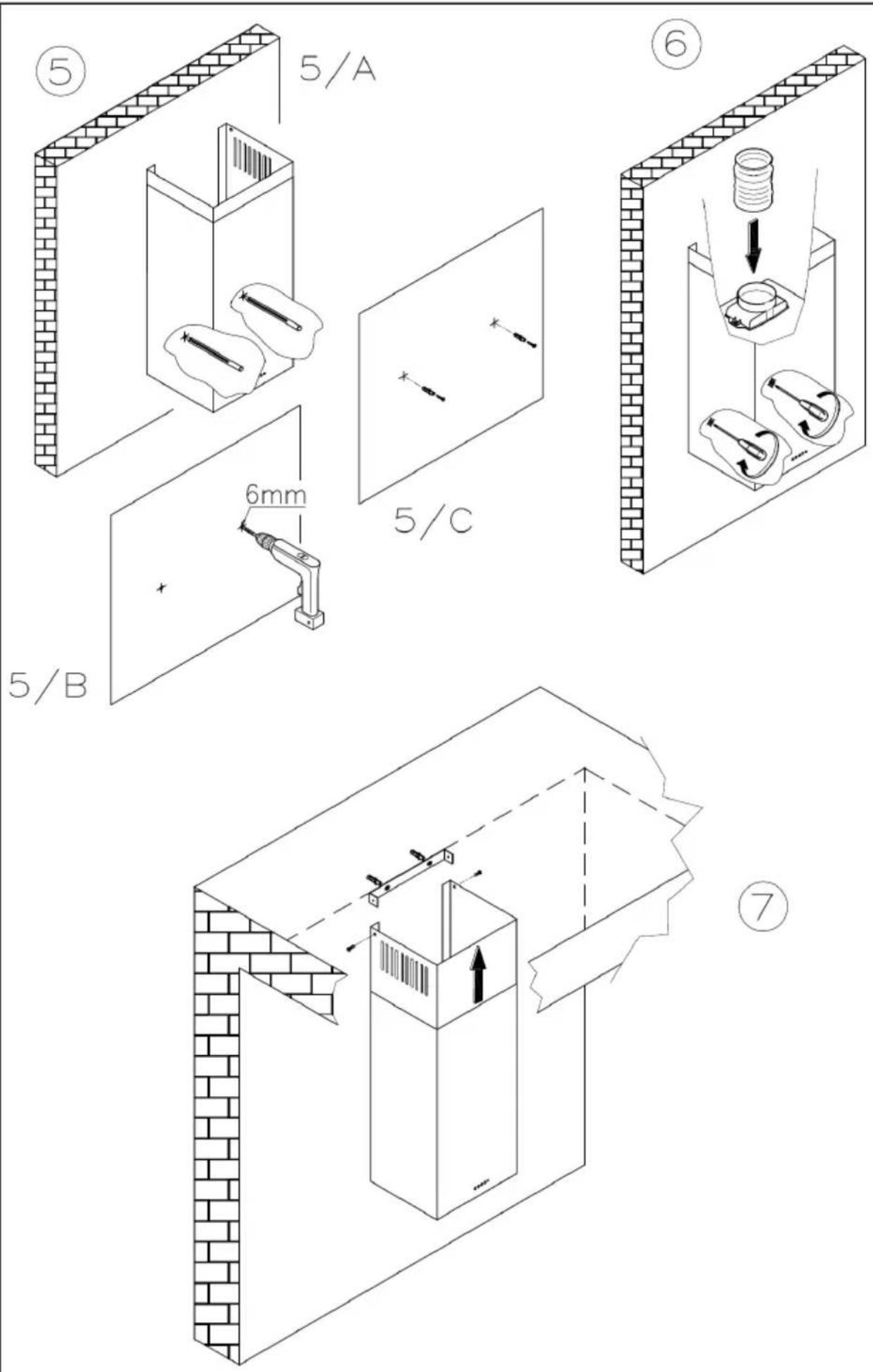
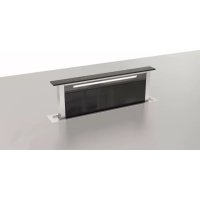
FQHI 900 - FQHI 1200
text_image
...... Min 65cmSLIM ISOLA 90/120 (38/41kg)
text_image
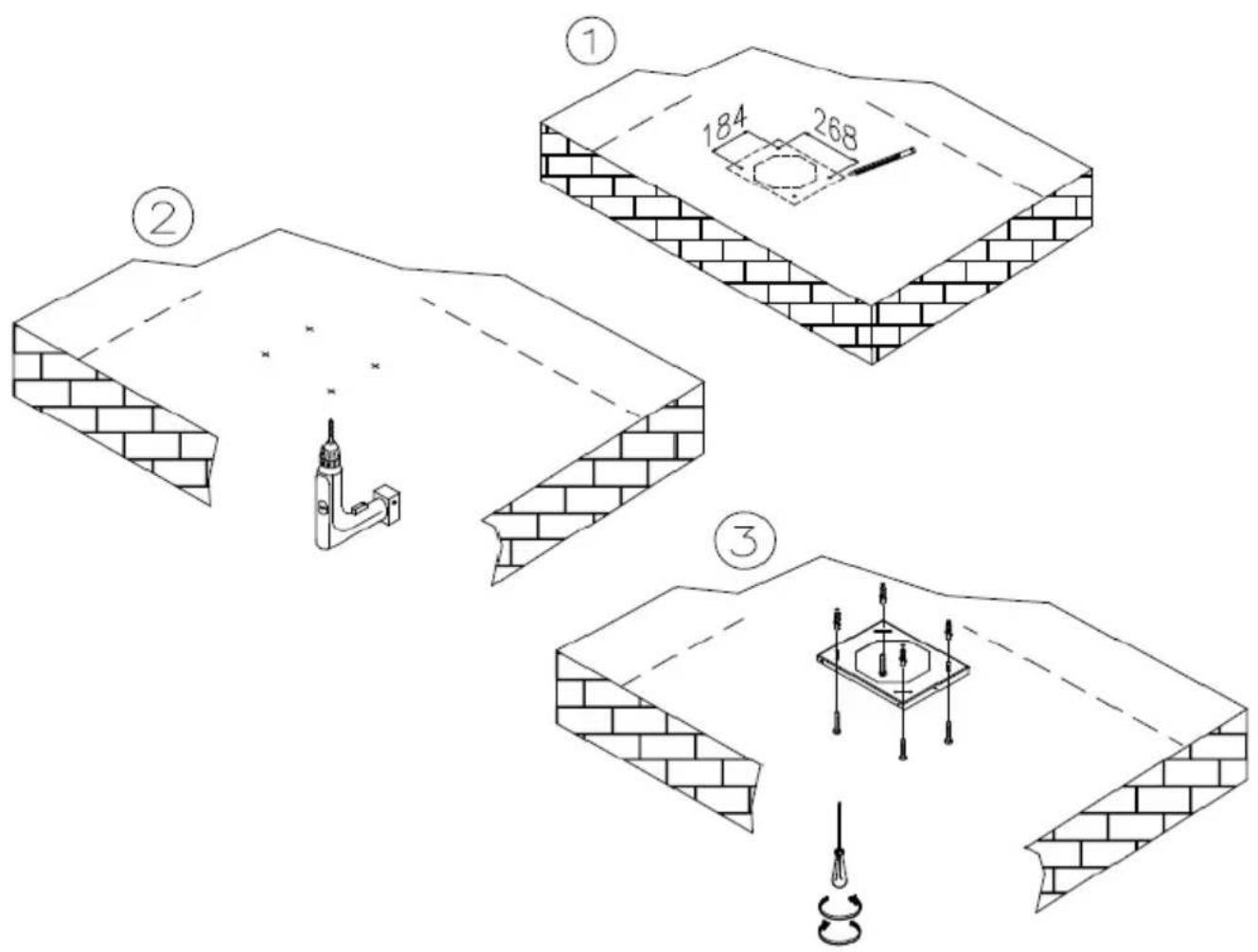
Technical diagram showing three steps of brick wall installation with numbered components and dimension annotations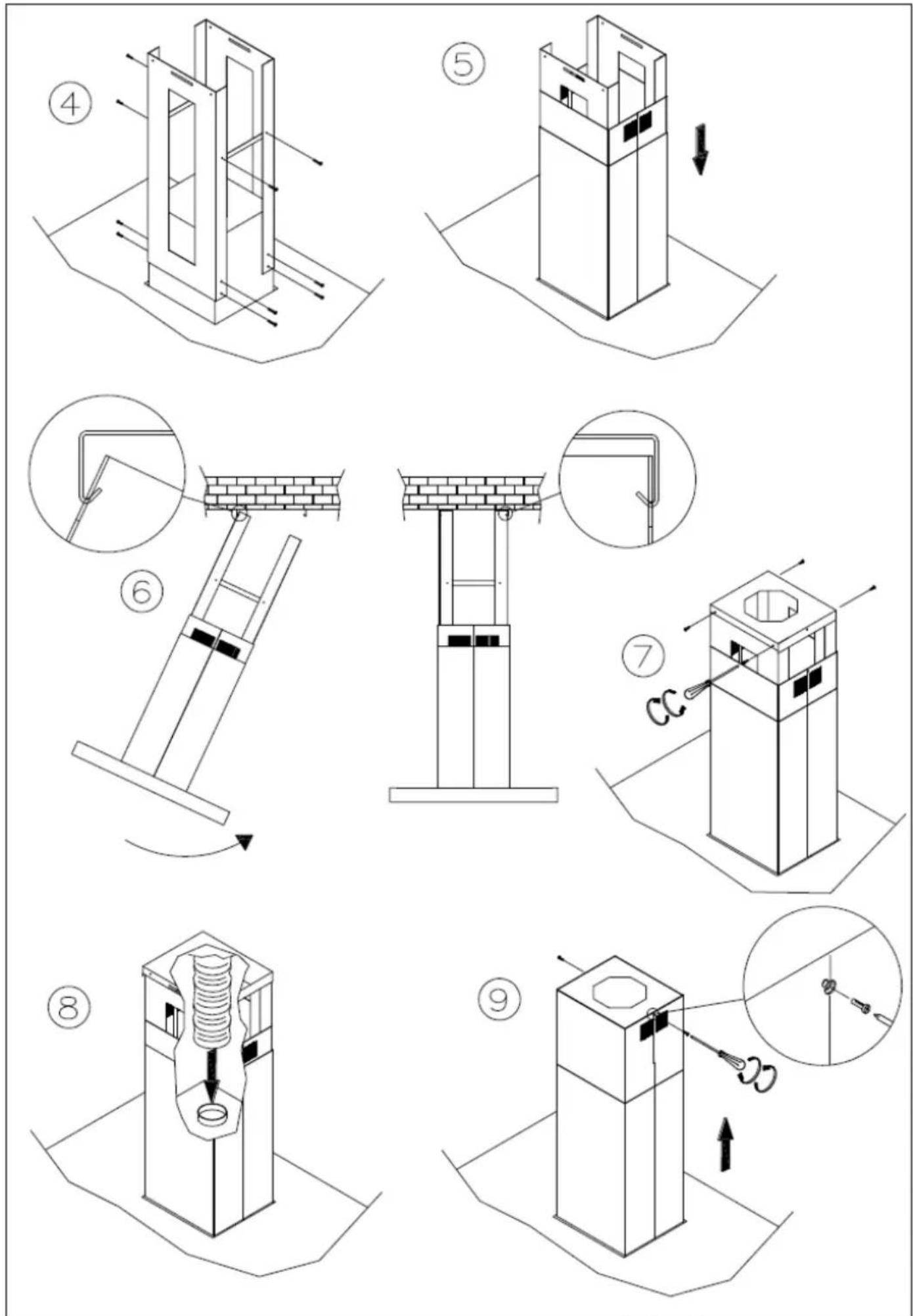
FCHI 900
text_image
...... Min 65cmFCHI 900 (49Kg)
text_image
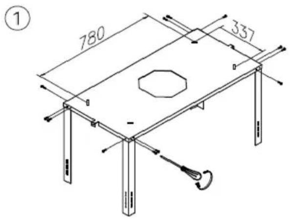
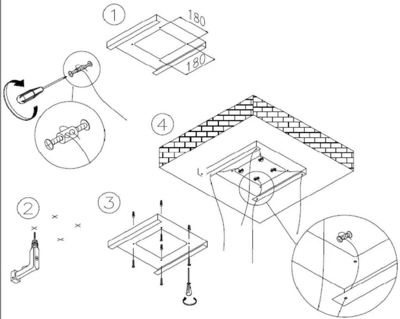
① 780 337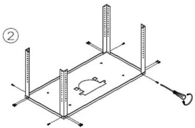
natural_image
Technical line drawing of a structural frame with supports and a curved component, no text or symbols present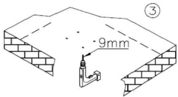
text_image
9mm ③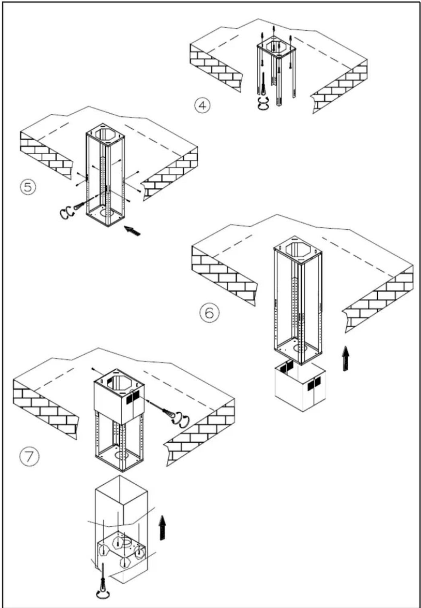
text_image
Technical diagram illustrating the step-by-step installation of a structural frame with labeled components and directional arrows.FQLHI 600
text_image
Min 65cmFQLHI 600 (21Kg)
text_image
Technical diagram illustrating a mechanical assembly with numbered components and cross-sectional views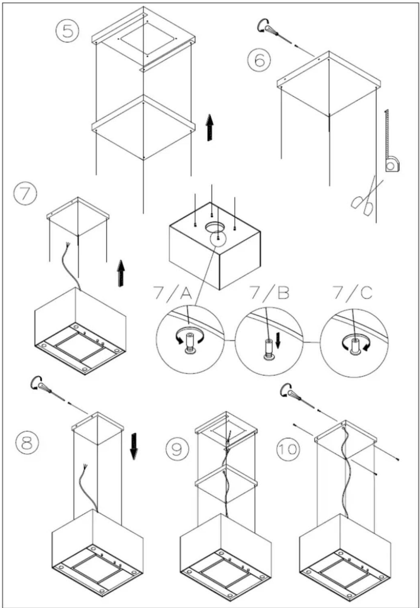
text_image
Technical diagram illustrating 10 steps of a mechanical assembly or assembly process, labeled with numbered instructions and component diagrams.INDICE - INDEX:
SHC 9011, SHC 12011.... pg.28
CHB 6012, CHB 9012.... pg.31
FLH 800.... pg.33
FQH 900, FQH 1200.... pg.37
FCH 600.... pg.39
FQHI 900, FQHI 1200.... pg.41
FCHI 900.... pg.43
FQLHI 600.... pg.45
FULGOR
MILANO
3
Anni di
garanzia
SERVIZIO ASSISTENZA TECNICA
199.151.195
www.fulgor-milano.com - info@fulgor-milano.com