
HLTD600AEW - Tumble drier HAIER - Free user manual and instructions
Find the device manual for free HLTD600AEW HAIER in PDF.
| Product Type | Dryer |
| Brand | Haier |
| Model | HLTD600AEW |
| Capacity | Not specified, estimated 6 kg (average load) |
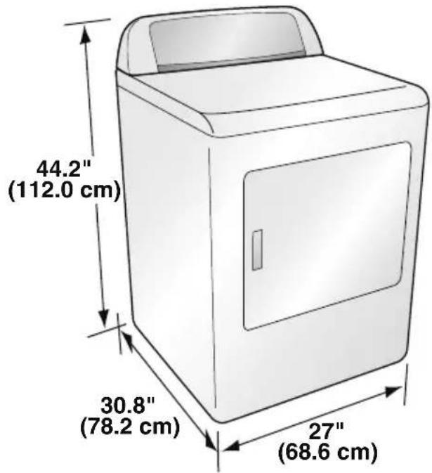
| Dimensions (H x W x D) | 112.0 x 78.2 x 68.6 cm |
| Weight | Not specified, estimated 45 kg |
| Power Supply (Electric) | 120/240 V, 30 A, single-phase 60 Hz |
| Power Supply (Gas) | 120 V, 15 A, single-phase 60 Hz |
| Gas Type (Gas version) | Natural gas (low pressure), convertible to propane |
| Drying Programs | Normal, Delicates, Bulky, Heavy Duty, Towels, Perm Press, Sanitize, Quick Dry, Time Dry, Air Fluff |
| Moisture Sensor | Yes, automatic dry level detection |
| Drying Options | Eco, Anti-wrinkle, Delay Start (up to 24h), Child Lock, Favorite, Temperature Setting (High, Medium, Low, Ultra Low, No Heat) |
| Display | LED, estimated remaining time |
| Interior Light | Yes, automatic drum light |
| Lint Filter | Removable filter, clean before each use, deep clean every 6 months |
| Exhaust Duct Maintenance | Inspect and clean at least every 12 months |
| Safety | Automatic stop if door opened, child lock, thermal fuse, ANSI/UL compliance |
| Door Reversal | Yes, possible (opens left to right by default, reversible) |
| Warranty | 1 year parts and labor; drum warranty 5 years |
| Installation | Outdoor exhaust required, minimum clearances (5" rear, 3" sides) |
Frequently Asked Questions - HLTD600AEW HAIER
User questions about HLTD600AEW HAIER
0 question about this device. Answer the ones you know or ask your own.
Ask a new question about this device
Download the instructions for your Tumble drier in PDF format for free! Find your manual HLTD600AEW - HAIER and take your electronic device back in hand. On this page are published all the documents necessary for the use of your device. HLTD600AEW by HAIER.
USER MANUAL HLTD600AEW HAIER
Gas and Electric Clothes Dryers
natural_image
Line drawing of a simple rectangular box with a lid and front panel (no text or symbols)TABLE OF CONTENTS
IMPORTANT SAFETY INSTRUCTIONS....2
Gas Dryer Precautions 4
General Safety Precautions 5
PARTS AND FEATURES 6
INSTALLATION INSTRUCTIONS....7
Tools Needed 7
Additional Parts Required....8
Location Requirements....8
Electrical & Gas Supply Requirements....10
Gas Supply Connection Requirements....12
Burner Input Requirements....13
Exhaust System Requirements....13
Mobile Home - Additional Requirements....15
STEP BY STEP INSTRUCTIONS....16
Step 1 - Unpack the Dryer....16
Step 2 - Attach a Power Cord to the Dryer (Electric Dryer - U.S. Only) ......16
Step 2 - Connect to a Gas Supply Line (Gas Dryer Only)....19
Step 3 - Connect to an Exhaust System....20
Step 4 - Level the Dryer ....21
Step 5 - Complete the Installation....21
Step 6 - Door Reversal (Optional)....22
CONTROL PANEL AND FEATURES 23
OPERATING INSTRUCTIONS......27
Step 1 - Prepare and Sort Laundry ....27
Step 2 - Clean the Lint Screen ....27
Step 3 - Load the Dryer 27
Step 4 - Start the Dryer....28
USER MAINTENANCE INSTRUCTIONS 29
Cleaning and Maintenance 29
Washing the Lint Screen....29
Removing Accumulated Lint....30
Vacationing Precautions 30
Moving or Storage Preparation 30
TROUBLESHOOTING....31
LIMITED WARRANTY 33
RECORD KEEPING
Thank you for purchasing this Haier product. This user manual will help you get the best performance from your new dryer.
For future reference, record the model and serial number located on back of the dryer, and the date of purchase.
Staple your proof of purchase to this manual to aid in obtaining warranty service if needed.
Model number
Serial number
Date of purchase
IMPORTANT SAFETY INSTRUCTIONS
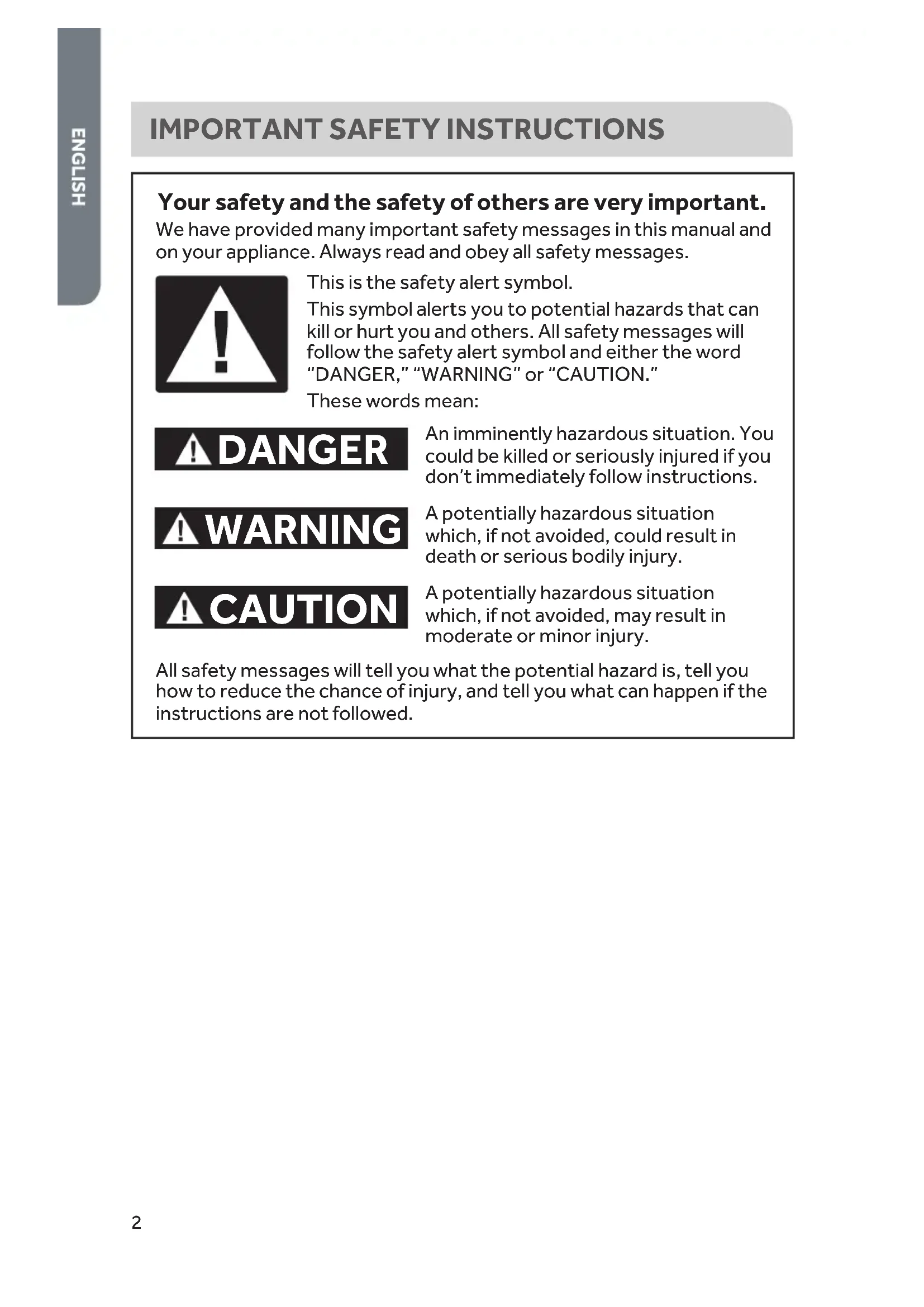
Your safety and the safety of others are very important.
We have provided many important safety messages in this manual and on your appliance. Always read and obey all safety messages.

This is the safety alert symbol.
This symbol alerts you to potential hazards that can kill or hurt you and others. All safety messages will follow the safety alert symbol and either the word "DANGER," "WARNING" or "CAUTION."
These words mean:
! DANGER
An imminently hazardous situation. You could be killed or seriously injured if you don't immediately follow instructions.
WARNING
A potentially hazardous situation which, if not avoided, could result in death or serious bodily injury.
CAUTION
A potentially hazardous situation which, if not avoided, may result in moderate or minor injury.
All safety messages will tell you what the potential hazard is, tell you how to reduce the chance of injury, and tell you what can happen if the instructions are not followed.
WARNING: For your safety, the information in this manual must be followed to minimize the risk of fire or explosion, or to prevent property damage, personal injury, or death.
-Do not store or use gasoline or other flammable vapors and liquids in the vicinity of this or any other appliance.
-WHAT TO DO IF YOU SMELL GAS:
- Do not try to light any appliance.
- Do not touch any electrical switch; do not use any phone in your building.
- Clear the room, building, or area of all occupants.
- Immediately call your gas supplier from a neighbor's phone. Follow the gas supplier's instructions.
- If you cannot reach your gas supplier, call the fire department.
-Installation and service must be performed by a qualified installer, service agency, or the gas supplier.
WARNING
The California Safe Drinking Water and Toxic Enforcement Act requires the Governor of California to publish a list of substances known to the State of California to cause cancer, birth defects, or other reproductive harm, and requires businesses to warn of potential exposure to such substances.
This product contains a chemical known to the State of California to cause cancer, birth defects, or other reproductive harm. This appliance can cause low-level exposure to some of the substances listed, including benzene, formaldehyde, and carbon monoxide.
In the State of Massachusetts, the following installation instructions apply:
- Installations and repairs must be performed by a qualified or licensed contractor, plumber, or gasfitter qualified or licensed by the State of Massachusetts.
- If using a ball valve, it shall be a T-handle type.
- A flexible gas connector, when used, must not exceed 3 feet.
WARNING
To reduce the risk of fire, electric shock, or injury to persons when using your appliance, follow the basic precautions, including the following:
NOTE: The dryer is designed in compliance with ANSI Z21.5.1 or ANSI/UL 2158 - CAN/CSA C22.2 No. 112-97 (latest editions) for HOME USE ONLY. This dryer is not recommended for commercial application such as restaurants and beauty salons.
- Read all of the instructions before using this appliance.
- This appliance must be properly installed and located in accordance with the installation instructions before it is used.
- Use this appliance only for its intended purpose as described in this user manual.
- Do not use the dryer for commercial clothes drying.
For your safety, the information in this manual must be followed to minimize the risk of fire or explosion or to prevent property damage, personal injury or loss of life.
IMPORTANT: The gas installation must conform with local codes, or in absence of local codes, with the National Fuel Gas Code, ANSI Z223.1/NFPA 54, or the Natural Gas and Propane Installation Code, CSA B149.1.
- Installation must be performed by a qualified or licensed contractor, plumber, or gas fitter qualified or licensed by the state, province, or region where this appliance is being installed.
- Combustible materials, gasoline, and other flammable vapors and liquids must not be stored near the dryer.
GENERAL SAFETY PRECAUTIONS
- Keep area around the exhaust opening and adjacent surrounding areas free from the accumulation of lint, dust and dirt.
- Keep the dryer area clear and free from items that would obstruct the flow of combustion and ventilation air through the louvered panel located on the rear of the dryer.
- Close supervision is necessary if this appliance is used by or near children. Do not allow children to play on, with, or inside this appliance.
- Do not dry items that have been previously cleaned in, washed in, soaked in, or spotted with gasoline, dry-cleaning solvents or other flammable explosive substances, since they give off vapors which could ignite or explode.
- Do not place items exposed to cooking oils in your dryer. Items contaminated with cooking oil may contribute to a chemical reaction than could cause a load to catch fire.
- If material has been used with any flammable liquids or solids, it should not be dried in the dryer until all traces of flammable liquids and fumes have been removed.
- Do not reach into the appliance if the drum is moving.
- Do not tamper with the controls.
- Do not use fabric softeners or products to eliminate static unless recommended by the manufacturers of the fabric softener or product.
- Do not use heat to dry items containing foam rubber or similarly textured rubber-like materials.
- Clean the lint screen before or after each load.
- The interior of the appliance and the exhaust duct should be cleaned periodically by qualified service personnel.
- To minimize the possibility of electric shock, unplug this appliance from the power supply before attempting any maintenance or cleaning. NOTE: Switching off power with the Power button does NOT disconnect the appliance from the power supply.
- Do not unplug your dryer by pulling on the power cord. Always grasp the plug firmly and pull straight out from the outlet.
- Do not attempt to service, repair or replace any part of the appliance unless specifically recommended in this user manual or in published repair instructions that you understand and have the skills to carry out.
- Before discarding or removing from service, remove the door to the drying compartment.
SAVE THESE INSTRUCTIONS
HOUSEHOLD USE ONLY
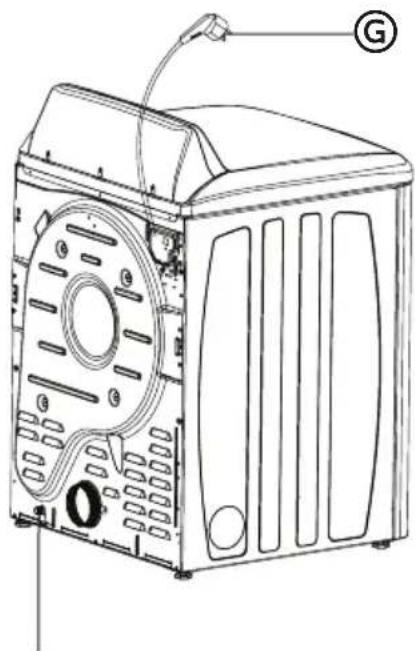
PARTS AND FEATURES
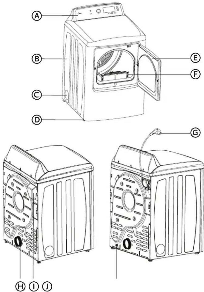
Electric Dryer
Ⓐ Control Panel
B Dryer Cabinet
© Left Venting Hole (for Option)
(D) Leveling Feet
E Dryer Door
Gas Dryer
(F) Lint Screen
© Power Cord (For gas dryer only)
H Exhaust Outlet
① Wiring Box (electric dryer only)
J Gas Inlet Pipe
WARNING
Risk of Fire
Clothes dryer installation must be performed by a qualified installer.
Install the clothes dryer according to the manufacturer's instructions and local codes.
Do not install a clothes dryer with flexible plastic venting materials. If flexible metal (foil type) duct is installed, it must be of a specific type identified by the appliance manufacturer as suitable for use with clothes dryers. Flexible venting materials are known to collapse, be easily crushed, and trap lint. These conditions will obstruct clothes dryer airflow and increase the risk of fire.
To reduce the risk of severe injury or death, follow all installation instructions.
IMPORTANT: When discarding or storing your old clothes dryer, remove the door.
WARNING
Suffocation Hazard
Before you throw away your old appliance, remove the door or lid so that children cannot hide or get trapped inside your old appliance.
Failure to follow these instructions can result in death or brain damage.
IMPORTANT: The dryer, when installed, must be electrically grounded in accordance with local codes, or in the absence of local codes, with the National Electrical Code, ANSI/NFPA 70, or the Canadian Electrical Code, CSA C22.1.
TOOLS NEEDED
• Phillips Screwdriver
- Flat-Blade Screwdriver
• Channel-Lock Adjustable Pliers
- 1/2" Open-End Wrench
- Carpenter'sLevel
• Measuring Tape (12 ft [3.7 m] min.)
- Duct Tape
- Cutting Knife
For gas installations only:
- Pipe Wrench
• 2 Adjustable Wrenches
ADDITIONAL PARTS REQUIRED
• 4" (10.2 cm) Rigid or Flexible Metal Exhaust Ducting
- Vent Clamps
- Duct Tape
• Power Cord (US Electric Dryer Only)
- A power supply cord kit must be purchased to meet local electrical codes. The dryer must use a 3 or 4-wire NEMA 14-30 or 10-30 type SRDT or ST (as required) power supply cord rated at 120/240 volt AC minimum, 30 amp, with 10 AWG conductors terminated with upturned ends or closed loop connectors and marked for use with clothes dryers.
- UL Listed Strain Relief
• Gas Hookup Parts (Gas Dryer Only)
- ^3/_8 " NPT Elbow
- 3/8 "NPT Flare Adapter Fitting
- 3 / 8 " Flexible Gas Connector
- Pipe-Joint Compound
- Mobile Home Installation Kit (Gas Dryer for Mobile Home Only)
LOCATION REQUIREMENTS
WARNING
Do not install the dryer where gasoline or other flammables are kept or stored. If the dryer is installed in a garage, it must be a minimum of 18 inches (45.7 cm) above the floor. Failure to do so can result in death, explosion, fire or burns.
- The dryer must be installed on a solid floor. A concrete floor is the best.
- The floor should be level with maximum slope of 1" (2.5 cm) under entire dryer.
- A suitable location is protected from direct sunlight and heat sources such as radiators, baseboard heaters, or cooking appliances.
- Do not install on carpeting.
- The location must have the appropriate electrical and gas supply outlets. See "Electrical & Gas Supply Requirements" section for details.
- Do not install the dryer in an area where the dryer will come into contact with curtains, thick carpet, or anything that might obstruct the flow of combustion and ventilation air.
- Do not install or store this appliance where it will be exposed to water and/or to the weather.
DRYER DIMENSIONS
ALCOVE OR CLOSET REQUIREMENTS
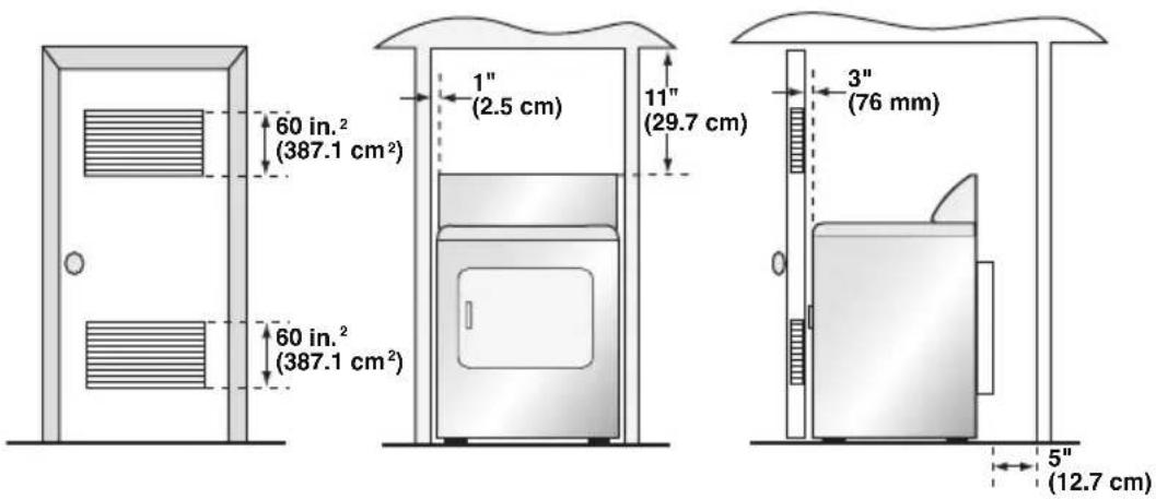
MINIMUM CLEARANCES
- Dimensions shown are the recommended minimum clearance allowances.
• Space on the sides of the dryer is required to avoid noise transfer. - Space 5" (12.7 cm) at the rear of the dryer is necessary to accommodate exhaust ducting.
OTHER REQUIREMENTS
• This dryer must be vented to the outdoors.
- Do not install the dryer in a closet with a solid door.
- A closet door must be louvered or vented with a combined minimum of 72 sq. in. (465 sq. cm.) with a minimum clearance of 3" (76 mm) at the top and bottom. The airflow must not be obstructed in any way.
- No other fuel-burning appliance shall be installed in the same closet as the gas dryer.
ELECTRICAL & GAS SUPPLY REQUIREMENTS
GROUNDING INSTRUCTIONS:
This appliance must be grounded. In the event of malfunction or breakdown, grounding will reduce the risk of electric shock by providing a path of least resistance for electric current. This appliance is equipped with a cord having an equipment-grounding conductor and a grounding plug. The plug must be plugged into an appropriate outlet that is properly installed and grounded in accordance with all local codes and ordinances.
WARNING
Improper connection of the equipment grounding conductor can result in a risk of electric shock. Check with a qualified electrician or service representative or personnel if in doubt as to whether the appliance is properly grounded.
ELECTRIC DRYER (U.S. ONLY)
WARNING
Improper connection of the equipment-grounding conductor can result in a risk of electric shock. Check with a qualified electrician or serviceman if you are in doubt as to whether the appliance is properly grounded.
NOTE: The electrical supply for the dryer must conform with local codes and ordinances and the latest edition of the National Electrical Code, ANSI/NFPA 70.
- If the electrical supply available in the intended dryer location does not meet the above requirements, contact a licensed electrician.
- A dryer operating on a 208 volt power supply will have longer drying times than if it were operating on a 240 volt power supply.
- The dryer is not equipped with a power cord. A kit that meets local electrical codes must be purchased separately. The dryer can be fitted with a 3 or 4-wire NEMA 14-30 or 10-30 type SRDT or ST (as required) power cord rated at 120/240 volt AC minimum, 30 amp, with 3 open-end spade lug connectors with upturned ends or closed loop connectors and marked for use with clothes dryers.
- A UL listed strain relief must be attached to the dryer to hold the power cord.
- Do not use an aluminum wire receptacle with copper-wired power cord and plug (or vice versa). The proper wiring and receptacle is a copper-wired power cord with a copper-wired receptacle.
- The electrical outlet should be located so that the power cord is accessible when the dryer is in the installed position.
WARNING
The dryer must be plugged into a properly grounded 4-wire, single phase, 120/240 volt, 60Hz, AC-only electrical outlet connected to an individual 30-amp circuit, fused with a 30-amp time-delay fuse or circuit breaker. Do not operate a washer and dryer on the same circuit.
NOTE: The electrical service to the dryer must conform with local codes and ordinances and the latest edition of the CSA C22.1 Canadian Electrical Code Part 1.
- If the electrical supply available in the intended dryer location does not meet the above requirements, contact a licensed electrician.
- All Canadian models are shipped with the power cord attached. The power cord should be plugged into a 30-ampere receptacle. In Canada, you may not convert a dryer to 208 volts.
- The electrical outlet should be located so that the power cord is accessible when the dryer is in the installed position.
GAS DRYER
ELECTRICAL SUPPLY REQUIREMENTS
WARNING
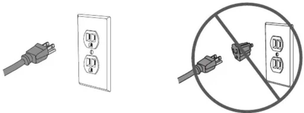
The gas dryer must be plugged into a properly grounded 3-wire, single phase, 120 volt, 60Hz, AC-only electrical outlet, fused with a 15-amp time-delay fuse or circuit breaker.
- The dryer is equipped with a power cord that has a 3 prong plug. Do not cut or remove the grounding prong from the power cord.
- The power cord must be plugged into a mating, 3 prong outlet, grounded in accordance with local codes and ordinances. If a mating outlet is not available, contacted a licensed electrician to have one installed.
- If you are not sure if your outlet is properly grounded, contact a licensed electrician.
- Do not use a 3 prong plug adapter.
- Do not use an extension cord.
GAS SUPPLY REQUIREMENTS
NOTE: The gas service to the dryer must conform with local codes and ordinances and the latest edition of the National Fuel Gas Code, ANSI Z223.1 or in Canada, CAN/CGA B149.1.
Natural Gas
- The dryer is equipped for use with Natural gas.
LP (Liquid Propane) Gas
- The dryer can be converted for use with LP gas.
- Conversion to LP gas must be made by a qualified technician.
Gas Supply Line
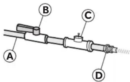
- The gas supply line should be 12 " (1.3 cm) pipe and must have an individual manual shutoff valve installed within 6 ft (183 cm) of the dryer in accordance with the National Fuel Gas Code, ANSI Z223.1/NFPA 54, or in Canada with the Natural Gas and Propane Installation Code, B149.1.
- The shutoff valve should be easy to reach for opening and closing.
- A 18 " NPT minimum plugged tapping, accessible for test gage connection, must be installed immediately upstream of the gas supply connection to the dryer.
- The supply line should terminate with a 3/8 NPT flare adapter fitting.
(A) 12 " NPT Gas Supply Line
B Gas Shutoff Valve
© 18 " NPT Minimum Plugged Tapping
(D) 38 " NPT Flare Adapter Fitting
GAS SUPPLY CONNECTION REQUIREMENTS
This dryer must be connected to the gas supply line with a listed flexible gas connector that complies with the standard for connectors for gas appliances, ANSI Z21.24 or CSA 6.10.
Flexible stainless steel gas connector:
- If local codes permit, use a new flexible stainless steel gas connector (Design Certified by the American Gas Association or CSA International) to connect your dryer to the rigid gas supply line. Use an elbow and a 3/8 flare x 3/8 NPT adapter fitting between the stainless steel gas connector and the dryer gas pipe, as needed to prevent kinking.
BURNER INPUT REQUIREMENTS
Elevations up to 10,000 ft. (3,048 m):
- The design of this dryer is certified by CSA International for use at altitudes up to 10,000 ft. (3,048 m), above sea level at the B.T.U. rating indicated on the model/serial number plate. Burner input adjustments are not required when the dryer is operated up to this elevation.
Elevations above 10,000 ft. (3,048 m):
- When installed above 10,000 ft. (3,048 m) a 4% reduction of the burner B.T.U. rating shown on the model/serial number plate is required for each 1,000 ft. (305 m) increase in elevation.
Gas supply pressure testing:
- The dryer must be disconnected from the gas supply piping system during pressure testing at pressures greater than 1/2 psi (3.5kPa).
EXHAUST SYSTEM REQUIREMENTS
WARNING
This section describes the requirements for a safe and efficient exhaust system. Failure to follow these instructions can result in poor dryer performance, damage to the dryer, and a fire hazard.
IMPORTANT: The dryer must be exhausted to the outdoors.
- The dryer shall not be exhausted into any gas vent, chimney, wall, ceiling, attic, crawl space, or concealed space of a building.
DUCTING
- If your current exhaust system is constructed of plastic or metal foil flexible ducting, replace it with rigid metal ducting.
- Use only 4" (10.2 cm) diameter rigid metal ducting.
- When making turns in the ductwork, use 45^ elbows rather than 90^ elbows. This provides better airflow and can reduce the accumulation of lint in the exhaust system.
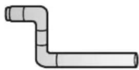
90° - Good
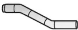
45° - Better
- Do not exceed the length of duct pipe for the number of elbows shown in the chart below. Doing so can cause an accumulation of lint, an increase in drying time, and the creation of a fire hazard.
- Two 45^ elbows equal one 90^ elbow.
| Recommended Maximum Exhaust Length | ||
| Exhaust Hood Types | ||
| Recommended Use Only For Short Run Installations | ||
 |  | |
| No. of 90° Elbows Rigid | Metal Rigid Metal | |
| 0 | 90 feet | 60 feet |
| 1 | 60 feet | 45 feet |
| 2 | 45 feet | 35 feet |
| 3 | 35 feet | 25 feet |
- All joints should be tight to avoid air leaks. The male end of each section of ducting must point away from the dryer.
- Use clamps or duct tape to connect and seal all joints. Do not connect with screws or other fasteners that extend into the interior of the duct as they will create a collection point for lint.
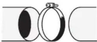
natural_image
Pure diagram of three circular objects with no text or symbolsClamp
- Avoid running the exhaust system through an unheated area as this will cause condensation to form inside the duct and increase the rate of lint accumulation.
- Avoid running the exhaust system vertically through a roof as this may expose the exhaust system to down drafts, causing an increase in air restriction.
- Avoid sagging, compression or crimping of the exhaust system as this will result in reduced airflow and poor dryer performance.
- Do not screen the end of the exhaust system. Lint will accumulate and eventually clog the screen. Use an approved exhaust hood to terminate the duct outdoors.
- The total length of flexible metal duct shall not exceed 2.4 m (7.8 ft).
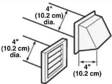
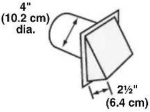
EXHAUST HOOD
- Use an approved exhaust hood with a swing-out damper that opens when the dryer is in operation. When the dryer stops, the damper automatically closes to prevent drafts and the entrance of insects and rodents.
- Louvered or box hood styles are recommended. Angled hood styles are acceptable, but should be used only for short run installations. See the "Recommended Maximum Exhaust Length" chart for more information.
- To avoid restricting airflow, maintain a minimum of 12" (30.5 cm) clearance between the vent hood and the ground or any other obstruction.
MOBILE HOME - ADDITIONAL REQUIREMENTS
- The installation must conform to current Manufactured Home Construction and Safety Standard, Title 24 CFR-Part 3280 or the Canadian Manufactured Home Standard CAN/CSA-Z240 MH.
- Special provisions must be made for outside makeup air. The opening should be at least twice as large as the dryer exhaust outlet.
- If the dryer is exhausted through the floor and into an enclosed area beneath the mobile home, the exhaust system must terminate outside the enclosure with the termination securely fastened to the mobile home structure.
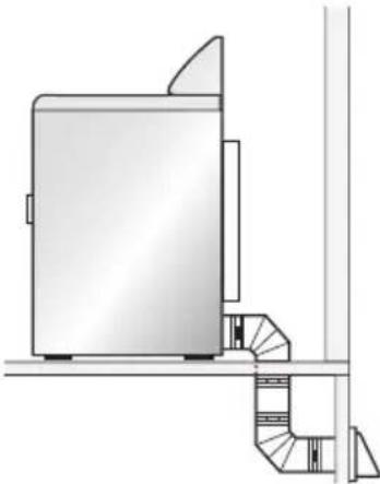
natural_image
Technical line drawing of a cabinet or enclosure with a staircase and ventilation duct (no text or symbols)- The dryer must be fastened to the floor using a mobile home installation kit. Follow the instructions supplied with the kit.
natural_image
Technical diagram showing a mechanical component with a threaded bolt and an arrow indicating direction (no text or symbols)STEP BY STEP INSTRUCTIONS
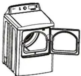
INSTALLING YOUR DRYER
We recommend that your new dryer be installed by a qualified appliance technician. If you feel that you have the skills to install the dryer, please read the installation instructions thoroughly before installing.
CAUTION: If, after completing these steps, you are unsure that the dryer is properly installed, contact a qualified appliance technician.
- Remove all packing materials. This includes the foam base and all adhesive tape holding the dryer accessories inside and outside.
- Inspect and remove any remains of packing, tape or printed materials before using the dryer.
WARNING
To avoid danger of suffocation, keep plastic bag and other packing material away from babies and children. Do not use this bag in cribs, carriages and playpens. The plastic bag could block nose and mouth and prevent breathing. This bag is not a toy.
STEP 2 - ATTACH A POWER CORD TO THE DRYER (ELECTRIC DRYER - U.S. ONLY)
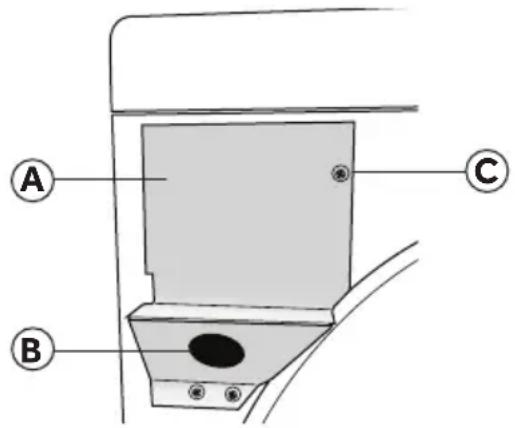
- Remove the screw securing the terminal block access cover, located on the back of the dryer's upper corner.
(A) Terminal Block Access Cover
B Hole in Strain Relief Mounting Bracket
© Access Cover Screw
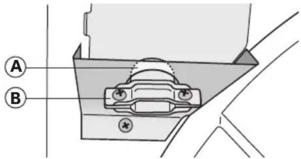
- Insert a UL listed strain relief into the mounting bracket hole. Position the strain relief so that one tab is pointing up and one tab is pointing down. Tighten the strain relief screws just enough to hold the two halves together.
A
Tab
B
Strain Relief
-
Insert a power cord into the strain relief. Take care to ensure that the wire insulation of the power cord is inside the strain relief.
-
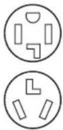
Connect power cord wires following Part A for a 4-wire power cord connection or Part B for a 3-wire power cord connection.
4-wire (recommended) if your home has a 4-wire receptacle (NEMA 14-30 type SRDT or ST):
3-wire (if 4-wire is not available) if your home has a 3-wire receptacle (NEMA 10-30 type SRDT):
CAUTION: A 4-conductor cord shall be used when the appliance is installed in a location where grounding through the neutral conductor is prohibited. Grounding through the neutral conductor is prohibited for (1) new branch-circuit installations, (2) mobile homes, (3) recreational vehicles, and (4) areas where local codes prohibit grounding through the neutral conductors.
- Reinstall the terminal block cover.
- Be sure that none of the wires are touching the dryer drum inside the dryer cabinet.
- Tighten strain relief screws.
PART A - 4-WIRE POWER CORD
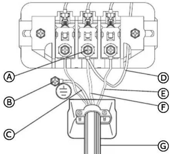
(A) Terminal Block Screw
⑧ Ground Screw (Green)
© Power Cord Ground Wire (Green)
(D) Neutral-Ground Jumper Wire (White)
E Power Cord Line Wires (One Red; One Black)
(F) Power Cord Neutral Wire (White) (G) Power Cord
A1. Attach the power cord ground wire (green) to the cabinet with the green ground screw. Tighten the screw securely.
A2. Attach the power cord neutral wire (white) and the neutral ground jumper wire (white) with the center terminal block screw. Tighten the screw securely.
A3. Attach the remaining 2 power cord line wires (red and black) with the outer terminal block screws. Attach one wire to each terminal block as shown. Tighten both screws securely.
IMPORTANT: Do not make a sharp bend or crimp the wires at connections.
PART B - 3-WIRE POWER CORD
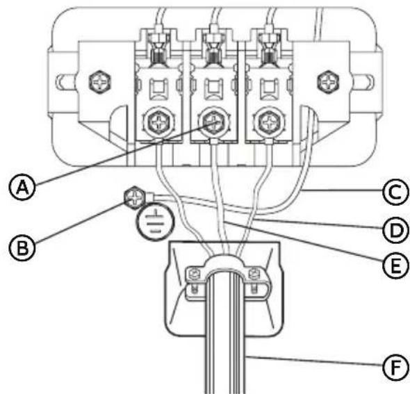
(A) Terminal Block Screw
B Ground Screw (Green)
© Neutral-Ground Jumper Wire (White)
Power Cord Line Wires (One Red; One Black)
E Power Cord Neutral Wire (White)
(F) Power Cord
B1. Attach the power cord neutral wire (white) to the center terminal block screw. Tighten the screw securely.
B2. Attach the remaining 2 power cord line wires (red and black) with the outer terminal block screws. Attach one wire to each terminal block as shown. Tighten both screws securely.
B3. Attach the neutral ground jumper wire (white) to the cabinet with the green ground screw. Tighten the screw securely.
IMPORTANT: Do not make a sharp bend or crimp the wires at connections.
STEP 2 - CONNECT TO A GAS SUPPLY LINE (GAS DRYER ONLY)
NOTE: Do not connect the dryer to an LP gas line without first converting the dryer with a conversion kit. An LP conversion kit must be installed by a qualified technician.
NOTE: Apply a pipe-joint compound that that is resistant to the action of LP gas to all males threads. Do not use plumber's tape.
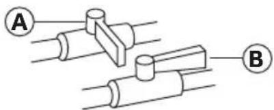
- Turn the gas supply off by moving the shutoff valve to the closed position.
A
Closed Valve
B
Open Valve
-
Disconnect and discard old flexible gas connector. Replace with a new CSA(AGA) approved flexible gas connector.
-
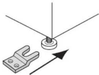
Remove the shipping cap from the gas inlet pipe at the rear of the dryer.
-
Connect a 38 " NPT elbow to the gas inlet pipe on the dryer. Then connect a flare adapter to the elbow.
IMPORTANT: Use a pipe wrench to keep the dryer gas inlet pipe from twisting.
A
Gas Inlet Pipe on
the Dryer
B
^3/_8 " NPT Elbow
©
^3/_8 " NPT Flare Adapter
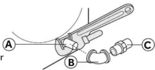
- Connect the dryer to the gas supply line with a flexible gas connector.
A
Flexible Gas Connector
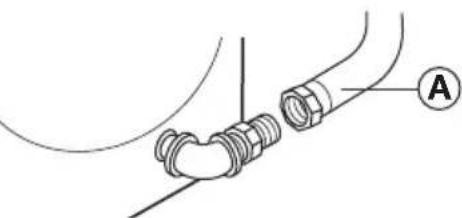
natural_image
Diagram of a mechanical assembly with threaded components and a labeled point A (no text or symbols present)- Tighten the flexible gas connector using two adjustable wrenches.
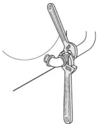
natural_image
Line drawing of a mechanical clamp or wrench tool (no text or symbols present)- Turn the gas supply on by moving the shutoff valve to the open position. The valve is open when the handle is parallel to the gas pipe.
- Check all connections for leaks by applying a noncorrosive leak-detection solution. Bubbles will identify leaks. If leaks are found, close the shutoff valve, retighten the joint, open the shutoff valve, and check again.
WARNING
Never use an open flame to test for gas leaks.
STEP 3 - CONNECT TO AN EXHAUST SYSTEM
WARNING
To reduce the risk of fire, this dryer must be exhausted outdoors.
- Make sure that the exhaust system is free and clear of old lint accumulation prior to connecting the dryer.
- Use 4" (102 mm) rigid or flexible metal ducting to connect the dryer exhaust outlet to the exhaust system.
- Use clamps to seal and secure all joints. Exhaust ducting must not be connected with screws or other fastening devices which extend into the interior of the duct.
NOTES:
- Do not use plastic or metal foil flexible ducting. Excessive lint can build up inside the ductwork, restrict airflow, and create a fire hazard. Restricted airflow will increase drying time.
- The dryer shall not be exhausted into a chimney, a wall, a ceiling, an attic, a crawl space, or a concealed space of a building.
- The dryer must be exhausted to the outdoors. If the dryer is not exhausted outdoors, some fine lint will be expelled into the laundry area. An accumulation of lint in any area of the home can create a health and fire hazard.
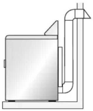
natural_image
Simple line drawing of a portable industrial machine with pipes and a central container (no text or symbols)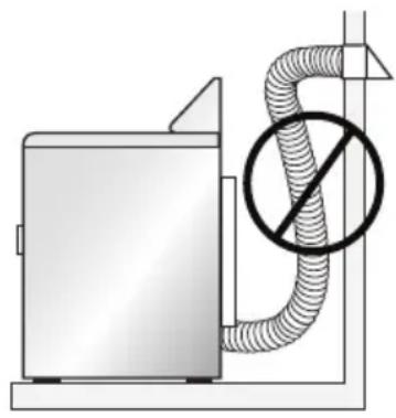
natural_image
Diagram of a utility outlet with a hose and no-smoking symbol (no text or labels)- Place the dryer in its final location. Take care not to crush or kink the exhaust vent. Make sure that all four feet are firmly in contact with the floor and that the dryer rests solidly in position.
NOTE: For a gas dryer, make sure that there are no kinks in the flexible gas line. - Using a carpenter's level, check that the dryer is level from side to side and from front to back.
- If the dryer is not level, adjust the leveling feet. Turn clockwise to extend (raise the dryer) or counterclockwise to retract (lower the dryer).
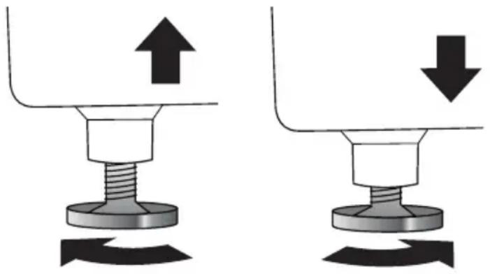
natural_image
Two mechanical diagrams showing a bolt and nut assembly with upward and downward arrows indicating motion (no text or symbols)STEP 5 - COMPLETE THE INSTALLATION
- Plug the dryer power cord into an appropriate outlet.
- Resume power to the outlet. Check that the circuit breaker is switched on.
- Dispose of/recycle all packaging materials.
- Make sure the dryer area is clean and free from combustible materials, gasoline, and other flammable vapors. Also see that nothing (such as boxes, clothing, etc.) obstructs the flow of combustion and ventilation air through the louvered panel located on the rear of the dryer.
- Test dryer operation by selecting a Timed Dry heated cycle. See the "Operating Instructions" section.
NOTE: On gas dryers, before the burner will light, it is necessary for the gas line to be bled of air. If the burner does not light within 45 seconds, the first time the dryer is turned on, the safety switch will shut off the burner. If this happens, turn the dryer to "OFF" and wait 5 minutes before making another attempt to light the burner.
STEP 6 - DOOR REVERSAL (OPTIONAL)
Your dryer door is built to open from (left to right). Use the following instructions to reverse the direction of the door swing so that it opens from (right to left).
NOTE: Different screw types are used for the door and cabinet. The flat-head screws are used for the door hinges.
- Unplug the power cord.
- Remove the four screws attaching each hinge to the door and cabinet.
natural_image
Line drawing of a washing machine with two doors open, showing internal blades (no text or symbols)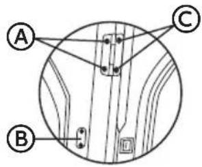
A
Cabinet Screws
B
Locker Cover
©
Door Screws
NOTE: Be sure to support the dryer door when removing the screws.
-
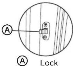
Set the dryer door aside. Remove the screws for the lock cover on the right-hand side of the dryer cabinet, and remove the screws for the lock on the left-hand side of the dryer cabinet.
-
Move the lock to the right-hand side of the cabinet, and move the lock cover onto the left-hand side of the cabinet, and then reinstall both with the screws removed earlier.
-
Remove the screws attaching the inner door board to the outer door board.
-
Remove the inner door board from the outer door board.
-
Turn the inner door board 180°, and then replace the inner door board inside the outer door board.
-
Using the screws removed in Step 5, fasten the inner door board to the outer door board.
-
With the screws removed in Step 2, attach the dryer door to the dryer cabinet.
-
With the handle on the right hand side, fasten the dryer door to the hinges.
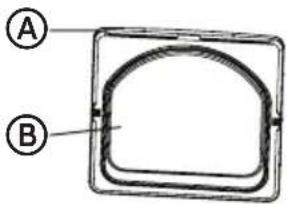
Ⓐ Outside Door Board
B Inner Door Board
CONTROL PANEL AND FEATURES
CONTROL PANEL
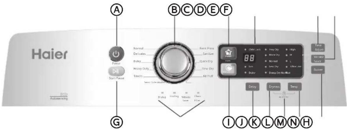
Ⓐ POWER BUTTON
Press once to turn your dryer on. Press again to turn your dryer off. If the dryer is left on for more than 10 minutes without any buttons being pressed, the unit will automatically turn OFF.
B CYCLE SELECTOR
Select your desired cycle for the type of load. The cycle you select determines the heat control for the cycle. The Normal, Delicates, Bulky, Heavy duty, Towels, Casual and Sanitize cycles are Sensor Dry cycles. The Quick Dry, Time Dry and Air fluff cycles are Manual Dry cycles.
© FAVORITE
Press and hold for 3 seconds to remember your favorite drying cycle. Press once to load your favorite cycle setting.
D DIGITAL DISPLAY
The LED digital display will show your remaining time for cycle selected. The LED will show selected delay time when setting the delay time..
E TIME ADJUST BUTTON
This button is effective only for Manual cycles. Push this button to change the drying time you prefer. Push one by one to get your desired the setting time.
F WRINKLE SAVER
Press once to add the Wrinkle Prevent step into the operating program. Press again to cancel selection.
G START/PAUSE BUTTON
Press once to start the program. Press again to pause the program. You can't change any setting except add a garment. Press once again to restart the program.
H CYCLE STATUS LIGHTS
The relative light will be lit when the dryer is in its drying program, say the cooling LED will lit when the dryer is operating in cooling down process. When the whole program is finished, the Clean Filter light will flash to remind you to clean the filter.
① ENERGY SAVER
Press once to select this function so that you can save money with similar drying performance..
J DELAY BUTTON
Delay the start of any cycle for up to 24 hours in one-hour increments. Displayed hours indicates the time the dry will start operation.
Press the button to select the dryness level. Different dryness level will result in different drying time. For clothes to be ironed manually, a lower dryness level should be selected.
L CHILD LOCK
Press the Dryness and Temp buttons together to activate the Child lock function. Press again for another 3 seconds to deactivate the function. All selection except the "Power" will be out of function.
M TEMP BUTTON
Press the button to select the drying temperature.
High - For sturdy cottons or those labeled Tumble Dry.
Medium - For permanent press, synthetics, lightweight cottons, or items labeled Tumble Dry Medium.
Low - For lower heat than Medium to dry synthetic or washable knit fabrics.
Ultra Low - For heat sensitive items labeled Tumble Dry Low or Tumble Dry Warm.
No Heat - Provides just the air cycle without any heat.
N BUZZER BUTTON
Press once to stop the buzzer sound. Press again to activate the sound. Your selection will be kept until next pressing.
CYCLE GUIDE
NOTE: To protect your garments, all options and settings are not available for all cycles. The shaded boxes indicate the default settings for each cycle.
| CYCLE FABRIC TYPE | EST. TIME | DRY TEMP | DRY LEVEL | OPTIONS | |
| Sanitize | Towels, bedding, children's clothing | 60 High | Very Dry | Delay, Wrinkle Saver, Favorite | |
| Heavy Duty | Heavyweight items such as towels and jeans | 55 (Gas) 60 (Electric) | High More Dry | Eco, Delay, Wrinkle Saver, Favorite | |
| Medium Low Ultra Low No Heat | Very Dry Normal Less Dry Damp Dry | ||||
| Normal | Cottons, linens, and mixed garments | 57 (Gas) 63 (Electric) | High More Dry | Eco, Delay, Wrinkle Saver, Favorite | |
| Medium Low Ultra Low No Heat | Very Dry Normal Less Dry Damp Dry | ||||
| Bulky | Blankets, sheets, comforters | 55 (Gas) 60 (Electric) | Medium More Dry | Eco, Delay, Wrinkle Saver, Favorite | |
| High Low Ultra Low No Heat | Very Dry Normal Less Dry Damp Dry | ||||
| Towels | Heavyweight items such as towels and jeans | 58 (Gas) 64 (Electric) | High More Dry | Eco, Delay, Wrinkle Saver, Favorite | |
| Medium Low Ultra Low No Heat | Very Dry Normal Less Dry Damp Dry | ||||
| Perm Press | Cotton poly blends, wrinkle-free shirts and pants | 27 | Medium Normal | Eco, Delay, Wrinkle Saver, Favorite | |
| Low Ultra Low No Heat | Very Dry, More Dry Less Dry Damp Dry | ||||
| Delicates | Lingerie, blouses, and synthetics | 32 | Low Less Dry | Eco, Delay, Wrinkle Saver, Favorite | |
| Ultra Low No Heat | Very Dry More Dry Normal Damp Dry | ||||
| Timed Dry | Cottons, linens, and mixed garments | 40 | High | N/A | Delay, Wrinkle Saver, Favorite, Time Adjust |
| Medium Low Extra Low No Heat | |||||
| Quick Dry | Small loads and sportswear | 30 | High | N/A | Delay, Wrinkle Saver, Favorite, Time Adjust |
| Medium Low Ultra Low No Heat | |||||
| Air Fluff | Rubber, plastic, and heat-sensitive fabrics | 20 | No Heat | N/A | Delay, Wrinkle Saver, Favorite, Time Adjust |
FEATURES
HUMIDITY DRYNESS SENSOR
- The humidity sensor enables the dryer to sense the actual moisture content of garments in the load. Automatic Cycles utilize this information along with air temperature readings to complete the dry cycle at the proper time. This intelligent technology saves energy, reduces static, and protects clothing from damage due to over-drying.
- The sensor also provides consistent and accurate drying results and enables you to fine tune the dryer's performance with the Dry Level button.
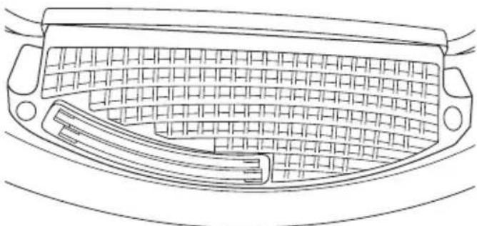
natural_image
Line drawing of a car front panel with mesh grille and handle (no text or symbols)INTERIOR DRUM LIGHT (ON SOME MODELS)
- The interior drum light helps you see inside the dryer and find all of your laundry items. A switch on the cabinet automatically turns the light on when the door is opened and off when the door is closed.
WARNING
To reduce the risk of fire, electric shock, or injury to persons, read the IMPORTANT SAFETY INSTRUCTIONS before operating this appliance.
STEP 1 - PREPARE AND SORT LAUNDRY
- Check garment labels for manufacturers' drying instructions.
- Where possible, turn pockets inside out for uniform drying.
- Tie strings and sashes so they don't tangle.
- Close zippers, snaps and hooks to avoid snagging.
- Make sure buttons and ornaments on the clothes are high temperature resistant and will not damage drum surface.
- To avoid permanently setting stains or soils, check that all stains and soils have been removed during the wash cycle. If not, wash them again.
- To avoid entanglement and ensure easy removal, small articles should be collected in a mesh bag before loading.
- Separate fabrics that attract lint from fabrics that give off lint. Clothes prone to linting should be turned inside out before being put into the dryer.
STEP 2 - CLEAN THE LINT SCREEN
- Clean the lint screen before each use. The filter can be removed by pulling on the handle of the lint screen located inside the dryer door.
- Use your fingers to roll the accumulated lint off of the lint screen. Do not rinse or wash the lint screen to remove lint.
- Slide the lint screen back into place.
NOTES:
- Do not operate the dryer without having the lint screen in place. Without the screen, tumbling garments could enter the exhaust system and cause damage to the dryer.
- Lint buildup on the screen will restrict airflow and cause longer drying times.
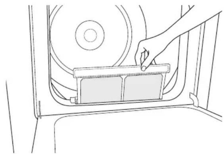
natural_image
Line drawing of a hand placing a rectangular object into a car's seat frame (no text or symbols)STEP 3 - LOAD THE DRYER
- Load damp garments loosely into the dryer drum.
- Close the dryer door.
NOTES:
• Do not pack the dryer full of garments.
- An appropriate load should be 13 to 12 of the drum volume. Allow space for clothes to tumble freely for uniform and wrinkle-free drying.
- When you are drying large bulky items, only 2-3 pieces should be loaded at a time along with a few small and medium-sized garments.
- For delicate clothes or small loads, adding a couple of towels will help to ensure that garments are tumbled. This will produce even drying and reduce wrinkles.
STEP 4 - START THE DRYER
- Turn the dryer on by pressing the POWER BUTTON.
- Select a dry cycle by rotating the CYCLE SELECTION KNOB.
- Modify the default settings and options if desired.
- Press the START/PAUSE BUTTON on the face of the knob to start the dryer.
NOTE:
- Opening the door will pause the operating cycle. Close the door and press the START/PAUSE BUTTON to resume.
WARNING
Always unplug your dryer to avoid electric shock before cleaning.
Ignoring this warning may result in death or injury.
Before using cleaning products, always read and follow manufacturer's instructions and warnings to avoid personal injury or product damage.
CLEANING AND MAINTENANCE
- Only use a damp or sudsy cloth for cleaning the control panel.
- If you spill liquid/powdered softener, bleach or detergent on the cabinet, wipe the cabinet immediately to avoid damage to the finish.
- Do not use abrasive cleansers, harsh chemicals, ammonia, chlorine bleach, concentrated detergent, or solvents to clean the dryer. These chemicals may dissolve, damage, or discolor the dryer.
- Do not use any type of spray cleaner when cleaning the dryer interior. Hazardous fumes or electric shock could occur. If dryer drum becomes stained, clean the drum with a damp cloth. Remove any residue before drying next load.
- Laundry detergent and fabric softener residue can build up on the lint screen. This buildup can cause longer drying times, or cause the dryer to stop before your load is completely dry.
- Wash the lint screen every 6 months, or sooner, if it becomes clogged due to a residue buildup.
Steps to Wash the Lint Screen:
- Remove the normal accumulation of lint with your fingers.
- Wet both sides of lint screen with hot water.
- Apply liquid detergent with water and scrub with a nylon brush.
- Thoroughly rinse the lint screen with hot water.
- Completely dry the lint screen before reinstalling and using the dryer.
REMOVING ACCUMULATED LINT
Inside the Dryer Cabinet
- Lint should be removed every 2 years, or more often, depending on dryer usage. Cleaning should be done by a qualified person.
The Exhaust System
- The exhaust system should be inspected and cleaned at least every 12 months with normal usage. The more the dryer is used, the more often you should check the exhaust system and outdoor exhaust hood for proper operation.
VACATIONING PRECAUTIONS
- Unplug the dryer from the electrical outlet or disconnect the power.
- Washthe lint screen. See the "Washing the Lint Screen" section.
- (For gas dryers only): Close shutoff valve in gas supply line.
MOVING OR STORAGE PREPARATION
In addition to performing the steps in “Vacationing Precautions,” complete the following additional steps.
- Disconnect the dryer from the exhaust system.
- Turn the leveling feet so that they are fully retracted into the dryer cabinet.
• Use masking tape to secure dryer door. - Move and store your dryer in an upright position only.
NOTE: For gas dryers, turn off the gas being supplied to the dryer. Disconnect the dryer from the gas supply line and remove fittings attached to the dryer's gas inlet pipe. Cap the gas supply line.
ERROR CODES
When the dryer senses an error all machine operations will stop, a series of 4 beeps will sound and an error code will be shown in the Estimated Time Remaining display.
| ERROR CODE DESCRIPTION POSSIBLE CAUSE AND SOLUTION | ||
| C9(Short Circuit) | The PCBs failed. Call for service. | |
| E4(Heating Element Problem) | The humidity sensor failed. The unit will complete the current operating cycle.The unit can still operate under the Time cycles.Call for service. | |
| E5 The temperature sensor failed. Call the service center for help. | ||
- The following sounds are normal during the operation of the dryer.
- Tumbling sound: This is normal as the heavy, wet clothes in the dryer are continuously being tossed around.
- Air rushing noise: This happens as the dryer drum spins and the air is rushing through the dryer drum.
- Check that the dryer is plugged in. The plug may have come loose.
- Check that the electrical wall receptacle is of proper voltage. Electric dryers require a 240 volt power supply.
- Check if the circuit breaker needs to be reset, or if the fuse needs to be replaced.
- Check that the dryer door is firmly closed.
- Press the Start/Pause button again if the door is opened during the cycle.
CLOTHES ARE NOT DRYING
- Dryer may be overloaded. Wet clothes should not fill more than 12 of the drum volume.
- Check the exhaust ducting and exhaust hood. The entire exhaust system should be free of obstructions.
- The exhaust system should be maintained, and cleaned regularly.
- Dryer load may need to be sorted. Heavyweight clothes should be separated from lightweight clothes.
- Bulky items may require repositioning.
- Check the lint screen. Lint screen should be cleaned before each load.
- Check that the dryer is not set on the Air Fluff (no heat) temperature setting.
- For gas dryers, check that the gas supply line is open.
Rattling or clanking noises:
- Foreign objects may be in the dryer drum. Stop the dryer and check for foreign objects such as loose change, keys and heavy objects.
Vibration noises:
- Load may be uneven. Stop the dryer and rearrange the load.
- Dryer may not be level. Check that all four leveling feet are resting firmly on the floor and that the dryer is level.
• See the "Normal Operating Sounds" section.
Static:
- Caused by over-drying. Adjust for shorter drying time and use a fabric softener or a dryer sheet.
Loads are wrinkled:
- The load may have been left in the dryer too long at the end of the cycle. Be sure to remove clothes promptly after the load ends.
- Dryer may be overloaded. The dryer drum should be at most half full.
Odors:
- Wet clothes left in the washer and/or dryer may develop an odor. Drying will not remove this odor. Rewash clothes before drying them.
- The electric heating element may have an odor when the dryer is used for the first time. The odor will be gone after the first cycle.
FOR MORE HELP, VISIT HAIER.COM OR CALL THE CONSUMER HELP LINE AT 1-877-377-3639.
LIMITED WARRANTY
IN HOME SERVICE
FULL ONE YEAR WARRANTY
For 12 months from the date of original retail purchase, Haier will repair or replace any part free of charge including labor that fails due to a defect in materials or workmanship.
Haier may replace or repair at their sole discretion any part, sub system including the entire product.
Product must be accessible, without encumbrance and installed properly to receive for warranty repair service.
LIMITED WARRANTY
After one year from the original retail purchase date, Haier will provide a part at no cost, as indicated below, to replace said part as a result of a defect in materials or workmanship. Haier is solely responsible for the cost of the part. All other costs, such as labor, trip charge, etc., are the responsibility of the owner.
Second through Fifth Year
Haier will provide the drum if defective in material or workmanship.
NOTE: This warranty commences on the date the item was purchased, and the original purchase receipt must be presented to the authorized service representative before warranty repairs are rendered.
Exceptions: Commercial Use Warranty
90 days labor from date of original purchase
90 days parts from date of original purchase
No other warranty applies.
FOR WARRANTY SERVICE
All service must be performed by a Haier authorized service center. For the name and telephone number of the nearest authorized service center, please call 1-877-337-3639.
Before calling please have available the following information:
Model number and serial number of your appliance. The name and address of the dealer you purchased the unit from and the date of purchase.
A clear description of the problem.
A proof of purchase (sales receipt).
This warranty covers home appliance services within the contiguous United States and Canada and where available in Alaska, Hawaii and Puerto Rico.
What is not covered by this warranty:
Replacement or repair of household fuses, circuit breakers, wiring or plumbing.
A product whose original serial number has been removed or altered.
Any service charges not specifically identified as normal such as normal service area or hours.
Damage to clothing.
Damage incurred in shipping.
Damage caused by improper installation or maintenance.
Damage from misuse, abuse accident, fire, flood, or acts of nature.
Damage from service other than an authorized Haier dealer or service center.
Damage from incorrect electrical current, voltage or supply.
Damage resulting from any product modification, alteration or adjustment not authorized by Haier.
Adjustment of consumer operated controls as identified in the owner's manual.
Hoses, knobs, lint trays and all attachments, accessories and disposable parts.
Labor, service transportation, and shipping charges for the removal and replacement of defective parts beyond the initial 12-month period.
Damage from other than normal household use.
Any transportation and shipping charges.
THIS LIMITED WARRANTY IS GIVEN IN LIEU OF ALL OTHER WARRANTIES, EXPRESSED OR, INCLUDING THE WARRANTIES OF MERCHANTABILITY AND FITNESS FOR A PARTICULAR PURPOSE
The remedy provided in this warranty is exclusive and is granted in lieu of all other remedies.
This warranty does not cover incidental or consequential damages, so the above limitations may not apply to you. Some states do not allow limitations on how long an implied warranty lasts, so the above limitations may not apply to you.
This warranty gives you specific legal rights, and you may have other rights, which vary, from state to state.
Haier America
Wayne, NJ 07470
TABLE DES MATIÈRES
IMPORTANTES INSTRUCTIONS DE SÉCURITÉ ...... 35
natural_image
Line drawing of a microwave oven with ventilation slots and mounting feet (no text or symbols)(H) I J
natural_image
Line drawing of a washing machine casing with labeled components (no text or symbols beyond basic labels)Sécheuse à gaz
Sécheuse électrique
natural_image
Illustration of three electrical components: a plug, a two-pin electrical outlet, and a crossed-out electrical socket (no text or symbols)SPÉCIFICATIONS DE L'ALIMENTATION EN GAZ
SPÉCIFICATIONS DU RACCORDEMENT DE L'ALIMENTATION EN GAZ
natural_image
Pure diagram of three circular components with no text or symbolsBride
natural_image
Technical diagram showing a mechanical component with a threaded bolt and an arrow indicating direction (no text or symbols)INSTRUCTIONS ÉTAPE PAR ÉTAPE
INSTALLATION DE LA SÉCHEUSE
natural_image
Diagram of a mechanical or electrical component with labeled point A (no text or symbols present)natural_image
Line drawing of a mechanical clamp or tool (no text or symbols present)natural_image
Line drawing of a simple industrial machine with pipes and housing (no text or symbols)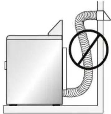
natural_image
Diagram of a utility or gasifier with a hose and nozzled symbol (no text or labels)ÉTAPE 4 – NIVELLEMENT DE LA SÉCHEUSE
natural_image
Two mechanical diagrams showing a bolt and nut assembly with upward and downward arrows indicating motion (no text or symbols)ÉTAPE 5 - FIN DE L'INSTALLATION
natural_image
Line drawing of a washing machine with two doors open, showing internal compartments (no text or symbols)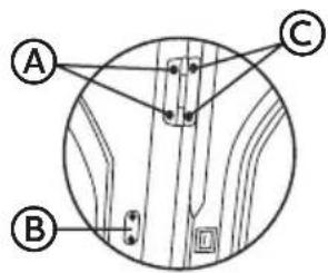
Ⓐ BOUTON POWER (MISE SOUS TENSION)
natural_image
Line drawing of a car front grille with grid pattern and handle (no text or symbols)LAMPE INTERNE DU TAMBOUR (SUR CERTAINS MODÈLES)
natural_image
Line drawing of a hand placing a component into a CD inside a vehicle (no text or symbols)ÉTAPE 3 - CHARGEMENT DE LA SÉCHEUSE
natural_image
Illustration of three electrical components: a wire with plug, two electrical outlets, and a circle showing an open socket (no text or symbols)natural_image
Simple line drawing of three circular objects with a knob, no text or symbols presentAbrazadera
natural_image
Line drawing of a kitchen appliance with stairs and a chimney (no text or symbols)SOLAMENTE PARA LA SECADORA A GAS (SOLAMENTE PARA CASAS RODANTES)
natural_image
Technical diagram showing a mechanical component with a threaded bolt and an arrow indicating direction (no text or symbols)INSTRUCCIONES PASO A PASO
natural_image
Diagram of a cable or wire connection with a labeled component A (no text or symbols present)natural_image
Line drawing of a mechanical clamp or wrench tool (no text or symbols present)natural_image
Technical line drawing of a mechanical device with no visible text or symbols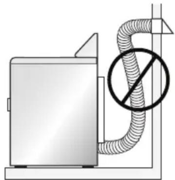
natural_image
Diagram of a utility or gasifier with a hose and no-smoking symbol (no text or labels)PASO 4 - NIVELE LA SECADORA
natural_image
Line drawing of a washing machine with two doors open, showing internal blades (no text or symbols)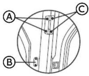
A BOTÓN POWER (ENCENDIDO)
F WRINKLE SAVER (ANTIARRUGAS)
natural_image
Line drawing of a car interior with a grid-patterned grille and handle (no text or symbols)LUZ INTERNA DEL TAMBOR (EN ALGUNOS MODELOS)
natural_image
Line drawing of a hand placing a component into a car's seat panel (no text or symbols)PASO 3 – CARGUE LA SECADORA
If you have a problem with this product, please contact the
"Haier Customer Satisfaction Center" at
1-877-337-3639.
DATED PROOF OF PURCHASE, MODEL #, AND SERIAL #
REQUIRED FOR WARRANTY SERVICE
IMPORTANT
HLTD600AEW, HLTD600ACW
Wayne, NJ 07470
HLTD600AGW
Issued: April 2015 Printed in China Part # 00XXXXXXXXX