MEDB955FW - Tumble drier MAYTAG - Free user manual and instructions
Find the device manual for free MEDB955FW MAYTAG in PDF.

User questions about MEDB955FW MAYTAG
0 question about this device. Answer the ones you know or ask your own.
Ask a new question about this device
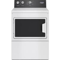
Download the instructions for your Tumble drier in PDF format for free! Find your manual MEDB955FW - MAYTAG and take your electronic device back in hand. On this page are published all the documents necessary for the use of your device. MEDB955FW by MAYTAG.
USER MANUAL MEDB955FW MAYTAG
Tools and Parts....4
LOCATION REQUIREMENTS....5
Installation Clearances....5
Dryer Dimensions....5
ELECTRICAL REQUIREMENTS - U.S.A. ONLY 6
Grounding Instructions....7
ELECTRIC DRYER POWER HOOKUP - CANADA ONLY......7
Electrical Requirements 7
Grounding Instructions....7
GAS DRYER POWER HOOKUP - U.S.A. AND CANADA......8
Electrical Requirements 8
Grounding Instructions....8
Gas Supply Requirements....8
Gas Type....8
Gas Supply Line....8
Gas Supply Connection Requirements 9
Burner Input Requirements....9
Dryer Gas Pipe....9
INSTALL LEVELING LEGS....9
MAKE ELECTRICAL CONNECTION - U.S.A. ONLY 10
Electrical Connection.... 10
Power Supply Cord Connection.... 10
Direct Wire Connection.... 12
MAKE GAS CONNECTION - U.S.A. AND CANADA 16
VENTING....16
Venting Requirements....16
Plan Vent System....17
Install Vent System....18
CONNECT INLET HOSES....18
CONNECT VENT 20
LEVEL DRYER....20
COMPLETE INSTALLATION CHECKLIST 21
REVERSE DOOR SWING....22
REINSTALL HINGES ON DOOR....24
REVERSE STRIKE PLATE 24
Table des matières
SÉCURITÉ DE LA SÉCHEUSE....25
EXIGENCES D'INSTALLATION 27
Date of installation:
Installer:
Model number:
Serial number:
NOTES CONCERNANT L'INSTALLATION
Date d'achat :
Your safety and the safety of others are very important.
We have provided many important safety messages in this manual and on your appliance. Always read and obey all safety messages.

This is the safety alert symbol.
This symbol alerts you to potential hazards that can kill or hurt you and others.
All safety messages will follow the safety alert symbol and either the word "DANGER" or "WARNING."
These words mean:
! DANGER
You can be killed or seriously injured if you don't immediately follow instructions.
WARNING
You can be killed or seriously injured if you don't follow instructions.
All safety messages will tell you what the potential hazard is, tell you how to reduce the chance of injury, and tell you what can happen if the instructions are not followed.

WARNING - "Risk of Fire"
- Clothes dryer installation must be performed by a qualified installer.
- Install the clothes dryer according to the manufacturer's instructions and local codes.
- Do not install a clothes dryer with flexible plastic venting materials or flexible metal (foil type) duct. If flexible metal duct is installed, it must be of a specific type identified by the appliance manufacturer as suitable for use with clothes dryers. Flexible venting materials are known to collapse, be easily crushed, and trap lint. These conditions will obstruct clothes dryer airflow and increase the risk of fire.
- To reduce the risk of severe injury or death, follow all installation instructions.
- Save these instructions.
IMPORTANT: When discarding or storing your old clothes dryer, remove the door.

WARNING
Fire Hazard
Failure to follow safety warnings exactly could result in serious injury, death, or property damage.
Do not install a booster fan in the exhaust duct.
Install all clothes dryers in accordance with the installation instructions of the manufacturer of the dryer.
WARNING: For your safety, the information in this manual must be followed to minimize the risk of fire or explosion, or to prevent property damage, personal injury, or death.
- Do not store or use gasoline or other flammable vapors and liquids in the vicinity of this or any other appliance.
-
WHAT TO DO IF YOU SMELL GAS:
-
Do not try to light any appliance.
- Do not touch any electrical switch; do not use any phone in your building.
- Clear the room, building, or area of all occupants.
- Immediately call your gas supplier from a neighbor's phone. Follow the gas supplier's instructions.
- If you cannot reach your gas supplier, call the fire department.
- Installation and service must be performed by a qualified installer, service agency, or the gas supplier.
WARNING: Gas leaks cannot always be detected by smell.
Gas suppliers recommend that you use a gas detector approved by UL or CSA.
For more information, contact your gas supplier.
If a gas leak is detected, follow the "What to do if you smell gas" instructions.
IMPORTANT: The gas installation must conform with local codes, or in the absence of local codes, with the National Fuel Gas Code, ANSI Z223.1/NFPA 54 or the Canadian Natural Gas and Propane Installation Code, CSA B149.1.
The dryer must be electrically grounded in accordance with local codes, or in the absence of local codes, with the National Electrical Code, ANSI/NFPA 70 or Canadian Electrical Code, CSA C22.1.
In the State of Massachusetts, the following installation instructions apply:
■ Installations and repairs must be performed by a qualified or licensed contractor, plumber, or gasfitter qualified or licensed by the State of Massachusetts.
■ If using a ball valve, it shall be a T-handle type.
■ A flexible gas connector, when used, must not exceed 3 feet.
INSTALLATION REQUIREMENTS
TOOLS AND PARTS
Gather the required tools and parts before starting installation. Read and follow the instructions provided with any tools listed here.
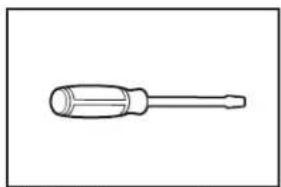
Tools needed for all installations:
natural_image
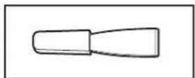
Line drawing of a screwdriver with a flat head and threaded shaft (no text or symbols)Flat-blade screwdriver
natural_image
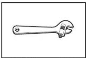
Line drawing of an adjustable wrench (no text or symbols)Adjustable wrench that opens to 1" (25 mm) or hex-head socket wrench
natural_image
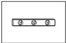
Simple line drawing of a rectangular object with three circular holes, no text or symbols present.Level
natural_image
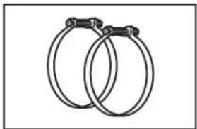
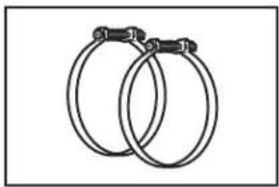
Two interlocked rings with metal clips attached (no text or symbols)Vent clamps
natural_image
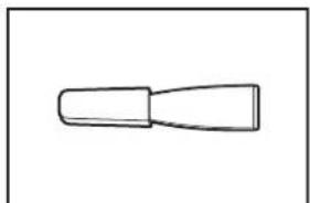
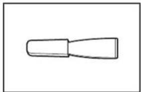
Simple line drawing of a tool or component (no text or symbols)Plastic putty knife
natural_image
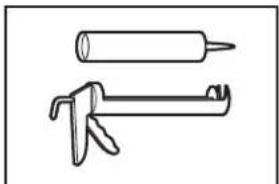
Two hand tools: a cylindrical tool and a saw tool (no text or symbols)Caulking gun and compound (for installing new exhaust vent)
natural_image
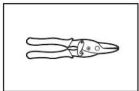
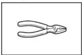
Line drawing of a pair of pliers (no text or symbols)Tin snips (new vent installations)
natural_image
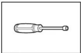
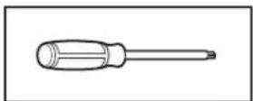
Simple line drawing of a screwdriver with a handle and end cap (no text or symbols)1/4" (6 mm) nut driver (recommended)
natural_image
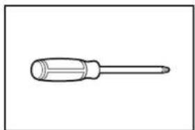
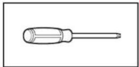
Simple line drawing of a screwdriver (no text or symbols)2 Phillips screwdriver
natural_image
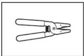
Line drawing of a pair of pliers with no text or symbolsWire stripper (direct wire installations)
natural_image
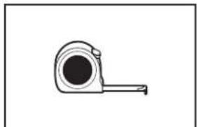
Simple line drawing of a measuring tape (no text or symbols)Tape measure
natural_image
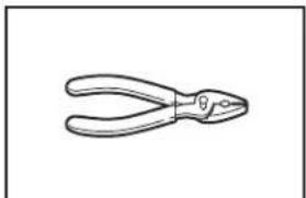
Line drawing of a pair of pliers (no text or symbols)Pliers
Tools needed for gas installations:
natural_image
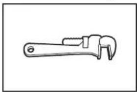
Line drawing of an adjustable wrench (no text or symbols)8" (203 mm) or 10" (254 mm) pipe wrench
natural_image
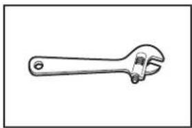
Line drawing of an adjustable wrench (no text or symbols)8" (203 mm) or 10" (254 mm) adjustable wrench (for gas connections)
natural_image
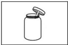
Simple line drawing of a jar with a lid (no text or symbols)Pipe-joint compound resistant to LP gas
Parts supplied (all models):
natural_image
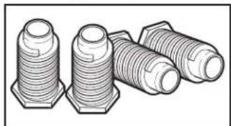
Illustration of three threaded fasteners with hexagonal bases (no text or symbols)Leveling legs (4)
Parts supplied (steam models):
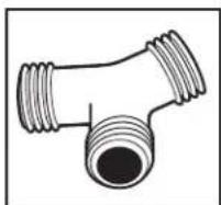
"Y" connector
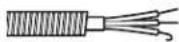
natural_image
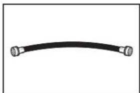
Simple black curved line with two metallic connectors at both ends (no text or symbols)Short inlet hose
Rubber washer (4)
Parts package is located in dryer drum. Check that all parts are included.
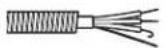
Parts needed (steam models):

natural_image
Coiled black hose with metallic connectors (no text or symbols visible)5' (1.52 m) inlet hose
If using a power supply cord:
Use a UL-listed power supply cord kit marked for use with clothes dryers. The kit should contain:
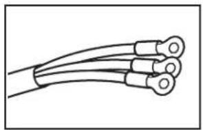
A UL-listed 30-amp power supply cord, rated 120/240 volt minimum, with a temperature rating of 140°F (60°C) minimum. The cord should be type SRD or SRDT and be at least 4 ft. (1.22 m) long. The wires that connect to the dryer must end in ring terminals or spade terminals with upturned ends.
■ A UL-listed strain relief.
Parts needed: (Not supplied with dryer)
Check local codes. Check existing electrical supply and venting. See “Electrical Requirements” and “Venting Requirements” before purchasing parts.
Mobile home installations require metal exhaust system hardware available for purchase from the dealer from whom you purchased your dryer. For further information, please refer to the “Assistance or Service” section in your Use and Care Guide.
LOCATION REQUIREMENTS
WARNING

Explosion Hazard
Keep flammable materials and vapors, such as gasoline, away from dryer.
Place dryer at least 18 inches (460 mm) above the floor for a garage installation.
Failure to do so can result in death, explosion, or fire.
You will need:
■ A location allowing for proper exhaust installation. See "Venting Requirements."
■ A separate 15- or 20-amp circuit needed for gas dryers and 30-amp circuit needed for electric dryers.
If using power supply cord, a grounded electrical outlet located within 2 ft. (610 mm) of either side of dryer. See “Electrical Requirements.”
■ Floor must support dryer weight of 200 lbs. (90.7 kg). Also consider weight of companion appliance.
■ Level floor with maximum slope of 1" (25 mm) under entire dryer. If slope is greater than 1" (25 mm), clothes may not tumble properly and automatic sensor cycles may not operate correctly.
■ For garage installation, place dryer at least 18" (460 mm) above floor.
■ Steam models only: Cold water faucets located within 4 ft. (1.2 m) of the water fill valves, and water pressure of 20–100 psi (137.9–689.6 kPa). You may use the water supply for your washer using the "Y" connector and short hose which are provided.
IMPORTANT: Do not operate, install, or store dryer where it will be exposed to water, weather, or at temperatures below 45^ F ( 7^ C). Lower temperatures may cause dryer not to shut off at end of automatic sensor cycles, resulting in longer drying times.
NOTE: No other fuel-burning appliance can be installed in the same closet as a dryer.
INSTALLATION CLEARANCES
For each arrangement, consider allowing more space for ease of installation and servicing, spacing for companion appliances and clearances for walls, doors, and floor moldings. Space must be large enough to allow door to fully open. Add spacing on all sides of dryer to reduce noise transfer. If a closet door or louvered door is installed, top and bottom air openings in door are required.
Check code requirements. Some codes limit, or do not permit, installation of the dryer in garages, closets, mobile homes, or sleeping quarters. Contact your local building inspector.
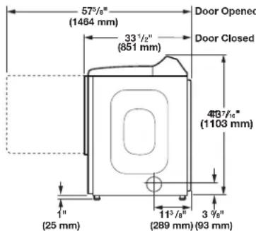
DRYER DIMENSIONS
Front Controls Models
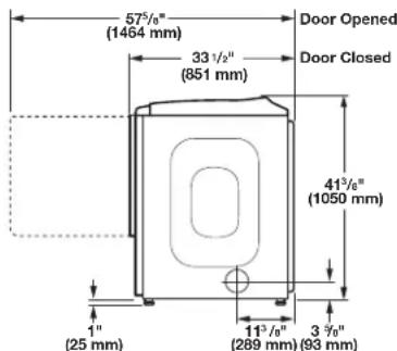
text_image
57½" (1464 mm) 33 ½" (851 mm) Door Opened Door Closed 41¾" (1050 mm) 1" (25 mm) 11¾" (289 mm) 3 ¾" (93 mm)Side view
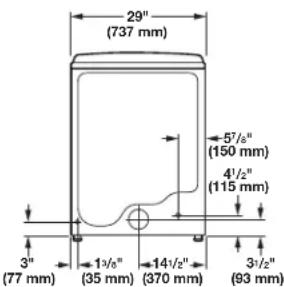
text_image
29" (737 mm) 5"/6" (150 mm) 4"/2" (115 mm) 3" (77 mm) 1"/8" (35 mm) 14"/2" (370 mm) 3"/2" (93 mm)Back view
Bottom view:
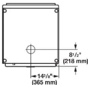
text_image
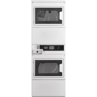
8¹/₂" (218 mm) 14³/8" (365 mm)Rear Controls Models
text_image
57°/8" (1464 mm) 33 1/2" (851 mm) Door Opened Door Closed 4B3 7/8" (1103 mm) 1" (25 mm) 11 3 9/8" (289 mm) (93 mm)
text_image
29" (737 mm) 5½" (150 mm) 4½" (115 mm) 3" (77 mm) 1¾" (35 mm) 14½" (370 mm) 3½" (93 mm)Back viewSide view
Bottom view:

text_image
81/2" (218 mm) 143/8" (365 mm)NOTE: Most installations require a minimum of 6" (152 mm) clearance behind dryer for exhaust vent with elbow. See "Venting Requirements."
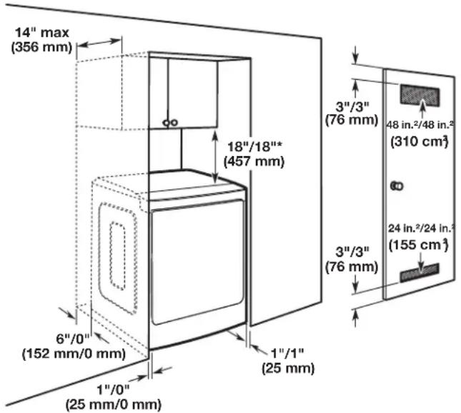
Spacing for recessed area or closet installation
The dimensions shown are for the recommended spacing allowed.
■ Additional spacing should be considered for ease of installation and servicing.
■ Additional clearances might be required for wall, door, and floor moldings.
■ Additional spacing of 1" (25 mm) on all sides of the dryer is recommended to reduce noise transfer.
■ For closet installation with a door, minimum ventilation openings in the top and bottom of the door are required. Louvered doors with equivalent ventilation openings are acceptable.
■ Companion appliance spacing should also be considered.
text_image
14" max (356 mm) 18"/18"* (457 mm) 6"/0" (152 mm/0 mm) 1"/0" (25 mm/0 mm) 1"/1" (25 mm) 3"/3" (76 mm) 3"/3" (76 mm) 48 in.²/48 in.² (310 cm³) 24 in.²/24 in.² (155 cm³)Recommended/Minimum spacing
Mobile home – Additional installation requirements:
This dryer is suitable for mobile home installations. The installation must conform to the Manufactured Home Construction and Safety Standard, Title 24 CFR, Part 3280 (formerly the Federal Standard for Mobile home construction and Safety, Title 24, HUD Part 280) or Standard CAN/CSA-Z240 MH.
Mobile home installations require:
All dryers:
■ Metal exhaust system hardware, available for purchase from your dealer. For further information, see “Assistance or Service” section in your Use and Care Guide.
■ Special provisions must be made in mobile homes to introduce outside air into dryer. Openings (such as a nearby window) should be at least twice as large as dryer exhaust opening.
For gas dryers mobile home installations:
■ Mobile Home Installation Hold-down Kit is available to order. For further information, see "Assistance or Service" section in your Use and Care Guide.
ELECTRICAL REQUIREMENTS - U.S.A. ONLY (SPÉCIFICATIONS ÉLECTRIQUES - ÉTATS-UNIS SEULEMENT)
It is your responsibility:
■ To contact a qualified electrical installer.
To be sure that the electrical connection is adequate and in conformance with the National Electrical Code, ANSI/NFPA 70 – latest edition and all local codes and ordinances.
The National Electrical Code requires a 4-wire power supply connection for homes built after 1996, dryer circuits involved in remodeling after 1996, and all mobile home installations. A copy of the above code standards can be obtained from: National Fire Protection Association, One Batterymarch Park, Quincy, MA 02269.
■ To supply the required 3- or 4-wire, single-phase, 120/240-volt, 60-Hz, AC-only electrical supply (or 3- or 4-wire, 120/208-volt electrical supply, if specified on the serial/rating plate) on a separate 30-amp circuit, fused on both sides of the line. Connect to an individual branch circuit. Do not have a fuse in the neutral or grounding circuit.
■ Do not use an extension cord.
If codes permit and a separate ground wire is used, it is recommended that a qualified electrician determine that the ground path is adequate.
Electrical Connection
To properly install your dryer, you must determine the type of electrical connection you will be using and follow the instructions provided for it here.
This dryer is manufactured ready to install with a 3-wire electrical supply connection. The neutral ground conductor is permanently connected to the neutral conductor (white wire) within the dryer. If the dryer is installed with a 4-wire electrical supply connection, the neutral ground conductor must be removed from the external ground connector (green screw), and secured under the neutral terminal (center or white wire) of the terminal block. When the neutral ground conductor is secured under the neutral terminal (center or white wire) of the terminal block, the dryer cabinet is isolated from the neutral conductor.
If local codes do not permit the connection of a neutral ground wire to the neutral wire, see "Optional 3-wire connection" section.
A 4-wire power supply connection must be used when the appliance is installed in a location where grounding through the neutral conductor is prohibited. Grounding through the neutral is prohibited for (1) new branch-circuit installations, (2) mobile homes, (3) recreational vehicles, and (4) areas where local codes prohibit grounding through the neutral conductors.
If using a power supply cord:
Use a UL-listed power supply cord kit marked for use with clothes dryers. The kit should contain:
■ A UL-listed 30-amp power supply cord, rated 120/240-volt minimum, with a temperature rating of 140°F (60°C) minimum. The cord should be type SRD or SRDT, and be at least 4 ft. (1.22 m) long. The wires that connect to the dryer must end in ring terminals or spade terminals with upturned ends.
■ A UL-listed strain relief.
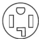
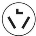
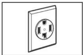
If your outlet looks like this:

4-wire
receptacle
(14-30R)
Then choose a 4-wire power supply cord with ring or spade terminals and UL-listed strain relief. The 4-wire power supply cord, at least 4 ft. (1.22 m) long, must have four 10-gauge solid copper wires and match a 4-wire receptacle of NEMA-Type 14-30 R. The ground wire (ground conductor) may be either green or bare. The neutral conductor must be identified by a white cover.
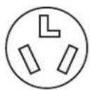
If your outlet looks like this:

3-wire
receptacle
(10-30R)
Then choose a 3-wire power supply cord with ring or spade terminals and UL-listed strain relief. The 3-wire power supply cord, at least 4 ft. (1.22 m) long, must have three 10-gauge solid copper wires and match a 3-wire receptacle of NEMA-Type 10-30R.
If connecting by direct wire:
Power supply cable must match power supply (4-wire or 3-wire) and be:
■ Flexible armored cable or nonmetallic sheathed copper cable (with ground wire), covered with flexible metallic conduit. All current-carrying wires must be insulated.
■ 10-gauge solid copper wire (do not use aluminum) at least 5 ft. (1.52 m) long.
GROUNDING INSTRUCTIONS
■ For a grounded, cord-connected dryer:
This dryer must be grounded. In the event of malfunction or breakdown, grounding will reduce the risk of electric shock by providing a path of least resistance for electric current. This dryer uses a cord having an equipment-grounding conductor and a grounding plug. The plug must be plugged into an appropriate outlet that is properly installed and grounded in accordance with all local codes and ordinances
■ For a permanently connected dryer:
This dryer must be connected to a grounded metal, permanent wiring system, or an equipment-grounding conductor must be run with the circuit conductors and connected to the equipment-grounding terminal or lead on the dryer.
WARNING: Improper connection of the equipment-grounding conductor can result in a risk of electric shock. Check with a qualified electrician or service representative or personnel if you are in doubt as to whether the dryer is properly grounded. Do not modify the plug on the power supply cord: if it will not fit the outlet, have a proper outlet installed by a qualified electrician.
SAVE THESE INSTRUCTIONS
ELECTRIC DRYER POWER HOOKUP - CANADA ONLY
ELECTRICAL REQUIREMENTS
WARNING

Electrical Shock Hazard
Plug into a grounded 4 prong outlet.
Failure to do so can result in death or electrical shock.
It is your responsibility:
■ To contact a qualified electrical installer.
To be sure that the electrical connection is adequate and in conformance with Canadian Electrical Code, C22.1 – latest edition and all local codes. A copy of above codes standard may be obtained from: Canadian Standards Association, 178 Rexdale Blvd., Toronto, ON M9W 1R3 CANADA.
■ To supply the required 4-wire, single-phase, 120/240-volt, 60-Hz, AC-only electrical supply on a separate 30-amp circuit, fused on both sides of the line. A time-delay fuse or circuit breaker is recommended. Connect to an individual branch circuit.
This dryer is equipped with a CSA International Certified Power Cord intended to be plugged into a standard 14-30R wall receptacle. The cord is 5 ft. (1.52 m) long. Be sure wall receptacle is within reach of dryer's final location.
4-wire receptacle
(14-30R)
For further information, please reference service numbers located in "Assistance or Service" section of your Use and Care Guide.
GROUNDING INSTRUCTIONS
■ For a grounded, cord-connected dryer:
This dryer must be grounded. In the event of malfunction or breakdown, grounding will reduce the risk of electric shock by providing a path of least resistance for electric current. This dryer is equipped with a cord having an equipment-grounding conductor and a grounding plug. The plug must be plugged into an appropriate outlet that is properly installed and grounded in accordance with all local codes and ordinances.
WARNING: Improper connection of the equipment-grounding conductor can result in a risk of electric shock. Check with a qualified electrician or service representative or personnel if you are in doubt as to whether the dryer is properly grounded. Do not modify the plug provided with the dryer: if it will not fit the outlet, have a proper outlet installed by a qualified electrician.
SAVE THESE INSTRUCTIONS
GAS DRYER POWER HOOKUP - U.S.A. AND CANADA
ELECTRICAL REQUIREMENTS
WARNING

Electrical Shock Hazard
Plug into a grounded 3 prong outlet.
Do not remove ground prong.
Do not use an adapter.
Do not use an extension cord.
Failure to follow these instructions can result in death, fire, or electrical shock.
■ 120-Volt, 60-Hz, AC-only, 15- or 20-amp fused electrical supply is required. A time-delay fuse or circuit breaker is recommended. It is also recommended that a separate circuit serving only this dryer be provided.
GROUNDING INSTRUCTIONS
■ For a grounded, cord-connected dryer:
This dryer must be grounded. In the event of malfunction or breakdown, grounding will reduce the risk of electric shock by providing a path of least resistance for electric current. This dryer is equipped with a cord having an equipment-grounding conductor and a grounding plug. The plug must be plugged into an appropriate outlet that is properly installed and grounded in accordance with all local codes and ordinances.
WARNING: Improper connection of the equipment-grounding conductor can result in a risk of electric shock. Check with a qualified electrician or service representative or personnel if you are in doubt as to whether the dryer is properly grounded. Do not modify the plug provided with the dryer: if it will not fit the outlet, have a proper outlet installed by a qualified electrician.
SAVE THESE INSTRUCTIONS
GAS SUPPLY REQUIREMENTS
WARNING
Explosion Hazard
Use a new CSA International approved gas supply line.
Install a shut-off valve.
Securely tighten all gas connections.
If connected to LP, have a qualified person make sure gas pressure does not exceed 13" (330 mm) water column.
Examples of a qualified person include:
licensed heating personnel, authorized gas company personnel, and authorized service personnel.
Failure to do so can result in death, explosion, or fire.
GAS TYPE
Natural Gas:
This dryer is equipped for use with Natural gas. It is design-certified by CSA International for LP (propane or butane) gases with appropriate conversion.
- Your dryer must have the correct burner for the type of gas in your home. Burner information is located on the rating plate in the door well of your dryer. If this information does not agree with the type of gas available, contact your dealer or call the phone numbers referenced in the “Assistance or Service” section of your Use and Care Guide.
LP Gas Conversion:
IMPORTANT: Conversion must be made by a qualified technician.
No attempt shall be made to convert the dryer from the gas specified on the model/serial rating plate for use with a different gas without consulting your gas company.
GAS SUPPLY LINE
Option 1 (Recommended Method)
Flexible stainless steel gas connector:
If local codes permit, use a new flexible stainless steel gas connector (Design Certified by the American Gas Association or CSA International) to connect your dryer to the rigid gas supply line. Use an elbow and a 3/8" flare x 3/8" NPT adapter fitting between the stainless steel gas connector and the dryer gas pipe as needed to prevent kinking.
Option 2 (Alternate Method)
Approved aluminum or copper tubing:
■ Must include 1/8" NPT minimum plugged tapping accessible for test gauge connection, immediately upstream of the gas connection to the dryer.
■ 1/2" IPS pipe is recommended.
■ 3/8" approved aluminum or copper tubing is acceptable for lengths under 20 ft. (6.1 m) if local codes and gas supplier permit.
■ If you are using Natural gas, do not use copper tubing.
■ Lengths over 20 ft. (6.1 m) should use larger tubing and a different size adapter fitting.
If your dryer has been converted to use LP gas, 3/8" LP compatible copper tubing can be used. If the total length of the supply line is more than 20 ft. (6.1 m), use larger pipe.
NOTE: Pipe-joint compounds that resist the action of LP gas must be used. Do not use TEFLON ^®† tape.
■ Must include shut-off valve
In the U.S.A.:
An individual manual shut-off valve must be installed within six (6) ft. (1.8 m) of the dryer in accordance with the National Fuel Gas Code, ANSI Z223.1. The location should be easy to reach for opening and closing.
In Canada:
An individual manual shut-off valve must be installed in accordance with the B149.1, Natural Gas and Propane Installation Code. It is recommended that an individual manual shut-off valve be installed within six (6) ft. (1.8 m) of the dryer. The location should be easy to reach for opening and closing.
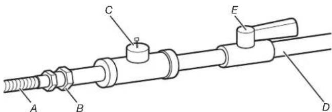
text_image
Technical diagram of a mechanical assembly with labeled components A, B, C, D, and EA. 3/8" flexible gas connector
B. 3/8" pipe to flare adapter fitting
C. 1/8" NPT minimum plugged tapping
D. 1/2" NPT gas supply line
E. Gas shut-off valve.
GAS SUPPLY CONNECTION REQUIREMENTS
Use an elbow and a 3/8" flare x 3/8" NPT adapter fitting between the flexible gas connector and the dryer gas pipe, as needed to avoid kinking.
■ Use only pipe-joint compound. Do not use TEFLON ^+ tape.
This dryer must be connected to the gas supply line with a listed flexible gas connector that complies with the standard for connectors for gas appliances, ANSI Z21.24 or CSA 6.10.
BURNER INPUT REQUIREMENTS
Elevations above 2,000 ft. (610 m):
■ When installed above 2,000 ft. (610 m) a 4% reduction of the burner Btu rating shown on the model/serial number plate is required for each 1,000 ft. (305 m) increase in elevation.
Gas supply pressure testing
■ The dryer must be disconnected from the gas supply piping system during pressure testing at pressures greater than 1/2 psi.
DRYER GAS PIPE
■ The gas pipe that comes out through the rear of your dryer has a 3/8" male pipe thread.
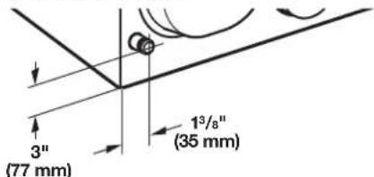
text_image
3" (77 mm) 1³/8" (35 mm)3/8" NPT dryer pipe
NOTE: For a garage installation, the gas pipe height must be an additional 18" (460 mm) from the floor.
INSTALL LEVELING LEGS
WARNING
Excessive Weight Hazard
Use two or more people to move and install dryer.
Failure to do so can result in back or other injury.
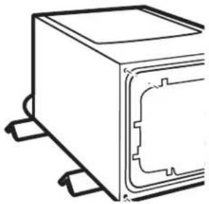
1. Prepare dryer for leveling legs
natural_image
Technical line drawing of a rectangular electronic component with mounting brackets (no text or symbols)Firmly grasp dryer body (not console panel) and gently lay dryer down on back cardboard corner posts.
IMPORTANT: If laying dryer on its back, use the cardboard corner posts the dryer was packed with to avoid damaging the back of the dryer.
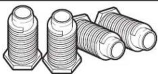
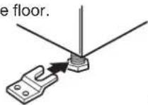
2. Screw in leveling legs
natural_image
Illustration of three different types of threaded fasteners or bolts (no text or symbols present)Using a wrench and tape measure, screw leveling legs into leg holes until bottom of foot is approximately 1" (25 mm) from bottom of dryer.
Now stand the dryer on its feet. Slide the dryer until it is close to its final location. Leave enough room to connect the exhaust vent.
For mobile home use:
Gas dryers must be securely fastened to the floor.
Mobile home installations require a Mobile Home Installation Hold-down Kit. For ordering information please reference the Use and Care Guide.
MAKE ELECTRICAL CONNECTION - U.S.A. ONLY (EFFECTUER LE RACCORDEMENT ÉLECTRIQUE - ÉTATS-UNIS SEULEMENT)
ELECTRICAL CONNECTION
Power Supply Cord
WARNING

Fire Hazard
Use a new UL listed 30 amp power supply cord.
Use a UL listed strain relief.
Disconnect power before making electrical connections.
Connect neutral wire (white or center wire) to center terminal (silver).
Ground wire (green or bare wire) must be connected to green ground connector.
Connect remaining 2 supply wires to remaining 2 terminals (gold).
Securely tighten all electrical connections.
Failure to do so can result in death, fire, or electrical shock.
Electrical Connection Options
1. Choose electrical connection type

Power supply cord 4-wire receptacle
(NEMA Type 14-30R):
Go to "Power Supply Cord Connection."
Power supply cord 3-wire receptacle
(NEMA Type 10-30R):
Go to "Power Supply Cord Connection."
4-wire direct connection:
Go to "Direct Wire Connection."
3-wire direct connection:
Go to "Direct Wire Connection."
NOTE: If local codes do not permit connection of a cabinet-ground conductor to neutral wire, go to "Optional 3-wire connection." This connection may be used with either a power supply cord or a direct wire connection.
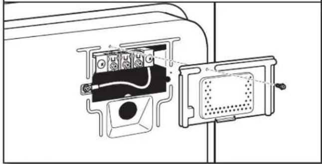
- Remove terminal block cover
natural_image
Technical line drawing of a device internal structure with no visible text or symbolsRemove hold-down screw and terminal block cover.
POWER SUPPLY CORD CONNECTION
Power Supply Cord Strain Relief
- Attach power supply cord strain relief
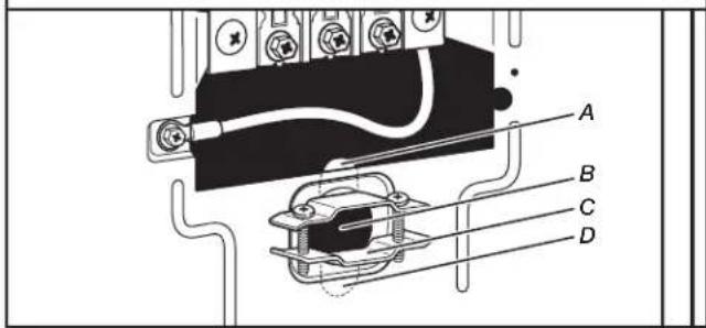
text_image
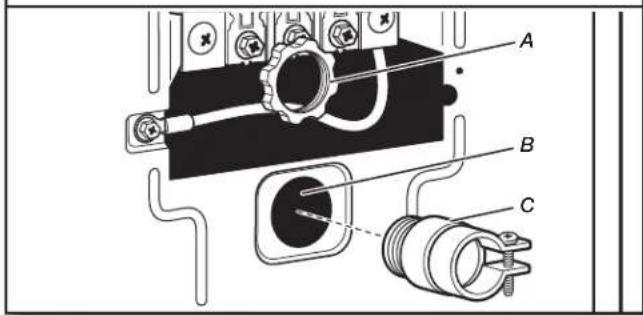
A B C DRemove the screws from a 3/4" (19 mm) UL-listed strain relief (UL marking on strain relief). Put the tabs of the two clamp sections (C) into the hole below the terminal block opening (B) so that one tab is pointing up (A) and the other is pointing down (D), and hold in place. Tighten strain relief screws just enough to hold the two clamp sections (C) together.
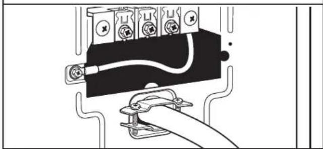
- Attach power supply cord to strain relief
natural_image
Line drawing of an electrical outlet with wires and connectors (no text or symbols)Put power supply cord through the strain relief. Be sure that the wire insulation on the power supply cord is inside the strain relief. The strain relief should have a tight fit with the dryer cabinet and be in a horizontal position. Do not further tighten strain relief screws at this point.
If your outlet looks like this:
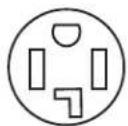
Power supply cord 4-wire receptacle (NEMA Type 14-30R):
Go to "4-Wire Power Supply Cord Connection".
Power supply cord 3-wire receptacle (NEMA Type 10-30R):
Go to "3-Wire Power Supply Cord Connection".
4-Wire Power Supply Cord Connection
IMPORTANT: A 4-wire connection is required for mobile homes and where local codes do not permit the use of 3-wire connections.
natural_image
Simple line drawing of an electrical outlet with three slots (no text or symbols)4-wire receptacle (NEMA-type 14-30R)
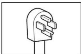
natural_image
Simple line drawing of a plug with three slots (no text or symbols)4-prong plug
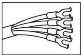
natural_image
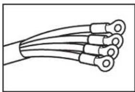
Diagram of a multi-wire electrical cable with multiple leads (no text or symbols)Spade terminals with upturned ends
natural_image
Line drawing of a multi-core cable with multiple leads (no text or symbols)Ring terminals
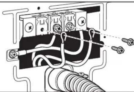
text_image
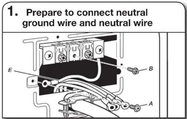
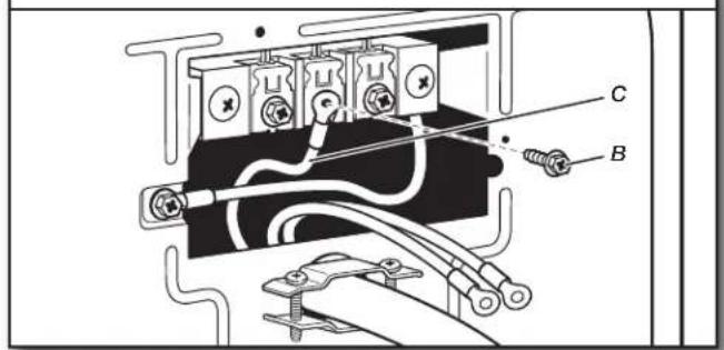
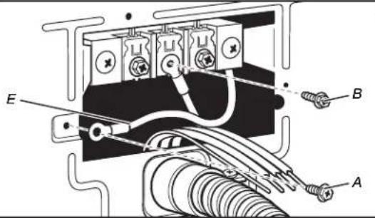
1. Prepare to connect neutral ground wire and neutral wireRemove center terminal block screw (B). Remove neutral ground wire (E) from external ground conductor screw (A). Reinstall ground conductor screw (A).
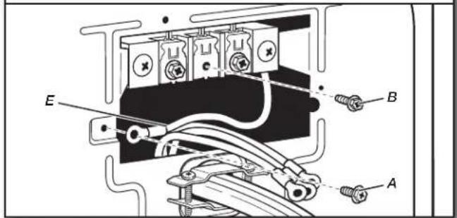
text_image
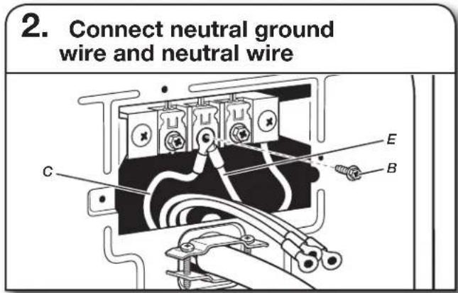
2. Connect neutral ground wire and neutral wire C E BConnect neutral ground wire (E) and neutral wire (white) (C) of power supply cord under center terminal block screw (B). Tighten screw.
text_image
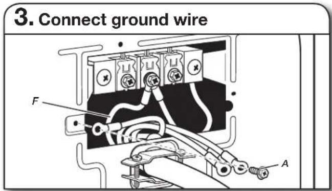
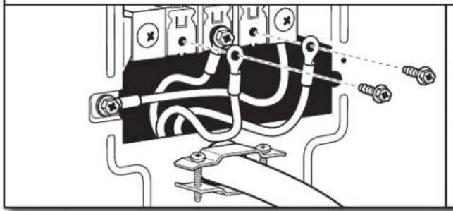
3. Connect ground wire F AConnect ground wire (F) (green or bare) of power supply cord to external ground conductor screw (A). Tighten screw.
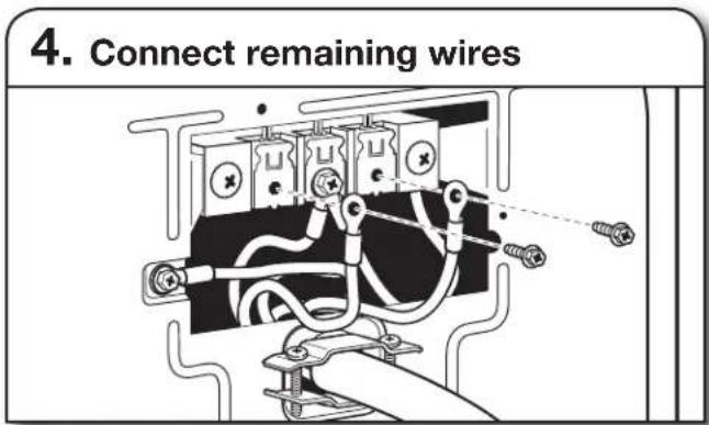
text_image
4. Connect remaining wiresConnect remaining wires to outer terminal block screws. Tighten screws. Finally, reinsert tab of terminal block cover into slot of dryer rear panel. Secure cover with hold-down screw. Now, go to "Venting Requirements."
3-Wire Power Supply Cord Connection
Use where local codes permit connecting cabinet-ground conductor to neutral wire.
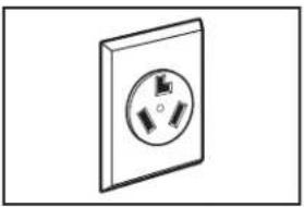
natural_image
Simple line drawing of a wall socket with three leads (no text or symbols)3-wire receptacle (NEMA-type 10-30R)
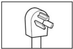
natural_image
Simple line drawing of a mechanical component with no text or symbols3-prong plug
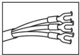
natural_image
Line drawing of a multi-wire electrical cable with multiple leads (no text or symbols)Spade terminals with upturned ends
natural_image
Line drawing of three coaxial cables with circular end caps (no text or symbols)Ring terminals
1. Remove center screw

natural_image
Technical diagram of an electrical contactor or relay with labeled component B (no text or symbols beyond label)Remove center terminal block screw (B).
2. Connect neutral wire
text_image
Technical diagram of an electrical switch or relay with labeled components A, B, and CConnect neutral wire (white or center) (C) of power supply cord to center terminal block screw (B). Tighten screw.
3. Connect remaining wires
natural_image
Pure electrical circuit lines without any symbolsConnect remaining wires to outer terminal block screws. Tighten screws. Finally, reinsert tab of terminal block cover into slot of dryer rear panel. Secure cover with hold-down screw. Now, go to "Venting Requirements."
DIRECT WIRE CONNECTION
WARNING

Fire Hazard
Use 10 gauge copper wire.
Use a UL listed strain relief.
Disconnect power before making electrical connections.
Connect neutral wire (white or center wire) to center terminal (silver).
Ground wire (green or bare wire) must be connected to green ground connector.
Connect remaining 2 supply wires to remaining 2 terminals (gold).
Securely tighten all electrical connections.
Failure to do so can result in death, fire, or electrical shock.
Direct Wire Strain Relief
1. Attach direct wire strain relief
text_image
Technical diagram of an electrical component with labeled parts A, B, and CUnscrew the removable conduit connector (A) and any screws from a 3/4" (19 mm) UL-listed strain relief (UL marking on strain relief). Put the threaded section of the strain relief (C) through the hole below the terminal block opening (B). Reaching inside the terminal block opening, screw the removable conduit connector (A) onto the strain relief threads.
2. Attach direct wire cable to strain relief
natural_image
Pure electrical circuit lines without any symbolsPut direct wire cable through the strain relief. The strain relief should have a tight fit with the dryer cabinet and be in a horizontal position. Tighten strain relief screw against the direct wire cable.
If your wiring looks like this:
4-wire direct connection:
Go to "4-Wire Direct Wire Connection" on this page.
3-wire direct connection:
Go to "3-Wire Direct Wire Connection" on page 14.
4-Wire Direct Wire Connection
IMPORTANT: A 4-wire connection is required for mobile homes and where local codes do not permit 3-wire connections.
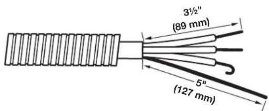
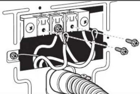
1. Prepare your 4-wire cable for direct connection
text_image
3½" (89 mm) 5" (127 mm)Direct wire cable must have 5 ft. (1.52 m) of extra length so dryer may be moved if needed.
Strip 5" (127 mm) of outer covering from end of cable, leaving bare ground wire at 5" (127 mm). Cut 1 ^1/2 " (38 mm) from remaining 3 wires. Strip insulation back 1" (25 mm). Shape ends of wires into hooks.
2. Prepare to connect neutral ground wire and neutral wire
text_image
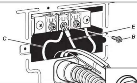
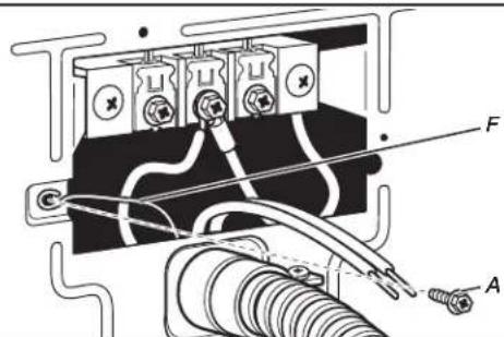
Technical diagram of an electrical component with labeled parts A, B, and E, showing connections and wiring.Remove center terminal block screw (B). Remove neutral ground wire (E) from external ground conductor screw (A).
3. Connect neutral ground wire and neutral wire
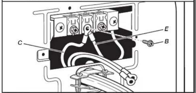
text_image
Technical diagram of an electrical switch or relay with labeled components A, B, C, and EConnect neutral ground wire (E) and place hooked end (hook facing right) of neutral wire (white or center wire) (C) of direct wire cable under center screw of terminal block (B). Squeeze hooked ends together and tighten screw.
4. Connect ground wire
text_image
Technical diagram of an electrical circuit with labeled components A and F, showing connections between switches, wires, and connectors.Connect ground wire (green or bare) (F) of direct wire cable to external ground conductor screw (A). Tighten screw.
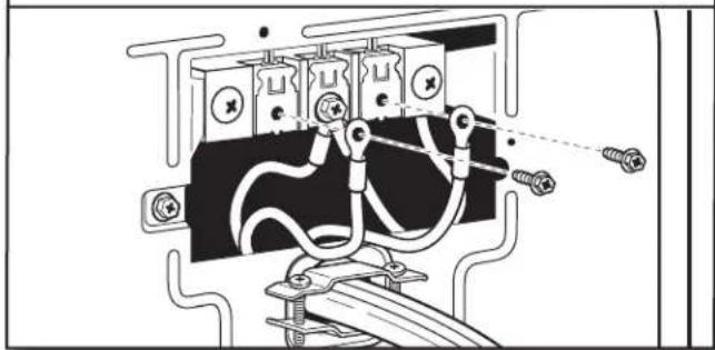
- Connect remaining wires
natural_image
Pure electrical circuit lines without any symbolsPlace hooked ends of remaining direct wire cable wires under outer terminal block screws (hooks facing right). Squeeze hooked ends together and tighten screws. Finally, reinsert tab of terminal block cover into slot of dryer rear panel. Secure cover with hold-down screw. Now, go to "Venting Requirements."
3-Wire Direct Wire Connection
Use where local codes permit connecting cabinet-ground conductor to neutral wire.
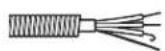
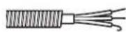
- Prepare your 3-wire cable for direct connection
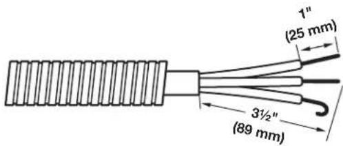
text_image
1" (25 mm) 3½" (89 mm)Direct wire cable must have 5 ft. (1.52 m) of extra length so dryer may be moved if needed.
Strip 3 ^1/2 " (89 mm) of outer covering from end of cable. Strip insulation back 1" (25 mm). If using 3-wire cable with ground wire, cut bare wire even with outer covering. Shape wire ends into hooks.
- Remove center screw
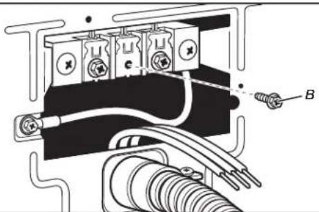
natural_image
Pure electrical circuit lines without any symbolsRemove center terminal block screw (B).
- Connect neutral wire
text_image
Technical diagram of an electrical component with labeled parts C and B, showing wiring and connections.Place hooked end of neutral wire (white or center) (C) of direct wire cable under center terminal block screw (B). Squeeze hooked end together. Tighten screw.

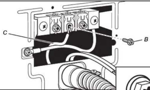
- Connect remaining wires
natural_image
Pure electrical circuit lines without any symbolsPlace hooked ends of remaining direct wire cable wires under outer terminal block screws (hooks facing right). Squeeze hooked ends together and tighten screws. Finally, reinsert tab of terminal block cover into slot of dryer rear panel. Secure cover with hold-down screw. Now, go to "Venting Requirements."
Optional 3-Wire Connection
You must verify with a qualified electrician that this grounding method is acceptable before connecting.
1. Prepare to connect neutral ground wire and neutral wire
text_image
E B ARemove center terminal block screw (B). Remove neutral ground wire (E) from external ground conductor screw (A).
2. Connect neutral ground wire and neutral wire
text_image
Technical diagram of an electrical component with labeled parts C, E, and BConnect neutral ground wire (E) and neutral wire (white or center wire) (C) of power supply cord or cable under center terminal block screw (B). Tighten screw.
3. Connect remaining wires
natural_image
Pure electrical circuit lines without any symbolsConnect remaining wires to outer terminal block screws. Tighten screws.
4. Connect external ground wire
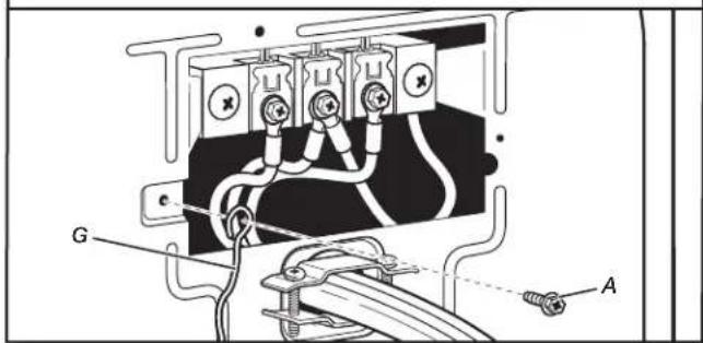
text_image
G AConnect a separate copper ground wire (G) from the external ground conductor screw (A) to an adequate ground. Finally, reinsert tab of terminal block cover into slot of dryer rear panel. Secure cover with hold-down screw. Now, go to "Venting Requirements."
MAKE GAS CONNECTION - U.S.A. AND CANADA
1. Connect gas supply to dryer
text_image
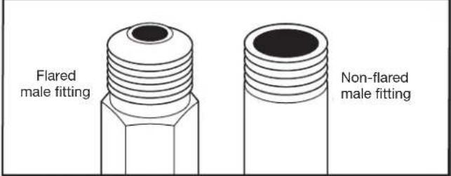
Flared male fitting Non-flared male fittingRemove red cap from gas pipe. Using a wrench to tighten, connect gas supply to dryer. Use pipe-joint compound on threads of all non-flared male fittings. If flexible metal tubing is used, be sure there are no kinks.
NOTE: For LP gas connections, you must use pipe-joint compound resistant to action of LP gas. Do not use TEFLON® tape.
2. Plan pipe fitting connection
text_image
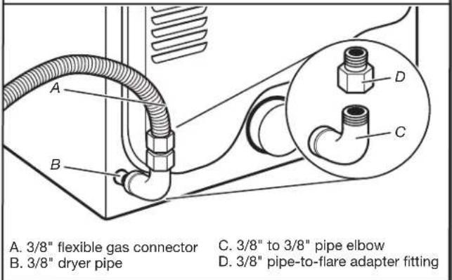
A. 3/8" flexible gas connector B. 3/8" dryer pipe C. 3/8" to 3/8" pipe elbow D. 3/8" pipe-to-flare adapter fittingA combination of pipe fittings must be used to connect dryer to existing gas line. Recommended connection is shown. Your connection may be different, according to supply line type, size, and location.
3. Open shut-off valve
text_image
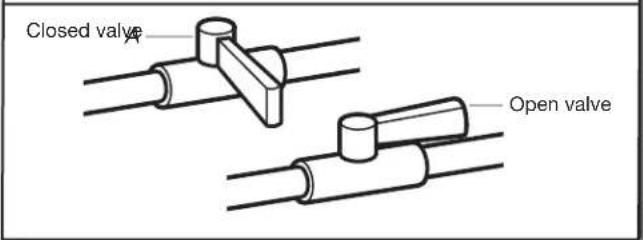
Closed valve Open valveOpen shut-off valve in supply line; valve is open when handle is parallel to gas pipe. Then, test all connections by brushing on an approved noncorrosive leak-detection solution. Bubbles will show a leak. Correct any leaks found.
VENTING
VENTING REQUIREMENTS
WARNING

Fire Hazard
Use a heavy metal vent.
Do not use a plastic vent.
Do not use a metal foil vent.
Failure to follow these instructions can result in death or fire.
WARNING: To reduce the risk of fire, this dryer MUST BE EXHAUSTED OUTDOORS.
IMPORTANT: Observe all governing codes and ordinances. Dryer exhaust must not be connected into any gas vent, chimney, wall, ceiling, attic, crawlspace, or a concealed space of a building. Only rigid or flexible metal vent shall be used for exhausting.
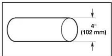
text_image
4" (102 mm)4" (102 mm) heavy metal exhaust vent
■ Only a 4" (102 mm) heavy metal exhaust vent and clamps may be used.
■ Do not use plastic or metal foil vent.
Rigid metal vent:
■ Recommended for best drying performance and to avoid crushing and kinking.
Flexible metal vent: (Acceptable only if accessible to clean)
■ Must be fully extended and supported in final dryer location.
■ Remove excess to avoid sagging and kinking that may result in reduced airflow and poor performance.
■ Do not install in enclosed walls, ceilings, or floors.
■ The total length should not exceed 7 ft. (2.4 m).
The length of flexible metal vent used must be included in the overall vent system design as shown in the "Vent System Chart."
NOTE: If using an existing vent system, clean lint from entire length of the system and make sure exhaust hood is not plugged with lint. Replace plastic or metal foil vents with rigid metal or flexible metal vents. Review "Vent System Chart" and, if necessary, modify existing vent system to achieve best drying performance.
Exhaust hoods:
■ Must be at least 12" (305 mm) from ground or any object that may obstruct exhaust (such as flowers, rocks, bushes, or snow).
Recommended Styles:
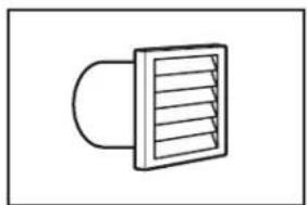
natural_image
Simple line drawing of a vent or airflow device with a curved inlet and rectangular outlet (no text or symbols)Louvered Hood
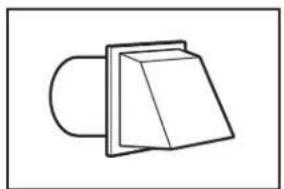
natural_image
Simple line drawing of a mechanical component or bracket (no text or symbols)Box Hood
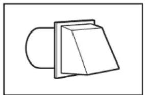
Acceptable Style:
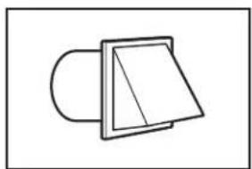
natural_image
Simple line drawing of a folded paper or sheet with a curved handle (no text or symbols)Angled Hood
Elbows:
■ 45° elbows provide better airflow than 90° elbows.
Recommended Styles:
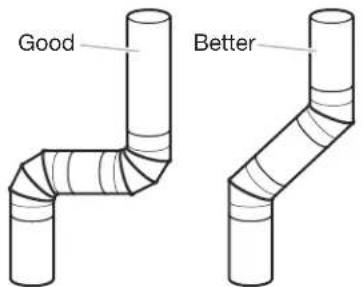
text_image
Good BetterClamps:
■ Use clamps to seal all joints.
■ Exhaust vent must not be connected or secured with screws or other fastening devices that extend into interior of duct and catch lint. Do not use duct tape.
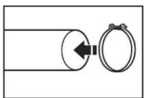
natural_image
Simple line drawing of a pipe connection with a circular component and ring (no text or symbols)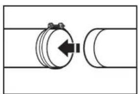
natural_image
Pure mechanical diagram showing a rotating component with an arrow indicating direction (no text or symbols)Improper venting can cause moisture and lint to collect indoors, which may result in:
■ Moisture damage to woodwork, furniture, paint, wallpaper, carpets, etc.
■ Housecleaning problems and health problems.
Vent products can be purchased from your dealer. For more information, see "Assistance or Service" section in your Use and Care Guide.
PLAN VENT SYSTEM
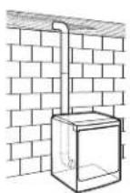
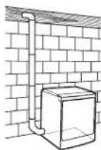
Recommended exhaust installations
Typical installations vent the dryer from the rear of the dryer. Other installations are possible.
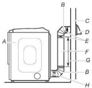
text_image
A B C D E F G B HA. Dryer
B. Elbow
C. Wall
D. Exhaust hood
E. Clamps
F. Rigid metal or flexible metal vent
G. Vent length necessary to connect elbows
H. Exhaust outlet
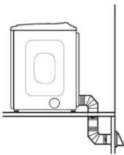
Optional exhaust installations:
WARNING

Fire Hazard
Cover unused exhaust holes with a manufacturer's exhaust cover kit.
Contact your local dealer.
Failure to follow these instructions can result in death, fire, electrical shock, or serious injury.
If you prefer, dryer may be converted to exhaust through the bottom and sides. You must contact your local dealer to have dryer converted.
A
B
natural_image
Simple line drawing of a 3D geometric shape with a cube beside it, no text or symbols present.C
A. Standard rear offset exhaust installation
B. Left- or right-side exhaust installation
C. Bottom exhaust installation
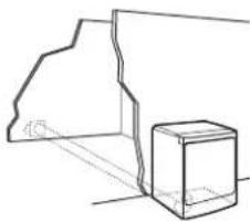
Special provisions for mobile homes:
Exhaust vent must be securely fastened to a noncombustible portion of mobile home and must not terminate beneath the mobile home. Terminate exhaust vent outside.
natural_image
Line drawing of a microwave oven mounted on a shelf with a staircase and ventilation unit (no text or symbols)Mobile Home Exhaust installation
Determine vent path:
■ Select route that will provide straightest and most direct path outdoors.
■ Plan installation to use fewest number of elbows and turns.
■ When using elbows or making turns, allow as much room as possible.
■ Bend vent gradually to avoid kinking.
■ Use as few 90° turns as possible.
Determine vent length and elbows needed for best drying performance:
■ Use the following "Vent System Chart" to determine the type of vent material and hood combinations acceptable to use.
NOTE: Do not use vent runs longer than those specified in the "Vent System Chart." Exhaust systems longer than those specified will:
■ Shorten life of dryer.
■ Reduce performance, resulting in longer drying times and increased energy usage.
The "Vent System Chart" provides venting requirements that will help achieve best drying performance.
| Vent System Chart | ||
| Number of 90° elbows | Type of vent | Angled hoods |
| 0 Rigid metal 64 ft. (20 m) | ||
| 1 Rigid metal 54 ft. (16.5 m) | ||
| 2 Rigid metal 44 ft. (13.4 m) | ||
| 3 Rigid metal 35 ft. (10.7 m) | ||
| 4 Rigid metal 27 ft. (8.2 m) | ||
NOTE: Bottom exhaust installations have a 90^ turn inside the dryer. To determine maximum exhaust length, add one 90^ turn to the chart.
INSTALL VENT SYSTEM
- Install exhaust hood
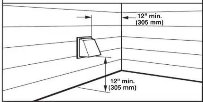
text_image
12" min. (305 mm) 12" min. (305 mm)Install exhaust hood and use caulking compound to seal exterior wall opening around exhaust hood.
- Connect vent to exhaust hood
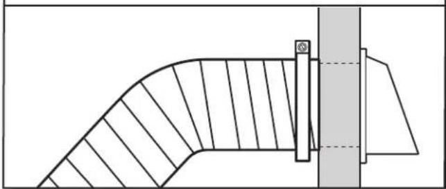
natural_image
Technical line drawing of a curved mechanical component with hatched fill and a vertical guide bar (no text or symbols)Vent must fit over the exhaust hood. Secure vent to exhaust hood with 4" (102 mm) clamp. Run vent to dryer location using straightest path possible. Avoid 90° turns. Use clamps to seal all joints. Do not use duct tape, screws, or other fastening devices that extend into interior of vent to secure vent, because they can catch lint.
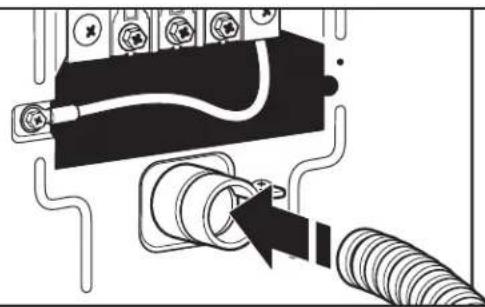
CONNECT INLET HOSES
For non-steam models, skip to "Connect Vent."
The dryer must be connected to the cold water faucet using the new inlet hoses. Do not use old hoses.
- Turn cold water off, remove and replace rubber washer
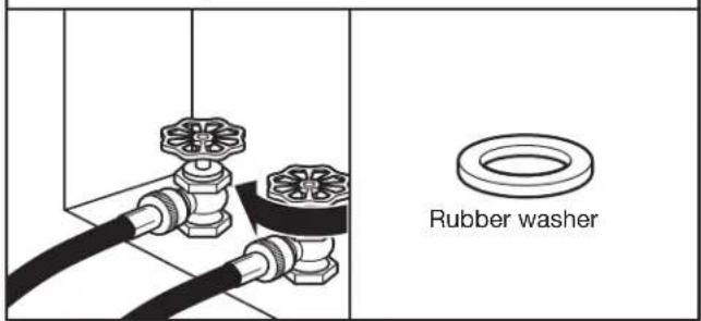
text_image
Rubber washerTurn cold water faucet off and remove washer inlet hose. Remove old rubber washer from inlet hose and replace with new rubber washer.
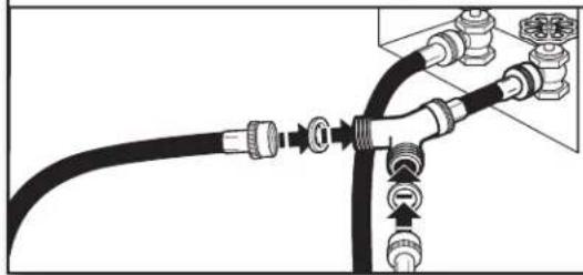
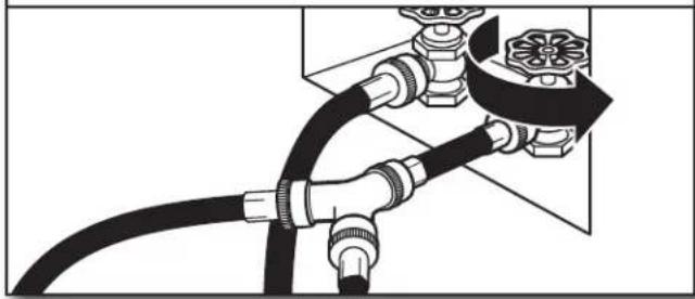
2. Attach short hose and "Y" connector
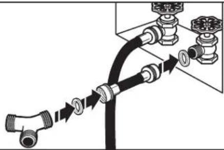
natural_image
Diagram of pipe fittings and connectors with directional arrows indicating connection (no text or symbols)Attach 2 ft (0.6 m) inlet hose to cold water faucet. Screw on coupling by hand until it is seated on faucet. Then attach "Y" connector to male end of the 2 ft (0.6 m) inlet hose. Screw on coupling by hand until it is seated on connector.
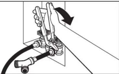
3. Tighten couplings
natural_image
Mechanical assembly diagram showing a hand operating a valve with hoses and a rotating arrow (no text or symbols)Using pliers, tighten the couplings with additional two-thirds turn.
NOTE: Do not overtighten. Damage to the coupling can result.
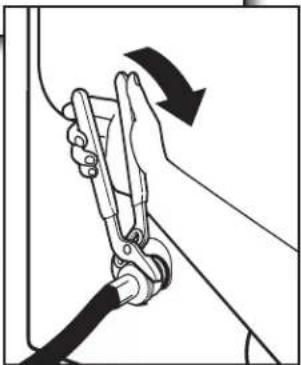
4. Attach long hose to "Y" connector and tighten couplings
natural_image
Pure diagram of a pipe connection with hoses and valves, no text or symbols presentAttach dryer 5 ft (1.5 m) inlet hose ends to the "Y" connector. Attach washer cold inlet hose to other side of "Y" connector. Screw on coupling by hand until it is seated on connector. Using pliers, tighten the couplings an additional two-thirds turn.
NOTE: Do not overtighten. Damage to the coupling can result.
5. Attach long hose to dryer fill valve and tighten coupling
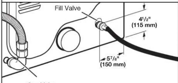
text_image
Fill Valve 4½" (115 mm) 5⁷/₈" (150 mm)Gas Valve
Attach other end of long hose to fill valve at bottom of dryer back panel. Screw on coupling by hand until it is seated on fill valve connector. Using pliers, tighten the couplings an additional two-thirds turn.
NOTE: Do not overtighten. Damage to the coupling can result.
natural_image
Illustration of a person using a cable to lift a car, showing motion direction (no text or symbols)6. Turn on cold water faucet
natural_image
Pure diagram of a pipe fitting with valves and fittings, no text or symbols presentCheck that the water faucet is turned on.
7. Check for leaks
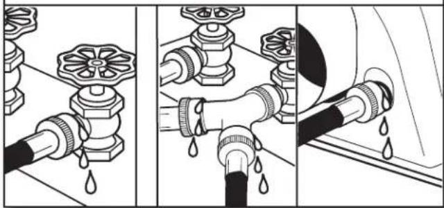
natural_image
Three-panel illustration showing pipe fittings and water droplets during installation (no text or symbols)Check for leaks around "Y" connector, faucets, and hoses.
CONNECT VENT
- Connect vent to exhaust outlet
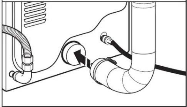
natural_image
Technical line drawing of a pipe system with hoses and valves (no text or symbols)Using a 4" (102 mm) clamp, connect vent to exhaust outlet in dryer. If connecting to existing vent, make sure vent is clean. Dryer vent must fit over dryer exhaust outlet and inside exhaust hood. Check that vent is secured to exhaust hood with a 4" (102 mm) clamp.
- Move dryer to final location
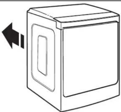
natural_image
Line drawing of a box with a double-headed arrow indicating left motion (no text or symbols)Move dryer to final location. Avoid crushing or kinking vent.
LEVEL DRYER
- Level Dryer
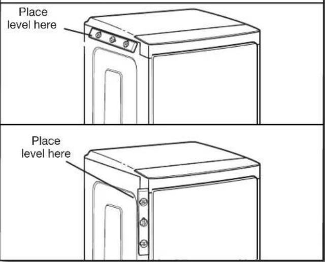
text_image
Place level here Place level hereCheck levelness of dryer from side to side. Repeat from front to back.
NOTE: The dryer must be level for the moisture sensing system to operate correctly.
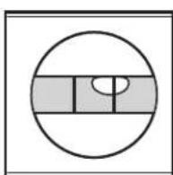
Not Level
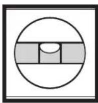
natural_image
Simple geometric diagram with a circle, horizontal bars, and a central semicircle (no text or symbols)LEVEL
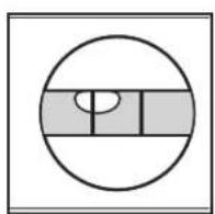
Not Level
- Adjust leveling legs
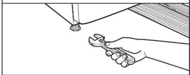
natural_image
Line drawing of a hand holding a wrench, with a tool above a surface (no text or symbols)If dryer is not level, prop up using a wood block. Use wrench to adjust legs up or down, and check again for levelness.
COMPLETE INSTALLATION CHECKLIST
☐ Check that all parts are now installed. If there is an extra part, go back through steps to see what was skipped.
☐ Check that you have all of your tools.
☐ Dispose of/recycle all packaging materials.
Check dryer's final location. Be sure vent is not crushed or kinked.
☐ Check that dryer is level. See “Level Dryer.”
☐ Remove film on console and any tape remaining on dryer.
☐ Wipe dryer drum interior thoroughly with a damp cloth to remove any dust.
Read "Dryer Use" in your Use and Care Guide.
Electric Models:
☐ For power supply cord installation, plug into a grounded outlet. For direct wire installation, turn on power.
Gas Models:
☐ Check that gas supply is on.
Check for leaks.
Steam models only:
Be sure the water faucets are on.
☐ Check for leaks around "Y" connector, faucet, and hoses.
☐ If you live in a hard water area, use of a water softener is recommended to control the buildup of scale through the water system in the dryer. Over time, the buildup of lime scale may clog different parts of the water system, which will reduce product performance. Excessive scale buildup may lead to the need for certain part replacement or repair.
All Models:
☐ Select a Timed Dry heated cycle, and start dryer. Do not select Air Only Temperature setting.
If dryer will not start, check the following:
- Controls are set in a running or "ON" position.
- Start button has been pushed firmly.
- Dryer is plugged into an outlet and/or electrical supply is connected.
- Household fuse is intact and tight, or circuit breaker has not tripped.
- Dryer door is closed.
This dryer automatically runs an installation diagnostic routine at the start of its first cycle.
If you receive an L2 code, there may be a problem with your home power supply keeping the dryer's heater from turning on. See "Troubleshooting."
If your Airflow screen reads "Check Vent," your dryer vent may be crushed or blocked. See "Troubleshooting."
NOTE: You may notice an odor when dryer is first heated. This odor is common when heating element is first used. The odor will go away.
REVERSE DOOR SWING
Tools needed:
Plastic putty knife
Min. 8" long TORX T20 ^® ^ screwdriver
2 Phillips screwdriver

Optional Assembly Kit Covers
You can change your door swing from a right-hinge opening to a left-hinge opening, if desired.
NOTE: To complete the door swing reversal exactly as seen in these instructions, a door reversal kit must be purchased. For ordering information, please reference the Use and Care Guide.
- Place a towel or soft cloth on a flat workspace such as a floor to avoid damaging the dryer's surface or the dryer door.
Remove door from dryer cabinet
- Open the dryer door.
- Use a plastic putty knife to remove the hinge covers and plastic covers from the front panel of the dryer. Set them aside.
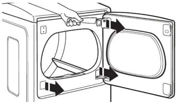
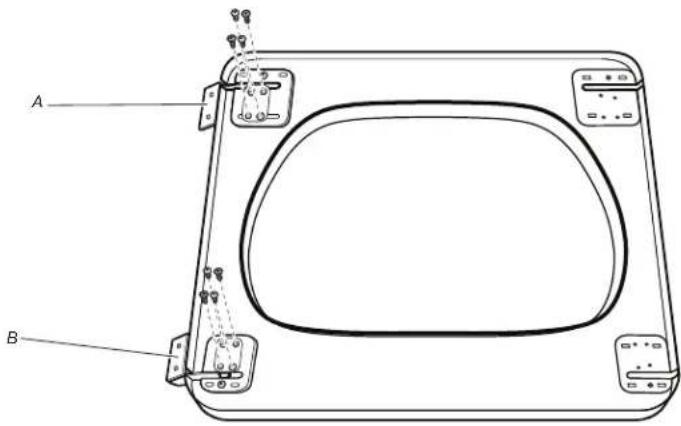
natural_image
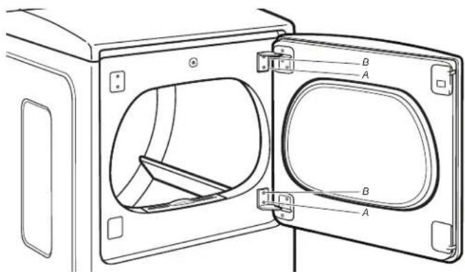
Line drawing of a door opening with internal compartments and arrows indicating movement (no text or symbols)- Using a T20 ^®† screwdriver, remove screws (A) and then screws (B) from each of the 2 hinges attaching the dryer door to the front panel of the dryer. Set the hinge screws off to the side for use in reinstalling the door.
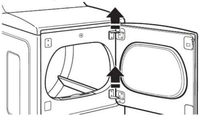
text_image
Technical diagram of a door frame with labeled components A and B, showing internal compartments and mounting points.- Remove the dryer door from the cabinet by lifting upward and out. Lay the door on a towel or a soft cloth you placed on a flat workspace.
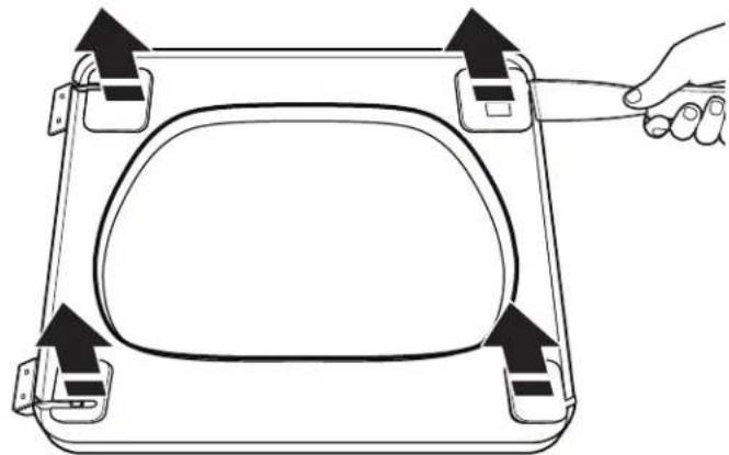
natural_image
Diagram of a door frame with internal compartments and directional arrows indicating movement or force (no text or symbols)- Use a plastic putty knife to remove the door hinge covers. Set them aside.
natural_image
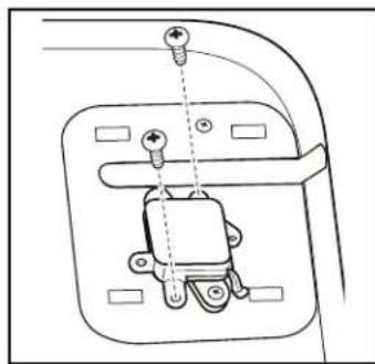
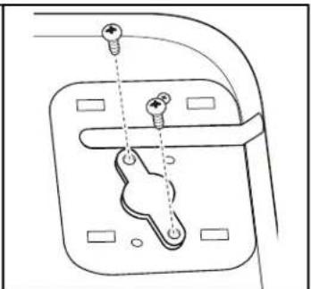
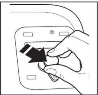
Diagram of a hand holding a device with four directional arrows indicating movement or force (no text or symbols present)- Using a #2 Phillips screwdriver, remove the remaining 4 screws from the hinges. Then remove hinges A and B and set both the screws and hinges aside.
text_image
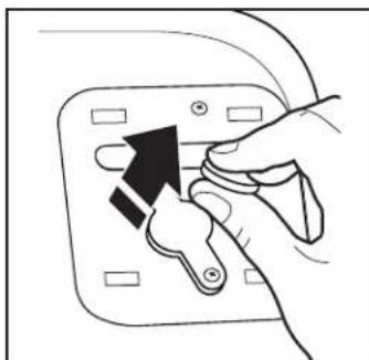
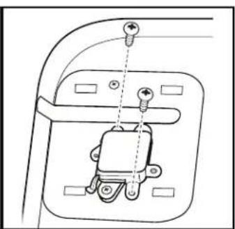
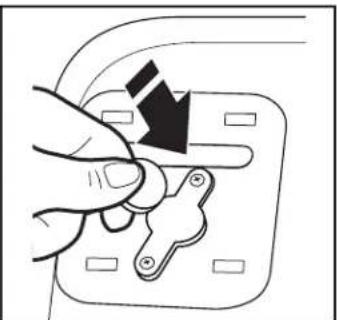
A B- Using a #2 Phillips screwdriver, remove the magnet latch and install it on the other side of the door.
text_image
Diagram of a device with labeled components and an inset showing internal components, likely illustrating a device's internal structure.After removing the magnet latch, move it to the opposite side of the door by reversing the steps above:
natural_image
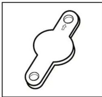
Simple line drawing of a mechanical bracket or clamp (no text or symbols)Make sure arrow on front of shim points up
natural_image
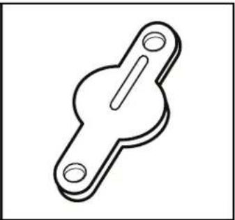
Simple line drawing of a mechanical bracket or clamp (no text or symbols)Rear of shim is embossed to ensure correct seating in opening
natural_image
Technical line drawing of a mechanical component with mounting holes and a central spring-like assembly (no text or symbols)Remove housing
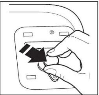
natural_image
Hand inserting a black arrow into a device panel (no text or symbols visible)Holding it tightly, slide magnet over
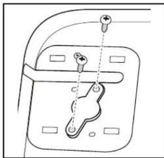
natural_image
Technical line drawing of a mechanical component with mounting holes and fasteners (no text or symbols)Screw on shim
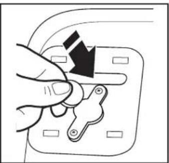
natural_image
Hand inserting a black arrow into a small electrical socket (no text or symbols visible)Holding magnet tightly, place edge of magnet on shim and lower magnet so edge rests flatly on shim
natural_image
Hand inserting a key into an electrical socket (no text or symbols visible)Holding it tightly, lift magnet off of shim
natural_image
Diagram of a mechanical switch or bracket with two screws and a central handle (no text or symbols)Remove shim

natural_image
Hand holding a small mechanical component with an arrow indicating force (no text or symbols)Holding magnet tightly, slide into place
natural_image
Technical line drawing of a mechanical component with mounting holes and a central housing (no text or symbols)Screw on housing
IMPORTANT: Because the magnetic force is strong, it is important to maintain a firm grip and to slide the magnet with a steady, gradual movement. Doing so can keep the magnet from reattaching to the metal surface and breaking, or from possibly pinching your fingers.
REINSTALL HINGES ON DOOR
- Using the screws you set aside, reinstall hinge B (removed from the lower-left corner of the door) in the upper-right corner. Tighten all screws.
- Using the screws you set aside, reinstall hinge A (removed from the upper-left corner of the door) in the lower-right corner. Tighten all screws.
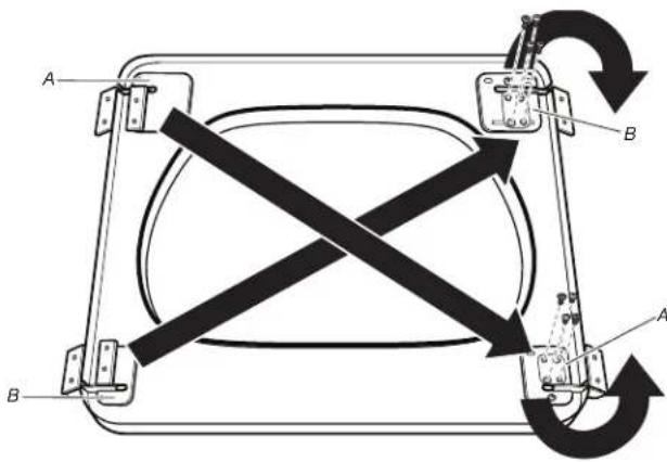
text_image
A B A B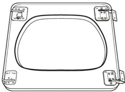
natural_image
Line drawing of a rectangular frame with rounded corners and mounting clips (no text or symbols)- Replace the door hinge covers.

natural_image
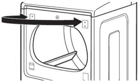
Diagram of a vehicle door frame with directional arrows indicating movement or force (no text or symbols)REVERSE STRIKE PLATE
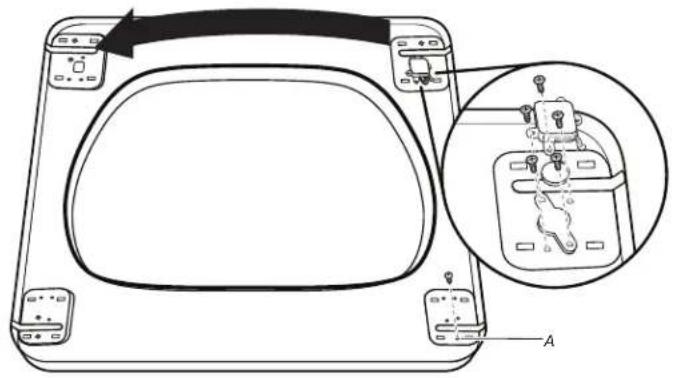
- Using a T20® screwdriver, remove the two screws securing the strike plate and move the strike plate from the left side of the dryer cabinet to the right side, securing it with the removed screws.
natural_image
Line drawing of a door frame with an arrow indicating direction, showing internal components (no text or symbols)- Hang the door on the unit by placing set pin in dryer cabinet hole and sliding door down. Using a Phillips screwdriver, install screws 1 and 3 and then screws 2 and 4. Tighten all hinge screws.
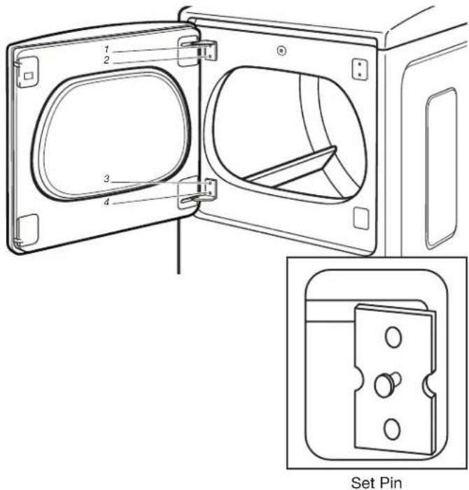
text_image
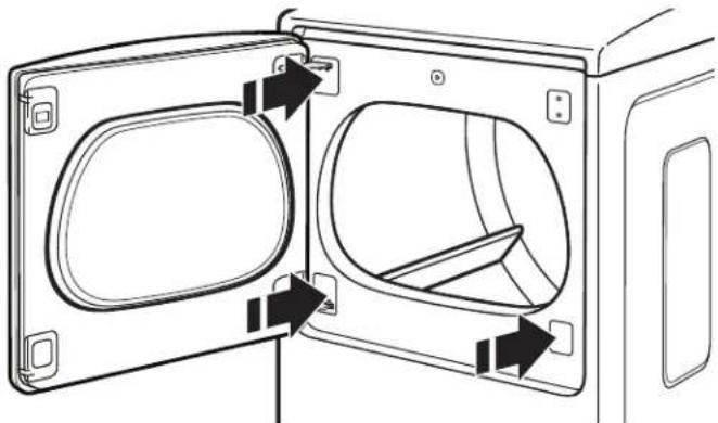
1 2 3 4 Set Pin- Install the plastic cover from the accessory kit into the space where the lower hinge was removed. Place the plastic hinge covers over the exposed hinges.
natural_image
Diagram of a door frame with two internal compartments and directional arrows indicating movement or force (no text or symbols)natural_image
Line drawing of a screwdriver with a flat head and threaded shaft (no text or symbols)natural_image
Line drawing of an adjustable wrench (no text or symbols)natural_image
Simple diagram with three circular symbols inside a rectangular box (no text or labels)Niveau
natural_image
Two interlocked metal rings with clips attached (no text or symbols)Brides de conduit
natural_image
Simple line drawing of a tool or grip (no text or symbols)natural_image
Two hand tools: a cylindrical tool and a pair of sawhers (no text or symbols)natural_image
Line drawing of a pair of pliers (no text or symbols)natural_image
Simple line drawing of a screwdriver with a handle and shaft (no text or symbols)natural_image
Simple line drawing of a screwdriver (no text or symbols)natural_image
Line drawing of a pair of pliers with metal fasteners (no text or symbols)natural_image
Simple line drawing of a measuring tape (no text or symbols)Mètre-ruban
natural_image
Line drawing of a pair of pliers with no text or symbolsPince
natural_image
Line drawing of an adjustable wrench (no text or symbols)natural_image
Line drawing of an adjustable wrench (no text or symbols)natural_image
Simple line drawing of a jar with a lid and handle (no text or symbols)natural_image
Illustration of three different types of threaded fasteners or bolts (no text or symbols present)natural_image
Simple black curved line with two metallic connectors (no text or symbols)natural_image
Coiled black cable with two metallic connectors (no text or symbols visible)text_image
81/2" (218 mm) -143/8" (365 mm)text_image
29" (737 mm) 5"1/8" (150 mm) 4"1/2" (115 mm) 3" (77 mm) 13/8" (35 mm) 14"1/2" (370 mm) 3"1/2" (93 mm)text_image
81/2" (218 mm) 143/8" (365 mm)natural_image
Simple line drawing of a rectangular electronic component with mounting holes (no text or symbols)natural_image
Illustration of three threaded fasteners with hexagonal bases (no text or symbols)text_image
4" (102 mm)natural_image
Simple line drawing of a vent with airflow or ventilation (no text or symbols)Clapet à persiennes
natural_image
Simple line drawing of a mechanical component or bracket (no text or symbols)natural_image
Simple line drawing of a folded paper or sheet with a curved handle (no text or symbols)Clapet incliné
Coudes :
natural_image
Simple line drawing of a ring with a double-headed arrow indicating direction (no text or symbols)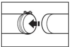
natural_image
Pure mechanical diagram showing a cylindrical component connected to a curved pipe (no text or symbols)natural_image
Simple line drawing of a 3D geometric shape with a cube beside it (no text or symbols)C
natural_image
Line drawing of a kitchen appliance with a staircase and door (no text or symbols)natural_image
Technical line drawing of a mechanical component with hatched fill and alignment markers (no text or symbols)natural_image
Diagram of pipe fittings and connectors in a piping system (no text or labels)natural_image
Mechanical assembly diagram showing a hand operating a valve with hoses and tubing (no text or symbols)natural_image
Pure diagram of a cable being inserted into a connector with multiple connectors (no text or symbols)natural_image
Illustration of a person using a cable to lift a car, showing motion direction (no text or symbols)natural_image
Pure diagram of a pipe connection with valves and fittings, no text or symbols presentnatural_image
Three-panel illustration showing pipe fittings and water droplets during installation (no text or symbols)natural_image
Technical diagram of a pipe system with hoses and tubing (no text or labels)natural_image
Line drawing of a box with a door and lid, showing an arrow pointing left (no text or symbols)natural_image
Line drawing of a microwave oven with front panel and door (no text or symbols)natural_image
Line drawing of a cabinet or rack unit with mounting holes and a side panel (no text or symbols)natural_image
Line drawing of a hand holding a wrench, with a tool above a screw and a wooden surface (no text or symbols)natural_image
Line drawing of a door opening with arrows indicating internal components (no text or symbols)text_image
Technical diagram of a door frame with labeled components A and B, showing internal compartments and structural details.natural_image
Diagram of a door opening with arrows indicating direction of movement or force (no text or symbols present)natural_image
Diagram of a hand holding a tool interacting with a rectangular device (no text or symbols present)natural_image
Line drawing of a device casing with a close-up inset showing internal components (no text or symbols)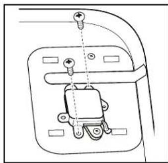
natural_image
Technical line drawing of a mechanical component with screws and mounting holes (no text or symbols)Retirer le logement
natural_image
Hand inserting a black arrow into a device panel (no text or symbols visible)natural_image
Hand inserting a black arrow into a switch panel (no text or symbols visible)natural_image
Technical line drawing of a mechanical component with two screws and a handle (no text or symbols)Enlever la cale
natural_image
Isometric line drawing of a mechanical bracket or clamp (no text or symbols)natural_image
Simple line drawing of a mechanical bracket or clamp (no text or symbols)natural_image
Pure mechanical diagram showing a bracket with screws and a handle, no text or symbols presentViser la cale
natural_image
Hand pressing a black arrow on a switch component (no text or symbols visible)natural_image
Hand holding a switch component with a black arrow indicating the action (no text or symbols present)natural_image
Technical diagram of a mechanical assembly with no visible text or symbolsnatural_image
Technical line drawing of a rectangular frame with rounded corners and mounting brackets (no text or symbols)natural_image
Diagram of a vehicle door frame with directional arrows indicating movement or force (no text or symbols)INVERSION DE LA GÂCHE
natural_image
Line drawing of a door with a circular opening and directional arrow indicating motion (no text or symbols)text_image
Technical diagram of a door frame with labeled components and an inset view of the door panel.Goupille à demeure
natural_image
Diagram of a door opening with internal compartments and directional arrows indicating movement (no text or symbols)NOTES