
OCEAISH750W - Tumble dryer OCEANIC - Free user manual and instructions
Find the device manual for free OCEAISH750W OCEANIC in PDF.

| Brand | Oceanic |
| Model | OCEAISH750W (EKA-140-54) |
| Product type | Electric towel warmer |
| Rated power | 700 W |
| Rated voltage | 220-240 V~ |
| Rated frequency | 50-60 Hz |
| IP protection rating | IP24 |
| Electrical class | Class II |
| Number of programs | 10 programs (4 with pilot wire) |
| Operating modes | Comfort, Economy, Frost protection, Timer, Pilot |
| Comfort temperature range | 7 °C to 30 °C (default 19 °C) |
| Economy temperature range | 7 °C to 30 °C (default 15.5 °C) |
| Frost protection temperature | 7 °C |
| Special functions | Open window detection, Anti-scald, Child lock, Fault memory |
| Control | Electronic with weekly programmer |
| Electrical connection | Wall box, pilot wire (optional), RCD 30 mA |
| Installation | Vertical wall mounting, minimum distance from floor 600 mm |
| Material | Steel (estimate) |
| Dimensions (W x H x D) | Not specified |
| Weight | Not specified |
| Maintenance | Clean with damp cloth, no solvents |
| Warranty | 24 months |
Frequently Asked Questions - OCEAISH750W OCEANIC
User questions about OCEAISH750W OCEANIC
0 question about this device. Answer the ones you know or ask your own.
Ask a new question about this device
Download the instructions for your Tumble dryer in PDF format for free! Find your manual OCEAISH750W - OCEANIC and take your electronic device back in hand. On this page are published all the documents necessary for the use of your device. OCEAISH750W by OCEANIC.
USER MANUAL OCEAISH750W OCEANIC
natural_image
White horizontal heater with slats and a small logo on the right side (no text or symbols on the heater itself)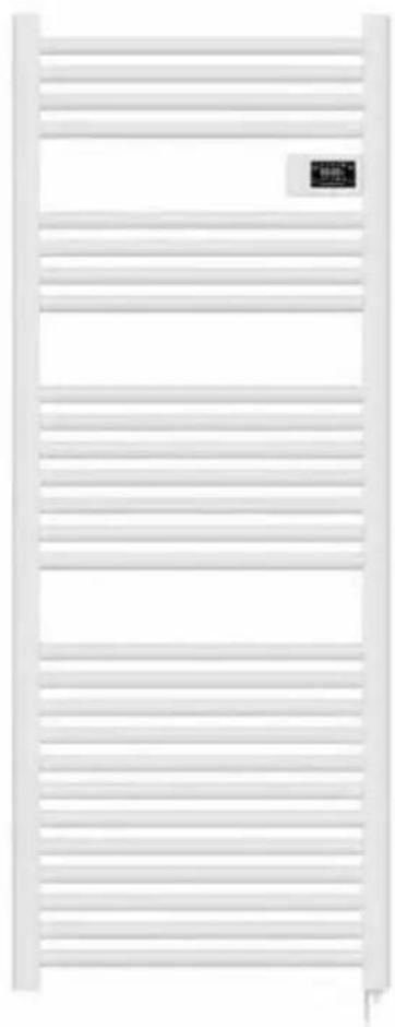
natural_image
White horizontal heater with slats and a small black logo on the right side (no text or symbols visible)Electric towel radiator
OCEAISH500W
OCEAISH750W
CONSIGNES DE SÉCURITÉ
MERCI DE BIEN VQULOIR LIRE LES CONSIGNES DE SECURITÉ ATTENTIVEMENT AVANT D'UTILISER L'APPAREIL. CONSERVEZ-LES POUR TOUTE CONSULTATION ULTERIEURE.
natural_image
Simple line drawing of a ring with two concentric circles, no text or symbols present4×4×4×
SCHÉMA D'INSTALLATION

DANGER!
MISE EN PLACE DU PRODUIT
natural_image
Simple 3D diagram showing a pencil inside an oval with a pointer and two arrows pointing to it, surrounded by scattered dots (no text or symbols)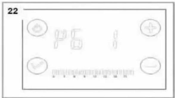
CONDITIONS DE GARANTIE
- This appliance can be used by children aged from 8 years and above and persons with reduced physical, sensory or mental capabilities or lack of experience and knowledge if they have been given supervision or instruction concerning use of the appliance in a safe way and understand the hazards involved. Children shall not play with the appliance. Cleaning and user maintenance shall not be made by children without supervision.
- Children of less than 3 years should be kept away unless continuously supervised.
- Children aged from 3 years and less than 8 years shall only switch on/off the appliance provided that it has been placed or installed in its intended normal operating position and they have been given supervision or instruction concerning use of the appliance in a safe way and understand the hazards involved.
- Children aged from 3 years and less than 8 years shall not plug in, regulate and clean the appliance or perform user maintenance.
- CAUTION — Some parts of this product can become very hot and cause burns. Particular attention has to be given where children and vulnerable people are present.
-
If the power cord is damaged, it must be replaced by the manufacturer, its service agent or similarly qualified persons in order to avoid a hazard.
-
The appliance should not be placed immediately below a socket.
- The heater must not be located directly in front of a socket outlet.
-
This appliance is intended only for drying textiles that have been washed with water.
-
WARNING: In order to avoid a hazard for very young children, this appliance should be installed so that the lowest heated rail is at least 600 mm above the floor.
- Do not use this heater with a programmer, timer, separate remote control system or any other device that turns on the heater automatically because there is a risk of fire if the device is covered or placed incorrectly. Use only a remote control device connected by the pilot cable.
- The device must be powered by a Residual Current Device (RCD) with a rated operating differential current of not more than 30 mA.
- The device must be connected to a circuit independent electric protected by a bipolar circuit breaker according to the standard electrical installation NF C 15-100.
- The heater must be installed so that switches and other control devices can not be touched by a person in the bath or shower.
- A means of disconnection from the power supply having a contact opening distance of all poles must be included in the fixed wiring in accordance with the installation requirements.
- For your safety, the device is equipped with a thermal circuit breaker. In the event of overheating, the power supply will be cut off.
- With respect to the details of how to install the appliance onto the wall, refer to the "INSTALLATION" section.
- Regarding the detailed information on the connection of the electric cable, refer to the section "ELECTRICAL CONNECTION".
INSTALLATION
RECOMMENDATIONS IMPORTANT READ BEFORE INSTALLATION
- Do not install the unit directly below a socket.
- Do not use the appliance outdoors.
- Do not install the unit in an air current that could disrupt its regulation.
- Do not place the unit near a barrier limiting the airflow around it.
- Attach the heater vertically to the wall as described below.
- Choose screws and plugs suitable for the wall material and weight of the unit.
RECOMMENDATIONS FOR WALL MOUNTING
Do not make any changes to the unit or its mounting bracket on the wall!
Before installing the device, check the condition of the wall on which it will be fixed: the wall must be in good condition, it must not show any damage (cracks, sagging, humidity, ...).
Do not drill holes near old holes, even when they are closed.
It is imperative that you consult a building professional to use the anchoring system (screws, dowels, etc.) appropriate for the material that constitutes your wall, as well as the weight of the appliance. Observe the diameter of the fixing screws indicated in this manual.
Do not modify the holes for securing the unit or its mounting bracket to the wall.
Drill the wall with a drill of the appropriate size for the anchoring system.
Remove debris and dust.
Regularly check the mounting points of the device on the wall. Tighten them if necessary.
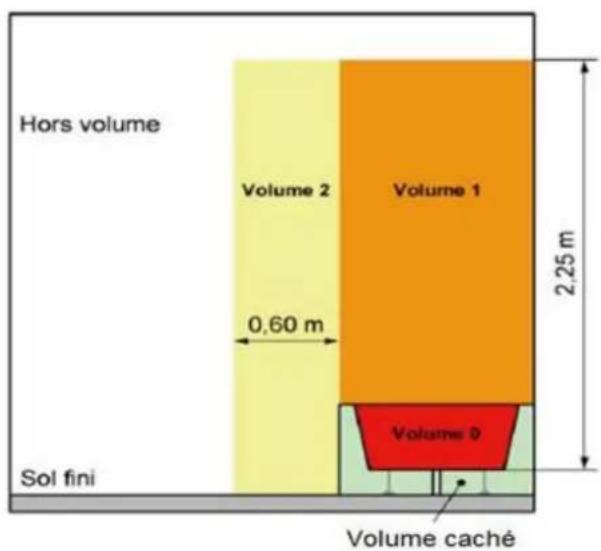
INSTALLATION IN THE BATHROOM
Warning: this product shall be used in volume 2 and out of volume only according to the national wiring rules (For France NF C 15-100)
Note: The drawing is for reference only.
We suggest that you contact a professional electrician for assistance.
ELECTRICAL CONNECTION
CAUTION: Before working, turn off the electricity at the main circuit breaker.
- The installation must be carried out in the rules of the art and meet the standards in force in the country (NF C 15-100 in France).
- The unit must be connected to a standard wall box placed at least 60 cm from the floor.
- The appliance must not be connected to an outlet with a power plug.
- The appliance must be supplied through a residual current device (RCD) having a rated residual operating current not exceeding 30 mA.
- The appliance must not be connected to the earth wire (yellow and green wire).
- Blue or light gray wire connect to Neutral (220-240V) Brown or red wire connect to Phase (220-240V)
- Black wire connect to pilot wire. (Optional function to use in case of control by pilot wire box)
- Black wire to be connected to the pilot wire. Optional function to be used only if your home's electrical installation includes a wired pilot box.
- Attention! Some parts of the device may become hot during use. Babies and children are particularly vulnerable to burns.

Read and observe the instructions for use before using the product for the first time.

Do not overload the device by hanging too many towels or clothes on it. Do not cover the device tightly. Fire hazard!
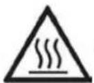
Caution, hot surface! Danger of being burnt!
INSTALLATION OF THE DEVICE
To install the device please provide:
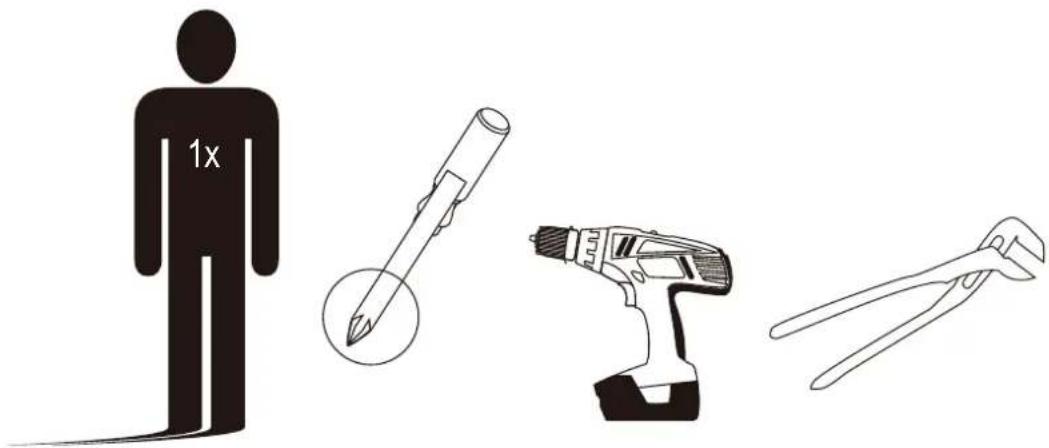
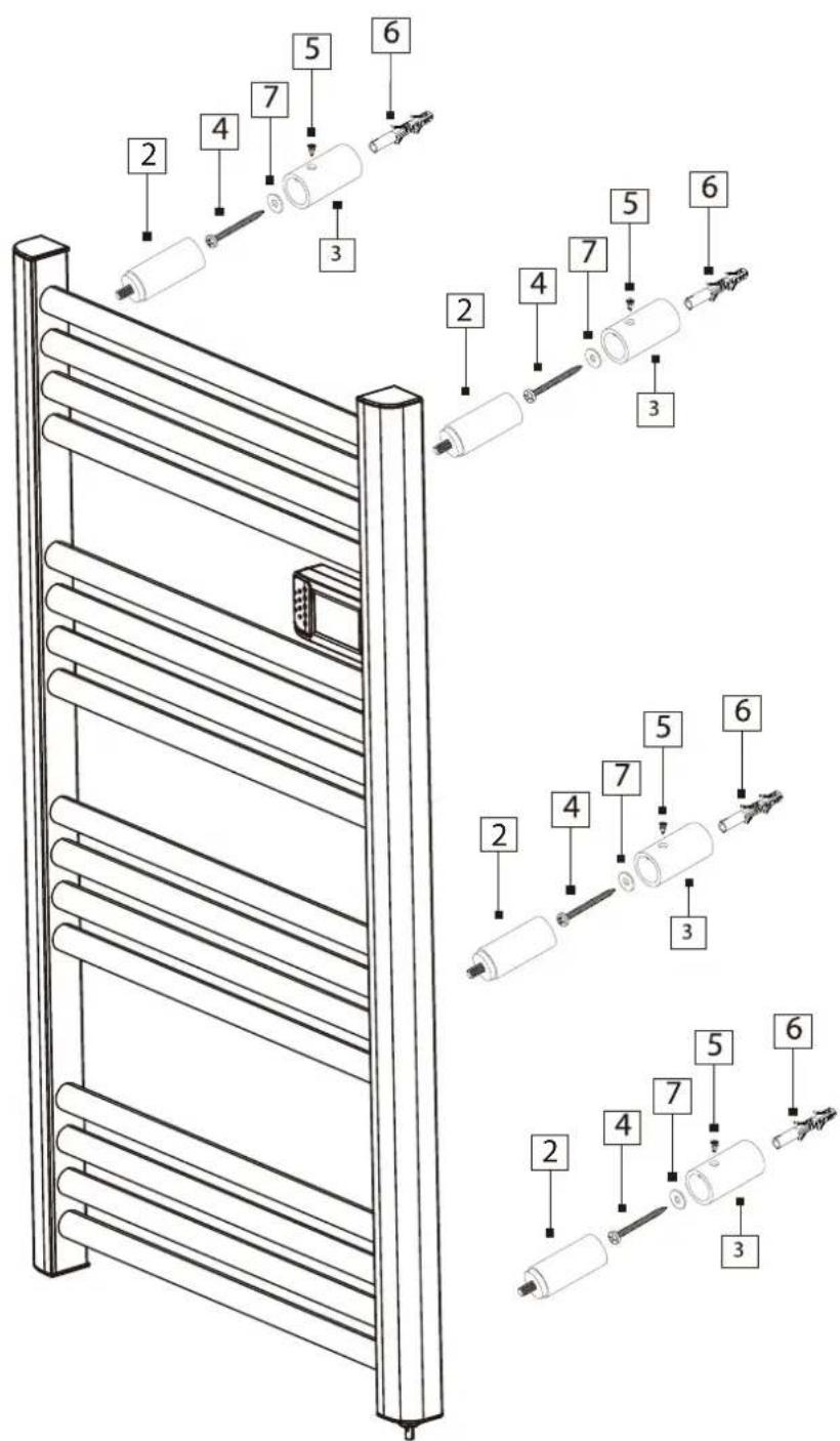
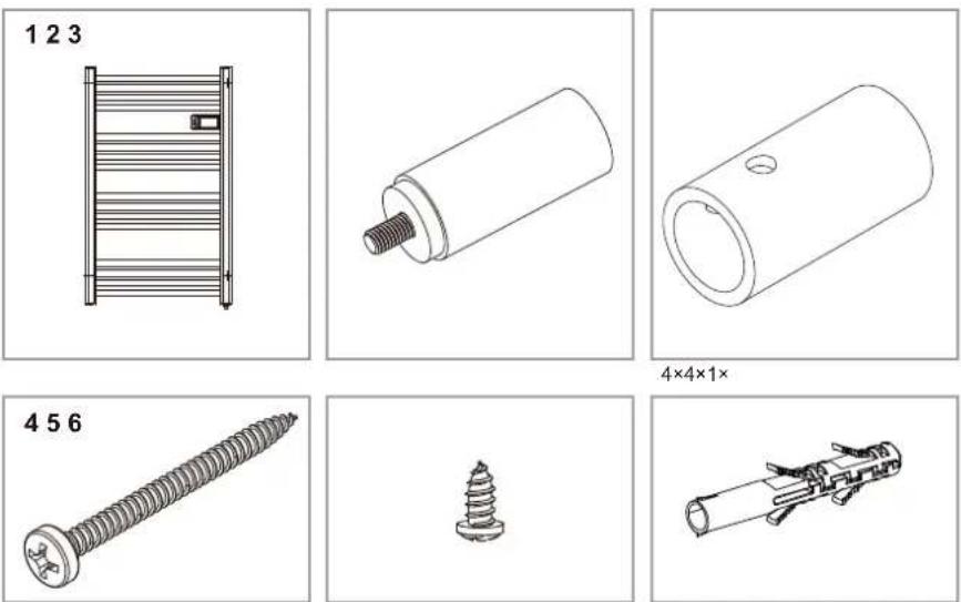
LIST OF PARTS
- Electric heater
- Wall bracket
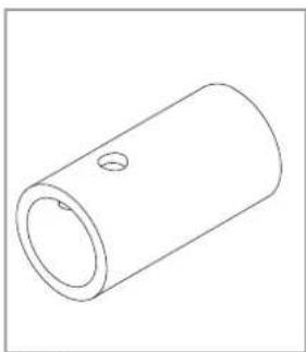
- Bracket housing
- Long wall screw
- Short connecting screw
- Wall plug
- Pad
natural_image
Technical drawings of mechanical components including a rack, cylindrical parts, and screw (no text or symbols)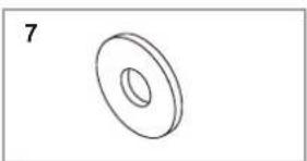
natural_image
Simple line drawing of a ring with a central hole, no text or symbols present4×4×4×
natural_image
Simple line drawing of a cylindrical mechanical part with a hole (no text or symbols)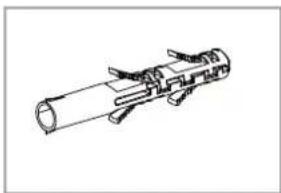
natural_image
Technical line drawing of a mechanical component with cylindrical body and attached clamps (no text or symbols)4×4×4×

DANGER! Danger of electric shock! Before drilling the holes, make sure that there are no electrical or other lines in the wall.

DANGER! Risk of injury! The device may not be mounted directly below a wall outlet. Danger of cable fires!

WARNING! Property damage! When drilling, ensure that sufficient space is left between the hole and the water lines located in the vicinity. There is risk of water damage.
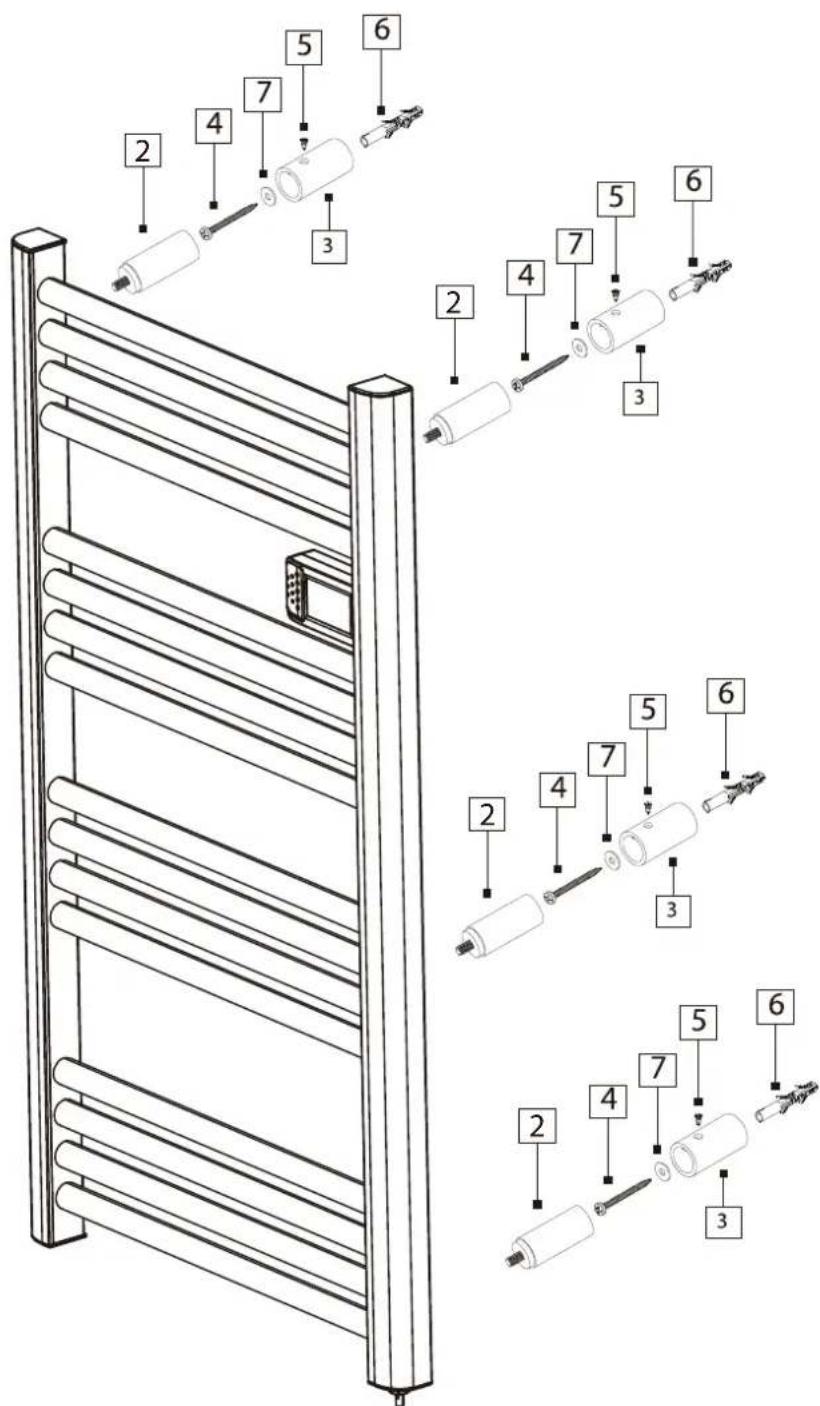
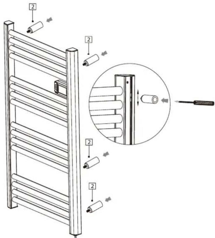
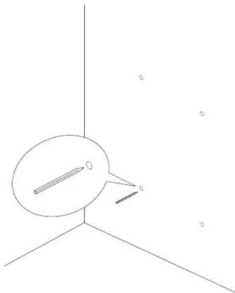
PRODUCT INSTALLATION
- Place the brackets with screws in the four holes of the device. Please note that the built-in slider allows you to adjust the height of the brackets. The maximum distance between the upper and lower brackets is equal to the total length of the device. Make sure that horizontally brackets on the right and left are located at the same height.
- Before drilling holes, mark their positions on the wall.
natural_image
Simple line drawing of a pencil and a ruler on a 3D coordinate axis (no text or symbols)-
Use a suitable drill bit to drill the holes.
-
Insert the appropriate plugs into the holes, then fix the support boxes as shown in the diagram below using the long wisps and washers.
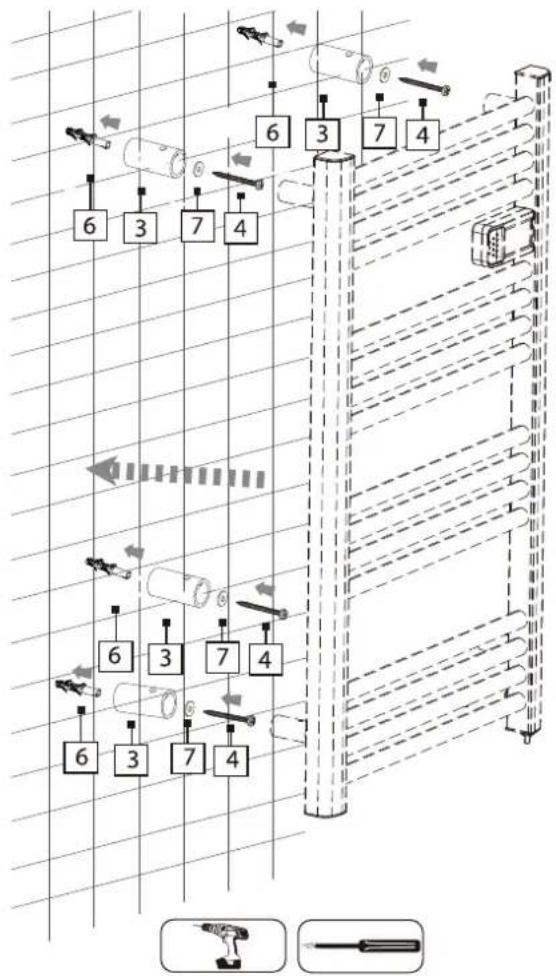
flowchart
graph TD
    A["Component 6"] --> B["Component 3"]
    B --> C["Component 7"]
    C --> D["Component 4"]
    D --> E["Component 6"]
    E --> F["Component 3"]
    F --> G["Component 7"]
    G --> H["Component 4"]
    H --> I["Component 6"]
    I --> J["Component 3"]
    J --> K["Component 7"]
    K --> L["Component 4"]
    L --> M["Component 6"]
    M --> N["Component 3"]
    N --> O["Component 7"]
    O --> P["Component 4"]
    P --> Q["Component 6"]
    Q --> R["Component 3"]
    R --> S["Component 7"]
    S --> T["Component 4"]
    T --> U["Component 6"]
    U --> V["Component 3"]
    V --> W["Component 7"]
    W --> X["Component 4"]
    X --> Y["Component 6"]
    Y --> Z["Component 3"]
    Z --> AA["Component 7"]
    AA --> AB["Component 4"]
DEVICE OPERATION
Before each start-up, check the condition of the device.

DANGER! Risk of injury! The device may only be turned on if no faults or damage to the product, cable and plug have been found.
Check if all machine parts are securely mounted.
Before connecting, check that all switches are in the [0] position.
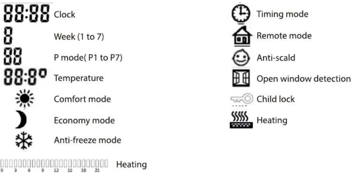
CONTROL PANEL BUTTONS

ON/ OFF switch

Mode switch

Temperature and time increase switch

Temperature and time decrease switch
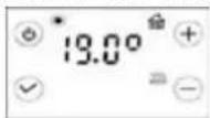
COMFORT MODE
This mode allows you to set the desired temperature during the day. The temperature range is from 7^ C to 30^ C. The default temperature is 19^ C.
ECONOMY MODE
This mode allows you to set the desired temperature at night. The temperature range is from 7 °C to 30 °C. The maximum temperature must not exceed the comfort temperature. The default temperature is 15.5 °C. Press [+] to increase the temperature, [-] to decrease it.
ANTI FREEZE MODE
This mode allows you to maintain a positive temperature in the room. Use the switch button to enter the anti-freeze mode. Display will show symbol of a snowflake. The temperature is kept at 7^ C. The device turns on when the temperature drops below this level and turns off automatically when it reaches a temperature of 7^ C.
TIMER
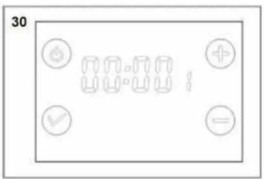
While the first time use or after a long break in the device operation (or a power failure), the current time and day of the week must be programmed.
To enter the time change mode, press the [√] icon and hold it for 5 seconds (Fig. 1). The hour digits will start flashing (Fig. 2)
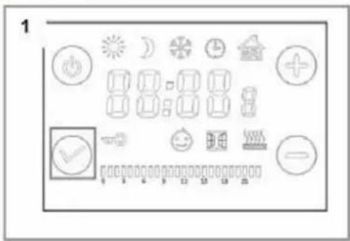
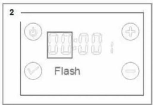
Press [+] and [-] to set the hour (Fig.3), in case of no operation for 30 s, it will move to the minute settings.
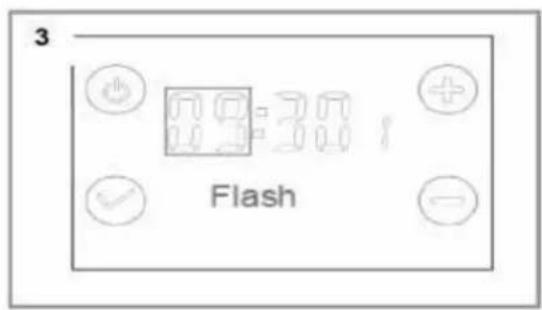
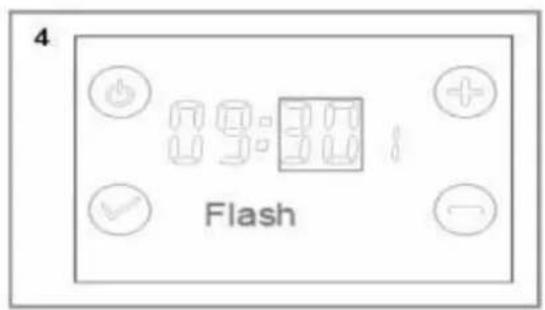
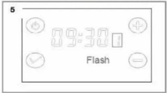
Press the [√] icone. Minute digitals will start to flash. Press [+] and [-] to set minutes (Fig. 4) Press and release the [√] icone until week (1) starts flashing (Fig. 5). Press [+] and [-] to set the current day of the week.
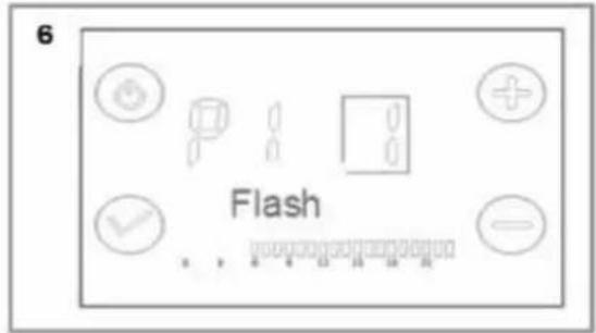
1 = Monday, 2 = Tuesday, 3 = Wednesday, 4 = Thursday, 5 = Friday, 6 = Saturday, 7 = Sunday. After setting, shortly press the [√] icon to enter P mode. If there is no operation for 30 seconds, the setting will go into P mode automatically (Fig. 6).
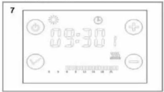
Press shortly [+] or [-] to select the mode. Pressing [+] activates the comfort mode (shown with the marks assigned to a given hour). Pressing [-] activates the economy mode (no marks assigned to the hour on the display). Assign P mode from Monday to Sunday (P1-P7) (Fig. 7).
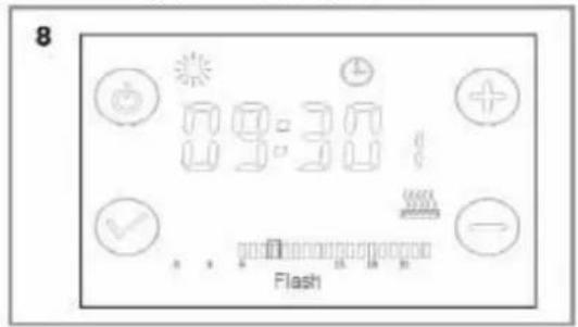
SAMPLE SETTINGS (Fig. 8):

Heating state is on

Comfort mode is on
Current time

Present day is Monday

Timing mode
Example: 6:00-22:00


Current operating position: flashes
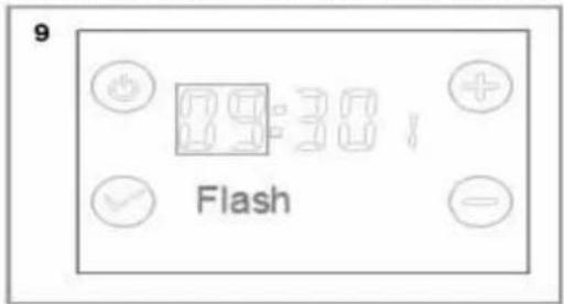
Press and hold the [√] icon for 3 seconds until [09] starts flashing. (Fig. 9)
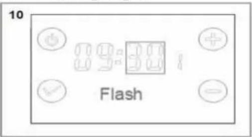
Press the [√] icon briefly until [30] starts flashing. (Fig. 10)
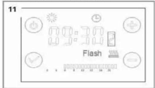
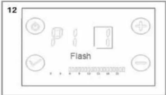
Press [√] icon, [1] will start flashing. Press [+] to set [2] (Tuesday) (Fig. 11). Press the [√] icon to accept and enter the P mode. (Fig. 12)
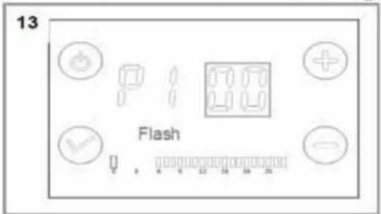
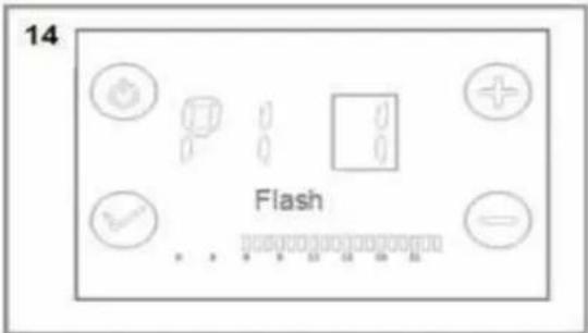
Press and hold [✓] icon for 5 seconds until 1 changes to [00] (Fig. 13). Press [+] and [-] to change P1 mode (press [+] to set comfort mode and [-] to set economy mode). After selecting the required mode, press the [✓] icon to confirm and exit (Fig. 14).
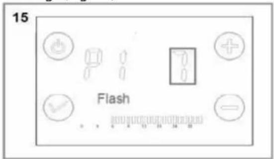
By pressing the [√] icon, you can program other days of the week. 1 is Monday, 2 is Tuesday ... 7 is Sunday (Fig. 15). Press [√] to move to the next days, use the [+] and [-] buttons to select the desired mode and press [√] again to exit. If there is no activity for 30 seconds, the programmer will move to the time settings (Fig. 16).

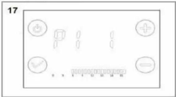
P1 - P7 MODES - SETTING EXAMPLE
P1 mode (Fig. 17): the comfort mode is active between 6:00 - 22:00 (outside these hours, the device works in economy mode.
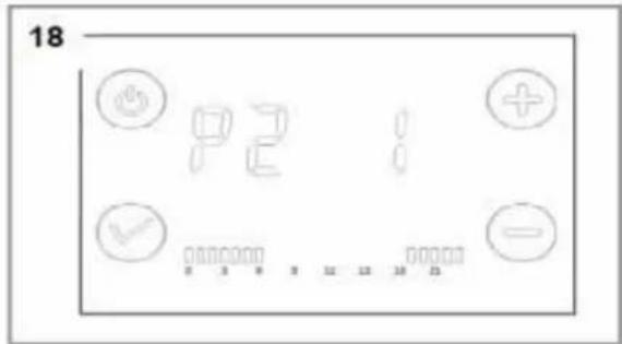
P2 mode (Fig. 18): the comfort mode is active between 19:00 - 6:00 (outside these hours the device works in economy mode.
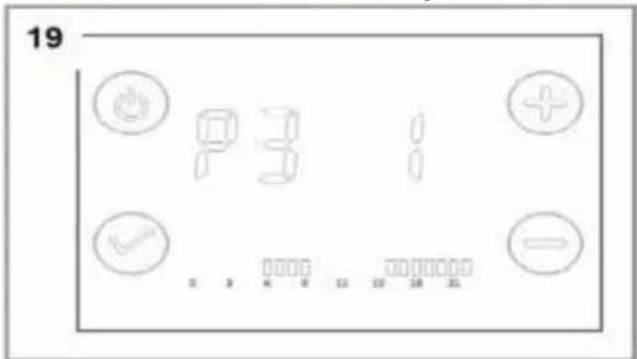
P3 mode (Fig. 19): the comfort mode is active between 6:00 - 9:00 and 16:00 - 22:00 (outside these hours the device works in economy mode).
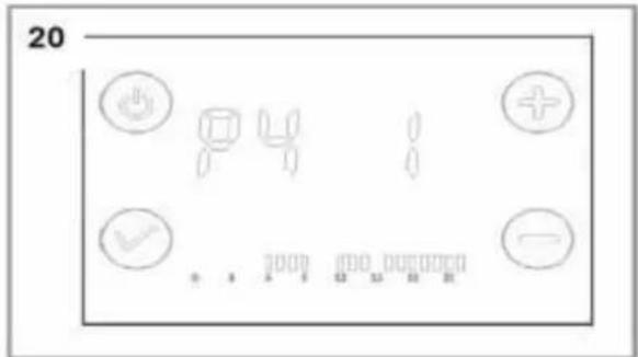
P4 mode (Fig. 20): the comfort mode is active between 6:00 - 9:00, 12:00 - 14:00 and 16:00 - 22:00 (outside these hours the device works in economy mode).
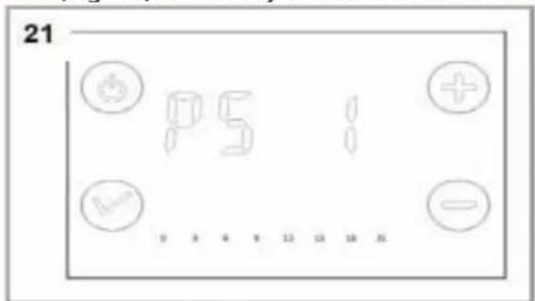
P5 mode (Fig. 21): economy mode is active between 0:00 and 24:00.
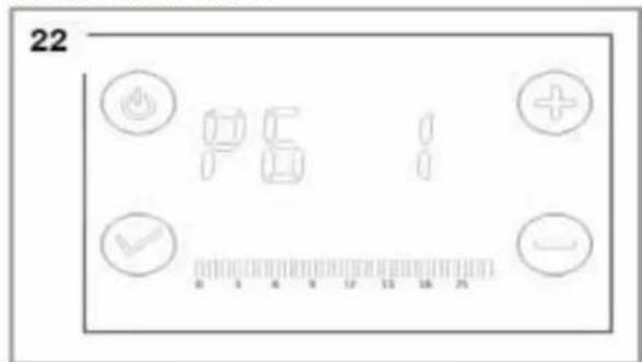
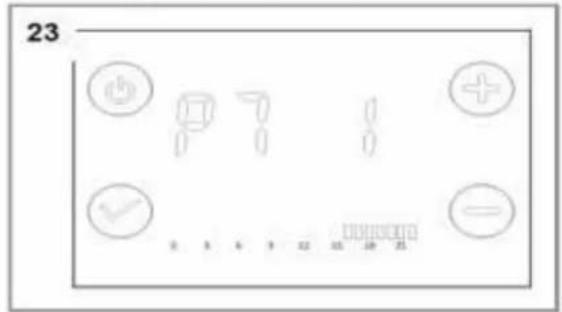
Mode P6 (Fig. 22): Comfort mode is active between 0:00 and 24:00. P7 mode (Fig. 23): the comfort mode is active between 16:00 - 24:00 (outside these hours the device works in economy mode).
CHILD LOCK FUNCTION
To prevent changes to the settings, the user can set a child lock. Press [+] and [-] simultaneously and hold for about 5 seconds until the key icon will appear on the display. The device will be locked in the current operating mode, it is only possible to turn it off using the on / off button. To disable the child lock function, press and hold [+] and [-] again simultaneously for 5 seconds until the key icon turns off.
INTERNAL SETTINGS
To program additional machine functions, press and hold [+] for 5 seconds when the machine is off, then press the [] icon to change mode, and [+] and [-] to make changes.
F0 - Temperature compensation
F1 - Open window function (detection of a sudden drop in temperature in the room)
F2 - Protection against scalding
[0] means the function is inactive when the device is turned off.
TEMPERATURE COMPENSATION
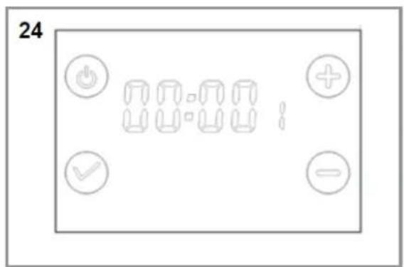
On the stand-by mode, press[+] for 5 s. (Fig. 24)
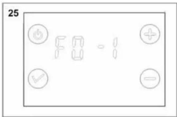
If the temperature is not correct, it must be programmed using the temperature compensation function (Fig. 25). Press [+] while the device is turned off. Temperature can be compensated of +/- 5°C. Briefly press the [√] icon to confirm.
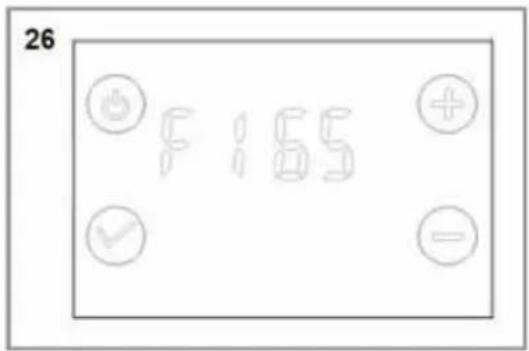
OPEN WINDOW FUNCTION
[0] means that the function is inactive.
This function allows you to detect a sudden drop in room temperature. It comes on when the room temperature drops by 2^ C within 5 minutes while the device is operating. This means opening a window. In this case, when the unit is in frost protection mode, operation is suspended for 65/90 minutes, then the unit returns to the previous operating mode. If the ambient temperature drops again by 2^ C within 5 minutes, the open window detection function will restart and heating will stop again for 65/90 minutes. The device is running in this cycle.
Press [+] to start the open window detection (Fig. 26). You can change the time to resume heating. Select [0], [65] or [90], which is the number of minutes after which the operation of the device will be resumed.
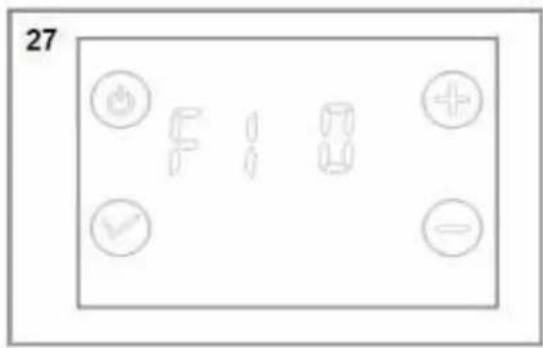
After entering the desired setting, shortly press the [√] icon to enter other settings.
To disable open window function, press [-] and select [0] (Fig. 27)
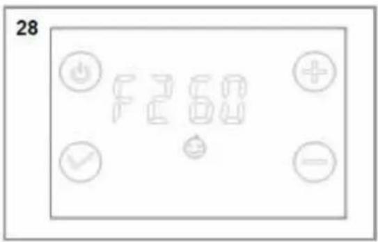
ANTI-SCALD FUNCTION
Press [+] and [-] to adjust the product temperature (Fig. 28): [0], [40], [45], [50], [55], [60] °C. After selecting the desired setting, shortly press the [√] icon to confirm and switch to other modes.
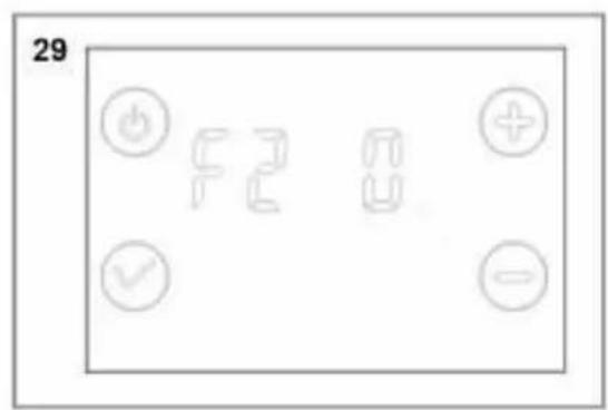
To disable the anti-scalding function, press [-] and select 0, (Fig. 29)
POWER FAILURE MEMORY FUNCTION
In the event of a sudden power failure, the device retains the remembered operating mode and automatically restarts it after reconnecting to the power supply.
However, the time settings must be re-done.
RETURN TO FACTORY SETTINGS
To reset the device settings, hold the on / off button for 10 seconds. Then press the button again. The device will be restored to factory settings. The temperature in the comfort mode will be 19^ , in the economy mode: 15.5^ . The hour will be [0000], the day of the week: [1], P1-P7 will be reset to default settings.
Remote mode
Press [√] switches to remote control mode, this function needs to be installed with the user's home special controller to use with, after successful connection, by the user special control heater, as shown
in the figure.
Remote control mode allows you to receive commands from the central control line, connected to your radiator via the control line (black wire). There are four modes in line control mode 1) comfort mode 2) economy mode 3) defrost mode 4) switch-off mode, where the machine automatically runs according to the input signal mode of the signal line; the display reads: set temperature (comfort 19°C, economy 15°C, antifrost 7°C, no display when stopped), FP signal line control operation mode, heating symbol.
CLEANING AND MAINTENANCE

DANGER! Danger of injury! Before carrying out any work on the device, always disconnect it from the power supply.

ATTENTION! Danger of damaging the device! Do not use strong chemical cleaning agents or solvents for cleaning. The plastic parts of the device may be damaged.
TROUBLE SHOOTING

DANGER! Danger of injury! Incorrectly performed repairs may result in the equipment no longer functioning safely. This poses a threat to the user and his environment.

Some minor disturbances can be removed directly by the user. To avoid additional costs and problems, please check the solutions in the table below before calling qualified service personnel.
| PROBLEM | POSSIBLE CAUSE | SOLUTION |
| Device does not heat. | The device is switched off. | Switch the device on and set the desired level of heat. |
| The set temperature is too low. | Set the higher temperature. | |
| There is no mains voltage. | Check the power cord, plug, socket and fuse. |
If the temperature of the device exceed max programmed temperature, or the temperature sensor has a short circuit, the display shows an error [Er] instead of temperature.
ARRANTYW TERMS
Your device is guaranteed by the manufacturer for a period of 24 months from the date of purchase (Use the dated invoice as proof).
EXCLUSIONS:
The warranty does not cover wear parts of the product, or problems or damage resulting from:
(1) surface damage due to normal product wear
(2) defects or deterioration due to contact of the product with food or liquids and due to corrosion caused by rust
(3) an y incident, abuse, misuse, unauthorized modification, disassembly or repair
(4) improper maintenance, use not in accordance with product instructions, or connection to incorrect voltage
(5) any use of accessories not supplied or approved by the manufacturer.
Information: The warranty will be invalidated if the nameplate and/or the serial number of the product are missing.
REPAIR SERVICES
In the event of a malfunction during the period of the manufacturer's warranty: any request for support must be made to the professional retailer from whom you purchased your product. It is therefore guaranteed for 2 years from the date of purchase. Keep your receipt which will serve as proof of purchase.
In the event of a malfunction, you must return your product to your point of sale.
TECHNICAL CHARACTERISTICS
| Reference(Model) | OCEAISH500W(GD960540E) | OCEAISH750W(EKA-140-54) |
| Nominal power 500W 700W | ||
| IP | IP24 | IP24 |
| Nominal voltage 220-240V~ | ||
| Rated frequency 50-60Hz | ||
| Class II | ||
| Thermostat | 10 programs(4 programs available when using pilot wire) | |
| Model number(s): OCEAISH500W (GD960540E) and OCEAISH750W (EKA-140-54) | ||||||
| Features Symbol Value Unit F Features Status | ||||||
| Thermal power | Type of heat input, for decentralised electric storage heaters only (select one type only) | |||||
| Rated thermal output P | non | OCEAISH500W (GD960540E) : 0.5OCEAISH750W (EKA-140-54) : 0.7 | kW manual | thermal control of the load with integrated thermostat | [no] | |
| heat output Minimum (indicative) | num | NA | kW | manual thermal control of the load with information on room and/or outside temperature | [no] | |
| Maximum continuous thermal power | Pmaxc | OCEAISH500W (GD960540E) : 0.5OCEAISH750W (EKA-140-54) : 0.7 | kW | electronic thermal control of the load with information on room and/or outside temperature | [no] | |
| electricity consumption | Auxiliary | heat output regulated by fan | [no] | |||
| At rated thermal output | model | 0 | kW | Heat output/room temperature control type (select one type only) | ||
| At minimum thermal output | model | 0 | kW | single-stage heat output control, no room temperature control | [no] | |
| In standby mode | sel | 0,000 | kW | control with two or more manual steps, no room temperature control | [no] | |
| room temperature control with mechanical thermostat | [no] | |||||
| electronic control of room temperature | [no] | |||||
| electronic room temperature control and daily timer | [no] | |||||
| electronic room temperature control and weekly timer | [Yes] | |||||
| Other control options (select one or more options) | ||||||
| room temperature control, with presence detector | [no] | |||||
| room temperature control, with open window sensor | [Yes] | |||||
| remote control option | [no] | |||||
| adaptive activation control | [no] | |||||
| limited activation time | [Yes] | |||||
| black globe sensor | [no] | |||||
| Contact details | OCEANIC120-126 quai de Bacalan CS 1158433000 BORDEAUX France | |||||
CARE AND CLEANING
Switch off from the power supply before cleaning.
Using a soft, moist cloth, with or without a mild soap solution, carefully clean the exterior surface of the product.
CAUTION: Allow the product to completely cool before handling or cleaning it.
Do not allow water or other liquids to run into the interior of the product, as this could create a fire and/or electrical hazard.
We also recommend the periodic cleaning of this appliance by lightly running a vacuum cleaner nozzle over the guards to remove any dust or dirt that may have accumulated inside or on the unit.
CAUTION: Do not use harsh detergents, chemical cleaners or solvents as they may damage the surface finish of the plastic components.
ENVIRONMENTAL PROTECTION
This symbol is known as the 'Crossed-out Wheelie Bin Symbol'. When this symbol is marked on a product or battery, it means that it should not be disposed of with your general household waste. Some chemicals contained within electrical/electronic products or batteries can be harmful to health and the environment. Only dispose of
electrical/electronic/battery items in separate collection schemes, which cater for the recovery and recycling of materials contained within. Your co-operation is vital to ensure the success of these schemes and for the protection of the environment.
Instruction manual version: V1
This instruction book is also available on our website:
www.oceanic.eu
Oceanic
120-126 Quai de Bacalan
CS 11584
33000 Bordeaux
IMPORTED BY :
A.M.C.
123, QUAI JULES GUESDE
94400 VITRY SUR SEINE
France
oceanic
natural_image
Pure recycling symbol icons without any text or labels- CONSIGNES DE SÉCURITÉ
- MERCI DE BIEN VQULOIR LIRE LES CONSIGNES DE SECURITÉ ATTENTIVEMENT AVANT D'UTILISER L'APPAREIL. CONSERVEZ-LES POUR TOUTE CONSULTATION ULTERIEURE.
- SCHÉMA D'INSTALLATION
- DANGER!
- MISE EN PLACE DU PRODUIT
- CONDITIONS DE GARANTIE
- INSTALLATION
- RECOMMENDATIONS IMPORTANT READ BEFORE INSTALLATION
- RECOMMENDATIONS FOR WALL MOUNTING
- INSTALLATION IN THE BATHROOM
- ELECTRICAL CONNECTION
- INSTALLATION OF THE DEVICE
- LIST OF PARTS
- PRODUCT INSTALLATION
- DEVICE OPERATION
- CONTROL PANEL BUTTONS
- COMFORT MODE
- ECONOMY MODE
- ANTI FREEZE MODE
- TIMER
- SAMPLE SETTINGS (Fig. 8):
- P1 - P7 MODES - SETTING EXAMPLE
- CHILD LOCK FUNCTION
- INTERNAL SETTINGS
- TEMPERATURE COMPENSATION
- OPEN WINDOW FUNCTION
- ANTI-SCALD FUNCTION
- POWER FAILURE MEMORY FUNCTION
- RETURN TO FACTORY SETTINGS
- Remote mode
- CLEANING AND MAINTENANCE
- TROUBLE SHOOTING
- ARRANTYW TERMS
- EXCLUSIONS:
- REPAIR SERVICES
- CARE AND CLEANING
- ENVIRONMENTAL PROTECTION
- oceanic
Brand : OCEANIC
Model : OCEAISH750W
Category : Tumble dryer