
H2412G - Cooker Wells - Free user manual and instructions
Find the device manual for free H2412G Wells in PDF.
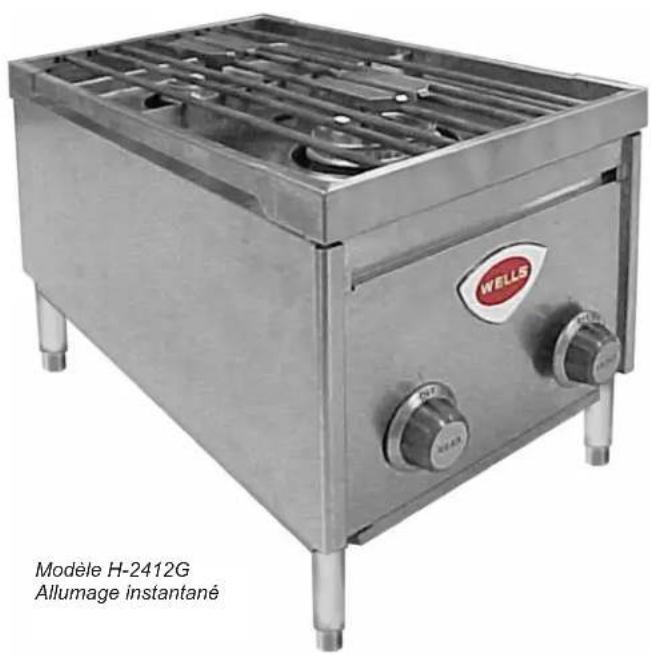
| Product Type | Countertop gas hot plate |
| Brand | Wells |
| Model | H2412G |
| Category | Commercial range |
| Number of Burners | 2 |
| Power per Burner | 12,000 BTU/h |
| Total Power | 24,000 BTU/h |
| Gas Type | Natural gas or propane (depending on configuration) |
| Required Gas Pressure (Natural) | 5 in WC |
| Required Gas Pressure (Propane) | 10 in WC |
| Dimensions (W x D x H) | 11-7/32 in x 22-27/32 in x 4 in (legs included) |
| Weight | Approximately 18 kg (estimated) |
| Material | Stainless steel |
| Ignition | Manual pilot |
| Flame Adjustment | Continuous from OFF to HI |
| Safety Features | Burner actuator, manual gas shut-off |
| Cleaning | Daily, removable parts washable |
| Spare Parts | Burners, grille, drip tray, actuator heads |
| Repairability | By qualified technician only |
| Certifications | NSF, ANSI Z83.11, CSA |
| Usage | Commercial |
Frequently Asked Questions - H2412G Wells
User questions about H2412G Wells
0 question about this device. Answer the ones you know or ask your own.
Ask a new question about this device
Download the instructions for your Cooker in PDF format for free! Find your manual H2412G - Wells and take your electronic device back in hand. On this page are published all the documents necessary for the use of your device. H2412G by Wells.
USER MANUAL H2412G Wells
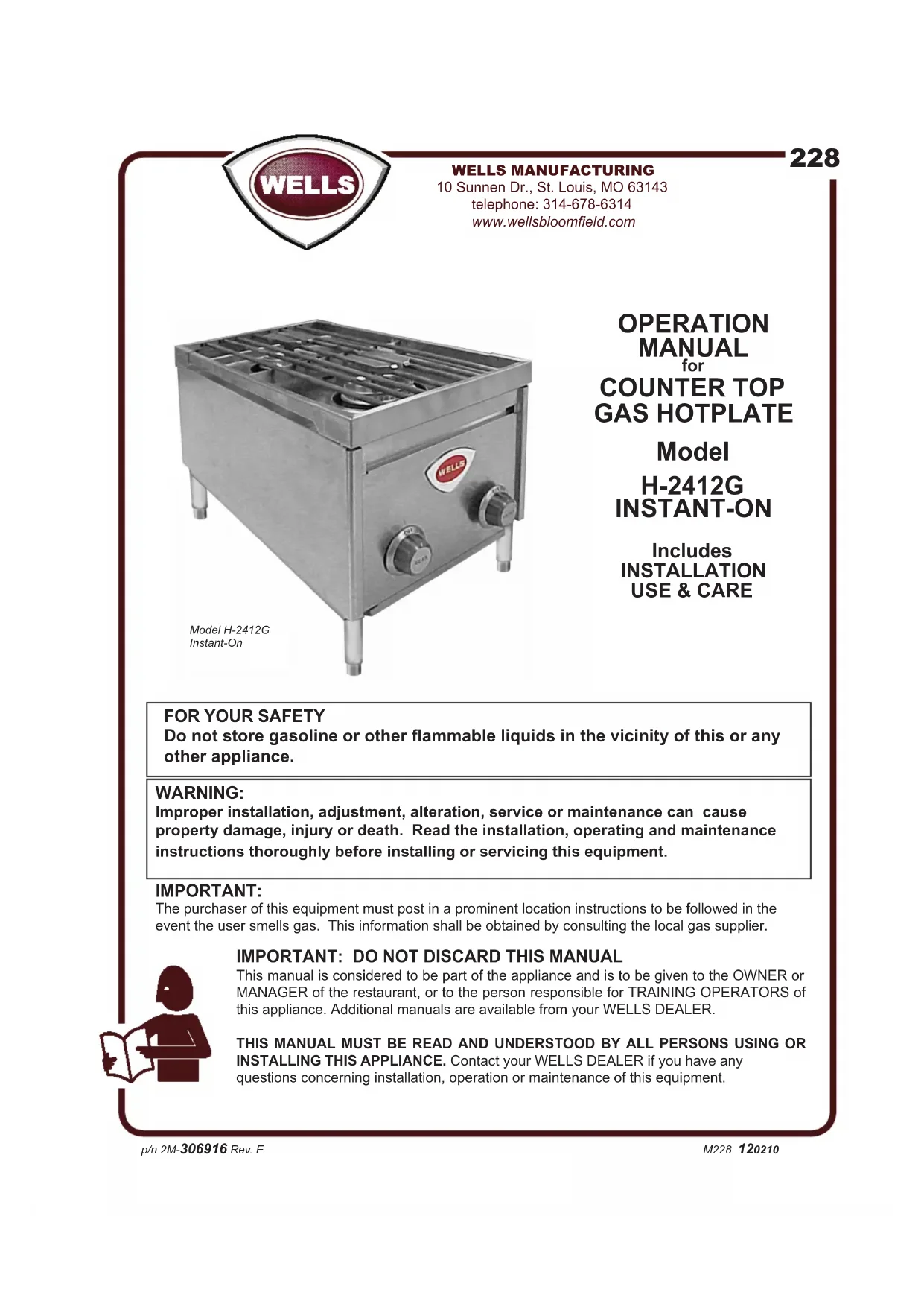
Do not store gasoline or other flammable liquids in the vicinity of this or any other appliance.
WARNING:
Improper installation, adjustment, alteration, service or maintenance can cause property damage, injury or death. Read the installation, operating and maintenance instructions thoroughly before installing or servicing this equipment.
IMPORTANT:
The purchaser of this equipment must post in a prominent location instructions to be followed in the event the user smells gas. This information shall be obtained by consulting the local gas supplier.

IMPORTANT: DO NOT DISCARD THIS MANUAL
This manual is considered to be part of the appliance and is to be given to the OWNER or MANAGER of the restaurant, or to the person responsible for TRAINING OPERATORS of this appliance. Additional manuals are available from your WELL'S DEALER.
THIS MANUAL MUST BE READ AND UNDERSTOOD BY ALL PERSONS USING OR INSTALLING THIS APPLIANCE. Contact your WELL'S DEALER if you have any questions concerning installation, operation or maintenance of this equipment.
LIMITED WARRANTY STATEMENT
Unless otherwise specified, all commercial cooking equipment manufactured by WELLS BLOOMFIELD, LLC is warranted against defects in materials and workmanship for a period of one year from the date of original installation or 18 months from the date of shipment from our factory, whichever comes first, and is for the benefit of the original purchaser only.
THIS WARRANTY IS THE COMPLETE AND ONLY WARRANTY, EXPRESSED OR IMPLIED IN LAW OR IN FACT, INCLUDING BUT NOT LIMITED TO, WARRANTYES OF MERCHANTABILITY OR FITNESS FOR ANY PARTICULAR PURPOSE, AND/OR FOR DIRECT, INDIRECT OR CONSEQUENTIAL DAMAGES IN CONNECTION WITH WELLB S BLOOMFIELD PRODUCTS. This warranty is void if it is determined that, upon inspection by an authorized service agency, the equipment has been modified, misused, misapplied, improperly installed, or damaged in transit or by fire, flood or act of God. It also does not apply if the serial nameplate has been removed, or if service is performed by unauthorized personnel.
The prices charged by Wells Bloomfield for its products are based upon the limitations in this warranty. Seller's obligation under this warranty is limited to the repair of defects without charge by a Wells Bloomfield factory authorized service agency or one of its sub-service agencies. This service will be provided on customer's premises for non-portable models. Portable models (a device with a cord and plug) must be taken or shipped to the closest authorized service agency, transportation charges prepaid, for service. In addition to restrictions contained in this warranty, specific limitations are shown in the Service Policy and Procedure Guide. Wells Bloomfield authorized service agencies are located in principal cities. This warranty is valid in the United States and Canada and void elsewhere. Please consult your classified telephone directory, your foodservice equipment dealer or contact:
Wells Bloomfield, LLC
10 Sunnen Dr., St. Louis MO 63143 USA
phone (314) 678-6314 or fax (314) 781-2714
for information and other details concerning warranty.
SERVICE POLICY AND PROCEDURE GUIDE and ADDITIONAL WARRANTY EXCLUSIONS
- Resetting of safety thermostats, circuit breakers, over load protectors, and/or fuse replacements are not covered by this warranty unless warranted conditions are the cause.
- All problems due to operation at voltages or phase other than specified on equipment nameplates are not covered by this warranty. Conversion to correct voltage and/or phase must be the customer's responsibility.
- All problems due to electrical connections not made in accordance with electrical code requirements and wiring diagrams supplied with the equipment are not covered by this warranty.
- Replacement of items subject to normal wear, to include such items as knobs, light bulbs; and, normal maintenance functions including adjustments of thermostats, adjustment of micro switches and replacement of fuses and indicating lights are not covered by warranty.
- Damage to electrical cords and/or plug due to exposure to excessive heat are not covered by this warranty.
- Full use, care, and maintenance instructions supplied with each machine. Noted maintenance and preventative maintenance items, such as servicing and
cleaning schedules, are customer responsibility. Those miscellaneous adjustments noted are customer responsibility. Proper attention to preventative maintenance and scheduled maintenance procedures will prolong the life of the appliance.
- Travel mileage is limited to sixty (60) miles from an Authorized Service Agency or one of its sub-service agencies.
- All labor shall be performed during regular working hours. Overtime premium will be charged to the buyer.
- All genuine Wells replacement parts are warranted for ninety (90) days from date of purchase on nonwarranty equipment. This parts warranty is limited only to replacement of the defective part(s). Any use of non-genuine Wells parts completely voids any warranty.
- Installation, labor, and job check-outs are not considered warranty and are thus not covered by this warranty.
- Charges incurred by delays, waiting time or operating restrictions that hinder the service technician's ability to perform service are not covered by warranty. This includes institutional and correctional facilities.
SHIPPING DAMAGE CLAIM PROCEDURE
NOTE: For your protection, please note that equipment in this shipment was carefully inspected and packaged by skilled personnel before leaving the factory. Upon acceptance of this shipment, the transportation company assumes full responsibility for its safe delivery.
IF SHIPMENT ARRIVES DAMAGED:
- VISIBLE LOSS OR DAMAGE: Be certain that any visible loss or damage is noted on the freight bill or express receipt, and that the note of loss or damage is signed by the delivery person.
2. FILE CLAIM FOR DAMAGE IMMEDIATELY:
Regardless of the extent of the damage.
- CONCEALED LOSS OR DAMAGE: if damage is unnoticed until the merchandise is unpacked, notify the transportation company or carrier immediately, and file "CONCEALED DAMAGE" claim with them. This should be done within fifteen (15) days from the date the delivery was made to you. Be sure to retain the container for inspection.
Wells Bloomfield cannot assume liability for damage or loss incurred in transit. We will, however, at your request, supply you with the necessary documents to support your claim.
TABLE OF CONTENTS
WARRANTY xi
SPECIFICATIONS 1
FEATURES & OPERATING CONTROLS 2
PRECAUTIONS & GENERAL INFORMATION 3
AGENCY APPROVAL INFORMATION 3
INSTALLATION 4
INITIAL ADJUSTMENT 7
OPERATION 8
TROUBLESHOOTING
CLEANING INSTRUCTIONS 11
ASSEMBLY DIAGRAM 12
PARTS & SERVICE 13
CUSTOMER SERVICE DATA 13
Thank You for purchasing this Wells Bloomfield appliance.
Proper installation, professional operation and consistent maintenance of this equipment will ensure that it gives you the very best performance and a long, economical service life.
This manual contains the information needed to properly install this equipment, and to use and care for the equipment in a manner which will ensure its optimum performance.
SPECIFICATIONS
| MODEL | COOKING SURFACE | STYLE FUEL | MANIFOLD PRESSURE | B.T.U /HR/ BURNER | TOTAL B.T.U./HR | |
| H-2412G Instant-On Dual Pilot | 11-7/32" Wide, 22-27/32" Deep | 2 BURNERS WITH INDIVIDUAL CONTROL | Natural Gas | 5.0" W.C. 12 | 000 24,000 | |
| Propane | 10.0" W.C. | 12,000 24,000 |
FEATURES & OPERATING CONTROLS
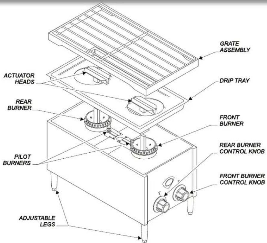
Fig. 1 Countertop Gas Hotplate - Features & Operating Controls
BURNERS Provide cooking heat
Front and rear burners are individually controllable
Removable for easy cleaning
BURNER CONTROL Provide individual control of front and rear burners
KNOBS
PILOT LIGHT Provides ignition source for main burners
ACTUATOR Admits gas to burner when depressed. Actuator head removable for easy cleaning
GRATE ASSEMBLY Holds food product at proper distance from burner flame. Removable for easy cleaning
DRIP TRAY Catches drippings Removable for easy cleaning
ADJUSTABLE LEGS Allow for ventilation under hotplate. Provide means of leveling the appliance, and of cleaning underneath
NAMEPLATE Gives Manufacturer, Model and Serial Number (on back—not shown) Also provides fuel specifications and agency approval information
PRECAUTIONS AND GENERAL INFORMATION
This appliance is intended for use in commercial establishments only.
This appliance is intended to prepare food for human consumption. No other use is recommended or authorized by the manufacturer or its agents.
This hotplate must be installed by a technician qualified and certified or licensed to install gas-fired equipment. A licensed technician must perform the initial startup and adjustment of this appliance.
Operators of this appliance must be familiar with the appliance use, limitations and associated restrictions. Operating instructions must be read and understood by all persons using or installing this appliance.
Cleanliness of this appliance is essential to good sanitation. Read and follow all included cleaning instructions and schedules to ensure the safety of the food product.
DO NOT submerge hotplate or burners in water. DO NOT splash or pour water into interior of hotplate. Burners which have been allowed to become wet must be thoroughly dried before use.
Hotplate must be operated with supplied 4" legs properly installed.
The technical content of this manual, including any parts breakdown illustrations and/or adjustment procedures, is intended for use by qualified technical personnel only.
Any procedure which requires the use of tools must be performed by a qualified technician.
This manual is considered to be a permanent part of the appliance. This manual and all supplied instructions, diagrams, schematics, parts breakdown illustrations, notices and labels must remain with the appliance if it is sold or moved to another location.
This appliance is made in the USA. Unless otherwise noted, this appliance has American sizes on all hardware.
AGENCY APPROVAL INFORMATION
This unit complies with NSF standard 4 only if maintained and operated per the instructions in this manual.
This appliance meets ANSI Z83.11 specifications for gas-fired food service equipment.
This appliance is CSA listed for gas operation.

STD4

US
INSTALLATION
NOTE: DO NOT discard the carton or other packing materials until you have inspected the appliance for hidden damage and tested it for proper operation. Refer to SHIPPING DAMAGE CLAIM PROCEDURE on the inside front cover of this manual.

DANGER: HEALTH HAZARD
This appliance must be properly ventilated. Failure to provide proper ventilation of exhaust gasses can result in severe injury and death.

WARNING: FIRE HAZARD
Do not store flammable or combustible materials near this appliance. The open flame of this appliance can cause such materials to ignite.
NOTICE:
Manufacturer's warranty on this hotplate is in effect only when the hotplate is installed and operated in accordance with these instructions and local codes and ordinances or, in the absence of local codes, the National Fuel Gas Code, ANSI Z223.1 (current edition). The manufacturer of the hotplate assumes no liability for any damage resulting from failure to comply with this notice.
UNPACKING & INSPECTION
Carefully remove the hotplate from the carton. Remove all protective plastic film, packing materials and accessories from the hotplate before connecting the hotplate to fuel gas or otherwise performing any installation procedure.
Carefully read all instructions in this manual and the Installation Instruction Sheet packed with the hotplate before starting any installation.
Read and understand all labels and diagrams attached to the hotplate.
Carefully account for all components and accessories before discarding packing materials. Store all accessories in a convenient place for later use.
Thoroughly clean the appliance before use. See Cleaning Instructions, page 11.
SETUP
Setup the hotplate only on a firm, level, non-combustible surface. The hotplate must be leveled with a spirit level in its final operational position, prior to beginning the gas piping installation.
Clearances to adjacent surfaces must be maintained.
Maintain a minimum of 3 from hotplate sides and 3 from rear of the hotplate to combustible walls; 0 from sides and rear of the hotplate to non-combustible walls; and; 4 from non-combustible counter as established by provided 4 legs. Supplied legs must be properly installed. Once installed, the legs should NOT be removed.
Maintain adequate clearances for cleaning and proper operation.
The hotplate must be installed in an area with sufficient make-up air for proper combustion, and must be installed such that the flow of combustion and ventilation air will not be obstructed.
For servicing, Wells Mfg. recommends 6'' clearance from rear of the hotplate to wall.
When used with an exhaust fan, special precautions must be observed to avoid interference with the operation of the hotplate, such as drafts and air starvation.
The current edition of NFPA 96 (Standard for the Installation of Equipment for the Removal of Smoke and Grease Laden Vapors from Commercial Cooking Equipment) specifies ventilation requirements to ensure the removal of exhaust gasses and products of combustion. IT IS THE RESPONSIBILITY OF THE INSTALLER TO ENSURE THAT THIS GAS HOTPLATE INSTALLATION CONFORMS TO ALL APPLICABLE CODES AND ORDINANCES.
The area where the hotplate is installed must be kept clear of combustibles and flammables. This includes mops, rags, grease, wrapping paper and electric cords.
INSTALLATION (continued)
The installation of gas piping from the outlet side of the gas meter or service regulator to the hotplate must be performed by a technician qualified and certified or licensed to install gas-fired equipment.
A licensed and qualified technician must perform the initial startup and adjustment of this appliance.
The installation of this gas-fired appliance must conform to local codes, or in the absence of such codes, with the current edition of National Fuel Gas Code ANSI Z223.1.
For use in the State of Massachusetts, this appliance must be installed in compliance with Massachusetts Fuel Gas and Plumbing Code CMR 248.
The installation of this gas-fired appliance must comply with applicable portions of NFPA 96 for ventilation.
The venting of this appliance must not be obstructed, nor may such venting interfere with the flow of combustion air required for proper operation of the gas burners.
Additionally:
- The gas supply line used to connect the hotplate to the gas supply system must be black iron pipe, or other material as approved by local ordinance for gas piping.
- Gas supply piping must be inside 3/8 diameter or greater.
- Use pipe sealant made specifically for gas piping on all pipe joints. Apply sealant sparingly to the male threads only. Sealant must be resistant to the action of LP gas.
- Verify that all supply piping is clean and free of obstructions, dirt, chips and pipe sealant compound prior to installation.
- All pipe joints must be checked for leaks before lighting. Leak checks should be performed with a soap and water solution. NEVER CHECK FOR LEAKS WITH AN OPEN FLAME.

DANGER:
FIRE AND
EXPLOSION HAZARD
NEVER use an open flame to check for gas leaks. Fire and explosion may result.
IMPORTANT:
All pipe joints must be checked for leaks before lighting. Leak checks should be performed with a soap and water solution.
IMPORTANT:
Information on the construction and installation of ventilating hoods may be obtained from the current edition of NFPA 96 Standard for the Installation of Equipment for the Removal of Smoke and Grease Laden Vapors from Commercial Cooking Equipment. Copies of this standard are available from the Nation Fire Protection Assn.:
NFPA
1 Batterymarch Park
P.O.Box 9101
Quincy, MA 02269-9101
INSTALLATION (continued)

DANGER:
FIRE AND EXPLOSION HAZARD
NEVER use an open flame to check for gas leaks. Fire and explosion may result.
IMPORTANT:
All pipe joints must be checked for leaks before lighting. Leak checks should be performed with a soap and water solution.

WARNING:
FIRE HAZARD
This hotplate is supplied with a gas pressure regulator. Failure to properly install the supplied regulator will result in an extremely hazardous condition.
Flow arrow stamped on body of regulator must point toward the hotplate.
Regulator adjusting screw and vent hole must point UP.
IMPORTANT:
Verify fuel gas type. If the available fuel does not match the nameplate specification, exchange the hotplate for the correct type. DO NOT attempt to modify a unit in the field to accept a different fuel.
IMPORTANT:
Avoid damage to the regulator: if the gas supply piping system is pressure tested at pressures exceeding 1/2 psig (3.45kPa), the hotplate must be isolated or disconnected from the gas piping system for the duration of the test.
INSTALLING THE HOTPLATE
Refer to the nameplate. Verify the fuel type and pressure, which must match the nameplate specifications. Connecting the hotplate to the wrong fuel type and/or pressure will compromise the safety and/or performance of the appliance.
The hotplate must be placed in its final operational position and leveled front-to-back and side-to-side, with a spirit level, prior to beginning the gas piping installation. Re-check the level of the unit at the conclusion of the gas piping installation.
Each gas hotplate is supplied with a separate gas pressure regulator, which must be installed on the manifold pipe protruding from the rear of the hotplate. Ensure that the regulator is installed such that the flow arrow stamped on the body of the regulator points toward the hotplate. Failure to properly install the supplied regulator will result in an extremely hazardous condition.
A moisture trap (drip leg) consisting of a tee, 4" nipple pointing down, and cap must be installed upstream of the gas pressure regulator.
A manual gas shut-off valve may be required by local codes and is, in any case, strongly recommended. The shut-off valve must be installed between the gas supply piping and the gas pressure regulator.
It is the responsibility of the gas piping installer to identify the code requirement for a shut-off valve.
Shut-off valves, moisture trap and all associated piping must be supplied by the gas piping installer.
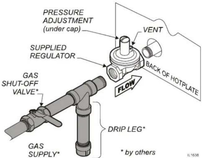
Fig. 2 Gas Supply Piping
INITIAL ADJUSTMENT
SET GAS PRESSURE:
Turn the gas shut-off valve OFF.
A gas pressure test tap is provided on the gas supply manifold. Remove both burner control knobs and the front panel. Remove plug in gas pressure test tap and attach a manometer.
Turn the shut-off valve ON. Light the pilot light and turn both gas control valves to HI. Depress both actuator heads.
Remove the cap from the pressure regulator. Turn the adjusting screw clockwise to increase pressure; counter-clockwise to decrease pressure. Adjust the gas pressure regulator for:
5" water column (natural gas); or, 10 water column (propane).
When finished, replace cap on regulator, turn shut-off valve OFF, remove manometer and reinstall plug in tap. Reassemble hotplate, turn shut-off valve back ON and relight pilot light.
SETPILOTFLAMES:
Remove left side (rear burner) control knob by pulling straight off. Pilot flame adjustment screw is located to the right side of the burner control valve.
Using a small, flat-blade screwdriver, turn the screw clockwise to decrease the flame size, or counter-clockwise to increase the flame size.
Burner should light quickly and completely when burner actuator is depressed. Adjust pilot flame to 1/4" high. Drafty conditions may require a higher flame to allow pilot flame to remain lit.
Reinstall the control knob.
ADJUST BURNER FLAME:

CAUTION: BURN HAZARD
Wear heat protective gloves. Avoid contact with flame.
Remove grate, drip tray and actuator heads. Turn both burner control knobs full on. Adjust one burner at a time.
Loosen locking screw on a burner assembly shutter. Using a metal implement such as a long-handle ladle, press the actuator to light burner.
Turn shutter to admit more or less air as required. Adjust air shutter until flame is mostly blue in color.
Tighten locking screw. Reassemble hotplate when finished.
IMPORTANT:
Pressure adjustment must be performed by a qualified technician only.
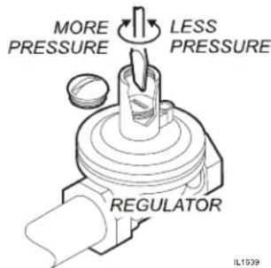
Fig. 3 Gas Pressure Adjustment
IMPORTANT:
Flame adjustment must be performed by a qualified technician only.
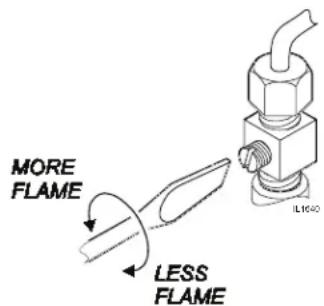
Fig. 4 Pilot Flame Adjustment
NOTE:
The right knob controls the front burner; the left knob controls the rear burner.
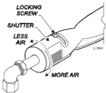
Fig. 5 Burner Flame Adjustment
OPERATION
WARNING
WARNING: FIRE HAZARD
IF YOU SMELL GAS:
DO NOT try to light any appliance.
DO NOT touch any electrical switch
DO NOT use any telephone in your building.
IF YOU SMELL GAS:
Shut down the unit at the main gas shutoff valve and contact your local gas supplier from a neighboring location.
Follow the instructions received from the gas supplier immediately and exactly.

CAUTION:
BURN HAZARD
DO NOT press either actuator by hand. The burner will light anytime the plunger is pressed.
GENERAL OPERATIONAL NOTES
Carefully read the description of the hotplate operation on the specification sheet.
Do NOT use this appliance if it has been submerged in water.
Call a qualified technician to examine the appliance and to service or replace any component which has been submerged. Burners which have been allowed to become wet must be thoroughly dried before use.
For initial startup, and any time the gas supply has been shut-off, it may take several minutes to light the pilot as air in the piping and manifolds is purged.
The burner control knobs must be turned by hand only. Never use tools to turn the control knob. If the knob will not turn by hand, do NOT attempt to force or repair it. Contact your Authorized Wells
Service Agency for repairs. Forced or improperly repaired valves pose the risk of fire and/or explosion.
Make sure burners, pilot burner, drip tray, actuators and grate assembly are properly installed before attempting to operate.
LIGHTING THE PILOT FLAMES
Before lighting the pilot light, smell all around the appliance area for gas. Be sure to smell near floor level because some gas is heavier than air and will settle to the floor.
For initial startup, and any time the gas supply has been shut-off, it may take several minutes to light the pilot as air in the piping and manifolds is purged.
The pilot flame must be lighted by hand:
Turn both control knobs to the full OFF position.
Be sure the gas shut-off valve is ON and the appliance has had time for the air to be purged from the lines.
Remove the grate and drip pan. The pilots are located adjacent to their respective burner.
Light the pilot with a long match or fireplace lighter.
Use of a cigarette lighter is NOT recommended.
IF THE UNIT DOES NOT LIGHT or IN THE EVENT OF A GAS INTERRUPTION:
Turn main valve to unit. Wait 5 minutes for gas to clear.
Turn off all knobs and pilot valves.
Turn on main valve and light pilots.
Turn burner knobs to desired setting. Depress actuator to light burner.
SHUT DOWN INSTRUCTIONS
Turn all burner knobs to OFF.
Turn all pilots OFF.
Turn the main gas supply OFF.
| WARNING: FIRE HAZARD Turn control valves OFF when hotplate is not in use. Failure to turn valves off will allow unattended burner to light should actuator be depressed. |
| WARNING: FIRE AND EXPLOSION HAZARD DO NOT set anything on grate other than cookware to be heated. Pilot flame may be extinguished if blocked. Anything placed on the burners will open the gas valves, which can cause a fire or explosion. |
| OPERATION Inspect the unit for cleanliness before use. Clean as necessary: See Cleaning Instructions, page 11. Be sure the pilot light is lit before operation. See Lighting the Pilot Light, page 8. The burner control knobs must be turned by hand only. Never use tools to turn the control knob. The control used in this gas hotplate provides a continuous range of settings from OFF to HI. The right knob controls the front burner The left knob controls the rear burner Light burner by turning control knob to the HI position. Place cookware on burner to depress the burner actuator. Fire will form in a complete ring around the burner. Set the control knob to the desired heat level. The setting can be readjusted at any time. |
| OFF REAR OFF ON Position HI FRONT IL1642 图.6 Temperature Control The burner flame will automatically extinguish when cookware is removed and the actuator is no longer depressed. |
TROUBLESHOOTING
| SYMPTOM POSSIBLE | CAUSE SUGGESTED REMEDY | |
| Pilot will not light | Gas supply off Check main / unit gas valves | |
| Air in lines Turn gas valve on. Attempt to light pilot every 15 sec. | ||
| Pilot valve not on Turn pilot valve on / adjust | ||
| Pilot burner holes are plugged Clean pilot burner | ||
| Front or rear burner won't light | Actuator not depressed Burner should light only when a pot or pan depresses actuator. Be sure actuator is properly assembled to arm | |
| Pilot flame not lit Turn off gas — allow unit to vent for 5 minutes. Tum gas back on and light both pilots | ||
| Control not on Turn temperature control to HI, Set to desired setting when lit | ||
| Water in burner Remove burner and dry thoroughly | ||
| Damaged temperature control valve, burner, actuator valve or other internal component | Contact Authorized Wells Service Agency for repairs | |
| Burner not hot enough | Control valve not set Adjust for desired temperature | |
| Shutter or nozzle out of adjustment Contact qualified technician for adjustment | ||
| Damaged temperature control valve, burner actuator or other internal component | Contact Authorized Wells Service Agency for repairs |
NOTE: There are no user serviceable components in the burner assemblies or in the control valves. In all cases of damage or malfunction, contact your Authorized Wells Service Agency for repairs.
| CLEANING INSTRUCTIONS | |
| PREPARATION Turn gas shut-off valve OFF before cleaning. Allow hotplate to cool completely before cleaning. FREQUENCY: Daily | WARNING: FIRE HAZARD Shut off the gas supply valve before cleaning. |
| TOOLS Bristle Brush Clean Cloth or Sponge Mild Detergent Cleaner Formulated for Stainless Steel Warm Water | CAUTION: BURN HAZARD Allow hotplate to cool completely before cleaning. |
| CLEANING Turn gas shut-off valve OFF before cleaning. Allow hotplate to cool completely before cleaning. Remove grate and drip tray by lifting from cabinet. Slide actuator heads off actuator arms. Note position of front and rear burner assemblies in cabinet. Remove burner assemblies. Clean food particles from grate, actuator heads, drip tray and crumb tray with warm water, mild detergent and a bristle brush. Rinse with clean water. Wipe dry with a soft clean cloth. Examine burner assemblies. Note position of air shutters before cleaning. Clean food particles from burners with warm water, mild detergent and a bristle brush. Rinse by wiping with a soft cloth dampened with clean water. Wipe exterior surfaces dry with a soft clean cloth. Allow burners to air dry so that interior passages are completely free of water. Wipe the outer portions of the hotplate cabinet with a clean soft cloth or sponge dampened with warm water and a mild detergent or cleaner formulated for cleaning stainless steel. DO NOT use steel wool to clean hotplate cabinet. Rinse by wiping hotplate cabinet with a clean soft cloth or sponge moistened with clean warm water. Dry cabinet by wiping with a clean soft dry cloth. Examine burners to be sure the air shutters are in their proper position. Reinstall burner assemblies in cabinet (see fig. 7, page 12): Burner with short venturi is the REAR burner. Venturi / air shutter slides over left nozzle. Fingers on burner bracket slide into rear notches in center brace. Burner with long venturi is the FRONT burner. Venturi / air shutter slides over right nozzle. Fingers on burner bracket slide into front notches in center brace. Turn shut-off valve ON and light pilot flame. Reinstall drip tray, actuator heads and grate. Procedure is complete. | IMPORTANT: DO NOT spill or pour water into controls, DO NOT submerge hotplate cabinet in water. Damage to internal components will occur. Damage to internal components from water damage is NOT covered by warranty. DO NOT steel wool or metal scouring pads to clean cabinet, drip tray or crumb tray. Good sanitation is vital to the quality of the final food product. Be sure to clean in all corners and crevices where grease and other cooking debris can accumulate. |
CLEANING INSTRUCTIONS (continued)
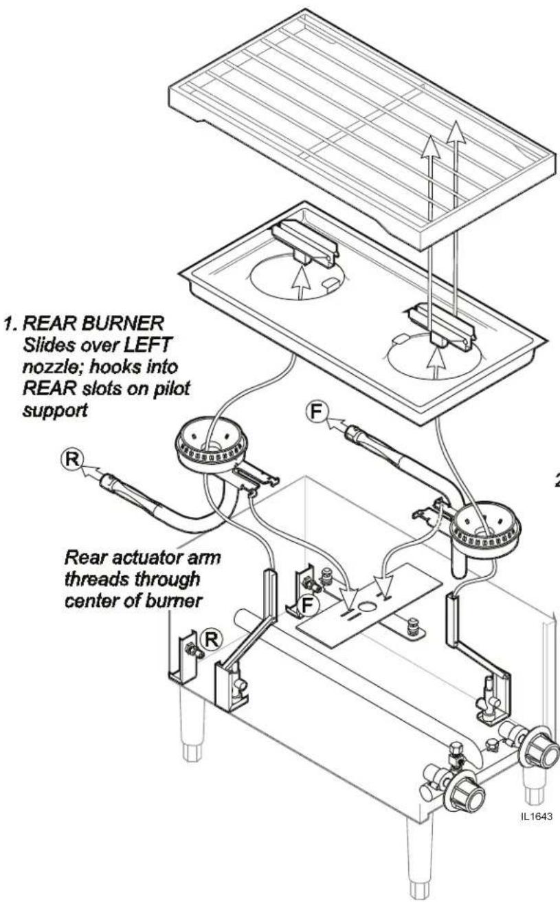
Fig. 7 Hotplate Assembly
- GRATE ASSEMBLY
Sets in place above burners
Actuator heads wrap around center bar of grate
3.DRIP TRAY
Drops in place exposing tops of burners
Actuator heads slide onto ends of actuator arms
2.FRONT BURNER
Slides over RIGHT nozzle; hooks into FRONT slots on pilot support
Front actuator arm threads through center of burner

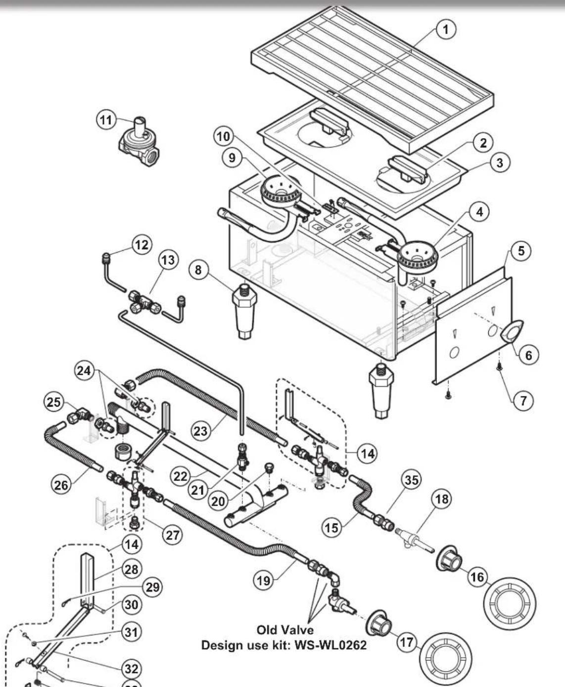
EXPLODED VIEW: H-2412G GAS HOTPLATE

IL1812 Rev. D 11/15/11
Model: H-2412GIO
COUNTERTOP GAS HOTPLATE
PL228
| H-2412G COUNTERTOP GAS HOTPLATE | ||
| Fig No Part No. Description | ||
| 1 WS-506707 GRATE ASSY H241 | 2G LAVISTA | |
| 2 I7-306331 ACTUATOR HEAD (REMOVABLE) | ||
| 3 I7-306706 PAN TOP ASSY (DRIP PAN) | ||
| 4 2F-306905 BURNER FRONT H24 | 412G | |
| 5 I7-39322 PANEL FR H2412G | ||
| 6 2M-300534 TRADEMARK DOME | D LABEL | |
| 7 2C-33935 SCREW 6ABX5/16 PH | PAN SMS | |
| 8 2R-Y5092 BLK PLSTC LG, 4", 1-3/8 ADJ | ||
| 9 2F-306906 BURNER REAR H24 | 2G | |
| 10 2C-39319 CLIP HORSESHOE (2 REQ) | ||
| 11 | 2J-39007 REGULATOR FRESSURE GAS | |
| 2J-39284 REGULATOR GAS LP | ||
| 12 2J-306342 PILOT ASSY 3/16 TUBE | ||
| 13 2K-306350 TEE | BRS 3/16CCX3/16CCX3/16 | |
| 14 WS-506860 KIT SERV H2412G | ACTUATOR | |
| 15 M3-506919 TUBE SS 1/40 X 4 F | LEX FR | |
| 16 2R-39325 KNOB CONTROL AS | SY FRONT | |
| 17 2R-39327 KNOB CONTROL AS | SY REAR | |
| 18 | WS-WL0262 | MANUAL VALVE REPLACEMENT KIT |
| 2V-Z15185 | VALVE MANUAL GAS HOTPLATE | |
| 19 M3-506917 TUBE SS 1/4D X 16 | FLEX FR | |
| 20 2P-39245 PLUG HEX HEAD 1/8 NPT BRA | ||
| 21 2K-39315 FTG PILOT ADJ 3/16 TUBE | ||
| 22 2K-39313 MAN FOLD PIPT H2412G | ||
| 23 1L-306920 TUBE SS 1/4DX17 FLEX REAR | ||
| 24 | 2A-39335 | ORIFICE HOOD #53, NAT |
| 2A-39338 | ORIFICE HOOD #60, LP | |
| 25 2K-306349 ELBOW ORIFICE 1/4CC X 3/8 | ||
| 26 1L-306918 TUBE SS 1/4D X 5.5 FLEX | ||
| 27 2V-306352 VALVE SHUTOFF H2412GINSTA | ||
| 28 17-306333 ARM PIVOT H2412G | ||
| 29 2C-305361 PIN COTTER HAIRPIN 1-3/16 | ||
| 30 2C-306344 PIN CLEVIS 7/8 X .182DIA | ||
| 31 2C-35455 NUT 8-32 HEX MS SS | ||
| 32 17-306332 ARM ACTUATOR AS | ||
| 33 2C-306343 PIN CLEVIS 1 1/2 X .182 DIA | ||
| 34 2P-306346 SPRING TORSION | ||
| 35 2K-Z 15186 FEMALE FITTING, 25CC X 3/8-27UNS | ||
NOTE:
PARTS & SERVICE
DESCRIPTION
SERVICE
PART
IMPORTANT: Use only
Nctory authorized service parts and replacement filters.
LEGS, PLASTIC 4" 2R-Y5092
DRIP TRAY, DUAL PILOT HOTPLATE 17-306706
GRATE, STAINLESS STEEL I7-306707
For factory authorized service, or to order factory authorized replacement parts, contact your Wells authorized service agency, or call:
Wells Bloomfield, LLC
10 Sunnen Drive
St. Louis, MO 63143
Service Parts Dept.
phone: (314) 678-6314
fax: (314) 781-2714
Service Parts Department can supply you with the name and telephone number of the WELLS AUTHORIZATION SERVICE AGENCY nearest you.
CUSTOMER SERVICE DATA
please have this information available if calling for service
RESTAURANT LOCATION
INSTALLATION DATE TECHNICIAN
SERVICE COMPANY
ADDRESS STATE ZIP
TELEPHONE NUMBER ( ) - EQUIPMENT MODEL NO.
EQUIPMENT SERIAL NO.
FUEL: (check one) Natural Gas LP / Propane

Wells Bloomfield proudly supports CFESA Commercial Food Equipment Service Association
SERVICE TRAINING - QUALITY SERVICE

Genuine PartsProtect - YOU - All - Ways

CUSTOMER SATISFACTION

WELLS MANUFACTURING
10 Sunnen Dr., St. Louis, MO 63143
telephone: 314-678-6314
fax: 314-781-2714
www.wellsbloomfield.com

WELLS MANUFACTURING
10 Sunnen Dr., St. Louis, MO 63143
telephone: 314-678-6314
www.wellsbloomfield.com
228
MANUEL D'UTILISATION pour PLAQUE HAUFFANTE DE OMPTOIR A GAZ
Modèle
H-2412G
ALLUMAGE
INSTANTANÉ
Contenu INSTALLATION, UTILISATION ET ENTRETIEN
POUR VOTRE SECURITE
Unless otherwise specified, all commercial cooking equipment manufactured by WELLS BLOOMFIELD, LLC is warranted against defects in materials and workmanship for a period of one year from the date of original installation or 18 months from the date of shipment from our factory, whichever comes first, and is for the benefit of the original purchaser only.
THIS WARRANTY IS THE COMPLETE AND ONLY WARRANTY, EXPRESSED OR IMPLIED IN LAW OR IN FACT, INCLUDING BUT NOT LIMITED TO, WARRANTYES OF MERCHANTABILITY OR FITNESS FOR ANY PARTICULAR PURPOSE, AND/OR FOR DIRECT, INDIRECT OR CONSEQUENTIAL DAMAGES IN CONNECTION WITH WELLB S BLOOMFIELD PRODUCTS. This warranty is void if it is determined that, upon inspection by an authorized service agency, the equipment has been modified, misused, misapplied, improperly installed, or damaged in transit or by fire, flood or act of God. It also does not apply if the serial nameplate has been removed, or if service is performed by unauthorized personnel.
The prices charged by Wells Bloomfield for its products are based upon the limitations in this warranty. Seller's obligation under this warranty is limited to the repair of defects without charge by a Wells Bloomfield factory authorized service agency or one of its sub-service agencies. This service will be provided on customer's premises for non-portable models. Portable models (a device with a cord and plug) must be taken or shipped to the closest authorized service agency, transportation charges prepaid, for service. In addition to restrictions contained in this warranty, specific limitations are shown in the Service Policy and Procedure Guide. Wells Bloomfield authorized service agencies are located in principal cities. This warranty is valid in the United States and Canada and void elsewhere. Please consult your classified telephone directory, your foodservice equipment dealer or contact:
Wells Bloomfield, LLC
10 Sunnen Dr., St. Louis MO 63143 USA
phone (314) 678-6314 or fax (314) 781-2714
for information and other details concerning warranty.
SERVICE POLICY AND PROCEDURE GUIDE and ADDITIONAL WARRANTY EXCLUSIONS
- Resetting of safety thermostats, circuit breakers, over load protectors, and/or fuse replacements are not covered by this warranty unless warranted conditions are the cause.
- All problems due to operation at voltages or phase other than specified on equipment nameplates are not covered by this warranty. Conversion to correct voltage and/or phase must be the customer's responsibility.
- All problems due to electrical connections not made in accordance with electrical code requirements and wiring diagrams supplied with the equipment are not covered by this warranty.
- Replacement of items subject to normal wear, to include such items as knobs, light bulbs; and, normal maintenance functions including adjustments of thermostats, adjustment of micro switches and replacement of fuses and indicating lights are not covered by warranty.
- Damage to electrical cords and/or plug due to exposure to excessive heat are not covered by this warranty.
- Full use, care, and maintenance instructions supplied with each machine. Noted maintenance and preventative maintenance items, such as servicing and
cleaning schedules, are customer responsibility. Those miscellaneous adjustments noted are customer responsibility. Proper attention to preventative maintenance and scheduled maintenance procedures will prolong the life of the appliance.
- Travel mileage is limited to sixty (60) miles from an Authorized Service Agency or one of its sub-service agencies.
- All labor shall be performed during regular working hours. Overtime premium will be charged to the buyer.
- All genuine Wells replacement parts are warranted for ninety (90) days from date of purchase on nonwarranty equipment. This parts warranty is limited only to replacement of the defective part(s). Any use of non-genuine Wells parts completely voids any warranty.
- Installation, labor, and job check-outs are not considered warranty and are thus not covered by this warranty.
- Charges incurred by delays, waiting time or operating restrictions that hinder the service technician's ability to perform service are not covered by warranty. This includes institutional and correctional facilities.
SHIPPING DAMAGE CLAIM PROCEDURE
NOTE: For your protection, please note that equipment in this shipment was carefully inspected and packaged by skilled personnel before leaving the factory. Upon acceptance of this shipment, the transportation company assumes full responsibility for its safe delivery.
IF SHIPMENT ARRIVES DAMAGED:
- VISIBLE LOSS OR DAMAGE: Be certain that any visible loss or damage is noted on the freight bill or express receipt, and that the note of loss or damage is signed by the delivery person.
2. FILE CLAIM FOR DAMAGE IMMEDIATELY:
Regardless of the extent of the damage.
- CONCEALED LOSS OR DAMAGE: if damage is unnoticed until the merchandise is unpacked, notify the transportation company or carrier immediately, and file "CONCEALED DAMAGE" claim with them. This should be done within fifteen (15) days from the date the delivery was made to you. Be sure to retain the container for inspection.
Wells Bloomfield cannot assume liability for damage or loss incurred in transit. We will, however, at your request, supply you with the necessary documents to support your claim.
TABLE DES MATIÈRES
SPECIFICATIONS 1
CHARACTERISTIQUES ET COMMANDES
DE FONCTIONNEMENT 2
PRECAUTIONS ET RENSEIGNEMENTS
GENÉRAUX 3
INFORMATION RELATIVE AUX ORGANISMES
D'HOMOLOGATION 4
INSTALLATION 4
RéGLAGE INITIAL 7
FONCTIONNEMENT 8
DEPANNAGE 10
DIRECTIVES DE NETTOYAGE 11
SCHEMA D'ASSEMBLAGE 12
PIECES ET DEPANNAGE 13
COORDONNEES DU SERVICE
A LA CLIENTÉLE 13
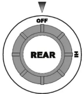
Position OFF Position ON

- WARNING
- IMPORTANT
- IMPORTANT: DO NOT DISCARD THIS MANUAL
- LIMITED WARRANTY STATEMENT
- SERVICE POLICY AND PROCEDURE GUIDE AND ADDITIONAL WARRANTY EXCLUSIONS
- SHIPPING DAMAGE CLAIM PROCEDURE
- IF SHIPMENT ARRIVES DAMAGED
- FILE CLAIM FOR DAMAGE IMMEDIATELY
- TABLE OF CONTENTS
- SPECIFICATIONS
- FEATURES & OPERATING CONTROLS
- PRECAUTIONS AND GENERAL INFORMATION
- AGENCY APPROVAL INFORMATION
- INSTALLATION
- DANGER: HEALTH HAZARD
- WARNING: FIRE HAZARD
- NOTICE
- UNPACKING & INSPECTION
- SETUP
- INSTALLATION (CONTINUED)
- ADDITIONALLY
- FIRE AND
- EXPLOSION HAZARD
- NFPA
- DANGER
- FIRE AND EXPLOSION HAZARD
- FIRE HAZARD
- INSTALLING THE HOTPLATE
- INITIAL ADJUSTMENT
- SET GAS PRESSURE
- SETPILOTFLAMES
- ADJUST BURNER FLAME
- CAUTION: BURN HAZARD
- NOTE
- OPERATION
- IF YOU SMELL GAS
- CAUTION
- BURN HAZARD
- GENERAL OPERATIONAL NOTES
- LIGHTING THE PILOT FLAMES
- IF THE UNIT DOES NOT LIGHT OR IN THE EVENT OF A GAS INTERRUPTION
- SHUT DOWN INSTRUCTIONS
- TROUBLESHOOTING
- CLEANING INSTRUCTIONS (CONTINUED)
- PARTS & SERVICE
- DESCRIPTION
- SERVICE
- PART
- CUSTOMER SERVICE DATA
- WELLS BLOOMFIELD PROUDLY SUPPORTS CFESA COMMERCIAL FOOD EQUIPMENT SERVICE ASSOCIATION
- WELLS MANUFACTURING
- MANUEL D'UTILISATION POUR PLAQUE HAUFFANTE DE OMPTOIR A GAZ
- POUR VOTRE SECURITE
- TABLE DES MATIÈRES
Brand : Wells
Model : H2412G
Category : Cooker