
250H - Solar panel Baxi - Free user manual and instructions
Find the device manual for free 250H Baxi in PDF.
| Product type | Solar thermal collector (solar thermal panel) |
| Brand | Baxi |
| Model | 250H |
| Recommended orientation | South (otherwise west) |
| Tilt angle | Geographic latitude ±10° depending on season, between 15° and 75° |
| Heat transfer fluid | Water-glycol mixture with corrosion inhibitors |
| Glycol concentration | 26% to 51% depending on minimum temperature (down to -35°C) |
| Cold operating pressure | 2 bars (add static pressure) |
| Maximum system pressure | 10 bars |
| Expansion vessel | Mandatory, sized according to DIN 4757 |
| Piping | Copper or stainless steel, minimum slope 1% |
| Pump | Horizontal axis of rotation, installation in the coldest zone |
| Purging | Mandatory before commissioning, manual or automatic air vents |
| Maintenance | Semi-annual check for area >20 m², annual for <20 m² |
| Safety | Safety valve, air vent, frost protection |
| Fluid pH | 7.5 to 8.5 |
| Pressure test | 1.5 times the working pressure |
| Installer required | Competent and approved personnel |
Frequently Asked Questions - 250H Baxi
User questions about 250H Baxi
0 question about this device. Answer the ones you know or ask your own.
Ask a new question about this device
Download the instructions for your Solar panel in PDF format for free! Find your manual 250H - Baxi and take your electronic device back in hand. On this page are published all the documents necessary for the use of your device. 250H by Baxi.
USER MANUAL 250H Baxi
natural_image
Simple line drawing of a tilted rectangular object on an inclined stand, enclosed in a circular frame (no text or symbols)
natural_image
Simple line drawing of a rectangular frame with hatched fill, no text or symbols present
natural_image
Architectural line drawing of a square window frame with brickwork pattern (no text or symbols)- Please read these instructions before installing or commissioning the solar system.
- Please leave these instructions with the user for later reference.
- This solar thermal energy system for domestic hot water should only be installed and handled by competent, authorised personnel.
During works, you must obey:
• The legal provisions on accident prevention.
• Environmental legislation.
- All occupational health and safety provisions in force.
- Specific EU safety regulations and the rules and regulations of the individual country.

Keep the collector protected from the elements and in its original packaging until installation.
To transport the collector, we recommend handling it in its packaging with the aid of aluminium frames. Do not handle the collector by its hydraulic connections. Protect the collector from knocks or other mechanical influences, especially the solar glass, rear of the collector and hydraulic connections.

Cover the collector during installation until it is fully operational, as this will prevent it from reaching high temperatures due to solar radiation.

The installer is responsible for ensuring compliance with all specific regulations in the individual country or region.
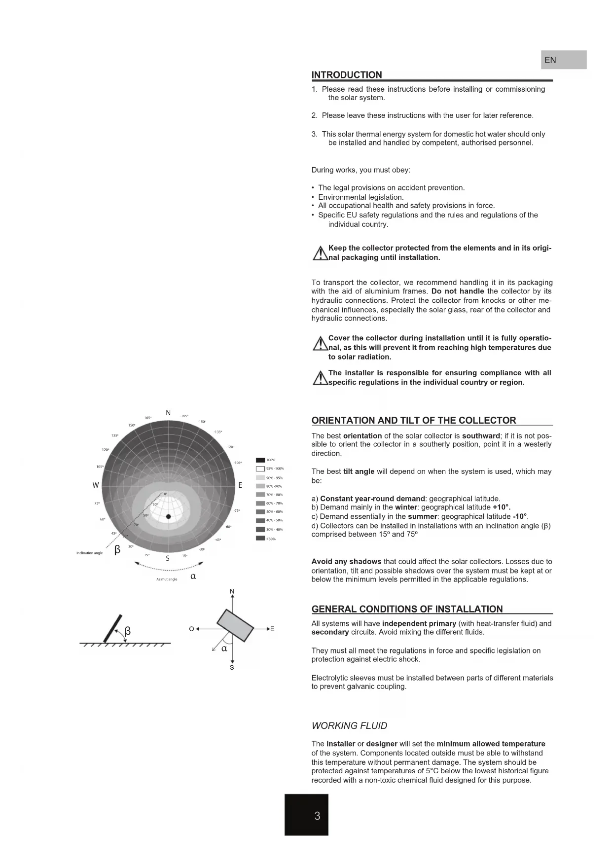
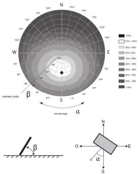
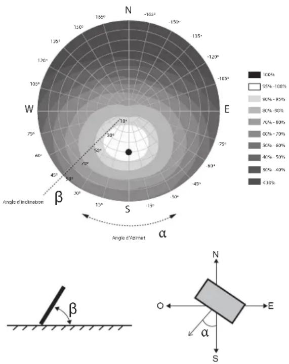
ORIENTATION AND TILT OF THE COLLECTOR
The best orientation of the solar collector is southward; if it is not possible to orient the collector in a southerly position, point it in a westerly direction.
The best tilt angle will depend on when the system is used, which may be:
a) Constant year-round demand: geographical latitude.
b) Demand mainly in the winter: geographical latitude +10°.
c) Demand essentially in the summer: geographical latitude -10°.
d) Collectors can be installed in installations with an inclination angle ( ) comprised between 15° and 75°
Avoid any shadows that could affect the solar collectors. Losses due to orientation, tilt and possible shadows over the system must be kept at or below the minimum levels permitted in the applicable regulations.
GENERAL CONDITIONS OF INSTALLATION
All systems will have independent primary (with heat-transfer fluid) and secondary circuits. Avoid mixing the different fluids.
They must all meet the regulations in force and specific legislation on protection against electric shock.
Electrolytic sleeves must be installed between parts of different materials to prevent galvanic coupling.
WORKING FLUID
The installer or designer will set the minimum allowed temperature of the system. Components located outside must be able to withstand this temperature without permanent damage. The system should be protected against temperatures of 5^ C below the lowest historical figure recorded with a non-toxic chemical fluid designed for this purpose.
radar
| Latitude | Longitude | Value (%) | | :--- | :--- | :--- | | -180°N | 0° | 100 | | -160°N | 30° | 95% - 100% | | -140°N | 60° | 90% - 95% | | -120°N | 90° | 80% - 85% | | -100°N | 120° | 70% - 80% | | -80°N | 150° | 60% - 75% | | -60°N | 180° | 50% - 60% | | -40°N | 210° | 40% - 50% | | -20°N | 240° | 30% - 40% | | 0°N | 270° | <30% | The image displays a polar coordinate system with angular positions (α) and latitude/longitude axes. The diagram includes an inset schematic showing the orientation of the Earth's magnetic field (β) relative to the ground surface.| Freezing point (°C) -10 -15 -20 -25 -30 -32 -35 | ||||
| Glycol concentration (%) 26 33 37 42 47 50 51 |
natural_image
Technical line drawing of a pressure vessel with piping and valves (no text or labels)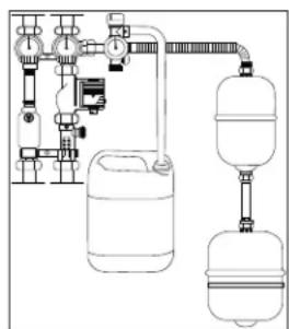
natural_image
Pure schematic diagram of a water circulation system with tanks and valves (no text or labels)We recommend the use of a directly applicable mixture of water and glycol with corrosion inhibitors. Avoid increasing the concentration by large amounts; it should never exceed 50% because this would create a mixture with very high viscosity levels, thereby reducing the heat-transfer properties of the fluid. DO NOT mix with any other fluids.
Although this fluid is non-toxic, odourless and biodegradable, it should be handled with caution. The use of chemical-resistant gloves and eye protection is recommended when handling this fluid.
If the fluid comes into contact with the skin, wash with soap and water. In case of contact with the eyes, rinse immediately with plenty of clean running water.
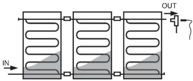
COLLECTOR INSTALLATION
If more than one row is required, the collectors must be installed in a multiple parallel arrangement, preferably with the same number of collectors in each row. Cut-off elements will be installed to separate each row. A safety air vent valve will be installed in each row; if an automatic air vent valve is used, a cut-off valve will be installed to disable the valve while the system is in operation. We must also ensure that there are no reverse flows, as doing so will prevent energy losses.
Temperature probe
Temperature sensors should be installed in such a way as to ensure good contact with the measuring point. They should be insulated from the influence of environmental conditions and installed against the flow of the fluid. The temperature probe will be installed at the hottest point of the output of the corresponding row.
⚠ Ensure correct installation of the thermal sensor in the collector. Secure the sensor wire with a suitable material to prevent its accidental removal from the collector.
⚠️ Special attention must be paid to the maximum temperatures reached in the last collector of the row as the solar liquid may become deteriorated.
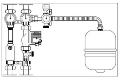
Expansion tank
An expansion tank will be installed in the primary circuit close to the hydraulic unit, in line with the size and characteristics of the installation. The size of the expansion tank will be calculated according to DIN 4757, EN 12977 or VDI 6002. This expansion tank will be installed:
- Such that the temperature of the water touching the membrane is as low as possible.
- Preferably in the pump suction line.
- Cut-off elements should not be installed between the expansion tank and the system.
Pipes
The pipes will be as short as possible and allow for complete draining. Horizontal sections will have a minimum slope of 1%. The pipes of the primary circuit may be made of stainless steel or copper and have threaded, welded or flanged joints. Outdoor pipes must have external protection to enable them to withstand the effect of the weather and avoid transport losses.
The recommended sizes of pipe to maintain a pressure drop of less than 2.5 mbar per linear meter are:
| m^2 | 5 | 7.5 | 12.5 | 25 | ||||||||||||||||
| l/h*m^2 | 15 | 20 | 30 | 40 | 60 | 15 | 20 | 30 | 40 | 60 | 15 | 20 | 30 | 40 | 60 | 15 | 20 | 30 | 40 | 60 |
| l/h | 75 | 100 | 150 | 200 | 300 | 113 | 150 | 225 | 300 | 450 | 188 | 250 | 375 | 500 | 750 | 375 | 500 | 750 | 1000 | 1500 |
| min. int. ∅ | DN13 | DN13 | DN13 | DN16 | DN16 | DN13 | DN13 | DN16 | DN16 | DN20 | DN16 | DN16 | DN20 | DN20 | DN25 | DN20 | DN20 | DN25 | DN25 | DN32 |
Pumps
Where possible, the pump should be assembled in the cooler parts of the circuit, ensuring that there is no cavitation, and always with a horizontal axis of rotation.
To calculate the size of pump to install, we must take account of the pressure drop in the collectors installed, as well as pipe losses.
Collector connection
The optimal connection (parallel connection) is by crossing over the row of input and output collectors from opposite ends; they can be also connected from the same end of the row of collectors with barely any loss of performance.
COMMISSIONING
The first thing we must do after installation is clean the system to remove any residual welding slag, remover or dirt in the pipes.
Use a container large enough to collect the fluid. Once the circuit has been flushed, we can start filling the system.
The system must be filled without direct sunlight; if this is not possible, cover the collector or collectors during filling and flushing. Otherwise, there may be a risk of vapour formation..
Pressurise the system to 1.5 times the working pressure to detect for leaks. If any leaks are detected, eliminate them all from the system.
Alternatively, an air test can be conducted to detect any major losses in the system before flushing and filling with the heat-transfer fluid.
During filling and commissioning, the system must be completely drained. We recommend re-testing the system during the first weeks of operation to release any air
In case of breakdown or drops in the system, you will need to vent the air again when refilling. NEVER fill the primary circuit with tap water if its properties could lead to the formation of incrustations, deposits or attack on the circuit, or if the circuit needs antifreeze due to the risk of frost or any other additive to function properly.
Note: Only operate the air vent when the system is cold. During normal operation, the heat-transfer fluid reaches high temperatures and can cause severe burns.
Check the pH valve at regular intervals to make sure that it is between 7.5 and 8.5. If the fluid is dark or cloudy and the pH value is below 7.0, the heat-transfer fluid must be replaced.
The percentage of glycol in the heat-transfer fluid should be checked every two years. This can be done using a refractometer.
Note that the cold pressure in the collectors should be above 2 bar. Since the filling pressure gauge is located in the bottom part of the installation, we must add the static pressure of the system when taking the reading. The maximum permissible temperature for the system is 10 bar.
After commissioning, do not forget to close all manual and automatic vents.
Once the system has been flushed, drained and has the correct pressure, we must regulate the flow of the system. To do so, we will need to adjust the pump flow to the lowest possible speed (to minimise electrical consumption) and regulate the flow using a flow meter.
The following lists include the most important maintenance operations for an installation.
- Check the proper functioning of the system Perform this checklist during commissioning.
☐ Check the seals and hydraulic connections of the solar collectors to the system.
☐ Check the solar collector mounting kit system.
☐ Check for leaks in the hydraulic circuit.
☐ Check that the heat-transfer fluid used in the system is composed of a mixture of antifreeze and water.
☐ Check the installation of safety elements: expansion tank and safety valve.
☐ Check the connections and operation of the regulation system of the installation.
- Check on general system status
The following checks cover the operations needed to maintain the system within the acceptable limits of operation, performance, protection and durability. These operations must be carried out by competent technical staff with expertise in solar thermal technology and mechanical installations in general. The maintenance register of the system must be kept up to date. The maintenance of systems with a collector area of over 20 m ^2 must undergo inspection at least every six months. Those of less than 20 m ^2 should be inspected on an annual basis.
State of repair of collectors:
| Presence of condensation and dirt | |
| Presence of cracks, deformation | |
| Presence of corrosion | |
| Appearance of leaks | |
| Verification of temperature probe mounting |
State of repair of the collector support structure and its fixing elements:
| Degradation, signs of corrosion and bolt tightening | |
| Condition of collector fixing elements | |
| State of repair of roof around the solar system | |
| Control of vegetation around the collector | |
| Check on ballast tray, where necessary |
Hydraulic circuit:
| Presence of air inside the system | |
| Check on correct operation and cleaning of air valve | |
| Inspection to determine deterioration of insulation | |
| Pressure test | |
| Presence of leaks | |
| Pump seal | |
| Pump operation while the system is running | |
| System flow check | |
| Check on refrigerant density using a refractometer | |
| Check to ensure that the pH value of the refrigerant is pH>7.5 |
Verification of operating pressures:
| Check on system pressure | |
| Check on expansion tank pressure |
Security system
| Actions (opening and closing) to check for cut-off valve stiffness | |
| Presence of glycol in the collection tray | |
| Check on safety valve operation |
Regulation system:
| Check on pump shut-down and start-up differential | |
| Check of reading of the system's temperature sensors |
INTRODUCTION
radar
| Latitude | Longitude | Percentage Range | | :--- | :--- | :--- | | -160° | N | 100% | | -150° | N | 95%-100% | | -120° | N | 90%-95% | | -105° | N | 80%-85% | | -75° | N | 70%-80% | | -50° | N | 60%-70% | | -30° | N | 30%-60% | | -15° | N | 40%-50% | | 0° | N | 40%-50% | | 15° | N | 30%-40% | | 30° | N | <30% | | 45° | N | 30%-40% | | 60° | N | 40%-50% | | 75° | N | 60%-70% | | 100° | N | 80%-90% | | 120° | N | 90%-95% | | 135° | N | 100%-100% |natural_image
Technical line drawing of a pressure vessel with piping and valves (no text or labels)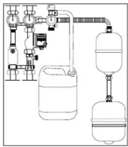
natural_image
Pure schematic diagram of a water circulation system with no text, numbers, or symbolsradar
| Latitude | Longitude | Value (%) | | :--- | :--- | :--- | | -163°N | -150°E | 100 | | -150°N | -120°E | 95 | | -120°N | -105°E | 90 | | -105°N | -80°E | 80 | | -75°N | -45°E | 70 | | -50°N | 0°E | 60 | | -30°N | 30°E | 60 | | -15°N | 45°E | 40 | | 0°N | 60°E | 30 | | 15°N | 75°E | 40 | | 30°N | 90°E | <30 | The image displays a polar coordinate system with angular positions (α, β) and a corresponding diagram showing a line segment labeled 'β' on a surface. The right side is a compass rose to show the direction of the compass. The diagram includes a small rectangular bar labeled 'α' pointing to the right side of the compass. The label 'Angola di inclinzione' indicates the orientation of the angle.natural_image
Pure technical diagram of a piping system with valves and a pressure vessel (no text or labels)
natural_image
Pure schematic diagram of a fluid system with tanks and valves, no text or symbols presentradar
| Angle | Angula de Inclinación | Angula de Azimuth | |-------|------------------------|-------------------| | 0° | 100% | <30% | | 30° | 95%-100% | 30%-40% | | 60° | 90%-95% | 40%-50% | | 90° | 80%-85% | 50%-60% | | 120° | 70%-80% | 60%-70% | | 150° | 60%-70% | 70%-80% | | 180° | 50%-60% | 80%-90% | | 210° | 40%-50% | 90%-100% | | 240° | 30%-40% | 100% | | 270° | 20%-30% | 95%-100% | | 300° | 10%-20% | 90%-100% | | 330° | 5%-15% | 80%-90% | | 360° | 15%-25% | 70%-80% | | 390° | 25%-35% | 60%-70% | | 420° | 35%-45% | 50%-60% | | 450° | 45%-55% | 40%-50% | | 480° | 55%-65% | 30%-40% | | 510° | 65%-75% | 20%-30% | | 540° | 75%-85% | 10%-20% | | 570° | 85%-95% | <30% | | N | -15° | <30% | | E | -25° | <30% | | W | -35° | <30% | | N | -45° | <30% | | E | -55° | <30% | | W | -65° | <30% | | N | -75° | <30% | | E | -85° | <30% | | W | -95° | <30% | | N | -105° | <30% | | E | -115° | <30% | | W | -125° | <30% | | N | -135° | <30% | | E | -145° | <30% | | W | -155° | <30% | | N | -165° | <30% | | E | -175° | <30% | | W | -185° | <30% | | N | -195° | <30% | | E | -205° | <30% | | W | -215° | <30% | | N | -225° | <30% | | E | -235° | <30% | | W | -245° | <30% | | N | -255° | <30% | | E | -265° | <30% | | W | -275° | <30% | | N | -285° | <30% | | E | -295° | <30% | | W | -305° | <30% | | N | -315° | <30% | | E | -325° | <30% | | W | -335° | <30% | | N | -345° | <30% | | E | -355° | <30% | | W | -365° | <30% | | N | -375° | <30% | | E | -385° | <30% | | W | -395° | <30% | | N | -405° | <30% | | E | -415° | <30% | | W | -425° | <30% | | N | -435° | <30% | | E | -445° | <30% | | W | -455° | <30% | | N | -465° | <30% | | E | -475° | <30% | | W | -485° | <30% | | N | -495° | <30% | | E | -505° | <30% | | W | -515° | <30% | | N | -525° | <30% | | E | -535° | <30% | | W | -545° | <30% | | N | -555° | <30% | | E | -565° | <30% | | W | -575° | <30% | | N | -585° | <30% | | E | -595° | <30% | | W | -605° | <30% | | N | -615° | <30% | | E | -625° | <30% | | W | -635° | <30% | | N | -645° | <30% | | E | -655° | <30% | | W | -665° | <30% | | N | -675° | <30% | | E | -685° | <30% | | W | -695° | <30% | | N | -705° | <30% | | E | -715° | <30% | | W | -725° | <30% | | N | -735° | <30% | | E | -745° | <30% | | W | -755° | <30% | | N | -765° | <30% | | E | -775° | <30% | | W | -785° | <30% | | N | -795° | <30% | | E | -805° | <30% | | W | -815° | <30% | | N | -825° | <30% | | E | -835° | <30% | | W | -845° | <30% | | N | -855° | <30% | | E | -865° | <30% | | W | -875° | <30% | | N | -885° | <30% | | E | -895° | <30% | | W | -905° | <30% | | N | -915° | <30% | | E | -925° | <30% | | W | -935° | <30% | | N | -945° | <30% | | E | -955° | <30% | | W | -965° | <30% | | N | -975° | <30% | | E | -985° | <30% | | W | -995° | <30% | | N | -100⁰ | <30% | The chart displays a polar bar chart with angular positions (α) on the x-axis and corresponding angular values (β) on the y-axis. The data is presented in a grid format with color-coded bars indicating the magnitude of the angle at each position. The legend indicates the angle ranges from approximately 1 to over 1. The chart is divided into three parts: (Top) for angles ≤9, (Middle) for angles ≥9, and (Bottom) for angles ≤9. The chart is created using a polar plot with a color scale from lightest to darkest. The color scale is defined by the number of pixels in parentheses. The chart is saved as a PNG file named 'Angula de Inclinación' and 'Angula de Azimuth'.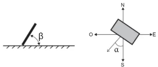
natural_image
Technical line drawing of a pressure vessel with piping and valve components (no text or labels)
natural_image
Pure schematic diagram of a water circulation system with tanks and piping (no text or labels)natural_image
Technical line drawing of a pressure vessel with piping and valves (no text or labels)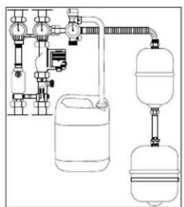
natural_image
Pure schematic diagram of a gas supply system with tanks and piping (no text or labels)natural_image
Pure technical diagram of a piping system with valves and a pressure vessel (no text or labels)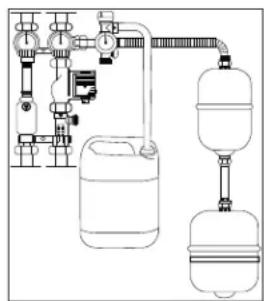
natural_image
Pure schematic diagram of a water circulation system with no text, numbers, or symbolsALLGEMEINE INSTALLATIONSBEDINGUNGEN
natural_image
Technical line drawing of a pressure vessel with piping and valves (no text or labels)
natural_image
Pure schematic diagram of a water supply system with tanks, valves, and piping (no text or labels)natural_image
Pure technical diagram of a piping system with valves and a pressure vessel (no text or labels)
natural_image
Pure schematic diagram of a water supply system with tanks, valves, and piping (no text or labels)


Brand : Baxi
Model : 250H
Category : Solar panel