4U26HS1ERA - Air Conditioning HAIER - Free user manual and instructions
Find the device manual for free 4U26HS1ERA HAIER in PDF.


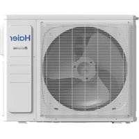
| Brand | Haier |
| Model | 4U26HS1ERA |
| Product type | Multi-split air conditioning (multiple indoor units) |
| Refrigerant | R410A (GWP 1975) |
| Power supply | 1 phase, 220-230 V, 50/60 Hz |
| Fuse | T3.15A / T16A 250VAC (depending on model) |
| Max. pipe length per indoor unit | 25 m |
| Max. total pipe length | 70 m |
| Standard liquid pipe length | 40 m |
| Pipe diameters (liquid/gas) | 6.35 mm (1/4") / 9.52 mm (3/8") or 12.7 mm (1/2") |
| Main functions | Cooling, heating, silent mode (DIP SW5-8) |
| Wiring error control | Automatic via DIP SW and LED display |
| Sensors | Ambient temperature, suction, discharge, pipes, defrost, condensation |
| Safety | High/low pressure protection, overcurrent, overheating, pressure switches |
| Supplied accessories | Drain elbow, rubber damper, cap, adapters (3/8→1/2, 1/2→3/8) |
| Maintenance and cleaning | Keep the area around the outdoor unit clean, avoid obstructions |
| Repairability | Spare parts available: sensors, modules, valves, fan motors |
| CE compliance | Directives 73/23/EEC, 2006/95/EC, 89/336/EEC, 2004/108/EC, RoHS, WEEE |
Frequently Asked Questions - 4U26HS1ERA HAIER
User questions about 4U26HS1ERA HAIER
0 question about this device. Answer the ones you know or ask your own.
Ask a new question about this device
Download the instructions for your Air Conditioning in PDF format for free! Find your manual 4U26HS1ERA - HAIER and take your electronic device back in hand. On this page are published all the documents necessary for the use of your device. 4U26HS1ERA by HAIER.
USER MANUAL 4U26HS1ERA HAIER
- Please read this manual carefully before installation.
- Keep this operation manual for future reference.
No.0150508607 C


3U19FS1ERA
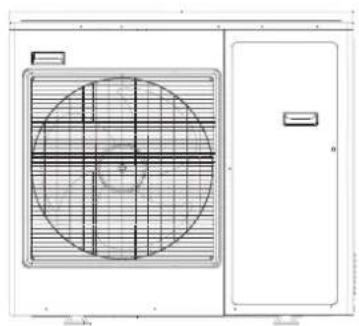
4U25HS1ERA
4U30HS1ERA
5U34HS1ERA
Contents
Safety Precautions 3
4
Precautions for Selecting the
Location 4
Installation drawings of indoor and
outdoor units 5
Precautions on Installation 7
Outdoor Unit Installation Guideline 7
Limitations on the installation 7
Refrigerant piping work 7
Pump Down Operation 12
Wiring work 12
Test running 14
Trouble shooting 15
- Please read this manual carefully before installation.
Keep this operation manual for future reference.
EUROPEAN REGULATIONS CONFORMITY FOR THE MODELS
CE
All the products are in conformity with the following European provision:
- Low Voltage Directive 73/23/EEC
- Low Voltage Directive 2006/95/EC
-Electromagnetic CompatibilityY 89/336/EEC
-Electromagnetic CompatibilityY 2004/108/EC
ROHS
The products are fulfilled with the requirements in the directive 2002/95/EEC of the European parliament and of council on the Restriction of the use of Certain Hazardous Substances in Electrical and Electronic Equipment (EU RoHS Directive)
WEEE
In accordance with the directive 2002/96/CE of the European parliament, herewith we inform the consumer about the disposal requirements of the electrical and electronic products.
DISPOSAL REQUIREMENTS:

Your air conditioning product is marked with this symbol. This means that electrical and electronic products shall not be mixed with unsorted household waste. Do not try to dismantle the system yourself: the dismantling of the air
conditioning system, treatment of the refrigerant, of oil and of other part must be done by a qualified installer in accordance with relevant local and national legislation. Air conditioners must be treated at a specialized treatment facility for reuse, recycling and recovery. By ensuring this product is disposed of correctly, you will help to prevent potential negative consequences for the environment and human health. Please contact the installer or local authority for more information. Battery must be removed from the remote controller and disposed of separately in accordance with relevant local and national legislation.
IMPORTANT INFORMATION REGARDSING THE REFRIGERANT USED

This product contains fluorinated greenhouse gases covered by the Kyoto Protocol. Do not vent into the atmosphere.
Refrigerant type:R410A
GWP* value:1975
GWP=global warming potential
Please fill in with indelible ink,
- 1 the factory refrigerant charge of the product
-
2 the additional refrigerant amount charged in the field and
-
1 + 2 the total refrigerant charge
on the refrigerant charge label supplied with the product.
The filled out label must be adhered in the proximity of the product charging port (e.g. onto the inside of the stop value cover).
A contains fluorinated greenhouse gases covered by the Kyoto Protocol
B factory refrigerant charge of the product: see unit name plate
C additional refrigerant amount charged in the field
D total refrigerant charge
E outdoor unit
F refrigerant cylinder and manifold for charging
Safety Precautions
- Read these Safety Precautions carefully to ensure correct installation.
- This manual classifies the precautions into WARNING and CAUTION.
- Be sure to follow all the precautions below: they are all important for ensuring safety.

WARNING Failure to follow any of WARING is likely to result in such grave consequences as death or serious injury.
CAUTION Failure to follow any of CAUTION may in some cases result in grave consequences.
- The following safety symbols are used throughout this manual:

Be sure to observe this instruction Be able to establish an earth connection Never attempt
- After completing installation, test the unit to check for installation errors. Give the user adequate instructions concerning the use and cleaning of the unit according to the Operation Manual.
| WARNING |
| • Installation should be left to the dealer or another professional. Improper installation may cause water leakage, electrical shock, or fire. |
| • Install the air conditioner according to the instructions given in this manual. Incomplete installation may cause water leakage, electrical shock, or fire. |
| • Be sure to use the supplied or specified installation parts. Use of other parts may cause the unit to cometo lose, water leakage, electrical shock, or fire. |
| • Install the air conditioner on a solid base that can support the unit's weight. An inadequate base or incomplete installation may cause injury in the event the unit falls off the base. |
| • Electrical work should be carried out in accordance with the installation manual and the national electrical wiring rules or code of practice. Insufficient capacity or incomplete electrical work may cause electrical shock or fire. |
| • Be sure to use a dedicated power circuit. Never use a power supply shared by another appliance. |
| • For wiring, use a cable long enough to cover the entire distance with no connection. Do not use an extension cord. Do not put other loads on the power supply, use a dedicated power circuit. (Failure to do so may cause abnormal heat, electric shock or fire.) |
| • Use the specified types of wires for electrical connections between the indoor and outdoor units. Firmly clamp the interconnection wires so their terminals terminals receive no external stresses. Incomplete connections or clamping may cause terminal overheating or fire. |
| • After connectiong interconnecting and supply wiring be sure to shape the cables so that they do not put undue force on the electrical covers or panels. Install covers over the wires. Incomplete cover installation may cause terminal overheating, electrical shock, or fire. |
| • If any refrigerant has leaked out during the installation work, ventilate the room. (The refrigerant produces a toxic gas if exposed to flames.) |
| • After all installation is complete, check to make sure that no refrigerant is leaking out. (The refrigerant produces a toxic gas if exposed to flames.) |
| • When installing or relocating the system, be sure to keep the refrigerant circuit free from substances other than the specified refrigerant(R410A), such as air. (Any presence of air or other foreign substance in the refrigerant circuit causes an abnormal pressure rise or rupture, resulting in injury.) |
| • During pump-down, stop the compressor before removing the refrigerant piping. If the compressor is still running and the stop valve is open during pump-down, air will be sucked in when the rcompressor is run, causing abnormal pressure in the freezer cycle which will lead to breakage and even injury. |
| • Be sure to establish an earth. Do not earth the unit to a utility pipe, arrester, or telephone earth. In complete earth may cause electrical shock, or fire. A high surge current from lightning or other sources may cause damage to the air conditioner. |
| • Be sure to install an earth leakage breaker. Failure to install an earth leakage breaker may result in electric shocks, or fire. |
| CAUTION |
| Do not install the aire conditioner in a place where there is danger of exposure to inflammable gas leakage. If the gas leaks and builds up around the unit, it may catch fire. |
| Establish drain piping according to the instructions of this manual. Inadequate piping may cause flooding. |
| Tighten the flare nut according to the specified method such as with a torque wrench. If the flare nut is tightened too hard, the falre nut may crack after a long time and cause refrigerant leakage. |
| Make sure to provide for adequate measures in order to prevent that the outdoor unit be used as a shelter by small animals. Small animals making contact with electrical parts can cause malfunctions, smoke or fire. Please instruct the customer to keep the area around the unit clean. |
Accessories supplied with the outdoor unit:
| No. | Drawing | Name of parts | Quantity | Note |
| 1 | Drainage elbow | 1 | 3U19FS1ERA | |
| 3 | 4U25HS1ERA 5U34HS1ERA 4U30HS1ERA | |||
| 2 | Rubber cushion | 4 | 3U19FS1ERA 4U30HS1ERA 4U25HS1ERA 5U34HS1ERA | |
| 3 | Clap | 1 | 3U19FS1ERA | |
| 3 | 4U25HS1ERA 5U34HS1ERA 4U30HS1ERA | |||
| 4 | Adaptor(3/8→1/2) | 1 | 3U19FS1ERA 4U30HS1ERA 4U25HS1ERA 5U34HS1ERA | |
| 5 | Adaptor(1/2→3/8) | 1 | 4U25HS1ERA 5U34HS1ERA 4U30HS1ERA |
Precautions for Selecting the Location
1) Choose a place solid enough to bear the weight and vibration of the unit, where the operation noise will not be amplified.
2) Choose a location where the hot aire discharged from the unit or the operation noise, will not cause a nuisance to the neighbors of the user.
3) Avoid places near a bedroom and the like, so that the operation noise will cause no trouble.
4) There must be sufficient space for carrying the unit into and out of the site.
5) There must be sufficient space for air passage and no obstructions around the air inlet and the air outlet.
6) The site must be free from the possibility of flammable gas leakage in a nearby place.
Locate the unit so that the noise and the discharged hot air will not annoy the neighbors.
7) Install units, power cords and inter-unit cables at least 3 meter away from television and radio sets. This is to prevent interference to images and sounds. (Noises may be heard even if they are more than 3 meter away depending on radio wave conditions.)
8) In coastal areas or other places with salty atmosphere of sulfate gas, corrosion may shorten the life of the air conditioner.
9)Since drain flows out of the outdoor unit, do not place under the unit anything which must be kept away from moisture.
NOTE:
Cannot be installed hanging from ceiling or stacked.

CAUTION
When operationg the air conditioner in a low outdoor ambient temperature, be sure to follow the instructions described below.
1) To prevent exposure to wind, install the outdoor unit with its suction side facing the wall.
2) Never install the outdoor unit at a site where the suction side may be exposed directly to wind.
3) To prevent exposure to wind, it is recommended to install a baffle plate on the air discharge side of the outdoor unit.
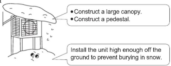
4) In heavy snowfall areas, select an installation site where the snow will not affect the unit.
Installation drawings of indoor and outdoor units
- Do not connected the embedded branch piping and the outdoor unit when only carrying out piping work without connecting the indoor unit in order to add another indoor unit later. Make sure no dirt or mositure gets into eigher side of the embedded branch piping.
2.It is impossible to connect the indoor unit for one room only.

If there is the danger of the unit falling or overturning, fix the unit with foundation bolts, or with wire or other means.
If the location does not have good drainage, place the unit on a level mounting base(or a plastic pedestal).
Install the outdoor unit in a level position. Failure to do so may result in water leakage or accumulation.
Installation drawings of indoor and outdoor units
| Connection cautions | |||
| model 3U19FS1ERA | 4U25HS1ERA 4U30HS1ERA | 5U34HS1ERA | |
| connection priority between indoor and stop valve higher from down to up | |||
| when there is 1 indoor,the prior stop valve is | C | D | E |
| when there are 2 indoors,the prior stop valves are | C B | D C | E D |
| when there are 3 indoors,the prior stop valves are | C B A | D C B | E D C |
| when there are 4 indoors,the prior stop valves are | D C B A | E D C B | |
| when there are 5 indoors,the prior stop valves are | E D C B A | ||
| Note: For better oil return and more reliable system, please execute as the above when connecting indoor unit. | |||
- Check the strength and level of the installation ground so that the unit will not cause any operating vibration or noise after installed.
- In accordance with the foundation drawing in fix the unit securely by means of the foundation bolts.(Prepare four sets of M8 or M10 foundation bolts, nuts and washers each which are available on the market.)
- It is best to screw in the foundation bolts until their length are 20mm from the foundation surface.

Outdoor Unit Installation Guideline
- Where a wall or other obstacle is in the path of outdoor unit's intake or exhaust airflow, follow the installation guidelines below.
- For any of the below installation patterns, the wall height on the exhaust side should be 1200mm or less.
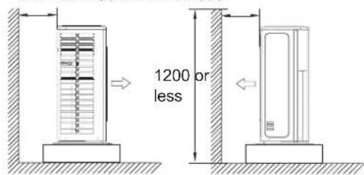
Wall facing one side
More than 50 More than 300
Side view

Wall facing two sides
Side view

than 50

Wall facing three sides
Side view
Limitations on the installation
1.Precautions on installation
- Check the strength and level of the installation ground so that unit will not cause any operating vibration or noise after installation
In accordance with the foundation drawing in fix the unit securely by means of the foundation bolts. - It is best to screw in the foundation bolts unit their length are 20mm from the foundation surface.
2. Selecting a location for installation of the indoor units
- The maximum allowable length of refrigerant piping, and the maximum allowable height difference between the outdoor and indoor units, are listed below. (The shorter the refrigerant piping, the better the performance. Connect so that the piping is as short as possible. Shortest allowable length per room is 3m)
| Outdoor unit capacity class | 3U19FS1ERA | 4U25HS1ERA 4U30HS1ERA | 5U34HS1ERA |
| Piping to each indoor unit | 25m max. | 25m max. | 25m max. |
| Total length of piping between all lunits | 50m max. | 70m max. | 80m max. |

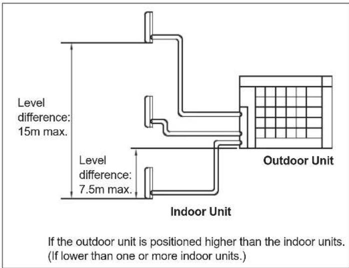

Refrigerant piping work
1. Installing outdoor unit
1) When installing the outdoor unit, refer to "Precautions for Selecting the Location" and the "Indoor/Outdoor Unit Installation Drawings". 2) If drain work is necessary, follow the procedures below.
2. Drain work
1) Use drain plug for drainage.
2) If the drain port is covered by a mounting base or floor surface, place additional foot bases of at least 30mm in height under the outdoor unit's feet.
3) In cold areas, do not use a drain hose with the outdoor unit. (Otherwise, drain water may freeze, impairing heating performance.)

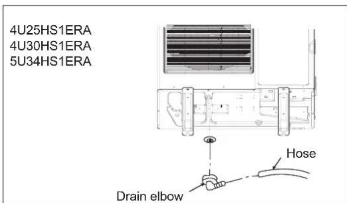
3. Refrigerant piping work
1). Align the centres of both flares and tighten the flare nuts 3 or 4 turns by hand. Then tighten them fully with the tor wrenches. Use torque wrenches when tightening the flare nuts to prevent damage to the flare nuts and escaping gas.
| Flare nut fighting torque | |
| Flare nut for ∅ 6.35 | 14.2-17.2N.m(144-175kgf.cm) |
| Flare nut for ∅ 9.52 | 32.7-39.9N.m(333-407kgf.cm) |
| Flare nut for ∅ 12.7 | 49.5-60.3N.m(505-615kgf.cm) |
| Flare nut for ∅ 15.88 | 61.8-75.4N.m(630-769kgf.cm) |

| Valve cap tightening torque |
| Liquid pipe 26.5-32.3N.m(270-330kgf.cm) |
| Gas pipe 48.1-59.7N.m(490-610kgf.cm) |
| Service port cap tightening torque |
| 10.8-14.7N.m(110-150kgf.cm) |

2)To prevent gas leakage, apply refrigeration oil on both inner and outer surfaces of the flare. (Use refrigeration oil for R410A)
4. Purging air and checking gas leakage
When piping work is completed, it is necessary to purge the air and check for gas leakage.
WARNING
1) Do not mix any substance other than the specified refrigerant (R410A) into the refrigeration cycle.
2) When refrigerant gas leaks occur, ventilate the room as soon and as much as possible.
3) R410A, as well as other refrigerants, should always be recovered and never be released directly into the environment.
4) Use a vacuum pump for R410A exclusively. Using the same vacuum pump for different refrigerents may damage the vacuum pump or the unit.
If using additional refrigerant, perform air purging from the refrigerant pipes and indoor unit using a vacuum pump, then charge additional refrigerant.
- Use a hexagonal wrench (4mm) to operate the stop valve rod.
- All refrigerant pipe joints should be tightened with a torque wrench at the specified tightening torque.
Connect projection side of charging hose(Which comes from gauge manifold) to gas stop valve's service port.

Fully open gauge manifold's low-pressure valve(Lo) and completely close its high-pressure valve(Hi). (High-pressure valve subsequently requires no operation.)

Apply vacuum pumping. Check that the compound pressure gauge reads-0.1MPa(-76cmHg). Evacuation for at lease 1 hour is recommended.

Close gauge manifold's low-pressure valve(Lo) and stop vacuum pump. (Leave as is for 4-5 minutes and make sure the coupling meter needle does not go back. If it does go back, this may indicate the presence of moisture or leaking from connecting parts. After inspecting all the connection and loosening then retightening thenuts, requat steps 2-4.)

Remove covers from liquid stop valve and gas stop valve.

Turn the liquid stop valve's rod 90 degrees counterclockwise with a hexagonal wrench to open valve. Close it after 5 seconds, and check for gas leakage. Using soapy water, check for gas leakage from indoor unit's flare and outdoor unit's flare and valve rods. After the check is complete, wipe all soapy water off.

Disconnect charging hose from gas stop valve's service port, then fully open liquid and gas stop valves. (Do not attempt to turn valve rodj beyond its stop.)

Tighten valve caps and service port caps for the liquid and gas stop valves with a torque wrench at the specified torques. See "3 Refrigerant piping" on page 6 for details.
5. Refilling the refrigerant
Check the type of refrigerant to be used on the machine namiplate.
Precautions when adding R410A
Fill from the liquid pipe in liquid form.
It is a mixed refrigerant, so adding it in gas form may cause the refrigerant composition to change, preventing normal operation.
1) Before filling, check whether the cylinder has a siphon attached or not.(It should have something like "liquid filling siphon attached" displayed on it.)
Filling a cylinder with an attached siphon
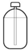
Stand the cylinder upright when filling.
There is a siphon pipe inside, so the cylinder need not be upside-down to fill with liquid.
Filling other cylinders

Turn the cylinder upside-down when filing.
2) Be sure to use the R410A tools to ensure pressure and to prevent foreign objects entering.
6. Charging with refrigerant
1) This system must use refrigerantsant R410A.
2) Add refrigerant 20g per meter when the total piping length exceeds the standard value, but make sure that the total liquid piping length should be less than the max. value.
| Outdoor Unit | Standard total liquid piping length | Max. total liquid piping length |
| 3U19FS1ERA | 30m | 50m |
| 4U25HS1ERA | 40m | 70m |
| 4U30HS1ERA | 40m | 70m |
| 5U34HS1ERA | 40m | 80m |
Notes:
1) When using this product, you need not to set the address. But the L/N wires between indoor & outdoor units must be corresponded, or there will be communication failure.
2) Quiet Operation Setting. Set the DIP "8" to ON position of SW5, the system will run with lower noise, but the max. capacity will also reduce slightly.
3) Do not change the settings of other switches, wrong settings can make the system damage or other malfunctions.
7.Precautions for Laying Refrigerant Piping
- Cautions on pipe handling
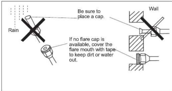
1) Protect the open end of the pipe against dust and moisture.
2) All pipe bends should be as gentle as possible. Use a pipe bender for bending.(Bending radius should be 30 to 40mm or larger.)
- Selection of copper and heat insulation materials
When using commercial copper pipes and fittings, observe the following :
1) Insulation material: Polyethylene foam
Heat transfer rate: 0.041 to 0.052W / mK (0.035 to 0.045kcal/mh°C)
Refrigerant gas pipe's surface temperature reaches 110^ max.
Choose heat insulation materials that will withstand this temperature.
2) Be sure to insulate both the gas and liquid piping and to provide insulation dimensions as below.
| Gas pipe | Gas pipe insulation |
| O.D.:9.52mm,12.7mm Thickness:0.8mm | I.D.:12-15mm,12.7mm Thickness:13mm min. |
| Liquid pipe | Liquid pipe insulation |
| O.D.:6.35mm Thickness:0.8mm | I.D.:18-10mm Thickness:10mm min. |
3) Use separate thermal insulation pipes for gas and liquid refrigerant pipe.
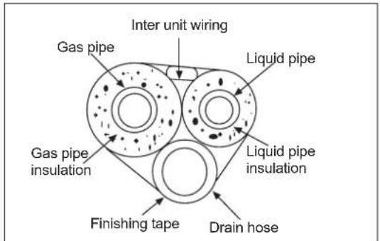
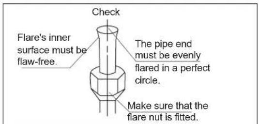

| Flare tooling die | Flare tool for R410A | Conventional flare tool | |
| Clutch-type | Clutch-type(Rigid-type) | Wing-nuttype(Imperial-type) | |
| 0-0.5mm | 1.0-1.5mm | 1.5-2.0mm | |
8.Cutting and Flaring work of piping
- Pipe cutting is carried out with a pipe cutter and burs must be removed.
After inserting the flare nut, flaring work is carried out.
| Flare tooling die | Pipe | Pipe diameter Size A (mm) | |
| Liquid side | 6.35mm(1/4") | 0.8~1.5 | |
| Gas side | 9.52mm(3/8") | 1.0~1.5 | |
| 12.7mm(1/2") | 1.0~1.5 | ||
| Correct Incorrect | |
| Lean Damage of flare Crack Partial Too outside | |
9. On drainage
- Please install the drain hose so as to be downward slope without fail. Please don't do the drainage as shown below.

It becomes high midway.

The end is immersed in water. It waves.


It gap with the ground its too small.

There is the bad smell from a ditch.
- Please pour water in the drain pan of the indoor unit, and confirm that drainage is carried out serely to outdoor.
- In case that the attached drain hose is in a room, please apply heat insulation to it without fail.

WARNING
1) Do not use mineral oil on flared part.
2) Prevent mineral oil from getting into the system as this would educe the lifetime of the units.
3) Never use piping which has been used for previous installations. Only use parts which are delivered with the unit.
4) Do never install a drier to this R410A unit in order to guarantee its lifetime.
5) The drying material may dissolve and damage the system.
6) Incom; ete flaring may cause refrigerant gas leakage.
In order to protect the environment, be sure to pump down when relocating or disposing of the unit.
1) Remove the valve caps from liquid stop valve and gas stop valve.
2) Carry out forced cooling operation.
3) After five to ten minutes, close the liquid stop valve with a hexagonal wrench.
4) After two to three minutes, close the gas stop vaile and stop forced cooling operation.

Wiring work
1. Electric wiring
- The air conditioner must use special circuit, and wiring by the qualified electrician according to the wiring rules specified in national standard.
- The grounding wire and the neutral wire shall be strictly separated. Connect the neutral wire with grounding wire is incorrect.
- The electric leakage breaker must be installed.
- All the electric wire must be copper wire. Power supply: 1PH, 220-230V~, 50/60Hz.
- The wiring method of power line is Y connection. If the power line is damaged, in order to avoid risk of electric shock, it must be replaced by the manufacturer or its repair center or other similar qualified person. The connecting cable must be shielded.
Fuse: T3.15A 250VAC T16A 250VAC (Please check with the outdoor unit wiring diagram.)
- Please check the circuit diagram about the fuse replaced.
2. Wiring method
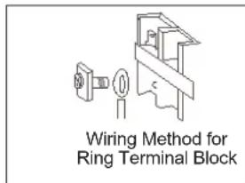
- Wiring method of orbicular terminals
For the connection wire with orbicular terminals, its wiring method is as shown in the right figure: remove the connecting screw, put the screw through the ring on the end of the wire, then connect to the terminal block and fasten screw. Wiring method of straight terminals.
- For the connection wire without orbicular terminals, its wiring method is: loosen the connection screw, and insert the end of the connection wire completely into the Terminal block, then fasten the screw.
Slightly pull the wire outwards to confirm it is firmly held.
- Crimp connection method for wires without terminals
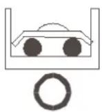
Connect the wire with same diameter to the two sides of the terminal

Do not connect the wire with same diameter to the same side

Do not connect the wire with different diameters

Correct Pressing
Terminal block

Pressing Clamps
Wrong Pressing
- Crimp connection method for connection wire
After connection, the wire must be fastened by wire cover. The wire cover shall press on the protection coat of the connection wire, as shown in right top figure.
Note: When connecting the wiring, confirm the terminal number of indoor and outdoor units carefully.
Incorrect wiring will damage the controller of air conditioner or the unit can not operate.
3. Wiring method of outdoor unit:
Power line
Remove the repair board of the outdoor unit and loosen the wire cover A, then put the live wire, neutral wire and grounding wire through the wire cover ,and connect them to terminal block correspondingly. After connection, fasten wire cover to its previous state.
Communication wire of indoor unit.
- Loosen wire cover, put the communication wire through the wire cover B, and connect them to terminal block correspondingly. After connection, fasten wire cover B to its previous state.
Note: Power line and communication wire are provided by consumers themselves.


4. Wiring method of indoor unit
Loosen wire cover and connect the power line and communication wire of indoor unit to the terminal correspondingly.
Note:
When connecting power line to power supply terminal, please pay attention to the following items:
- Do not connect the power line with different dimensions to the same connection wire end. Improper contact will cause heat generation.
- Do not connect the power line with different dimensions to the same grounding wire end. Improper contact will affect protection.
- Do not connect the power line to the connecting end of communication wire. Incorrect connection will cause damage to the connected unit.
5. Example wiring diagram.
Wiring diagram please refers to 4U30HS1ERA

Before starting the test running, please confirm the following works have been done successfully.
1) Correct piping work;
2) Correct wiring work;
3) Correct match of indoor and outdoor unit;
4) Proper recharge of refrigerant if needed.
-
Make sure that all the stop valves are fully open.
-
Check the voltage supplied to the outdoor and indoor units, please confirm that is 230V .
Wiring Error Check
This product is capable of automatic checking of wiring error.
Switch on all the 4 dip-switches on the outdoor unit small service PC-board as shown on the right. Then power off the unit and power on again, the system will enter the operation of "Wiring Error Check". After 3 minutes stand-by, the unit starts for automatic wiring checking.
Approximately 30 50 minutes (depends on how many units installed in the system) after the unit starts, the Errors of the wiring will be shown by the LEDs (1 to 5).

During this operation, the digital-number will alternately show the compressor working frequency (e.g. 50 stands for the current running frequency) and letter "CH"(means checking).
After this operation, if all the wiring is correct, the digital-number will show "0", if there has wrong wiring, the digital-number will show "EC"(error connection) and also it will flashing.
The service monitor LEDs indicate the error of wiring, as shown in the table below. For details about how to read the LED display, refer to the service manual.
If self-checking is not possible, check the indoor unit wiring and piping in the usual manner.
| LED | 1 | 2 | 3 | 4 | 5 | Message |
| Status | OFF | Unit not connected | ||||
| ALL Flashing | Automatic checking impossible, all units connect wrong | |||||
| ALL ON | All units connect correctly | |||||
| ON | FLASHING | FLASHING | ON | FLASHING | ON: unit connect correctly FLASHING: unit connect wrong, need to change the wiring manually between 2,3,and 5 | |
| ON | FLASHING | FLASHING | ON | ON | ON: unit connect correctly FLASHING: unit connect wrong, need to change the wiring manually between 2,3 | |
| Only one LED flashing | Abnormal | |||||
Test running.
1) If the temperature is lower than 16^ , it is impossible to test cooling with remote controller, and also when the temperature is higher than 30^ , it is impossible to test heating.
2) To test cooling, set the lowest temperature at 16^ . To test heating, set the highest temperature, at 30^ .
3) Please check both cooling and heating operation of each unit individually and then also check the simultaneous operation of all indoor units.
4) After ruining the unit for about 20 minutes, check the indoor unit outlet temperature.
5) After the unit is stopped, or working mode changed, the system will not start again for about 3 minutes.
6) During cooling operation, frost may occur on the indoor unit or pipes, this is normal.
7) Operate the unit according to the operation manual. Please kindly explain to our customers how to operate through the instruction manual.
- Seven-segment numeric display
1) When unit is runing, this seven-segment numeric will display the frequency of compressor. For example, "4" means compressor running frequency is 40 Hz, "7" means compressor running frequency is 108Hz.
2) When faulty happens, seven-segment numeric will flash and display some numbers, this number is failure code. For example, a flashing "32" means No.32 failure, that is indoor and outdoor communication error.

- Communication LED
5 green LED means 5 indoor units. If one LED keep lighting that means the corresponding indoor unit has good communication with outdoor unit. If one LED is not lighting, that means there is no communication between indoor and outdoor.
| Malfunction Code | Diagnosis | Possible reasons |
| 1 | Faulty of outdoor unit EEPROM Communication failure between Module and ECU | Faulty of outdoor unit EEPROM |
| 2 | Communication cables broken or not well connected.IPM overcurrent or short circuit | IPM on the module overcurrent,or short circuit |
| 4 | Communication failure between Module and ECU | Communication cables broken,or not be well connected,or faulty main ECU,or faulty module |
| 5 Module operated overload Module worked overload | ||
| 6 | Module low or high DC voltage (under 192V or above 375V) | VDC<192V or VDC ≥75V |
| 8 | Discharging temperature overheating.Lack of refrigerant, ambient temperature too high or PMVs blocked. | Discharging temperature overheating.Lack of refrigerant,ambient temperature too high or PMVs blocked. |
| 9 | Malfunction of the DC fan motor | Fan is blocked,or the terminal is disconnected from the ECU |
| 10 Malfunction of defrosting temp. sensor(Te) Sensor disconnected,or broken,or at wrong position or short circuit | ||
| 11 | Malfunction of compressor suction temp. sensor (Ts) | Sensor disconnected,or broken,or at wrong position or short circuit |
| 12 Malfunction of ambient temp. sensor(Ta) Sensor disconnected,or | broken,or at wrong position or short circuit | |
| 13 | Malfunction of compressor discharge temp. sensor (Td) | Sensor disconnected,or broken,or at wrong position or short circuit |
| 15 | Communication failure between indoor&outdoor unit | Wrong connection,or the wires be disconnected,or faulty ECU,or faulty power supply |
| 17 | 4-way valve switching failure | Coil of 4-way valve is disconnected,or faulty outdoor ECU |
| 18 | Module overcurrent / Module switch failure | Module switch failure,or faulty module |
| 20 Indoor overload | Indoor overload | |
| 21 Indoor frosted | Indoor frosted | |
| 23 | Module temperature too high (Overload Protector) | Module temperature too high,or the temperature sensor broken(detected by the ECU) |
| 24 | Compressor overcurrent | Over current of the compressor,or malfunction of the module |
| 25 Input overcurrent | Over current of the system,or malfunction with indoor or outdoor fan motors,or faulty ECU | |
| 26 | MCU reset | MCU on the ECU reset |
| 27 | Module current detect circuit malfunction | Current detect circuit broken,or faulty module |
| 28 | Malfunction of liquid pipe temp. sensor for indoor unit A | Sensor disconnected,or broken,or at wrong position or short circuit |
| 29 | Malfunction of liquid pipe temp. sensor for indoor unit B | Sensor disconnected,or broken,or at wrong position or short circuit |
| 30 | Malfunction of liquid pipe temp. sensor for indoor unit C | Sensor disconnected,or broken,or at wrong position or short circuit |
| 31 | Malfunction of liquid pipe temp. sensor for indoor unit D | Sensor disconnected,or broken,or at wrong position or short circuit |
| 32 | Malfunction of gas pipe temp. sensor for indoor unit A | Sensor disconnected,or broken,or at wrong position or short circuit |
| 33 | Malfunction of gas pipe temp. sensor for indoor unit B | Sensor disconnected,or broken,or at wrong position or short circuit |
| 34 | Malfunction of gas pipe temp. sensor for indoor unit C | Sensor disconnected,or broken,or at wrong position or short circuit |
| 35 | Malfunction of gas pipe temp. sensor for indoor unit D | Sensor disconnected,or broken,or at wrong position or short circuit |
| 36 | Malfunction of gas pipe temp. sensor for indoor unit E | Sensor disconnected,or broken,or at wrong position or short circuit |
| 39 | Malfunction of condensing temp. sensor(TC) | Sensor disconnected,or broken,or at wrong position or short circuit |
| 40 | Malfunction of liquid pipe temp. sensor for indoor unit E | Sensor disconnected,or broken,or at wrong position or short circuit |
| 41 | Malfunction of piping temp. sensor(TOCl) | Sensor disconnected,or broken,or at wrong position or short circuit |
| 42 System high pressure switch off | High pressure switch is disconnected,or high pressure switch is broken,or high pressure switch worked | |
| 43 System low pressure switch off | Low pressure switch is disconnected,or low pressure switch is broken,or low pressure switch worked | |
| 44 | System high pressure protection.Refrigerant overabundance,High condensing temp. or malfunction fan motor. | Tc too high and faulty outdoor fan motors when cooling,or faulty indoor fan motor when heating,or refrigerant overabundance. |
| 45 | System low pressure protection.Refrigerant shortage,Low defrosting temp., or malfunction of fan motor. | Te too low and faulty outdoor fan motors when heating,or faulty indoor fan motor when cooling,or refrigerant shortage. |
| 46 | Malfunction of module temp.sensor | Sensor disconnected,or broken,or at wrong position or short circuit |
Haier
Address:No.1 Haier Road,Hi-tech Zone,Qingdao 266101 P.R.China
Contacts: TEL +86-532-8893-6943; FAX +86-532-8893-6999
Website: www.haier.com
Haier
MANUAL DE INSTALLACION DEL APARATO DE AIRE ACONDICIONADO DE TIPO MULTISPLIT

3U19FS1ERA

4U25HS1ERA
4U30HS1ERA
5U34HS1ERA
Contidente
CONDITIONS D'ELIMINATION
Adresse: No.1 Haier Road, Hi-tech Zone.Qingdao 266101 P.R.Chine
Contacts: Tel.: +86-532-8893-6943; Télécopie +86-532-8893-6999
Site Internet: www.haier.com
Haier
Adresse: No.1 Haier Road, Hi-tech Zone, Qingdao 266101, VR-China
Kontakt: TEL +86-532-8893-6943; FAX +86-532-8893-6999
Website: www.haier.com


- Contents
- EUROPEAN REGULATIONS CONFORMITY FOR THE MODELS
- CE
- ROHS
- WEEE
- DISPOSAL REQUIREMENTS:
- IMPORTANT INFORMATION REGARDSING THE REFRIGERANT USED
- Safety Precautions
- Precautions for Selecting the Location
- NOTE:
- CAUTION
- Installation drawings of indoor and outdoor units
- Outdoor Unit Installation Guideline
- Limitations on the installation
- 1.Precautions on installation
- Selecting a location for installation of the indoor units
- Refrigerant piping work
- Installing outdoor unit
- Drain work
- Refrigerant piping work
- Purging air and checking gas leakage
- WARNING
- Refilling the refrigerant
- Precautions when adding R410A
- Charging with refrigerant
- Notes:
- 7.Precautions for Laying Refrigerant Piping
- - Cautions on pipe handling
- - Selection of copper and heat insulation materials
- 8.Cutting and Flaring work of piping
- On drainage
- Wiring work
- Electric wiring
- Wiring method
- Wiring method of outdoor unit:
- Wiring method of indoor unit
- Example wiring diagram.
- Haier
- MANUAL DE INSTALLACION DEL APARATO DE AIRE ACONDICIONADO DE TIPO MULTISPLIT
- Contidente
- CONDITIONS D'ELIMINATION
Brand : HAIER
Model : 4U26HS1ERA
Category : Air Conditioning