
D2102V - Intercom DoorBird - Free user manual and instructions
Find the device manual for free D2102V DoorBird in PDF.
| Product type | IP video intercom |
| Brand | DoorBird |
| Model | D2102V |
| Camera | Dynamic HDTV 720p (VCA-HDTV) |
| Lens | Ultra wide-angle hemispherical 180° (D), 140° (H), 100° (V) |
| Night vision | Yes, 12 infrared LEDs 850 nm, automatic IR-Cut filter |
| Audio | Speaker and microphone with noise and echo reduction (AEC, ANR), full-duplex bidirectional streaming |
| Power supply | 15 V DC (max. 15 W) or PoE 802.3af Mode A |
| Weather protection | IP65 |
| Service conditions | -25°C to +55°C, relative humidity 10-85% (non-condensing) |
| Network | Ethernet 10/100 Base-T, RJ45, PoE |
| Network protocols | HTTP, HTTPS, SSL/TLS, Bonjour, DNS, RTSP, RTP, TCP, UDP, RTCP, ICMP, DHCP, ARP, SIP, DTMF |
| Motion sensor | Active, angle 54° (H) 70° (V), range 1-10 m configurable, 4D technology |
| RFID reader | 125 kHz, range 0-3 cm, ISO/IEC 18000-2 standard, up to 100 tags |
| Locking relay | 2 bistable relays, max. 24 V DC/AC, 1 A each |
| External input | For door opener button (potential-free) |
| Certifications | CE, FCC, IC, RoHS, IK08, REACH, IEC/EN 62368, IEC/EN 62471 |
| Package contents | Main electronic unit, front plate, RFID tag, screwdriver, quick guide with digital passport, installation manual, small parts |
| Main functions | Video intercom, door opening, motion detection, RFID, night vision, bidirectional audio, mobile app, API, DoorBird Connect |
| Maintenance | Clean with a soft cloth and warm water, avoid abrasive products, care for stainless steel with suitable product |
| Safety | Installation by certified specialist, do not open the device, use original adapter, cut power before intervention |
| Repairability | No user-serviceable parts, contact Bird Home Automation for repairs |
| Optional accessories | 2-wire PoE Ethernet converter A1071, IP door control I/O A1081, additional RFID tags, etc. |
Frequently Asked Questions - D2102V DoorBird
User questions about D2102V DoorBird
0 question about this device. Answer the ones you know or ask your own.
Ask a new question about this device
Download the instructions for your Intercom in PDF format for free! Find your manual D2102V - DoorBird and take your electronic device back in hand. On this page are published all the documents necessary for the use of your device. D2102V by DoorBird.
USER MANUAL D2102V DoorBird
IP Video Door Station
D21x Series

Seite 16-30
VERSION 2.5, MIN. HW 1.71
INSTALLATION MANUAL
Read these instructions carefully before starting to use any components. Keep the manual so you can refer to it at a later date if required. If you hand over the device to other persons for use, please hand over the operating manual as well.
You can always find the most up-to-date version of the installation manual on www.doorbird.com/support
To make things easier we use the term “device” for the product “IP Video Door Station” and “mobile device” for a smartphone or tablet.
Liability
Every care has been taken in the preparation of this document. Please inform Bird Home Automation GmbH of any inaccuracies or omissions. Bird Home Automation GmbH cannot be held responsible for any technical or typographical errors and reserves the right to make changes to the product and manuals without prior notice. Bird Home Automation GmbH makes no warranty of any kind with regard to the content of this document, including, but not limited to, the implied warranties of merchantability and fitness for a particular purpose. Bird Home Automation GmbH shall neither be liable nor responsible for incidental or consequential damages in connection with the furnishing, performance or use of this material. This product is only to be used for its intended purpose.
Equipment Modifications
This equipment must be installed and used in strict accordance with the instructions given in the user documentation. This equipment contains no components that require service by the user. Unauthorized equipment changes or modifications will invalidate all applicable regulatory certifications and approvals.
Symbols used

Danger: Indicates a hazardous situation which, if not avoided, will result in death or serious injury.

Warning: Indicates a hazardous situation which, if not avoided, could result in death or serious injury.

Caution: Indicates a hazardous situation which, if not avoided, could result in minor or moderate injury.

Notice: Indicates a situation which, if not avoided, could result in damage to property.

Important: Indicates significant information which is essential for the product to function correctly.

Note: Indicates useful information which helps in getting the most out of the product.
Hazard information

WARNING
- Mounting, installation and servicing work on electrical devices may only be performed by a qualified electrician. Failure to observe this regulation could result in the risk of serious damage to health or fatal injury due to electric shocks.
- Devices with 110-240 V connection: The device may only be connected to an easily accessible power socket outlet. The mains adapter must be pulled out if a hazard occurs.
- For power supply, only use the original plugin mains adapter delivered with the device or a recommended PoE-Switch/PoE-Injector as specified in this manual.
- Because of electrostatic charging, direct contact with the circuit board can result in destruction of the device. Direct contact with the circuit board must therefore be avoided at any time.
- Observe the EN 60065 resp. EN 60950 resp. EN 62368 standard.
- Do not use the device if there are signs of damage to the housing, control elements or connecting sockets, for example, or if it demonstrates a malfunction. If you have any doubts, please have the device checked by an authorized expert.
- Do not open the device. This voids the warranty of the device. The device does not contain any parts that can be maintained by the user. In the event of an error, please have the device checked by an authorized expert.
- For safety, approval and licensing reasons (CE/FCC/IC etc.), unauthorized change and/or modification of the device is not permitted.
- The device is not a toy; do not allow children to play with it. Do not leave packaging material lying around. Plastic films/bags, pieces of polystyrene, etc. can be dangerous in the hands of a child.
• Always lay cables in such a way that they do not become a risk to people and domestic animals. - Voltage is applied to parts within the equipment. Do not touch any parts that are not associated with the installation, wiring, or connection. Electric shock could result.
- On devices which are not marked as weatherproof: Keep the device away from water or any other liquid.
- Do not install or make any wire terminations while power supply is plugged in. It can cause eletric shock or damage to the device.

WARNING
- Before turning on power, make sure wires are not crossed or shorted. If not, fire or eletric shock could result.
- High voltage may be present internally. Do not open the device. Electric shock could result.
- The device is not of explosion-proof. Do not install or use near gases or flammable materials. Fire or explosion could result.
- Do not install two power supplies in parallel to a single input. Fire or damage to the device could result. Be sure to connect a single power supply to the device.
- Do not connect any terminal on the device to an AC power line. Fire or electric shock could result.
- Keep AC cord from being marred or crushed. If the AC cord is fractured, fire or electric shock could result.
- Do not plug or unplug with wet hands. Electric shock could result.
- Do not put any metal or flammable material into the device. Fire, electric shock, or device trouble could result.
- Existing wiring may contain high voltage AC electricity. Damage to the device or electric shock could result. Wiring and installation must be done by a qualified electrician.
- When mounting the device on a wall or ceiling, install the device in a convenient location, but not where it could be jarred or bumped. Injury could result.
- On devices with ground terminals, connect to an earth ground. Otherwise fire or malfunction could result.
- On devices with plastic or real glass, do not put high pressure on the glass. If fractured, injury could result.
- On devices with LCD, if LCD is punctured, do not allow contact with the liquid crystal inside. Injury could result. If necessary, gargle your mouth and clean your eyes or skin with clear water for at least 15 minutes and consult your doctor.
- Do not put anything on the device or cover the device with cloth, silicone, glue, coating, separate covering etc. Fire or device issues could result.
- Do not install the device in any of the following locations. Fire, electric shock, or device trouble could result.
- Places under direct sunlight or places near heating equipment that varies in temperature.
- Places subject to dust, oil, chemicals, hydrogen sulfide (hot spring).
-
Places subject to moisture and humidity extremes, such as bathrooms, cellars, greenhouses, etc.
-
Places where the temperature is very low, such as inside a refrigerated area or in front of an air conditioner.
- Places subject to steam or smoke (e.g. near heating or cooking surfaces).
- Where noise generating devices such as dimmer switches or inverter electrical appliances are closeby.
- Locations subject to frequent vibration or impact.
- On devices with intercom, be sure to perform a call test with low audio volume on both intercom devices. A sudden call etc. may arrive causing for example damage to your ear.
- If the device does not operate properly, unplug the power supply.
- All devices which are not marked as weatherproof are designed for indoor use only. Do not use outdoor.
- On devices which are marked weather-proof: Do not spray with high-pressure water. Device issues could result.
- We do not assume any liability for damage to property or personal injury caused by improper use or the failure to observe the
- hazard information. In such cases, any claim under warranty ceases. For consequential damages, we assume no liability!
Safety instructions
NOTICE
- The device shall be used in compliance with local laws and regulations.
- Store the device in a dry and ventilated environment.
- Avoid exposing the device to shocks or heavy pressure.
- Do not install the device on unstable brackets, surfaces or walls. Make sure the material is strong enough to support the weight of the device.
- Use only applicable tools when installing the device. Using excessive force with tools could cause damage to the device.
- Do not use chemicals, caustic agents, or aerosol cleaners.
- Use a clean dry cloth for cleaning.
- Use only accessories that comply with technical specification of the device. These can be provided by Bird Home Automation GmbH.
- Use only spare parts provided by or recommended by Bird Home Automation GmbH.
- Do not attempt to repair the device by yourself. Contact Bird Home Automation GmbH for service matters.
-
Keep the device more than 1 m (3.3') away from microwave, radio, TV, wireless router and any other wireless devices.
-
On devices with intercom or built-in speaker or built-in microphone or signal transmission functions, keep the wires more than 30 cm (12") away from AC 100-240 V wiring. AC induced noise and/or device malfunction could result.
- Install the device in an area that will be accessible for future inspections, repairs and maintenance.
- If the device is used close to a cellular phone, the device may malfunction.
- The device can be damaged if dropped. Handle with care.
- The device turns inoperative during power failure.
- On devices with intercom or built-in speaker or built-in microphone, in areas where cellular or Radio / TV broadcasting station antennas are closeby, the device may be affected by radio frequency interference.
- On devices with LCD screen, it must be noted in advance that the LCD panel, though manufactured with very high precision techniques, inevitably will have a very small portion of its picture elements always lit or not lit at all. This is not considered a device malfunction.
- On devices with intercom, due to the environmental sound around the device, it may hinder smooth communication, but this is not a malfunction.
- On devices with Username/Password, the Username/Password to access the device is the customer's responsibility. Make sure to use a password that cannot be easily guessed by a third party. We recommend that you change the Password on a regular basis.
• We will, under no circumstances, be liable for damage that occurs due to failures in power supply, network equipment or terminal devices; failures due to Internet providers and cellular network providers; failures such as disconnected lines and other losses in communication, which makes it impossible to provide this service as well as in any way delay this service due to any other causes outside of our responsibility; or if an error or missing data occurs during transmission.

Information on disposal for users of waste electrical & electronic equipment (private household)
This symbol on the products and/or accompanying documents means that used electrical and electronic products should not be mixed with general household waste. For proper treatment, recovery and recycling, please take these products to designated collection points, where they will be accepted an a free of charge basis. Alternatively, in some countries you may be able to return your products to your local retailer upon the purchase of an equivalent new product. Disposing of this product correctly will help to save valuable resources and prevent any potential negative effects on human health and the environment which could otherwise arise from inappropriate waste handling. Please contact your local authority for further details of your nearest designated collection point. Penalties may be applicable for incorrect disposal of this waste, in accordance with national legislation.
Information on disposal in other countries outside the European Union
This symbol is only valid in the European Union. If you wish to discard this product, please contact your local authorities or dealer and ask for the correct method of disposal.
Transportation

When transporting the device, use the original packaging or equivalent to prevent damage to the device.
Warranty Information
For information about the device warranty, see www.doorbird.com/warranty
Front

INSIDE
1) HDTV Video
2) Light Sensor For night vision mode
3) Security screws
4) Motion Sensor
5) Illuminated call button with nameplate The illumination is also acting as Diagnostic LED(s).
6) Night Vision LEDs
7) Microphone
8) Loudspeaker
9) RFID Reader
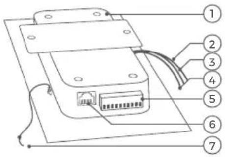
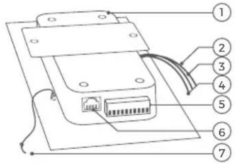
1) Main Electrical Unit
2) Yellow cable for call button
Connected to the illuminated call button with nameplate
3) Red cable for Module Port 1(unused)
4) Green cable for Module Port 2 (unused)
5) Screw connection terminal
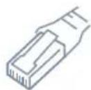
6) LAN/PoE jack
7) Nylon cord
To secure the front
panel during assembly
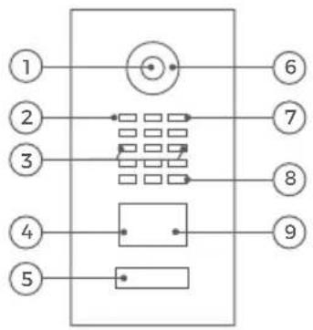
DEVICE EXAMPLE WITH 2 AND MORE CALL BUTTONS
Front
flowchart
graph TD
    1 --> A["Central Circle"]
    2 --> B["Grid Block"]
    3 --> B
    4 --> C["Rectangular Block"]
    5 --> D["Parallel Blocks"]
    6 --> E["Terminal 6"]
    7 --> F["Terminal 7"]
    8 --> G["Terminal 8"]
    9 --> H["Terminal 9"]
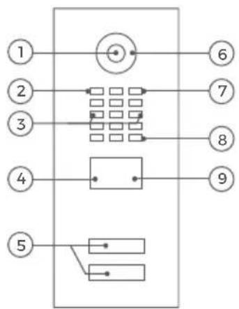
1) HDTV Video
2) Light Sensor For night vision mode
3) Security screws
4) Motion Sensor
5) Illuminated call buttons with nameplate The illumination is also acting as Diagnostic LED(s).
6) Night Vision LEDs
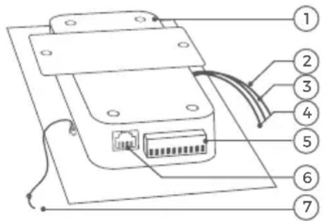
1) Main Electrical Unit
2) Velcro tape 1
To fix the Multi
Tenant Module
temporary on the
Main Electrical
Unit during assembly
3) Yellow cable for call button (unused)
4) Red cable for Module Port 1 Connected to Multi Tenant Module
5) Green cable for Module Port 2 (unused)
6) Screw connection terminal
7) LAN/PoE jack
8) Nylon cord
To secure the front
panel during assembly

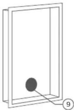
natural_image
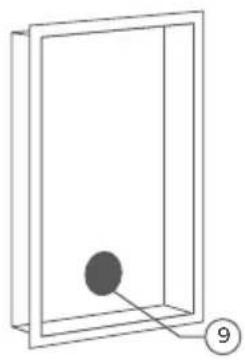
Simple line drawing of a rectangular frame with a central circular element and an arrow pointing to it, labeled with number 9 (no text or symbols on the diagram itself)9) Velcro tape 2 To fix the Multi Tenant Module permanently on the backbox

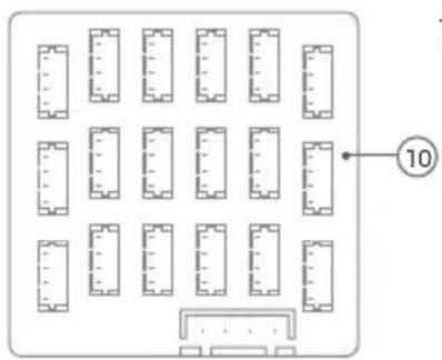
10) DoorBird Multi Tenant Module MTM18A
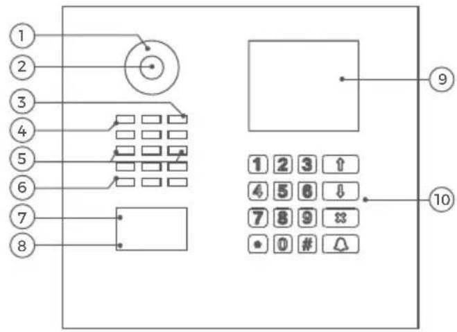
DEVICE EXAMPLE WITH DISPLAY MODULE AND KEYPAD MODULE
Front
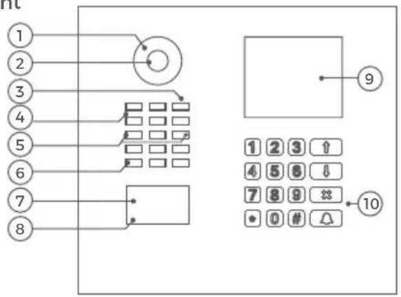
1) Night Vision LEDs
2) HDTV Video
3) Microphone
4) Light Sensor For night-vision mode
5) Security screws
6) Loudspeaker
7) RFID Reader
8) Motion Sensor
9) Display Module
10) Keypad Module The illumination is also acting as Diagnostic LED(s)
Inside

1) Main Electrical Unit
2) Yellow cable for call button (unused)
3) Red cable for Module Port 1 Connected to the Keypad Module
4) Green cable for Module Port 2 Connected to the Display Module
5) Screw connection terminal
6) LAN/PoE jack
7) Nylon cord
To secure the front
panel during assembly
DEVICE EXAMPLE WITH INFO MODULE AND KEYPAD MODULE
Front
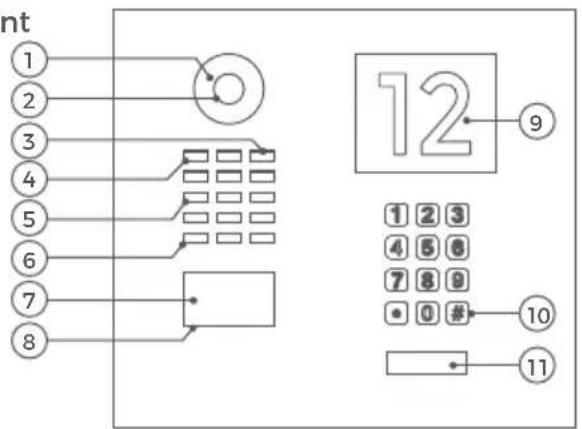
1) Night Vision LEDs
2) HDTV Video
3) Microphone
4) Light Sensor For night-vision mode
5) Security screws
6) Loudspeaker
7) RFID Reader
8) Motion Sensor
9) Info Module
10) Keypad Module The illumination is also acting as Diagnostic LED(s)
11) Illuminated call button with nameplate The illumination is also acting as Diagnostic LED(s).
Inside

VIDEOS
Need help with the installation? Be sure to watch our installation videos which can be found on http://www.doorbird.com/support
Each individual step of the installation is clearly documented in the videos.
INSTALLATION
All the steps below should be carried out carefully by a competent adult, taking into consideration any applicable safety regulations. Please contact us directly or seek the advice of a competent specialist.
Please ensure that all wires used for the installation are undamaged along their entire length and approved for this type of use.
Network speed and network components
Please ensure that the upload speed of your Internet connection is at least 0.5 Mbps. You can also carry out a speed test at any time via the DoorBird App. The user experience is only as good as your network speed, network stability and quality of your network components, such as your Internet Router and WiFi access points or WiFi repeaters. Please also make sure that your network components are no older than two years, have been manufactured by a well-known manufacturer, and have the latest firmware installed.
Should these requirements not be fulfilled, it may occur, for example that the performance of audio and video is poor or push notifications are delayed or do not arrive on your smartphone or tablet at all.
Requirements:
High-speed Internet (via landline): DSL, cable or optical fibre
Network: Ethernet, with DHCP
1) Main Electrical Unit
2) Yellow cable for call button (unused)
3) Red cable for Module Port 1 Connected to the Keypad Module
4) Green cable for Module Port 2 Connected to the Info Module
5) Screw connection terminal
6) LAN/PoE jack
7) Nylon cord To secure the front panel during assembly
1
SWITCHING OFF POWER

Switch off the power to all wires leading to the assembly location, i.e. the door chime, electric door opener, power supply unit for the video door station etc.
2
DISMANTLING THE EXISTING DOORBELL
Should there already be a doorbell or door station on the exterior wall of the house, please dismantle it.
3
DETERMINING THE ASSEMBLY LOCATION
The device uses an ultra wide-angle hemispheric lens so that even when the person is a minimum distance of 50 cm (19.68 in) away from the device, a low installation height is sufficient. The lens is therefore not mechanically adjustable. The camera lens should be located at an altitude of at least 145 cm (57 in). You may check this prior to the final mounting.
When choosing the assembly location, consider the lighting conditions. Avoid direct sunlight, direct backlight and reflective surfaces.
NOTICE
Do not expose the device to direct sunlight. The housing temperature can exceed the maximum allowed temperature limit. This can result in damage of electric and mechanic components of the device and injuries especially when touching exterior parts of the device. White and bright silver-colored front plates absorb less sunlight than dark ones.
NOTICE
An image sensor must not be exposed to direct sunlight for an extended period of time. Direct sunlight will “blind” the camera and may permanently bleach the small color filters on the image sensor chip.
!
Any defects caused by direct sunlight are not covered by warranty.
The network cable between the device and the PoE-Switch/PoE-Injector/Internet Router can have a maximum length of 80 meters/262 feet (IEEE 802.3).

If you have only two wires available at the assembly location, you may use of the "DoorBird 2-Wire Ethernet PoE Converter A1071", sold separately. It allows you to transfer network data (Ethernet) and power (PoE) with a simple two-wire cable over long distances. For example: existing buildings with a simple two-wire bell wire can be equipped with network technology without having to retrofit any network cables.
4
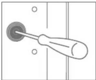
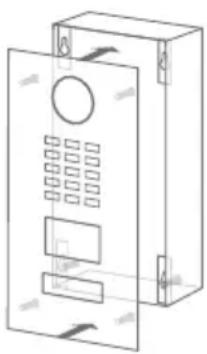
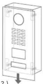
REMOVING THE FRONT PANEL
Remove the front panel carefully using the screw driver provided with the device from the mounting housing (backbox).
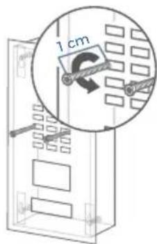
1.) Turn out the security screws for 1 cm
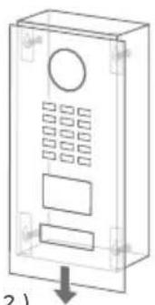
natural_image
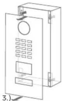
Diagram of a rectangular device with internal components and a downward arrow, no text or symbols presentPull down the front panel.

natural_image
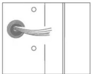
Technical line drawing of a door with control panel and door lock (no text or symbols)Pull the front panel towards you.
5
ASSEMBLING THE MOUNTING HOUSING
Assemble the mounting housing (backbox) to the wall. You can find detailed drawings and measurements of the device in the corresponding datasheet.

If you must drill holes in a wall, insert screws into a wall or lever up a wall, ensure that no cables or mains (gas, water, etc.) are to be found in the wall.
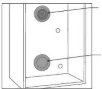
Mounting the surface-mounted housing
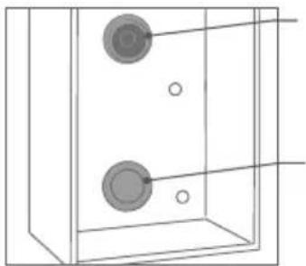
natural_image
Pure technical line drawing of a 3D rectangular enclosure with circular components and internal lines (no text or symbols)Rubber seal for cable entry
Cover for unused openings
Place the rubber seal for the cable entry on the mounting opening.
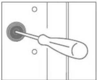
natural_image
Simple line drawing of a screwdriver with a circular head and handle, no text or symbols presentPierce through the middle of the rubber seal using a screwdriver.

natural_image
Pure diagram of a mechanical or electrical component with no text, numbers, or symbolsFeed all cables and wires that you want to connect to the device through the rubber seal.
6
POWER SUPPLY OPTIONS
The device can be powered using the DoorBird power-supply unit (mains adaptor) (Option 1) or via PoE (Power over Ethernet) using a network cable (Option 2). The device can be alternatively also be supplied with power using a DIN-rail power supply unit that you can obtain directly from us. The device does not use battery power.
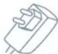
OPTION 1
Power supply using the power supply unit (mains adaptor)

The power supply unit (mains adaptor) has a 300 cm long cable with two insulated wires.
NOTICE
Do not plug the power supply unit into the wall socket yet. Only use the original DoorBird power supply unit or a DIN-rail power supply unit that you can obtain from us separately, since this has been specially stabilized electrically and is equipped with an integrated audio interference reduction device. Other power supply units may destroy the device or cause poor transmission quality. The warranty expires automatically if you use a different power supply unit.
OPTION 2
Power supply and network connection using PoE (Power over Ethernet)
To power the device via a PoE-Switch (e.g. D-Link DGS-1008P) or PoE-Injector (e.g. DoorBird Gigabit PoE Injector A1091) in accordance with the PoE standard IEEE 802.3af Mode A, the four wires bearing the numbers 1, 2, 3 and 6 of a Cat.5 cable or better are to be used. A Cat.5 cable or better must be used as network signals can only be transmitted over completely insulated, shielded and twisted cables. If you use PoE as a source of power the four wires for PoE then simultaneously form the data link. The device won't start if your PoE-Switch/PoE-Injector
does not support the PoE Standard IEEE 802.3af Mode A (see Diagnostic-LED and Diagnostic-Sounds).

- Disconnect the PoE-Switch or PoE-Injector from the power grid.
- Run the network cable to the installation location of the device.
7
CONNECTING THE DEVICE
It is possible to connect the cables and wires to the device conveniently and safely via labelled connection ports. You can connect all necessary cables and wires to the device now. Please remove any cables and wires from the connection ports of the device that you do not need. Remove about 5 mm of insulation material at the end of the wires that you would like to connect to the green screw connection terminal of the device.

Please take care when connecting the cables and wires. Connecting the cables and wires the wrong way may damage the device.
Wires without insolation material must not protrude out of the green screw connection terminal, it may lead to electrical short and damage the device.

The yellow, green, and red cables that lead out from the side of the Main Electrical Unit must only be used to connect components certified by Bird Home Automation.

Handle the front panel with care. The surface of the front panel could be scratched or otherwise damaged if handled without care.
You can use the nylon cord to temporary fix the front panel to the mounting housing (backbox) while connecting the cables and wires to the device.
natural_image
Pure technical line drawing of a mechanical assembly without any text, numbers, or symbols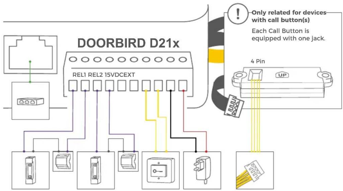
flowchart
graph TD
    A["DOORBIRD D21x"] --> B["REL1 REL2 15VDCEXT"]
    B --> C["Device 1"]
    B --> D["Device 2"]
    B --> E["Device 3"]
    B --> F["Device 4"]
    B --> G["Device 5"]
    B --> H["Device 6"]
    B --> I["Device 7"]
    B --> J["Device 8"]
    B --> K["Device 9"]
    B --> L["Device 10"]
    B --> M["Device 11"]
    B --> N["Device 12"]
    B --> O["Device 13"]
    B --> P["Device 14"]
    B --> Q["Device 15"]
    B --> R["Device 16"]
    B --> S["Device 17"]
    B --> T["Device 18"]
    B --> U["Device 19"]
    B --> V["Device 20"]
    B --> W["Device 21"]
    B --> X["Device 22"]
    B --> Y["Device 23"]
    B --> Z["Device 24"]
    B --> AA["Device 25"]
    B --> AB["Device 26"]
    B --> AC["Device 27"]
    B --> AD["Device 28"]
    B --> AE["Device 29"]
    B --> AF["Device 30"]
    B --> AG["Device 31"]
    B --> AH["Device 32"]
    B --> AI["Device 33"]
    B --> AJ["Device 34"]
    B --> AK["Device 35"]
    B --> AL["Device 36"]
    B --> AM["Device 37"]
    B --> AN["Device 38"]
    B --> AO["Device 39"]
    B --> AP["Device 40"]
    B --> AQ["Device 41"]
    B --> AR["Device 42"]
    B --> AS["Device 43"]
    B --> AT["Device 44"]
    B --> AU["Device 45"]
    B --> AV["Device 46"]
    B --> AW["Device 47"]
    B --> AX["Device 48"]
    B --> AY["Device 49"]
    B --> AZ["Device 50"]
    style DOORBIRD_D21x fill:#f9f,stroke:#333
    style DOORBIRD_D21x fill:#ccf,stroke:#333
    note right of DOORBIRD_D21x: Only related for devices with call button(s)
Each Call Button is equipped with one jack.
4 Pin: Only related for devices with call button(s)
Each Call Button is equipped with one jack.
4 Pin: Only related for devices with call button(s)
Each Call Button is equipped with one jack.
4 Pin: Only related for devices with call button(s)
Each Call Button is equipped with one jack.
4 Pin: Only related for devices with call button(s)
Each Call Button is equipped with one jack.
4 Pin: Only related for devices with call button(s)
Each Call Button is equipped
Each Call Button is equipped with one jack.
4 Pin: Only related for devices with call button(s)
Each Call Button is equipped with one jack.
4 Pin: Only related for devices with call button(s)
Each Call Button is equipped with one jack.
4 Pin: Only related for devices with call button(s)
Each Call Button is equipped with one jack.
4 Pin: Only related for devices with call button(s)
Each Call Button is equipped with one jack.
4 Pin: Only related for Devices
Each Call Button is equipped with one jack.
4 Pin: Only related for Devices
Each Call Button is equipped with one jack.
4 Pin: Only related for Devices
Each Call Button is equipped with one jack.
4 Pin: Only related for Devices
Each Call Button is equipped with one jack.
4 Pin: Only related for Devices
Each Call Button is equipped with one jack.
4 Pin: Only related for Devices
Each Call Button is equipped with one jack.
4 Pin: Only related to Device
Each Call Button is equipped with one jack.
4 Pin: Only related to Device
Each Call Button is equipped with one jack.
4 Pin: Only related to Device
Each Call Button is equipped with one jack.
4 Pin: Only related to Device
Each Call Button is equipped with one jack.
4 Pin: Only related to Device
Each Call Button is equipped with one jack.
4 Pin: Only related to Device
Each Call Button is equipped with one jack.
4 Pin: Only related to Device
Each Call Button is equipped to one jack.
4 Pin: Only related to Device
Each Call Button is equipped to one jack.
4 Pin: Only related to Device
Each Call Button is equipped to one jack.
4 Pin: Only related to Device
Each Call Button is equipped to one jack.
4 Pin: Only related to Device
Each Call Button is equipped to one jack.
4 Pin: Only related to Device
Each Call Button is equipped to one jack.
4 Pin: Only related (up) or (down) connection
PORT DESCRIPTION
| LAN/POE RJ45 jack to connect a standard Network cable Cat.5 or better, coming from the Internet Router/PoE-Switch/PoE-Injector.NOTICEDo not power the device simultaneously via the power supply from the power supply unit (mains adaptor) and the power supply via PoE. | |
| REL1, REL1 | Bi-stable latching relay #1, max. 24 V DC/AC, 1 Ampere. Security feature: The relay keeps its state even in the case of loss of power. You can configure the default state of the relay (open/close) via the DoorBird App. These ports can be used to connect e.g. an electric door opener. The device does not supply power to the connected device. The power supply for the electric door opener must be installed separately.When wiring an electric door opener directly to a door station, there is a risk that the electric door opener could be tampered by unauthorized third parties (e. g. by breaking the door station and short-circuiting the wiring of the door opener). Therefore, we generally recommend the use of a remote safety relay mounted indoors (e. g. DoorBird I/O Door Controller A1081) for wiring an electric door opener for a more secure installation in your home. |
| REL2, REL2 | Bi-stable latching relay #2, max. 24 V DC/AC, 1 Ampere. Security feature: The relay keeps its state even in the case of loss of power. You can configure the default state of the relay (open/close) via the DoorBird App. These ports can be used to connect e.g. an electric door opener. The device does not supply power to the connected device. The power supply for the electric door opener must be installed separately.When wiring an electric door opener directly to a Door station, there is a risk that the electric door opener could be tampered by unauthorized third parties (e. g. by breaking the door station and short-circuiting the wiring of the door opener). Therefore, we generally recommend the use of a remote safety relay mounted indoors (e. g. DoorBird I/O Door Controller A1081) for wiring an electric door opener for a more secure installation in your home. |
| BELL, BELL | NOTICEReserved - Do not use! |
| EXT, EXT | Door opener button, max. 0 V DC/AC, 0 Ampere. These ports can be used to connect e.g. a door opener button inside the home. It will trigger the first bi-stable latching relay of the device (REL1, REL1).NOTICEPlease make sure to add no voltage on these ports. Extra voltage may destroy the device immediately. |
| 15 VDC - | 15 V DC Power supply input, negative pole (-). Please connect the black wire of the DoorBird power supply unit (mains adaptor) here, if you do not power the device using PoE.NOTICEDo not power the device simultaneously via the power supply from the power supply unit (mains adaptor) and the power supply via PoE. |
| 15 VDC + 15 V DC Power supply input, positive pole (+). Please connect the red wire of the DoorBird power supply unit (mains adaptor) here, if you do not power the device using PoE.NOTICEDo not power the device simultaneously via the power supply from the power supply unit (mains adaptor) and the power supply via PoE. | |
| Only related for devices with call button(s): | |
| 4 PIN (SWITCH) | Use the yellow cable to connect the button to the IP Video Door Station. |

Please take care when connecting the cables and wires. Connecting the cables and wires the wrong way may damage the device. Wires without insolation material must not protrude out of the green screw connection terminal, it may lead to electrical short and damage the device.
8
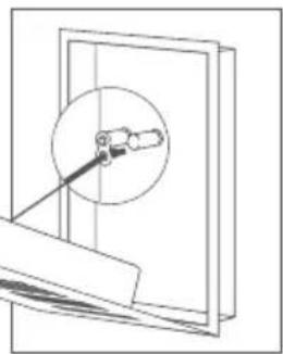
ASSEMBLING THE FRONT PANEL
Assemble the front panel of the device to the mounting housing (backbox) of the device.
natural_image
Technical line drawing of a rectangular electronic device with internal components and mounting holes (no text or symbols)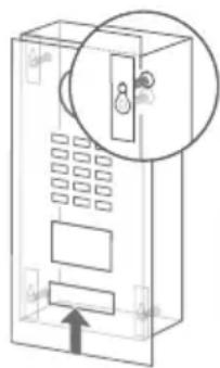
natural_image
Technical line drawing of a cabinet or enclosure with a magnified inset showing a lock and door (no text or symbols)
natural_image
Technical line drawing of a cabinet with internal components and a magnified inset showing a mechanical component (no text or symbols)1.) Pull the front panel into the mounting housing (backbox)
2.) Push the front panel up.
3.) Insert the security screws.
9
ACTIVATING THE DEVICE
Switch on the power leading to the assembly location again. If you use PoE, make sure to switch on power of the PoE-Switch or PoE-Injector you have connected the device to.

Do not power the device simultaneously via the power supply from the power supply unit (mains adaptor) and the power supply via PoE.
You can see if the device is powered by checking the Diagnostic-LED, which lights up after about 30 to 60 seconds after the power is connected. The device is ready for operation (booting up process, any software updates, etc.) once it has emitted a short diagnosis sound from the integrated loudspeaker. This may last for up to 5 minutes. If the Diagnostic LED does not light up, please check the power supply. Please also check whether you have used a wall-plug power supply and not PoE and whether you have connected the positive pole and negative pole to the device correctly.
10
DOWNLOADING AND INSTALLING THE APP
Download the "DoorBird" App by Bird Home Automation onto your mobile device from the Apple App Store or Google Play Store. You can always find the most up-to-date version of the App manual on www.doorbird.com/support
Go to DoorBird App "Settings > Add device" and click on the QR code icon in the "User" field. Scan the user QR code found on the "Digital Passport" provided with the device.
If you have problems adding the device to the App, please check if the device is online (www.doorbird.com/checkonline). If the device is not online, please check the network connection and the power supply of the device.
DIAGNOSTIC-LED
You can see if the device is powered by checking the Diagnostic-LED, which lights up after about 30 to 60 seconds after the power is connected.
DIAGNOSTIC-SOUNDS
After around one to five minutes, the device emits brief diagnostic sounds after it has been connected to the power grid.
MOTION SENSOR
The device has a built-in Motion Sensor with 4D Technology. You can use it for numerous applications, e.g. to send an alarm to a mobile device or to switch a relay to turn on an outdoor light.
RFID READER
The built-in RFID reader can be used for many applications, e.g. to open/lock doors or arming/disarming your alarm system. For security reasons, the RFID reader has a very short range (0 - 3 cm, 0 - 1.18 in), so you must place the compatible RFID tag (key fob) very close to the RFID reader. You can configure the RFID reader using the DoorBird App.

The RFID reader works only on short distance, for security reasons.
API
The device features a well documented API for third-party integration. For information, terms and conditions see www.doorbird.com/api
DOORBIRD CONNECT
The device features many options to integrate it into third-party applications. For information, terms and conditions see www.doorbird.com/connect
CHANGING THE LABEL OF A CALL BUTTON NAMEPLATE
Applies only to devices with 1 and more illuminated call buttons with nameplate.
Engraving Service

Engraving service for a modern and clean appearance: www.doorbird.com/engraving

Please follow STEP 1 to switch off power. We recommend to use a thin slot screwdriver to remove the cover of the nameplate. We recommend to use white paper for the label which does not absorb moisture.
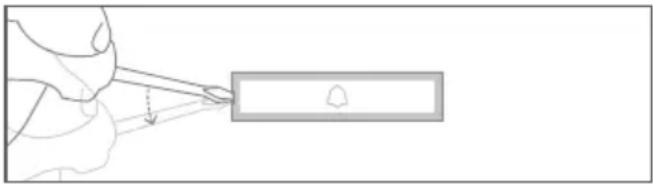
natural_image
Line drawing of a hand holding a small object with a bell icon, no text or symbols present
natural_image
Simple 3D diagram of a rectangular object with a curved top edge and a small circular mark on the side (no text or symbols)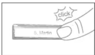
CHANGING THE LABEL OF THE INFO MODULE

Applies only to devices with Info Module.
Please follow STEP 1 to switch off power and STEP 2 to open the device. You can then change the labeling of the Info Module in the inside. We recommend to use white paper for the label which does not absorb moisture.
CONNECTING CALL BUTTONS TO THE MULTI TENANT MODULE

Applies only to devices with 2 and more illuminated call buttons with nameplate.
Connect only call buttons to the Multi Tenant Module (e.g. Multi Tenant Module MTM18A) certified by Bird Home Automation.
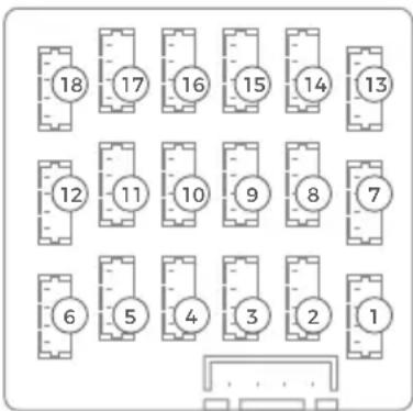
① = 1. call button jack ⑱ = 18. call button jack
MAINTENANCE FOR DOORBIRD PRODUCTS
Cleaning and maintenance instructions
All DoorBird door stations are made of high-quality materials and are designed for a durable lifetime. Since door stations are usually installed in unprotected outdoor areas, they are exposed to adverse weather conditions and aggressive substances, especially close to frequently used roads, in coastal and industrial areas. Therefore please consider the following care instructions. Unfortunately, we cannot accept any liability for damage if these instructions are not being observed.
Aggressive dirt such as bird droppings should be removed as quickly as possible.

Never use abrasive detergents such as steel wool or scouring milk!
Warm water is usually sufficient, if necessary with a little detergent, a soft cloth or brush. Plastic parts (camera or name tags) must not be treated with metal care products. Remove all residues of cleaning agents or lubricants to avoid stains or discolouration after the maintenance.
Stainless Steel
Only high-quality German stainless steel is used for all available DoorBird door stations. However, high-quality stainless steel can also rust, as approx. 70% of stainless steel is made of iron. Rust resistance is only achieved by a protective layer (also called passive layer), which covers the iron like a skin. This protective layer consists essentially of chromium and other precious metals.
Iron particles, grinding dust and chips deposited on stainless steel can lead to corrosion (rust film). These
iron particles can be found everywhere, but especially in coastal and industrial areas and close to frequently used roads. Please remove ferrous deposits immediately, as they will attack your door station and lead to real rust if not removed. To remove rust, simply wipe off the dust; in addition, a care product is recommended, e.g. WD 40, available e.g. at Amazon for less than € 5.00. Simply apply in a thin layer and rub in. The same applies if rust appears on the engravings on the stainless steel surface.
Cement or lime splashes should be carefully removed as soon as possible with a wooden spatula before hardening.
The following cleaning detergents are not to be used as they reduce corrosion resistance:
- products containing chloride and hydrochloric acid
- Bleach (in case of accidental use, rinse thoroughly with water)
- Silver polish
After the cleaning with clear water wipe with damp cloth and rub dry to avoid lime traces. Lime residues can be avoided by using demineralised water.
Stainless steel PVD coated
PVD coated, chrome-plated or gold-plated surfaces are recommended to be cleaned with a grease-dissolving detergent and clear water or with a clean and dust-free microfibre cloth. For high-gloss surfaces, use a scratch-free cloth (e.g. cleaning cloth for glasses, furniture polishing cloth, etc.).
Lacquered surfaces
Clean painted surfaces and lettering with a soft, scratch-free cloth moistened with a mild soap solution (e.g. cleaning cloth for glasses, furniture polishing cloth, etc.). To prevent stains or discolouration, the detergents should be wiped off without leaving any residue. Be particularly careful with lettering in order not to damage the film or the print.
TECHNICAL SPECIFICATIONS
| GENERAL | |
| Power supply | 15 V DC (max. 15 W) or Power over Ethernet (PoE 802.3af Mode-A) |
| Info Module* | 3.5", illuminated |
| Display Module* | 3.5" LCD (no touch function), illuminated, for the display of a 2-line free text and the name directory (max. 100 entries) |
| Keypad Module* | 16 keys, illuminated, configurable via App. e.g.Individual PIN codesIndividual events (e.g. switch a relay, push notification, SIP call [audio/video], HTTP(s) request)Individual schedulesUp to 100 PIN codes manageable |
| Connectors | RJ45, for LAN/PoEBi-stable latching relay #1, max. 24 V DC/AC, 1 Ampere, e.g. for electric door openerBi-stable latching relay #2, max. 24 V DC/AC, 1 A, e.g. for electric door openerExternal input for external door opener button (potential-free)15 V DC input (+,-), max. 15 WRelays can be expanded / detached with DoorBird I/O Door Controller |
| Weather-proof | Yes, IP65 |
| Approvals | IP65, CE, FCC, IC, RoHS, IK08, REACH, IEC/EN 62368, IEC/EN 62471 |
| Operating conditions | -25 to +55°C / -13 to 131°FHumidity 10 to 85 % RH (non-condensing) |
| Scope of delivery | 1x Main Electrical Unit1x Front panel*(110 - 240 V AC to 15 V DC)1x RFID key fob1x Screwdriver1x Quickstart guide with Digital Passport1x Installation manual1x Small parts |
| Warranty | see www.doorbird.com/warranty |
CURRENT SYSTEM REQUIREMENTS
| System requirements | Mobile device: Newest iOS on iPhone/iPad, newest Android on Smartphone/TabletInternet: High-Speed Landline Broadband Internet connection, DSL, cable or fiber optic, no socks or proxy serverNetwork: Ethernet Network, with DHCP |
| Recommended installation height | Camera lens should be at a min. height of 145 cm (57 in). Before the installation please determine your optimal installation height. |
VIDEO
| Camera | HDTV 720p, dynamic (VGA - HDTV) |
| Lens | High-end ultra wide-angle hemispheric lens 180^ (D), 140^ (H), 100^ (V), straightened, IR-capable |
| Night-vision | Yes, light sensor, automatic IR-cut filter, 12 Infrared LEDs (850 nm) |
AUDIO
| Audio components | Speaker and microphone, noise reduction and echo cancellation (ANR, AEC) |
| Audio streaming | Two-way, full duplex |
NETWORK
| Ethernet | RJ45 jack, PoE 802.3af Mode-A, 10/100 Base-T |
| Supported protocols | HTTP, HTTPS, SSL/TLS, Bonjour, DNS, RTSP, RTP, TCP, UDP, RTCP, ICMP, DHCP, ARP, SIP, DTMF (RTP [RFC-2833], SIP INFO [RFC-2976]), STM |
MOTION SENSOR
| Type | Active |
| Detection angle | 54° (H), 70° (V) |
| Range | 1 - 10 m (3.3 - 32.9 ft), depends on environment, configurable in 1 m (3.3 ft) steps.If a “Display Module” is connected to the Main Electrical Unit, the range is limited to 1 m (3.3 ft). |
| Technology | 4D. Based on multiple integrated sensors and algorithms, e.g. Radio Frequency Energy (RFE)Via App, e.g.Range (1 - 10 m / 3.3 - 32.9 ft)Movement direction (coming, leaving, both)Individual events (e.g. switch a relay, push notification, SIP call [audio/video], HTTP(s) notification)Individual schedules |
| Configuration |
RFID
| Type | Active Reader Passive Tag (ARPT) system |
| Standard | ISO/IEC 18000-2:2009 Part 2, EM4100, EM4102 |
| Frequency | 125 KHz |
| Range | 0 - 3 cm, depends on environment |
| Antenna | Internal |
| Compatible Transponder | RFID key fobs, sold separately, see www.doorbird.com/buyUp to 100 tags manageable |
| Configuration | Via App, e.g. Tag (add, delete)Individual events (e.g. switch a relay, SIP call [audio/video], HTTP(s) notification)Individual schedules |
INTEGRATED WIRELESS MODULES
| RFID | 125 KHz |
| Sensor | 24 GHz, can be disabled |
THIRD-PARTY INTEGRATION (DOORBIRD CONNECT)
| Partnerintegrations | see www.doorbird.com/connect |
| API see www.doorbird.com/api | |
| Simultaneous video streams | One, for event-based and continuous recording |
OPTIONAL ACCESSORIES
| Sold separately | see www.doorbird.com/buy |
Errors and omissions excepted.
LEGAL NOTES
General remarks
- DoorBird is a registered trademark of Bird Home Automation GmbH.
- Apple, the Apple logo, Mac, Mac OS, Macintosh, iPad, Multi-Touch, iOS, iPhone and iPod touch are trademarks of Apple Inc.
- Google, Android and Google Play are trademarks of Google, Inc.
- The Bluetooth® word mark and logos are registered trademarks of Bluetooth SIC, Inc.
- All other company and product names may be trademarks of the respective companies with which they are associated.
- We reserve the right to make changes to our products in the interests of technical advancement. The products shown may also look different from the products supplied based on ongoing enhancement.
- Reproducing or using texts, illustrations and photos from this instruction manual in any media - even if only in the form of excerpts - shall only be permitted with our express written consent.
- The design of this manual is subject to copyright protection. We do not accept any liability for any errors or any erroneous content or printing errors (even in the case of technical specifications or within graphics and technical sketches).
- Our products are in compliance with all technical guidelines, electrical and telecommunications regulations applicable in Germany, the EU and the USA.
- Our products and also the components contained therein (ICs, software, etc.) may only be used for civilian non-military purposes.
Data privacy and data security
- For maximum security, the device uses the same encryption technologies as are used in online banking. For your security, no port forwarding or DynDNS is used either.
- The data centre location for remote access over the Internet by means of an App is obligatory in the EU if the determined Internet IP-Address location of the device is within the EU. The data centre is operated in line with the most stringent security standards.
- Video, audio and any other surveillance methods can be regulated by laws that vary from country to country. Check the laws in your local region before installing and using this device for surveillance purposes.
If the device is a door-, indoor station or camera:
- In many countries video and voice signal may only be transmitted once a visitor has rung the bell (data privacy, configurable in the App).
- Please carry out the mounting in such a way that the detection range of the camera limits the device exclusively to the immediate entrance area.
- The device may come with a visitor history and motion sensor. You can activate/deactivate this function if required.
If necessary, indicate the presence of the device in a suitable place and in a suitable form.
Please observe any relevant country-specific statutory regulations concerning the use of surveillance components and surveillance cameras applicable at the installation site.
Check with the property owner and your house community if you are allowed to install and use this product. Bird Home Automation GmbH cannot be held responsible for any miss-use or miss-configuration of this product, including the unauthorized opening of a door.
Bird Home Automation cannot be held responsible for damages caused by improper existing installations or improper installation.
Software and operating system's updates (so-called "firmware updates") are generally automatically installed on the products of Bird Home Automation GmbH via Internet, if technically possible. Automatic firmware updates keep the products' software up to date so that they always work reliably, safely and efficiently. Through further development, features can be added, extended or slightly changed. Major changes or limitations to existing features will generally occur if Bird Home Automation GmbH deems it necessary (e.g. for data protection, data security or stability reasons, or to keep them up to date). When a firmware update is available, Bird Home Automation GmbH's servers generally automatically distribute it to all compatible products connected to the Internet or Bird Home Automation GmbH's servers. This process is gradual and can take several weeks. As soon as a product receives a firmware update, the system will be installed and will restart by itself. Installed firmware updates cannot be undone. Since the products and software of Bird Home Automation GmbH are not explicitly customer-specific products, a customer cannot deny an automatic update if the product is connected to the Internet or to the Bird Home Automation GmbH's server.
Publisher
It is possible that these manual still contains typographical errors or printing errors. The information in this manual will be checked regularly and corrections will be made in the next version. We accept no liability for errors of a technical or printing nature and their consequences.
natural_image
Simple line drawing of a rectangular frame with a central circular element and an arrow pointing to it, labeled with number 9 (no text or symbols on the diagram itself)
natural_image
Simple line drawing of a container with two circular components and three empty circles, no text or symbols present.natural_image
Simple line drawing of a screwdriver inserted into a circular component (no text or symbols)natural_image
Pure diagram of a coiled cable or wire inside a circular component, without any text, numbers, or symbols.natural_image
Technical line drawing of a mechanical assembly with a circular component and diagonal tool (no text or symbols)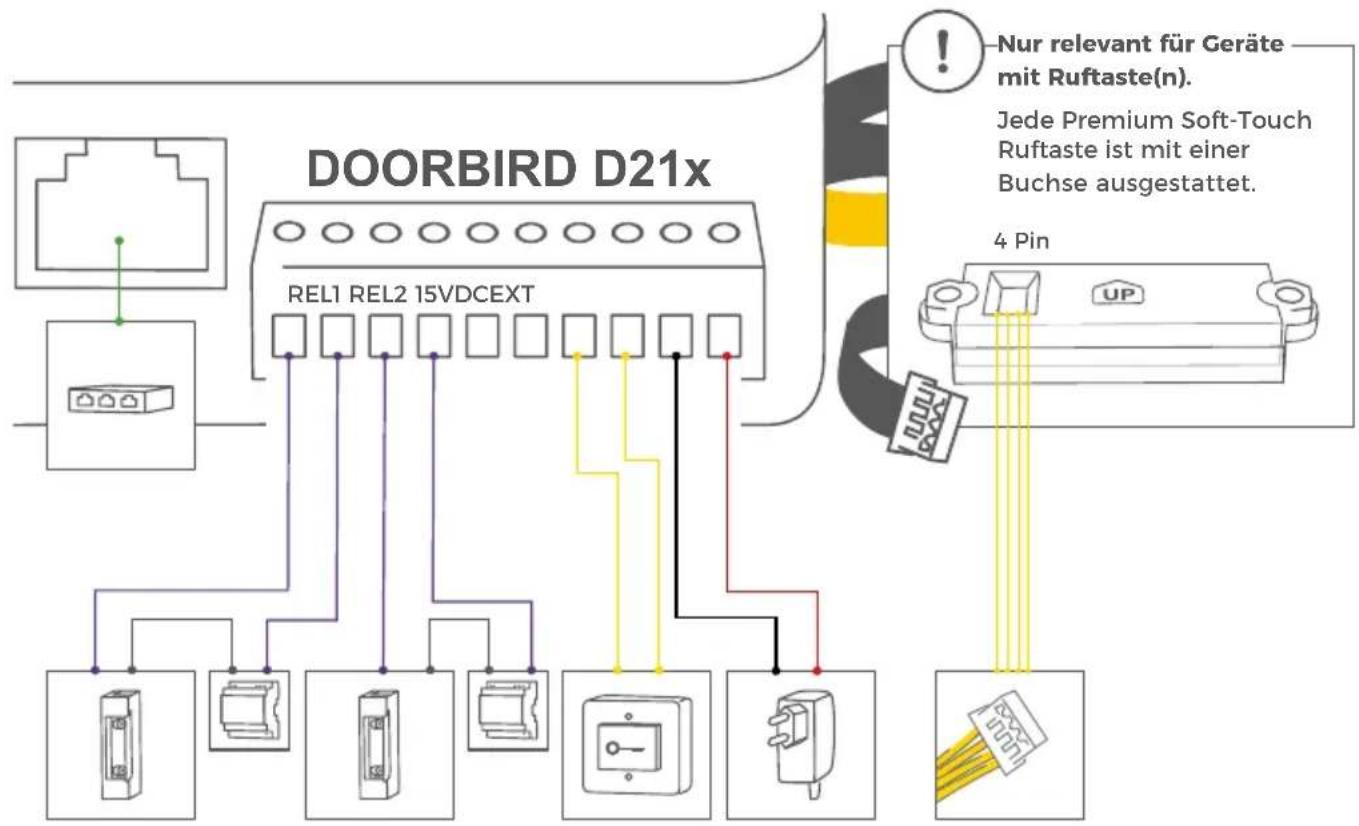
natural_image
Technical line drawing of a rectangular electronic device with internal components and mounting holes (no text or symbols)natural_image
Diagram of a server rack with a lock and door, showing internal compartments and a close-up view (no text or symbols)natural_image
Technical line drawing of a mechanical device with an inset showing a close-up of a tool interacting with a grid-patterned component (no text or symbols present)natural_image
Line drawing of a hand holding a tool with a small bell icon, no text or symbols present
natural_image
Simple 3D diagram of a mechanical component with no text or symbols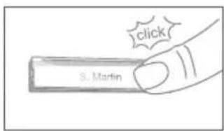
MANUEL D'INSTALLATION
natural_image
Simple line drawing of a rectangular frame with a central circular element and an arrow pointing to it, labeled with number 9 (no text or symbols on the diagram itself)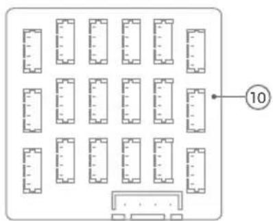
natural_image
Simple line drawing of a rectangular container with two circular components and a connecting rod (no text or symbols)natural_image
Simple line drawing of a screwdriver with a circular head and mounting holes (no text or symbols)natural_image
Pure technical line drawing of a mechanical assembly without any text, numbers, or symbols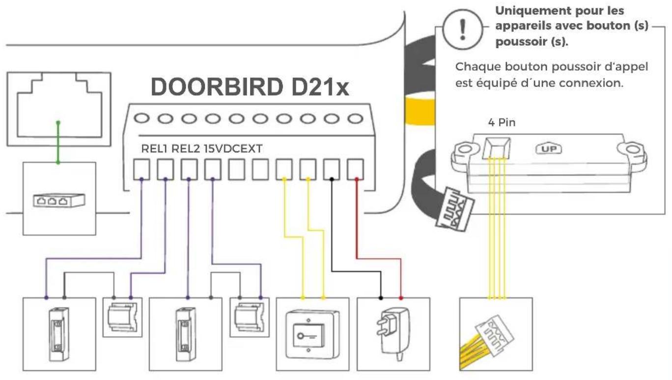
natural_image
Three technical diagrams showing a door panel installation, a close-up of the door lock mechanism, and a grid-patterned panel with arrows indicating rotation (no text or symbols present)natural_image
Line drawing of a hand holding a rectangular object with a small bell icon, no text or symbols present
natural_image
Simple 3D illustration of a rectangular block with a curved cutout, no text or symbols present
CONNECTER LES BOUTONS D'APPEL AU MODULE MULTI-RÉSIDENTIEL

EJEMPLO DE DISPOSITIVO CON MÓDULO DE DISPLAY Y MÓDULO DE TECLADO
Frontal
natural_image
Isometric line drawing of a rectangular device with internal compartments and a circular top (no text or symbols)natural_image
Technical line drawing of a rectangular electronic device with internal components and mounting holes (no text or symbols)natural_image
Simple line drawing of a container with two circular components and connecting rods (no text or symbols)natural_image
Simple line drawing of a screwdriver with a circular head and handle (no text or symbols)natural_image
Pure diagram of a circular object with internal curved lines and a small circle, no text or symbols present.natural_image
Technical line drawing of a mechanical assembly with a magnified inset showing a cylindrical component (no text or symbols)
natural_image
Three technical line drawings of a server rack unit with internal components and a close-up inset showing the lock mechanism (no text or symbols)EU DECLARATION OF CONFORMITY (DoC)
We, Bird Home Automation GmbH, declare under our sole responsibility that the above referenced product complies with the following:
The CE symbol confirms that this product conforms with the above mentioned norms and regulations.
Conformity was assessed with the aid of the accessories/components that were included with delivery and described in the manual, including the current software officially approved for release. If other accessories/components are used, or current operating software not officially approved for release by Bird Home Automation GmbH, conformity with the above mentioned directives cannot be guaranteed.
This declaration is submitted by:
Berlin, December 18 ^th 2020
IP Video Door Station
D21x Series

Seite 16-30
VERSION 2.5, MIN. HW 1.71
INSTALLATION MANUAL
Read these instructions carefully before starting to use any components. Keep the manual so you can refer to it at a later date if required. If you hand over the device to other persons for use, please hand over the operating manual as well.
You can always find the most up-to-date version of the installation manual on www.doorbird.com/support
To make things easier we use the term “device” for the product “IP Video Door Station” and “mobile device” for a smartphone or tablet.
Liability
Every care has been taken in the preparation of this document. Please inform Bird Home Automation GmbH of any inaccuracies or omissions. Bird Home Automation GmbH cannot be held responsible for any technical or typographical errors and reserves the right to make changes to the product and manuals without prior notice. Bird Home Automation GmbH makes no warranty of any kind with regard to the content of this document, including, but not limited to, the implied warranties of merchantability and fitness for a particular purpose. Bird Home Automation GmbH shall neither be liable nor responsible for incidental or consequential damages in connection with the furnishing, performance or use of this material. This product is only to be used for its intended purpose.
Equipment Modifications
This equipment must be installed and used in strict accordance with the instructions given in the user documentation. This equipment contains no components that require service by the user. Unauthorized equipment changes or modifications will invalidate all applicable regulatory certifications and approvals.
Symbols used

Danger: Indicates a hazardous situation which, if not avoided, will result in death or serious injury.

Warning: Indicates a hazardous situation which, if not avoided, could result in death or serious injury.

Caution: Indicates a hazardous situation which, if not avoided, could result in minor or moderate injury.

Notice: Indicates a situation which, if not avoided, could result in damage to property.

Important: Indicates significant information which is essential for the product to function correctly.

Note: Indicates useful information which helps in getting the most out of the product.
Hazard information

WARNING
- Mounting, installation and servicing work on electrical devices may only be performed by a qualified electrician. Failure to observe this regulation could result in the risk of serious damage to health or fatal injury due to electric shocks.
- Devices with 110-240 V connection: The device may only be connected to an easily accessible power socket outlet. The mains adapter must be pulled out if a hazard occurs.
- For power supply, only use the original plugin mains adapter delivered with the device or a recommended PoE-Switch/PoE-Injector as specified in this manual.
- Because of electrostatic charging, direct contact with the circuit board can result in destruction of the device. Direct contact with the circuit board must therefore be avoided at any time.
- Observe the EN 60065 resp. EN 60950 resp. EN 62368 standard.
- Do not use the device if there are signs of damage to the housing, control elements or connecting sockets, for example, or if it demonstrates a malfunction. If you have any doubts, please have the device checked by an authorized expert.
- Do not open the device. This voids the warranty of the device. The device does not contain any parts that can be maintained by the user. In the event of an error, please have the device checked by an authorized expert.
- For safety, approval and licensing reasons (CE/FCC/IC etc.), unauthorized change and/or modification of the device is not permitted.
- The device is not a toy; do not allow children to play with it. Do not leave packaging material lying around. Plastic films/bags, pieces of polystyrene, etc. can be dangerous in the hands of a child.
• Always lay cables in such a way that they do not become a risk to people and domestic animals. - Voltage is applied to parts within the equipment. Do not touch any parts that are not associated with the installation, wiring, or connection. Electric shock could result.
- On devices which are not marked as weather-proof: Keep the device away from water or any other liquid.
- Do not install or make any wire terminations while power supply is plugged in. It can cause eletric shock or damage to the device.

WARNING
- Before turning on power, make sure wires are not crossed or shorted. If not, fire or eletric shock could result.
- High voltage may be present internally. Do not open the device. Electric shock could result.
- The device is not of explosion-proof. Do not install or use near gases or flammable materials. Fire or explosion could result.
- Do not install two power supplies in parallel to a single input. Fire or damage to the device could result. Be sure to connect a single power supply to the device.
- Do not connect any terminal on the device to an AC power line. Fire or electric shock could result.
- Keep AC cord from being marred or crushed. If the AC cord is fractured, fire or electric shock could result.
- Do not plug or unplug with wet hands. Electric shock could result.
- Do not put any metal or flammable material into the device. Fire, electric shock, or device trouble could result.
- Existing wiring may contain high voltage AC electricity. Damage to the device or electric shock could result. Wiring and installation must be done by a qualified elettrician.
- When mounting the device on a wall or ceiling, install the device in a convenient location, but not where it could be jarred or bumped. Injury could result.
- On devices with ground terminals, connect to an earth ground. Otherwise fire or malfunction could result.
- On devices with plastic or real glass, do not put high pressure on the glass. If fractured, injury could result.
- On devices with LCD, if LCD is punctured, do not allow contact with the liquid crystal inside. Injury could result. If necessary, gargle your mouth and clean your eyes or skin with clear water for at least 15 minutes and consult your doctor.
- Do not put anything on the device or cover the device with cloth, silicone, glue, coating, separate covering etc. Fire or device issues could result.
- Do not install the device in any of the following locations. Fire, electric shock, or device trouble could result.
- Places under direct sunlight or places near heating equipment that varies in temperature.
- Places subject to dust, oil, chemicals, hydrogen sulfide (hot spring).
-
Places subject to moisture and humidity extremes, such as bathrooms, cellars, greenhouses, etc.
-
Places where the temperature is very low, such as inside a refrigerated area or in front of an air conditioner.
- Places subject to steam or smoke (e.g. near heating or cooking surfaces).
- Where noise generating devices such as dimmer switches or inverter electrical appliances are closeby.
- Locations subject to frequent vibration or impact.
- On devices with intercom, be sure to perform a call test with low audio volume on both intercom devices. A sudden call etc. may arrive causing for example damage to your ear.
- If the device does not operate properly, unplug the power supply.
- All devices which are not marked as weatherproof are designed for indoor use only. Do not use outdoor.
- On devices which are marked weather-proof: Do not spray with high-pressure water. Device issues could result.
- We do not assume any liability for damage to property or personal injury caused by improper use or the failure to observe the
- hazard information. In such cases, any claim under warranty ceases. For consequential damages, we assume no liability!
Safety instructions
NOTICE
- The device shall be used in compliance with local laws and regulations.
- Store the device in a dry and ventilated environment.
- Avoid exposing the device to shocks or heavy pressure.
- Do not install the device on unstable brackets, surfaces or walls. Make sure the material is strong enough to support the weight of the device.
- Use only applicable tools when installing the device. Using excessive force with tools could cause damage to the device.
- Do not use chemicals, caustic agents, or aerosol cleaners.
- Use a clean dry cloth for cleaning.
- Use only accessories that comply with technical specification of the device. These can be provided by Bird Home Automation GmbH.
- Use only spare parts provided by or recommended by Bird Home Automation GmbH.
- Do not attempt to repair the device by yourself. Contact Bird Home Automation GmbH for service matters.
-
Keep the device more than 1 m (3.3') away from microwave, radio, TV, wireless router and any other wireless devices.
-
On devices with intercom or built-in speaker or built-in microphone or signal transmission functions, keep the wires more than 30 cm (12") away from AC 100-240 V wiring. AC induced noise and/or device malfunction could result.
- Install the device in an area that will be accessible for future inspections, repairs and maintenance.
- If the device is used close to a cellular phone, the device may malfunction.
- The device can be damaged if dropped. Handle with care.
- The device turns inoperative during power failure.
- On devices with intercom or built-in speaker or built-in microphone, in areas where cellular or Radio / TV broadcasting station antennas are closeby, the device may be affected by radio frequency interference.
- On devices with LCD screen, it must be noted in advance that the LCD panel, though manufactured with very high precision techniques, inevitably will have a very small portion of its picture elements always lit or not lit at all. This is not considered a device malfunction.
- On devices with intercom, due to the environmental sound around the device, it may hinder smooth communication, but this is not a malfunction.
- On devices with Username/Password, the Username/Password to access the device is the customer's responsibility. Make sure to use a password that cannot be easily guessed by a third party. We recommend that you change the Password on a regular basis.
• We will, under no circumstances, be liable for damage that occurs due to failures in power supply, network equipment or terminal devices; failures due to Internet providers and cellular network providers; failures such as disconnected lines and other losses in communication, which makes it impossible to provide this service as well as in any way delay this service due to any other causes outside of our responsibility; or if an error or missing data occurs during transmission.

Information on disposal for users of waste electrical & electronic equipment (private household)
This symbol on the products and/or accompanying documents means that used electrical and electronic products should not be mixed with general household waste. For proper treatment, recovery and recycling, please take these products to designated collection points, where they will be accepted an a free of charge basis. Alternatively, in some countries you may be able to return your products to your local retailer upon the purchase of an equivalent new product. Disposing of this product correctly will help to save valuable resources and prevent any potential negative effects on human health and the environment which could otherwise arise from inappropriate waste handling. Please contact your local authority for further details of your nearest designated collection point. Penalties may be applicable for incorrect disposal of this waste, in accordance with national legislation.
Information on disposal in other countries outside the European Union
This symbol is only valid in the European Union. If you wish to discard this product, please contact your local authorities or dealer and ask for the correct method of disposal.
Transportation

When transporting the device, use the original packaging or equivalent to prevent damage to the device.
Warranty Information
For information about the device warranty, see www.doorbird.com/warranty
Front
INSIDE

1) HDTV Video
2) Light Sensor For night vision mode
3) Security screws
4) Motion Sensor
5) Illuminated call button with nameplate The illumination is also acting as Diagnostic LED(s).
6) Night Vision LEDs
7) Microphone
8) Loudspeaker
9) RFID Reader
1) Main Electrical Unit
2) Yellow cable for call button
Connected to the illuminated call button with nameplate
3) Red cable for Module Port 1(unused)
4) Green cable for Module Port 2 (unused)
5) Screw connection terminal
6) LAN/PoE jack
7) Nylon cord
To secure the front
panel during assembly
DEVICE EXAMPLE WITH 2 AND MORE CALL BUTTONS
Front

flowchart
graph TD
    1 --> A["Grid Block"]
    2 --> A
    3 --> A
    4 --> B["Rectangular Block"]
    5 --> C["Parallel Blocks"]
    6 --> A
    7 --> A
    8 --> A
    9 --> B
    1 --> D["Central Circle"]
    2 --> E["Arrow to Grid Block"]
    3 --> F["Arrow to Grid Block"]
    4 --> G["Arrow to Grid Block"]
    5 --> H["Arrow to Grid Block"]
1) HDTV Video
2) Light Sensor For night vision mode
3) Security screws
4) Motion Sensor
5) Illuminated call buttons with nameplate The illumination is also acting as Diagnostic LED(s).
6) Night Vision LEDs
1) Main Electrical Unit
2) Velcro tape 1
To fix the Multi
Tenant Module
temporary on the
Main Electrical
Unit during assembly
3) Yellow cable for call button (unused)
4) Red cable for Module Port 1 Connected to Multi Tenant Module
5) Green cable for Module Port 2 (unused)
6) Screw connection terminal
7) LAN/PoE jack
8) Nylon cord
To secure the front
panel during assembly
natural_image
Simple line drawing of a rectangular frame with a central circular element and an arrow pointing to it, labeled with number 9 (no text or symbols on the diagram itself)9) Velcro tape 2 To fix the Multi Tenant Module permanently on the backbox
10) DoorBird Multi Tenant Module MTM18A
DEVICE EXAMPLE WITH DISPLAY MODULE AND KEYPAD MODULE
Front

1) Night Vision LEDs
2) HDTV Video
3) Microphone
4) Light Sensor For night-vision mode
5) Security screws
6) Loudspeaker
7) RFID Reader
8) Motion Sensor
9) Display Module
10) Keypad Module The illumination is also acting as Diagnostic LED(s)
Inside
1) Main Electrical Unit
2) Yellow cable for call button (unused)
3) Red cable for Module Port 1 Connected to the Keypad Module
4) Green cable for Module Port 2 Connected to the Display Module
5) Screw connection terminal
6) LAN/PoE jack
7) Nylon cord
To secure the front
panel during assembly
DEVICE EXAMPLE WITH INFO MODULE AND KEYPAD MODULE
Front

1) Night Vision LEDs
2) HDTV Video
3) Microphone
4) Light Sensor For night-vision mode
5) Security screws
6) Loudspeaker
7) RFID Reader
8) Motion Sensor
9) Info Module
10) Keypad Module The illumination is also acting as Diagnostic LED(s)
11) Illuminated call button with nameplate The illumination is also acting as Diagnostic LED(s).
Inside
VIDEOS
Need help with the installation? Be sure to watch our installation videos which can be found on http://www.doorbird.com/support
Each individual step of the installation is clearly documented in the videos.
INSTALLATION
All the steps below should be carried out carefully by a competent adult, taking into consideration any applicable safety regulations. Please contact us directly or seek the advice of a competent specialist.
Please ensure that all wires used for the installation are undamaged along their entire length and approved for this type of use.
Network speed and network components
Please ensure that the upload speed of your Internet connection is at least 0.5 Mbps. You can also carry out a speed test at any time via the DoorBird App. The user experience is only as good as your network speed, network stability and quality of your network components, such as your Internet Router and WiFi access points or WiFi repeaters. Please also make sure that your network components are no older than two years, have been manufactured by a well-known manufacturer, and have the latest firmware installed.
Should these requirements not be fulfilled, it may occur, for example that the performance of audio and video is poor or push notifications are delayed or do not arrive on your smartphone or tablet at all.
Requirements:
High-speed Internet (via landline): DSL, cable or optical fibre
Network: Ethernet, with DHCP
1) Main Electrical Unit
2) Yellow cable for call button (unused)
3) Red cable for Module Port 1 Connected to the Keypad Module
4) Green cable for Module Port 2 Connected to the Info Module
5) Screw connection terminal
6) LAN/PoE jack
7) Nylon cord To secure the front panel during assembly
1
SWITCHING OFF POWER

Switch off the power to all wires leading to the assembly location, i.e. the door chime, electric door opener, power supply unit for the video door station etc.
2
DISMANTLING THE EXISTING DOORBELL
Should there already be a doorbell or door station on the exterior wall of the house, please dismantle it.
3
DETERMINING THE ASSEMBLY LOCATION
The device uses an ultra wide-angle hemispheric lens so that even when the person is a minimum distance of 50 cm (19.68 in) away from the device, a low installation height is sufficient. The lens is therefore not mechanically adjustable. The camera lens should be located at an altitude of at least 145 cm (57 in). You may check this prior to the final mounting.
When choosing the assembly location, consider the lighting conditions. Avoid direct sunlight, direct backlight and reflective surfaces.
NOTICE
Do not expose the device to direct sunlight. The housing temperature can exceed the maximum allowed temperature limit. This can result in damage of electric and mechanic components of the device and injuries especially when touching exterior parts of the device. White and bright silver-colored front plates absorb less sunlight than dark ones.
NOTICE
An image sensor must not be exposed to direct sunlight for an extended period of time. Direct sunlight will “blind” the camera and may permanently bleach the small color filters on the image sensor chip.
!
Any defects caused by direct sunlight are not covered by warranty.
The network cable between the device and the PoE-Switch/PoE-Injector/Internet Router can have a maximum length of 80 meters/262 feet (IEEE 802.3).

If you have only two wires available at the assembly location, you may use of the "DoorBird 2-Wire Ethernet PoE Converter A1071", sold separately. It allows you to transfer network data (Ethernet) and power (PoE) with a simple two-wire cable over long distances. For example: existing buildings with a simple two-wire bell wire can be equipped with network technology without having to retrofit any network cables.
4
REMOVING THE FRONT PANEL
Remove the front panel carefully using the screw driver provided with the device from the mounting housing (backbox).

1.)
Turn out the security screws for 1 cm
natural_image
Technical line drawing of a rectangular device with internal components and a downward arrow indicator (no text or symbols)2.)
Pull down the front panel.
natural_image
Line drawing of a door with control panel and door lock (no text or symbols)Pull the front panel towards you.
5
ASSEMBLING THE MOUNTING HOUSING
Assemble the mounting housing (backbox) to the wall. You can find detailed drawings and measurements of the device in the corresponding datasheet.

If you must drill holes in a wall, insert screws into a wall or lever up a wall, ensure that no cables or mains (gas, water, etc.) are to be found in the wall.
Mounting the surface-mounted housing
natural_image
Simple line drawing of a rectangular container with two circular components and a horizontal line (no text or symbols)Rubber seal for cable entry
Cover for unused openings
Place the rubber seal for the cable entry on the mounting opening.
natural_image
Simple line drawing of a screwdriver with a circular head and connecting rod (no text or symbols)Pierce through the middle of the rubber seal using a screwdriver.
natural_image
Pure diagram of a cable or wire inside a rectangular frame with vertical lines and circular markers (no text or symbols)Feed all cables and wires that you want to connect to the device through the rubber seal.
6
POWER SUPPLY OPTIONS
The device can be powered using the DoorBird power-supply unit (mains adaptor) (Option 1) or via PoE (Power over Ethernet) using a network cable (Option 2). The device can be alternatively also be supplied with power using a DIN-rail power supply unit that you can obtain directly from us. The device does not use battery power.
OPTION 1
Power supply using the power supply unit (mains adaptor)
The power supply unit (mains adaptor) has a 300 cm long cable with two insulated wires.

Do not plug the power supply unit into the wall socket yet. Only use the original DoorBird power supply unit or a DIN-rail power supply unit that you can obtain from us separately, since this has been specially stabilized electrically and is equipped with an integrated audio interference reduction device. Other power supply units may destroy the device or cause poor transmission quality. The warranty expires automatically if you use a different power supply unit.
OPTION 2
Power supply and network connection using PoE (Power over Ethernet)
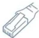
To power the device via a PoE-Switch (e.g. D-Link DGS-1008P) or PoE-Injector (e.g. DoorBird Gigabit PoE Injector A1091) in accordance with the PoE standard IEEE 802.3af Mode A, the four wires bearing the numbers 1, 2, 3 and 6 of a Cat.5 cable or better are to be used. A Cat.5 cable or better must be used as network signals can only be transmitted over completely insulated, shielded and twisted cables. If you use PoE as a source of power the four wires for PoE then simultaneously form the data link. The device won't start if your PoE-Switch/PoE-Injector
does not support the PoE Standard IEEE 802.3af Mode A (see Diagnostic-LED and Diagnostic-Sounds).

- Disconnect the PoE-Switch or PoE-Injector from the power grid.
- Run the network cable to the installation location of the device.
7
CONNECTING THE DEVICE
It is possible to connect the cables and wires to the device conveniently and safely via labelled connection ports. You can connect all necessary cables and wires to the device now. Please remove any cables and wires from the connection ports of the device that you do not need. Remove about 5 mm of insulation material at the end of the wires that you would like to connect to the green screw connection terminal of the device.

Please take care when connecting the cables and wires. Connecting the cables and wires the wrong way may damage the device.
Wires without insolation material must not protrude out of the green screw connection terminal, it may lead to electrical short and damage the device.

The yellow, green, and red cables that lead out from the side of the Main Electrical Unit must only be used to connect components certified by Bird Home Automation.

Handle the front panel with care. The surface of the front panel could be scratched or otherwise damaged if handled without care.
You can use the nylon cord to temporary fix the front panel to the mounting housing (backbox) while connecting the cables and wires to the device.

natural_image
Pure technical line drawing of a mechanical assembly without any text, numbers, or symbols
flowchart
graph TD
    A["DOORBIRD D21x"] --> B["REL1 REL2 15VDCEXT"]
    B --> C["Device 1"]
    B --> D["Device 2"]
    B --> E["Device 3"]
    B --> F["Device 4"]
    B --> G["Device 5"]
    B --> H["Device 6"]
    B --> I["Device 7"]
    B --> J["Device 8"]
    B --> K["Device 9"]
    B --> L["Device 10"]
    B --> M["Device 11"]
    B --> N["Device 12"]
    B --> O["Device 13"]
    B --> P["Device 14"]
    B --> Q["Device 15"]
    B --> R["Device 16"]
    B --> S["Device 17"]
    B --> T["Device 18"]
    B --> U["Device 19"]
    B --> V["Device 20"]
    B --> W["Device 21"]
    B --> X["Device 22"]
    B --> Y["Device 23"]
    B --> Z["Device 24"]
    B --> AA["Device 25"]
    B --> AB["Device 26"]
    B --> AC["Device 27"]
    B --> AD["Device 28"]
    B --> AE["Device 29"]
    B --> AF["Device 30"]
    B --> AG["Device 31"]
    B --> AH["Device 32"]
    B --> AI["Device 33"]
    B --> AJ["Device 34"]
    B --> AK["Device 35"]
    B --> AL["Device 36"]
    B --> AM["Device 37"]
    B --> AN["Device 38"]
    B --> AO["Device 39"]
    B --> AP["Device 40"]
    B --> AQ["Device 41"]
    B --> AR["Device 42"]
    B --> AS["Device 43"]
    B --> AT["Device 44"]
    B --> AU["Device 45"]
    B --> AV["Device 46"]
    B --> AW["Device 47"]
    B --> AX["Device 48"]
    B --> AY["Device 49"]
    B --> AZ["Device 50"]
    style DOORBIRD_D21x fill:#f9f,stroke:#333
    style DOORBIRD_D21x fill:#ccf,stroke:#333
    note right of DOORBIRD_D21x: Only related for devices with call button(s)
Each Call Button is equipped with one jack.
4 Pin: Only related for devices with call button(s)
Each Call Button is equipped with one jack.
4 Pin: Only related for devices with call button(s)
Each Call Button is equipped with one jack.
4 Pin: Only related for devices with call button(s)
Each Call Button is equipped with one jack.
4 Pin: Only related for devices with call button(s)
Each Call Button is equipped with one jack.
4 Pin: Only related for devices with call button(s)
Each Call Button is equipped
Each Call Button is equipped with one jack.
4 Pin: Only related for devices with call button(s)
Each Call Button is equipped with one jack.
4 Pin: Only related for devices with call button(s)
Each Call Button is equipped with one jack.
4 Pin: Only related for devices with call button(s)
Each Call Button is equipped with one jack.
4 Pin: Only related for devices with call button(s)
Each Call Button is equipped with one jack.
4 Pin: Only related for Devices
Each Call Button is equipped with one jack.
4 Pin: Only related for Devices
Each Call Button is equipped with one jack.
4 Pin: Only related for Devices
Each Call Button is equipped with one jack.
4 Pin: Only related for Devices
Each Call Button is equipped with one jack.
4 Pin: Only related for Devices
Each Call Button is equipped with one jack.
4 Pin: Only related for Devices
Each Call Button is equipped with one jack.
4 Pin: Only related to Device
Each Call Button is equipped with one jack.
4 Pin: Only related to Device
Each Call Button is equipped with one jack.
4 Pin: Only related to Device
Each Call Button is equipped with one jack.
4 Pin: Only related to Device
Each Call Button is equipped with one jack.
4 Pin: Only related to Device
Each Call Button is equipped with one jack.
4 Pin: Only related to Device
Each Call Button is equipped with one jack.
4 Pin: Only related to Device
Each Call Button is equipped to one jack.
4 Pin: Only related to Device
Each Call Button is equipped to one jack.
4 Pin: Only related to Device
Each Call Button is equipped to one jack.
4 Pin: Only related to Device
Each Call Button is equipped to one jack.
4 Pin: Only related to Device
Each Call Button is equipped to one jack.
4 Pin: Only related to Device
Each Call Button is equipped to one jack.
4 Pin: Only related (up) or (down) connection
PORT DESCRIPTION
| LAN/POE RJ45 jack to connect a standard Network cable Cat.5 or better, coming from the Internet Router/PoE-Switch/PoE-Injector.NOTICEDo not power the device simultaneously via the power supply from the power supply unit (mains adaptor) and the power supply via PoE. | |
| REL1, REL1 | Bi-stable latching relay #1, max. 24 V DC/AC, 1 Ampere. Security feature: The relay keeps its state even in the case of loss of power. You can configure the default state of the relay (open/close) via the DoorBird App. These ports can be used to connect e.g. an electric door opener. The device does not supply power to the connected device. The power supply for the electric door opener must be installed separately.When wiring an electric door opener directly to a door station, there is a risk that the electric door opener could be tampered by unauthorized third parties (e. g. by breaking the door station and short-circuiting the wiring of the door opener). Therefore, we generally recommend the use of a remote safety relay mounted indoors (e. g. DoorBird I/O Door Controller A1081) for wiring an electric door opener for a more secure installation in your home. |
| REL2, REL2 | Bi-stable latching relay #2, max. 24 V DC/AC, 1 Ampere. Security feature: The relay keeps its state even in the case of loss of power. You can configure the default state of the relay (open/close) via the DoorBird App. These ports can be used to connect e.g. an electric door opener. The device does not supply power to the connected device. The power supply for the electric door opener must be installed separately.When wiring an electric door opener directly to a Door station, there is a risk that the electric door opener could be tampered by unauthorized third parties (e. g. by breaking the door station and short-circuiting the wiring of the door opener). Therefore, we generally recommend the use of a remote safety relay mounted indoors (e. g. DoorBird I/O Door Controller A1081) for wiring an electric door opener for a more secure installation in your home. |
| BELL, BELL | NOTICEReserved - Do not use! |
| EXT, EXT | Door opener button, max. 0 V DC/AC, 0 Ampere. These ports can be used to connect e.g. a door opener button inside the home. It will trigger the first bi-stable latching relay of the device (REL1, REL1).NOTICEPlease make sure to add no voltage on these ports. Extra voltage may destroy the device immediately. |
| 15 VDC - | 15 V DC Power supply input, negative pole (-). Please connect the black wire of the DoorBird power supply unit (mains adaptor) here, if you do not power the device using PoE.NOTICEDo not power the device simultaneously via the power supply from the power supply unit (mains adaptor) and the power supply via PoE. |
| 15 VDC + 15 V DC Power supply input, positive pole (+). Please connect the red wire of the DoorBird power supply unit (mains adaptor) here, if you do not power the device using PoE.NOTICEDo not power the device simultaneously via the power supply from the power supply unit (mains adaptor) and the power supply via PoE. | |
| Only related for devices with call button(s): | |
| 4 PIN (SWITCH) | Use the yellow cable to connect the button to the IP Video Door Station. |

Please take care when connecting the cables and wires. Connecting the cables and wires the wrong way may damage the device. Wires without insolation material must not protrude out of the green screw connection terminal, it may lead to electrical short and damage the device.
8
ASSEMBLING THE FRONT PANEL
Assemble the front panel of the device to the mounting housing (backbox) of the device.
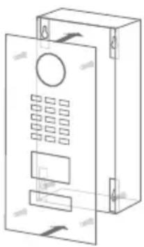
natural_image
Technical line drawing of a rectangular electronic device with internal components and mounting holes (no text or symbols)
natural_image
Technical line drawing of a server rack with a close-up inset showing the door handle (no text or symbols)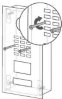
natural_image
Technical line drawing of a cabinet with internal components and a magnified inset showing a mechanical component (no text or symbols)1.) Pull the front panel into the mounting housing (backbox)
2.) Push the front panel up.
3.) Insert the security screws.
9
ACTIVATING THE DEVICE
Switch on the power leading to the assembly location again. If you use PoE, make sure to switch on power of the PoE-Switch or PoE-Injector you have connected the device to.

Do not power the device simultaneously via the power supply from the power supply unit (mains adaptor) and the power supply via PoE.
You can see if the device is powered by checking the Diagnostic-LED, which lights up after about 30 to 60 seconds after the power is connected. The device is ready for operation (booting up process, any software updates, etc.) once it has emitted a short diagnosis sound from the integrated loudspeaker. This may last for up to 5 minutes. If the Diagnostic LED does not light up, please check the power supply. Please also check whether you have used a wall-plug power supply and not PoE and whether you have connected the positive pole and negative pole to the device correctly.
10
DOWNLOADING AND INSTALLING THE APP
Download the "DoorBird" App by Bird Home Automation onto your mobile device from the Apple App Store or Google Play Store. You can always find the most up-to-date version of the App manual on www.doorbird.com/support
Go to DoorBird App "Settings > Add device" and click on the QR code icon in the "User" field. Scan the user QR code found on the "Digital Passport" provided with the device.
If you have problems adding the device to the App, please check if the device is online (www.doorbird.com/checkonline). If the device is not online, please check the network connection and the power supply of the device.
DIAGNOSTIC-LED
You can see if the device is powered by checking the Diagnostic-LED, which lights up after about 30 to 60 seconds after the power is connected.
DIAGNOSTIC-SOUNDS
After around one to five minutes, the device emits brief diagnostic sounds after it has been connected to the power grid.
MOTION SENSOR
The device has a built-in Motion Sensor with 4D Technology. You can use it for numerous applications, e.g. to send an alarm to a mobile device or to switch a relay to turn on an outdoor light.
RFID READER
The built-in RFID reader can be used for many applications, e.g. to open/lock doors or arming/disarming your alarm system. For security reasons, the RFID reader has a very short range (0 - 3 cm, 0 - 1.18 in), so you must place the compatible RFID tag (key fob) very close to the RFID reader. You can configure the RFID reader using the DoorBird App.

The RFID reader works only on short distance, for security reasons.
API
The device features a well documented API for third-party integration. For information, terms and conditions see www.doorbird.com/api
DOORBIRD CONNECT
The device features many options to integrate it into third-party applications. For information, terms and conditions see www.doorbird.com/connect
CHANGING THE LABEL OF A CALL BUTTON NAMEPLATE
Applies only to devices with 1 and more illuminated call buttons with nameplate.
Engraving Service

Engraving service for a modern and clean appearance: www.doorbird.com/engraving

Please follow STEP 1 to switch off power. We recommend to use a thin slot screwdriver to remove the cover of the nameplate. We recommend to use white paper for the label which does not absorb moisture.

natural_image
Line drawing of a hand holding a rectangular object with a small circular symbol, no text or labels present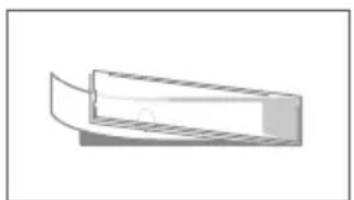
natural_image
Simple 3D diagram of a rectangular object with a curved top edge and a small protrusion, no text or symbols present.
CHANGING THE LABEL OF THE INFO MODULE

Applies only to devices with Info Module.
Please follow STEP 1 to switch off power and STEP 2 to open the device. You can then change the labeling of the Info Module in the inside. We recommend to use white paper for the label which does not absorb moisture.
CONNECTING CALL BUTTONS TO THE MULTI TENANT MODULE

Applies only to devices with 2 and more illuminated call buttons with nameplate.
Connect only call buttons to the Multi Tenant Module (e.g. Multi Tenant Module MTM18A) certified by Bird Home Automation.

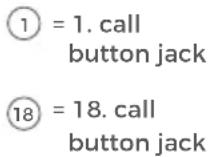
MAINTENANCE FOR DOORBIRD PRODUCTS
Cleaning and maintenance instructions
All DoorBird door stations are made of high-quality materials and are designed for a durable lifetime. Since door stations are usually installed in unprotected outdoor areas, they are exposed to adverse weather conditions and aggressive substances, especially close to frequently used roads, in coastal and industrial areas. Therefore please consider the following care instructions. Unfortunately, we cannot accept any liability for damage if these instructions are not being observed.
Aggressive dirt such as bird droppings should be removed as quickly as possible.

Never use abrasive detergents such as steel wool or scouring milk!
Warm water is usually sufficient, if necessary with a little detergent, a soft cloth or brush. Plastic parts (camera or name tags) must not be treated with metal care products. Remove all residues of cleaning agents or lubricants to avoid stains or discolouration after the maintenance.
Stainless Steel
Only high-quality German stainless steel is used for all available DoorBird door stations. However, high-quality stainless steel can also rust, as approx. 70% of stainless steel is made of iron. Rust resistance is only achieved by a protective layer (also called passive layer), which covers the iron like a skin. This protective layer consists essentially of chromium and other precious metals.
Iron particles, grinding dust and chips deposited on stainless steel can lead to corrosion (rust film). These
iron particles can be found everywhere, but especially in coastal and industrial areas and close to frequently used roads. Please remove ferrous deposits immediately, as they will attack your door station and lead to real rust if not removed. To remove rust, simply wipe off the dust; in addition, a care product is recommended, e.g. WD 40, available e.g. at Amazon for less than € 5.00. Simply apply in a thin layer and rub in. The same applies if rust appears on the engravings on the stainless steel surface.
Cement or lime splashes should be carefully removed as soon as possible with a wooden spatula before hardening.
The following cleaning detergents are not to be used as they reduce corrosion resistance:
- products containing chloride and hydrochloric acid
- Bleach (in case of accidental use, rinse thoroughly with water)
- Silver polish
After the cleaning with clear water wipe with damp cloth and rub dry to avoid lime traces. Lime residues can be avoided by using demineralised water.
Stainless steel PVD coated
PVD coated, chrome-plated or gold-plated surfaces are recommended to be cleaned with a grease-dissolving detergent and clear water or with a clean and dust-free microfibre cloth. For high-gloss surfaces, use a scratch-free cloth (e.g. cleaning cloth for glasses, furniture polishing cloth, etc.).
Lacquered surfaces
Clean painted surfaces and lettering with a soft, scratch-free cloth moistened with a mild soap solution (e.g. cleaning cloth for glasses, furniture polishing cloth, etc.). To prevent stains or discolouration, the detergents should be wiped off without leaving any residue. Be particularly careful with lettering in order not to damage the film or the print.
TECHNICAL SPECIFICATIONS
| GENERAL | |
| Power supply | 15 V DC (max. 15 W) or Power over Ethernet (PoE 802.3af Mode-A) |
| Info Module* | 3.5", illuminated |
| Display Module* | 3.5" LCD (no touch function), illuminated, for the display of a 2-line free text and the name directory (max. 100 entries) |
| Keypad Module* | 16 keys, illuminated, configurable via App. e.g.Individual PIN codesIndividual events (e.g. switch a relay, push notification, SIP call [audio/video], HTTP(s) request)Individual schedulesUp to 100 PIN codes manageable |
| Connectors | RJ45, for LAN/PoEBi-stable latching relay #1, max. 24 V DC/AC, 1 Ampere, e.g. for electric door openerBi-stable latching relay #2, max. 24 V DC/AC, 1 A, e.g. for electric door openerExternal input for external door opener button (potential-free)15 V DC input (+,-), max. 15 WRelays can be expanded / detached with DoorBird I/O Door Controller |
| Weather-proof | Yes, IP65 |
| Approvals | IP65, CE, FCC, IC, RoHS, IK08, REACH, IEC/EN 62368, IEC/EN 62471 |
| Operating conditions | -25 to +55°C / -13 to 131°FHumidity 10 to 85 % RH (non-condensing) |
| Scope of delivery | 1x Main Electrical Unit1x Front panel*(110 - 240 V AC to 15 V DC)1x RFID key fob1x Screwdriver1x Quickstart guide with Digital Passport1x Installation manual1x Small parts |
| Warranty | see www.doorbird.com/warranty |
CURRENT SYSTEM REQUIREMENTS
| System requirements | Mobile device: Newest iOS on iPhone/iPad, newest Android on Smartphone/TabletInternet: High-Speed Landline Broadband Internet connection, DSL, cable or fiber optic, no socks or proxy serverNetwork: Ethernet Network, with DHCP |
| Recommended installation height | Camera lens should be at a min. height of 145 cm (57 in). Before the installation please determine your optimal installation height. |
VIDEO
| Camera | HDTV 720p, dynamic (VGA - HDTV) |
| Lens | High-end ultra wide-angle hemispheric lens 180^ (D), 140^ (H), 100^ (V), straightened, IR-capable |
| Night-vision | Yes, light sensor, automatic IR-cut filter, 12 Infrared LEDs (850 nm) |
AUDIO
| Audio components | Speaker and microphone, noise reduction and echo cancellation (ANR, AEC) |
| Audio streaming | Two-way, full duplex |
NETWORK
| Ethernet | RJ45 jack, PoE 802.3af Mode-A, 10/100 Base-T |
| Supported protocols | HTTP, HTTPS, SSL/TLS, Bonjour, DNS, RTSP, RTP, TCP, UDP, RTCP, ICMP, DHCP, ARP, SIP, DTMF (RTP [RFC-2833], SIP INFO [RFC-2976]), STM |
MOTION SENSOR
| Type | Active |
| Detection angle | 54° (H), 70° (V) |
| Range | 1 - 10 m (3.3 - 32.9 ft), depends on environment, configurable in 1 m (3.3 ft) steps.If a “Display Module” is connected to the Main Electrical Unit, the range is limited to 1 m (3.3 ft). |
| Technology | 4D. Based on multiple integrated sensors and algorithms, e.g. Radio Frequency Energy (RFE) |
| Configuration | Via App, e.g.Range (1 - 10 m / 3.3 - 32.9 ft)Movement direction (coming, leaving, both)Individual events (e.g. switch a relay, push notification, SIP call [audio/video], HTTP(s) notification)Individual schedules |
RFID
| Type | Active Reader Passive Tag (ARPT) system |
| Standard | ISO/IEC 18000-2:2009 Part 2, EM4100, EM4102 |
| Frequency | 125 KHz |
| Range | 0 - 3 cm, depends on environment |
| Antenna | Internal |
| Compatible Transponder | RFID key fobs, sold separately, see www.doorbird.com/buyUp to 100 tags manageable |
| Configuration | Via App, e.g. Tag (add, delete)Individual events (e.g. switch a relay, SIP call [audio/video], HTTP(s) notification)Individual schedules |
INTEGRATED WIRELESS MODULES
| RFID | 125 KHz |
| Sensor | 24 GHz, can be disabled |
THIRD-PARTY INTEGRATION (DOORBIRD CONNECT)
| Partnerintegrations see www.doorbird.com/connect | |
| API see www.doorbird.com/api | |
| Simultaneous video streams | One, for event-based and continuous recording |
OPTIONAL ACCESSORIES
| Sold separately | see www.doorbird.com/buy |
Errors and omissions excepted.
LEGAL NOTES
General remarks
- DoorBird is a registered trademark of Bird Home Automation GmbH.
- Apple, the Apple logo, Mac, Mac OS, Macintosh, iPad, Multi-Touch, iOS, iPhone and iPod touch are trademarks of Apple Inc.
- Google, Android and Google Play are trademarks of Google, Inc.
- The Bluetooth® word mark and logos are registered trademarks of Bluetooth SIC, Inc.
- All other company and product names may be trademarks of the respective companies with which they are associated.
- We reserve the right to make changes to our products in the interests of technical advancement. The products shown may also look different from the products supplied based on ongoing enhancement.
- Reproducing or using texts, illustrations and photos from this instruction manual in any media - even if only in the form of excerpts - shall only be permitted with our express written consent.
- The design of this manual is subject to copyright protection. We do not accept any liability for any errors or any erroneous content or printing errors (even in the case of technical specifications or within graphics and technical sketches).
- Our products are in compliance with all technical guidelines, electrical and telecommunications regulations applicable in Germany, the EU and the USA.
- Our products and also the components contained therein (ICs, software, etc.) may only be used for civilian non-military purposes.
Data privacy and data security
- For maximum security, the device uses the same encryption technologies as are used in online banking. For your security, no port forwarding or DynDNS is used either.
- The data centre location for remote access over the Internet by means of an App is obligatory in the EU if the determined Internet IP-Address location of the device is within the EU. The data centre is operated in line with the most stringent security standards.
- Video, audio and any other surveillance methods can be regulated by laws that vary from country to country. Check the laws in your local region before installing and using this device for surveillance purposes.
If the device is a door-, indoor station or camera:
- In many countries video and voice signal may only be transmitted once a visitor has rung the bell (data privacy, configurable in the App).
- Please carry out the mounting in such a way that the detection range of the camera limits the device exclusively to the immediate entrance area.
- The device may come with a visitor history and motion sensor. You can activate/deactivate this function if required.
If necessary, indicate the presence of the device in a suitable place and in a suitable form.
Please observe any relevant country-specific statutory regulations concerning the use of surveillance components and surveillance cameras applicable at the installation site.
Check with the property owner and your house community if you are allowed to install and use this product. Bird Home Automation GmbH cannot be held responsible for any miss-use or miss-configuration of this product, including the unauthorized opening of a door.
Bird Home Automation cannot be held responsible for damages caused by improper existing installations or improper installation.
Software and operating system's updates (so-called "firmware updates") are generally automatically installed on the products of Bird Home Automation GmbH via Internet, if technically possible. Automatic firmware updates keep the products' software up to date so that they always work reliably, safely and efficiently. Through further development, features can be added, extended or slightly changed. Major changes or limitations to existing features will generally occur if Bird Home Automation GmbH deems it necessary (e.g. for data protection, data security or stability reasons, or to keep them up to date). When a firmware update is available, Bird Home Automation GmbH's servers generally automatically distribute it to all compatible products connected to the Internet or Bird Home Automation GmbH's servers. This process is gradual and can take several weeks. As soon as a product receives a firmware update, the system will be installed and will restart by itself. Installed firmware updates cannot be undone. Since the products and software of Bird Home Automation GmbH are not explicitly customer-specific products, a customer cannot deny an automatic update if the product is connected to the Internet or to the Bird Home Automation GmbH's server.
Publisher
It is possible that these manual still contains typographical errors or printing errors. The information in this manual will be checked regularly and corrections will be made in the next version. We accept no liability for errors of a technical or printing nature and their consequences.
natural_image
Simple line drawing of a rectangular frame with a central circular element and an arrow pointing to it, labeled with number 9 (no text or symbols on the diagram itself)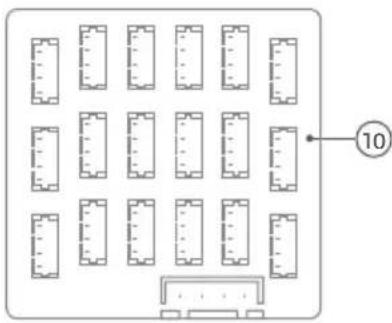
natural_image
Simple line drawing of a container with two circular components and three empty circles, no text or symbols present.natural_image
Simple line drawing of a screwdriver inserted into a circular component (no text or symbols)natural_image
Pure diagram of a coiled cable or wire inside a circular housing, with no text, numbers, or symbols present.natural_image
Technical line drawing of a mechanical assembly with a circular component and diagonal rod (no text or symbols)
natural_image
Technical line drawing of a rectangular electronic device with internal components and mounting holes (no text or symbols)natural_image
Diagram of a server rack with a lock and door, showing internal compartments and a close-up view (no text or symbols)natural_image
Technical line drawing of a mechanical device with an inset showing a close-up of a tool interacting with a grid-patterned component (no text or symbols present)natural_image
Line drawing of a hand holding a tool with a small bell icon, no text or symbols present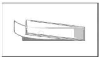
natural_image
Simple 3D diagram of a mechanical component with no visible text or symbols
MANUEL D'INSTALLATION

natural_image
Simple line drawing of a rectangular frame with a central circular dot and number 9 on the side (no text or symbols)
natural_image
Simple line drawing of a rectangular container with two circular components and a connecting rod (no text or symbols)natural_image
Simple line drawing of a screwdriver with a circular head and connecting rod (no text or symbols)natural_image
Pure technical line drawing of a mechanical assembly without any text, numbers, or symbols
natural_image
Three technical diagrams showing a door panel installation with a close-up of the door handle and a magnified view of the lock mechanism (no text or symbols present)natural_image
Line drawing of a hand holding a rectangular object with a small bell icon, no text or symbols present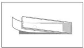
natural_image
Simple 3D illustration of a rectangular block with a curved cutout, no text or symbols present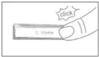
CONNECTER LES BOUTONS D'APPEL AU MODULE MULTI-RÉSIDENTIEL

EJEMPLO DE DISPOSITIVO CON MÓDULO DE DISPLAY Y MÓDULO DE TECLADO
Frontal

natural_image
Isometric line drawing of a rectangular device with internal compartments and a circular top (no text or symbols)natural_image
Line drawing of a rectangular electronic device with internal components and mounting holes (no text or symbols)natural_image
Simple line drawing of a container with two circular components and connecting rods (no text or symbols)natural_image
Simple line drawing of a screwdriver with a circular head and handle (no text or symbols)natural_image
Pure diagram of a circular object with internal curved lines and a small circle, no text or symbols present.natural_image
Technical line drawing of a mechanical assembly with a magnified inset showing a cylindrical component (no text or symbols)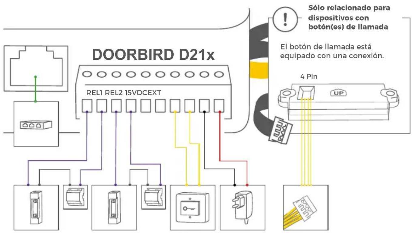
natural_image
Three technical line drawings of a door panel with internal components and a close-up inset showing the lock mechanism (no text or symbols)- INSTALLATION MANUAL
- Liability
- Equipment Modifications
- Symbols used
- Hazard information
- WARNING
- Safety instructions
- NOTICE
- Information on disposal for users of waste electrical & electronic equipment (private household)
- Information on disposal in other countries outside the European Union
- Transportation
- Warranty Information
- Front
- INSIDE
- DEVICE EXAMPLE WITH 2 AND MORE CALL BUTTONS
- DEVICE EXAMPLE WITH DISPLAY MODULE AND KEYPAD MODULE
- DEVICE EXAMPLE WITH INFO MODULE AND KEYPAD MODULE
- VIDEOS
- INSTALLATION
- Network speed and network components
- Requirements:
- 1
- SWITCHING OFF POWER
- 2
- DISMANTLING THE EXISTING DOORBELL
- 3
- DETERMINING THE ASSEMBLY LOCATION
- !
- 4
- REMOVING THE FRONT PANEL
- 5
- ASSEMBLING THE MOUNTING HOUSING
- Mounting the surface-mounted housing
- 6
- POWER SUPPLY OPTIONS
- OPTION 1
- OPTION 2
- 7
- CONNECTING THE DEVICE
- 8
- ASSEMBLING THE FRONT PANEL
- 9
- ACTIVATING THE DEVICE
- 10
- DOWNLOADING AND INSTALLING THE APP
- DIAGNOSTIC-LED
- DIAGNOSTIC-SOUNDS
- MOTION SENSOR
- RFID READER
- API
- DOORBIRD CONNECT
- CHANGING THE LABEL OF A CALL BUTTON NAMEPLATE
- Engraving Service
- CHANGING THE LABEL OF THE INFO MODULE
- CONNECTING CALL BUTTONS TO THE MULTI TENANT MODULE
- MAINTENANCE FOR DOORBIRD PRODUCTS
- Cleaning and maintenance instructions
- Stainless Steel
- Stainless steel PVD coated
- Lacquered surfaces
- LEGAL NOTES
- General remarks
- Data privacy and data security
- Publisher
- MANUEL D'INSTALLATION
- CONNECTER LES BOUTONS D'APPEL AU MODULE MULTI-RÉSIDENTIEL
- EJEMPLO DE DISPOSITIVO CON MÓDULO DE DISPLAY Y MÓDULO DE TECLADO
- EU DECLARATION OF CONFORMITY (DoC)
Brand : DoorBird
Model : D2102V
Category : Intercom