
Bravia KD49XG8196 - Television SONY - Free user manual and instructions
Find the device manual for free Bravia KD49XG8196 SONY in PDF.


| Product type | LED 4K UHD TV |
| Brand | Sony |
| Model | Bravia KD49XG8196 |
| Screen size | 49 inches (123 cm) |
| Resolution | 3840 x 2160 pixels (4K UHD) |
| Display technology | LED (Direct LED) |
| HDR compatibility | HDR10, HLG, Dolby Vision |
| Operating system | Android TV |
| Processor | 4K HDR Processor X1 |
| Connectivity | 4 HDMI inputs, 3 USB ports, 1 Ethernet port, built-in Wi-Fi, Bluetooth |
| Dimensions (without stand) | 1101 x 645 x 80 mm (width x height x depth) |
| Dimensions (with stand) | 1101 x 695 x 255 mm (width x height x depth) |
| Weight (without stand) | Approx. 13 kg |
| Weight (with stand) | Approx. 14 kg |
| Power consumption | 120 W (estimated) |
| Power supply voltage | 220-240 V AC, 50/60 Hz |
| Energy class | A |
| Main features | Smart TV, 4K HDR, Android TV, built-in Chromecast, compatible with Alexa |
| Care and cleaning | Clean the screen with a soft, dry cloth; do not use chemicals. |
| Safety | Professional wall mounting recommended; do not expose to water or humidity; do not block ventilation openings. |
| Spare parts and repairability | Remote control, table stand, screws, batteries; contact Sony after-sales service for spare parts. |
| General information | 2-year warranty; manufactured in Malaysia (estimated). |
Frequently Asked Questions - Bravia KD49XG8196 SONY
User questions about Bravia KD49XG8196 SONY
0 question about this device. Answer the ones you know or ask your own.
Ask a new question about this device
Download the instructions for your Television in PDF format for free! Find your manual Bravia KD49XG8196 - SONY and take your electronic device back in hand. On this page are published all the documents necessary for the use of your device. Bravia KD49XG8196 by SONY.
USER MANUAL Bravia KD49XG8196 SONY
* In the actual model names, the "☐☐" indicates numbers and/or characters specific to each model.
To Customers
For product protection and safety reasons, Sony strongly recommends that installation of your TV be performed by Sony dealers or licensed contractors. Do not attempt to install it yourself.
To Sony Dealers and Contractors
Provide full attention to safety during the installation, periodic maintenance and examination of this product.
Sufficient expertise is required for installing this product, especially to determine the strength of the wall for withstanding the TV's weight. Be sure to entrust the attachment of this product to the wall to Sony dealers or licensed contractors and pay adequate attention to safety during the installation. Sony is not liable for any damage or injury caused by mishandling or improper installation.
For safety and proper installation, follow the Wall-mount Bracket Operation Instructions, TV Setup Guide, and the directions in this manual.
On Safety
Thank you for purchasing this product.
To Customers
Sufficient expertise is required for installing this product. Be sure to subcontract the installation to Sony dealers or licensed contractors and pay special attention to safety during the installation. Sony is not liable for any damages or injury caused by mishandling or improper installation, or installing any other than the specified product. Your Statutory Rights (if any) are not affected.
To Sony dealers
Sufficient expertise is required for installing this product. Be sure to read this instruction manual thoroughly to do the installation work safely. Sony is not liable for any damages or injury caused by mishandling or improper installation. Please give this manual to the customer after installation.
This instruction manual shows the correct handling of the product and important precautions necessary to prevent accidents. Be sure to read this manual thoroughly and use the product correctly. Keep this manual available for future reference.
Products by Sony are designed with safety in mind. If the products are used incorrectly, however, it may result in a serious injury through fire, electric shock, the product toppling over, or the product dropping. Be sure to observe the precautions for safety to prevent such accidents.
CAUTION
Specified products
This Wall-Mount Bracket is designed for use with the products specified TVs. For TVs, refer to their Reference Guide to verify that the Wall-Mount Bracket can be used.
To Customers
WARNING
If the following precautions are not observed, serious injury or death through fire, electric shock, or the product dropping can result.
Be sure to subcontract the installation to licensed contractors and keep small children away during the installation.
If the Wall-Mount Bracket or the TV is not installed correctly, the following accidents may occur. Be sure licensed contractors carry out installation.
- The TV may fall and cause a serious injury such as a bruise or a fracture.
- If the wall on which the Wall-Mount Bracket is installed is unstable, uneven, or not perpendicular to the floor, the unit may fall and cause injury or property damage. The wall should be capable of supporting a weight of at least four times the TV weight. (Refer to your TV's Reference Guide for its weight.)
- If the installation of the Wall-Mount Bracket on the wall is not sufficiently sturdy, the unit may fall and cause injury or property damage.
Be sure to subcontract moving or dismounting of the TV to licensed contractors.
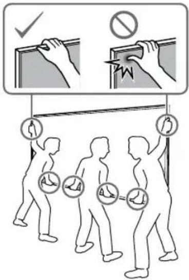
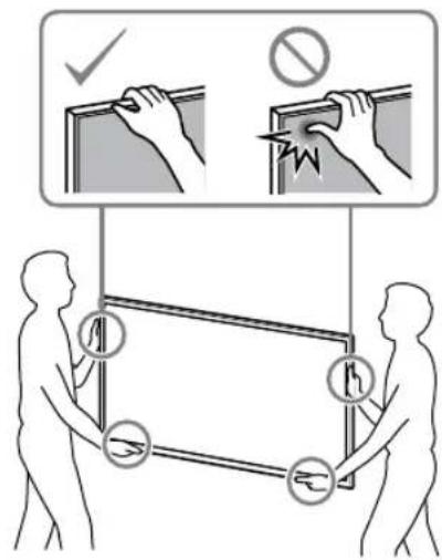
If persons other than licensed contractors transport or dismount the TV, it may fall and cause injury or property damage. Be sure that two or more persons (three or more persons for 75 inches and above TV set) carry or dismount the TV.
Do not remove screws, etc., after mounting the TV.
If you do so, the TV may fall and cause injury or property damage.
Do not make alterations to the parts of the Wall-Mount Bracket.
If you do so, the Wall-Mount Bracket may fall and cause injury or property damage.
Do not mount any equipment other than the specified product.
This Wall-Mount Bracket is designed for use with the specified product only. If you mount equipment other than specified, it may fall or break, and cause injury or property damage.
Do not apply any load other than the TV on the Wall-Mount Bracket. Do not shake the TV left/right, up/down.
If you do so, the TV may fall and cause injury or property damage.
Do not lean on or hang from the TV.
Do not lean on or hang from the TV as it may fall on you and cause serious injury.
CAUTION
If the following precautions are not observed, injury or property damage may occur.
Do not handle the product with excessive force during cleaning or maintenance.
Do not apply excessive force on the topside of the TV. If you do so, the TV may fall and cause injury or property damage.
Precautions
- If you use the TV installed on the Wall-Mount Bracket for a long time, the wall behind or above the TV may become discolored or the wallpaper may come unstuck, depending on the material of the wall.
- If the Wall-Mount Bracket is removed after installing it on the wall, the screw holes are left.
- Do not use the Wall-Mount Bracket in a place where it is subjected to mechanical vibrations.
Installing the Wall-Mount Bracket
To Sony Dealers
WARNING
The following instructions are for Sony dealers only. Be sure to read the safety precautions described above and pay special attention to safety during the installation, maintenance, and checking of this product.
Do not install the Wall-Mount Bracket on wall surfaces where the corners or sides of the TV protrude away from the wall surface.
Do not install the Wall-Mount Bracket on wall surfaces such as a pillar, where the corners or sides of the TV protrude away from the wall surface. If a person or object happens to hit the protruded corner or side of the TV, it may cause injury or property damage.
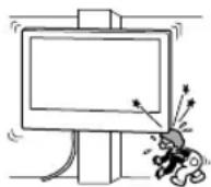
Do not install the TV over or under an air conditioner.
If the TV is exposed to water leaks or air current from an air conditioner for a long time, it may cause a fire, an electric shock, or a malfunction of the TV.
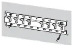
Be sure to install the Wall-Mount Bracket securely to the wall following the instructions in this instruction manual.
If any of the screws are loose or fall out, the Wall-Mount Bracket may fall and cause injury or property damage. Be sure to use the appropriate screws for the material of the wall and install the unit securely using four or more screws of 8 mm diameter (or equivalent).
Be sure to use the supplied screws and attachment parts properly following the instructions given in this instruction manual. If you use substitute items, the TV may fall and cause bodily injury to someone or damage to the TV.
Be sure to assemble the bracket properly following the instructed procedure explained in this instruction manual.
If any of the screws are loose or fall out, the TV may fall and cause bodily injury to someone or damage to the TV.
Be sure to tighten the screws securely in the designated position.
If you fail to do so, the TV may fall and cause bodily injury to someone or damage to the TV.
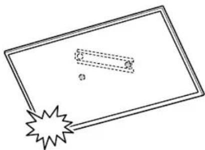
Be careful not to subject the TV to shock during installation.
If the TV is exposed to shock, it may fall or break apart. This may cause injury.
Be sure to install the TV on a wall that is both perpendicular and flat.
If you fail to do so, the TV may fall and cause injury.
After proper installation of the TV, secure the cables properly.
If people or objects get tangled with cables, this may result in injury or damage to the TV.
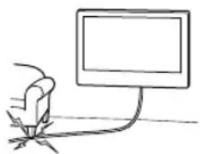
Do not allow the mains lead or the connecting cable to be pinched.
If the mains lead or the connecting cable is pinched between the unit and the wall or is bent or twisted by force, the internal conductors may become exposed and cause a short circuit or an electrical break. This may cause a fire or an electric shock.
The screws needed to secure the Wall-Mount Bracket to the wall are not supplied.
Use the appropriate screws for the wall material and structure when mounting the Wall-Mount Bracket.
Table of Contents
Preparing for installation....5
Checking the parts....5
Deciding on the installation location 6
Installing the Base on the wall 8
Preparing for the installation of the TV......9
KD-75XG80□□ 9
KD-65XG81□□ / 65XG80□□.... 10
KD-55XG81□□ / 55XG80□□....11
KD-49XG81□□ / 49XG80□□ / 43XG81□□ / 43XG80□□....12
Installing the TV on the wall....14
KD-75XG80□□ 14
KD-65XG81□□ / 65XG80□□ / 55XG81□□ / 55XG80□□ / 49XG81□□ / 49XG80□□ / 43XG81□□ / 43XG80□□....16
Confirming the completion of the
installation....19
Other information....19
Specifications....19
Installing the TV onto the wall
Installation procedure differs, depending on your TV.
Use the Wall-Mount Bracket SU-WL450 to install the TV to the wall.
Note
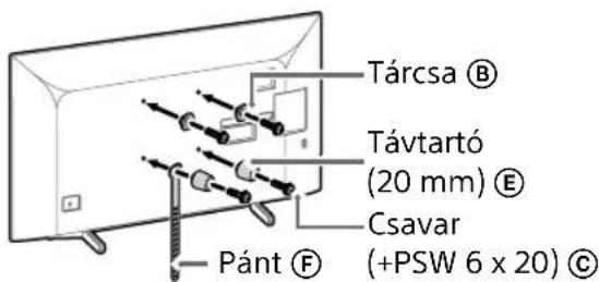
- If the Table-Top Stand is attached to the TV, detach the Table-Top Stand beforehand. See the Setup Guide and follow in reverse order the steps to detach the Table-Top Stand.
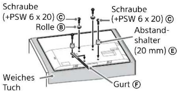
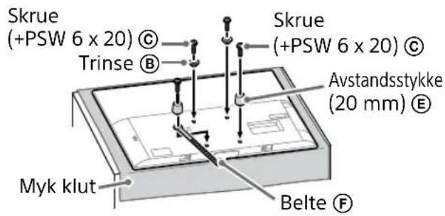
- Place the TV with its screen facing down on a level and stable surface covered with a thick and soft cloth, when securing the Attachment parts for Wall-Mount Bracket or when removing the Table-Top Stand from the TV to prevent damaging the surface of the LCD display.
- Be sure to store the removed screws in a safe place, keeping them away from children.
Preparing for installation
- Have the TV's Reference Guide and Setup Guide at hand before installation.
- Be sure to have a Phillips screwdriver that fits the screws prior to the assembly.
- Confirm the installing position of your TV.
- Prepare four or more screws of 8 mm diameter and one screw of 5 mm or equivalent (not supplied). Select screws suitable for the material of the wall.
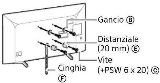
Checking the parts
Supplied with SU-WL450
- Verify that all the parts are included.
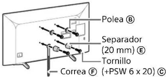
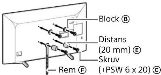
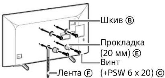
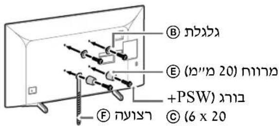
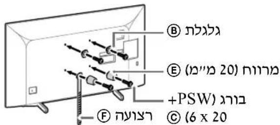
A Base (20) (1) B Pulley (2)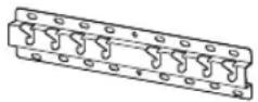 |  |
C PSW 6x20 (4) D PSW 4x20 with Bush (2) |  |
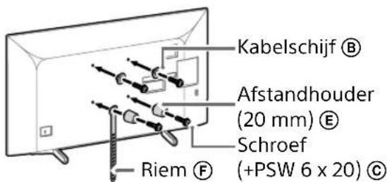
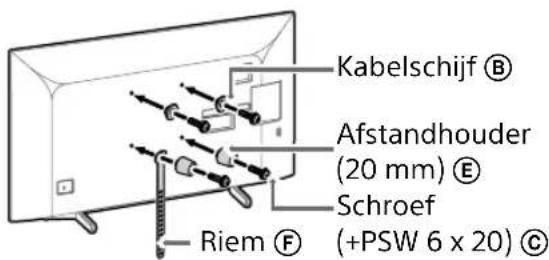
E Spacer (20) (2) F Belt (1) | 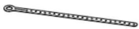 |
G Bush (20) (M4) (2) H PSW 4x20 (2) |  |
I Base Adaptor (2) J PSW 4x10 (8) |  |
K Spacer (60) (2) L PSW 6x50 (2)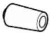 | 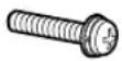 |
M Bush (M4) (2) N PSW 4x50 (2)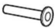 | 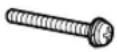 |
Deciding on the installation location
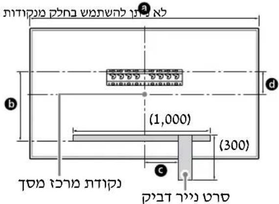
1 Decide on the installation location.
Make sure that the wall has enough space for the TV and is capable of supporting a weight of at least four times that of the TV.
Refer to the following table on installing the TV to the wall. Refer to your TV's Reference Guide for the TV's weight.
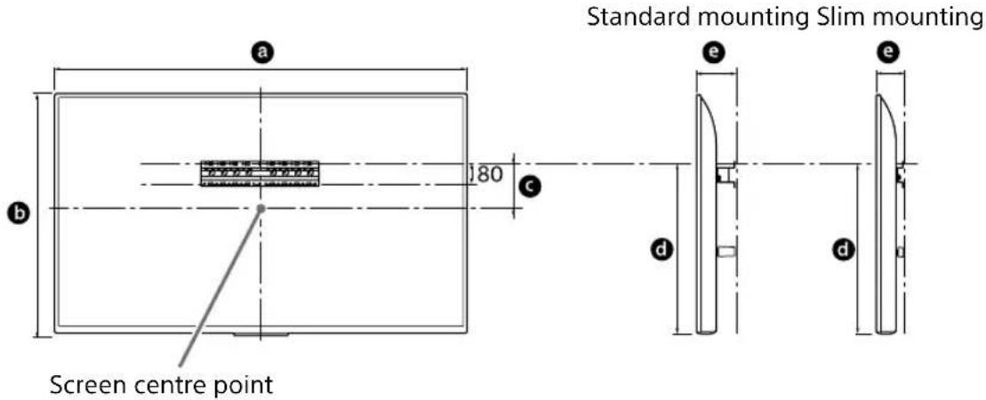
Unit: mm
| Model Name | Display dimensions | Screen centre dimension | Length for mounting | ||
| a | b | c | d | e | |
| Standard mounting Slim mounting | |||||
| KD-75XG80□□ | 1,686 | 970 202 | 690 142 100 | ||
| KD-65XG81□□ | 1,463 | 845 | 173 597 142 100 | ||
| KD-65XG80□□ | 1,463 | 845 | 173 597 142 100 | ||
| KD-55XG81□□ | 1,241 | 721 | 95 460 141 100 | ||
| KD-55XG80□□ | 1,241 | 721 | 95 460 141 100 | ||
| KD-49XG81□□ | 1,101 | 645 | -15* 314 | 119 | 78 |
| KD-49XG80□□ | 1,101 | 645 | -15* 314 | 119 | 78 |
| KD-43XG81□□ | 970 | 570 | 23 315 119 | 77 | |
| KD-43XG80□□ | 970 | 570 | 23 315 119 | 77 | |
* Bracket positioning is below the screen centre point.
Note
- Figures in the table may differ slightly depending on the installation.
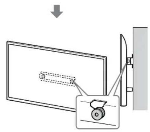
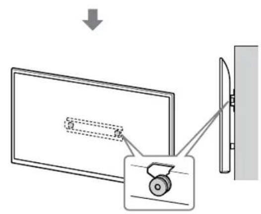
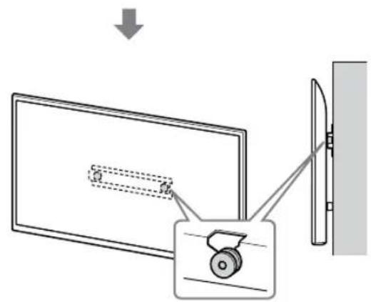
- When your TV is installed on the wall, the upper side of the TV slightly leans forward.
Allow for suitable clearance between the TV and the ceiling and protruding parts of the wall as shown below.
Unit: mm
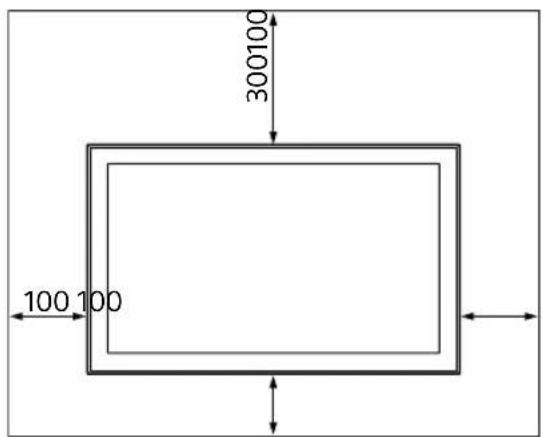
• To ensure proper ventilation and prevent the collection of dirt or dust:
— Do not lay the TV set flat, install upside down, backwards, or sideways. — Do not place the TV set on a shelf, rug, bed or in a closet. — Do not cover the TV set with a cloth, such as curtains, or items such as newspapers, etc. — Do not install the TV set as shown below.
Air circulation is blocked.
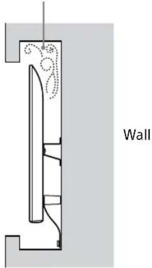
Note
- If you intend to route the cables in the wall, make a hole in the wall to insert the cables before beginning the installation.
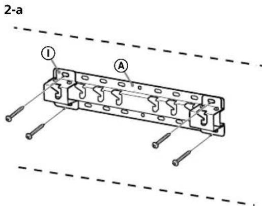
To prevent pinching the cables, prepare a hole in the wall somewhere outside the perimeter of the Base (20) Ⓐ, Base Adaptor ① and Spacer (20) Ⓔ, Spacer (60) Ⓗ.
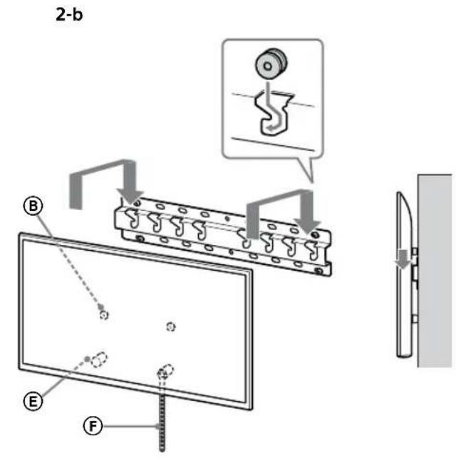
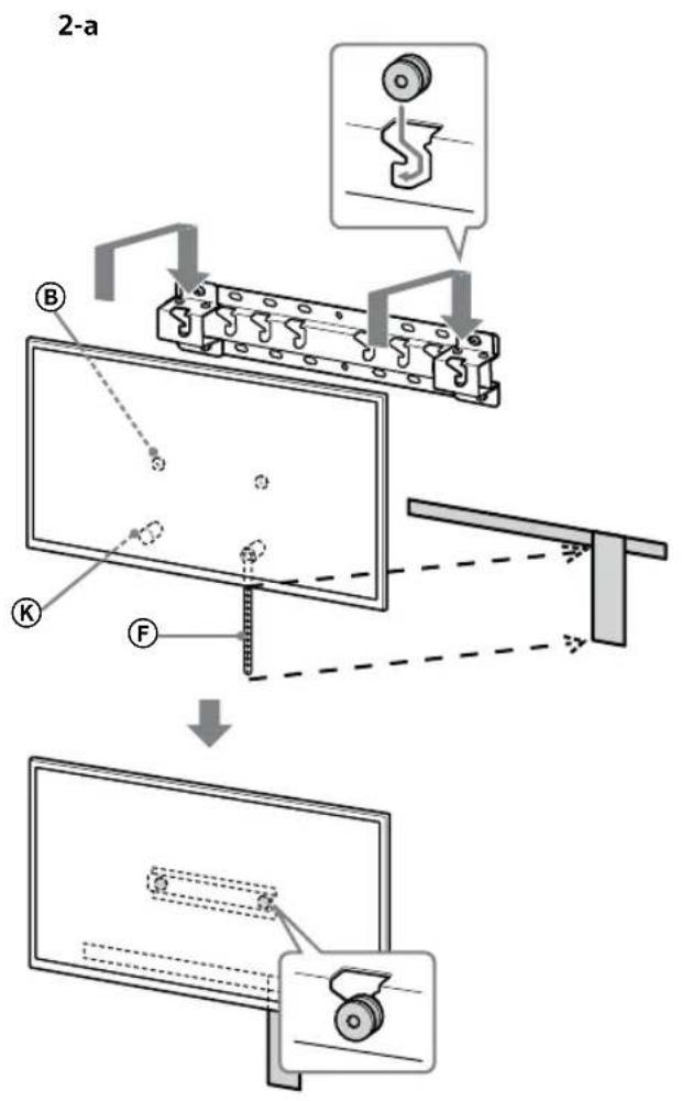
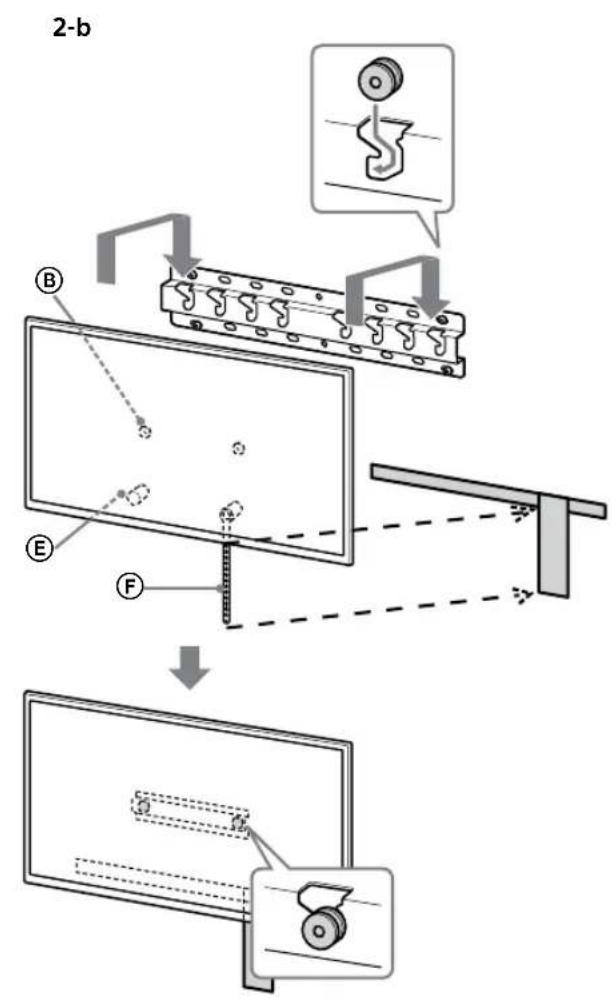
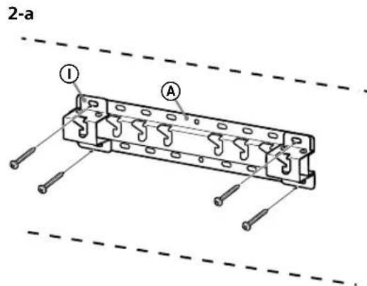
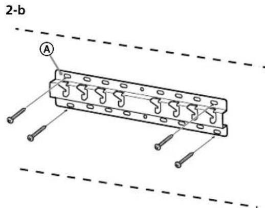
2 Select Wall mounting style. It is selectable as shown below.
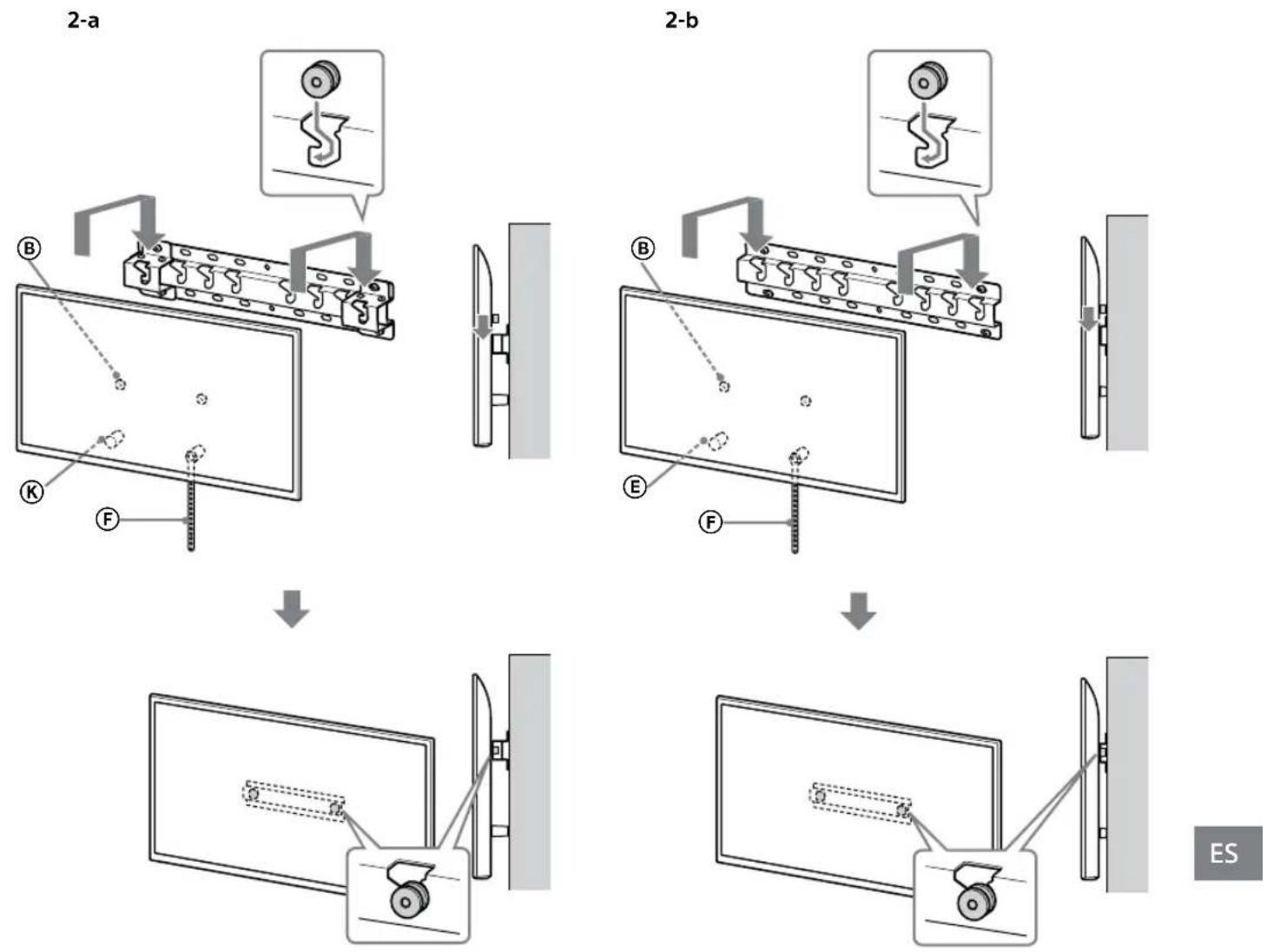
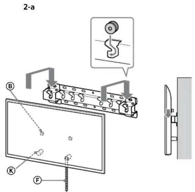
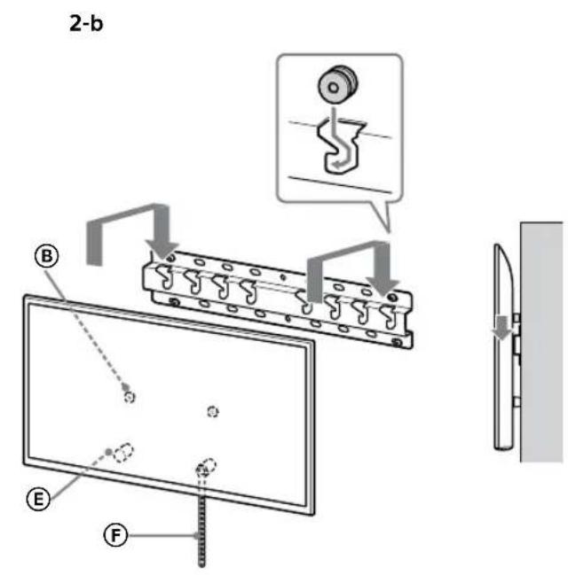
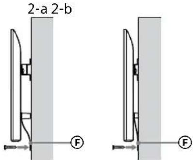
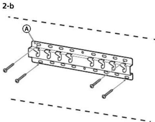
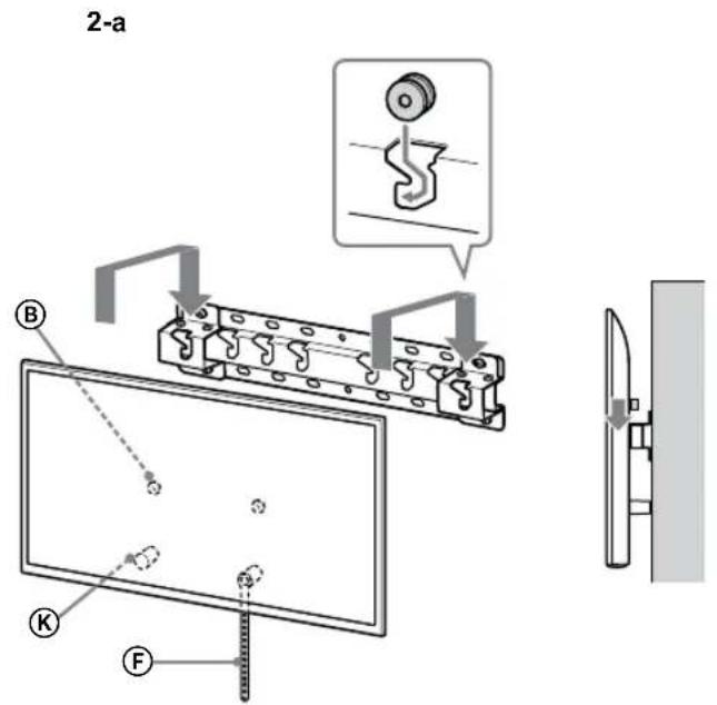
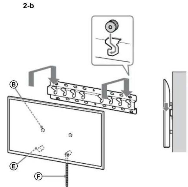
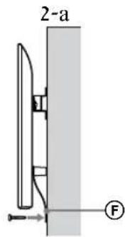
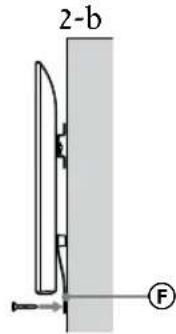
2-a Standard mount 2-b Slim mount
Refer to the table of step 1.
WARNING
- When 2-b is selected, rear terminal access is limited.
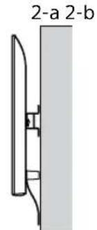
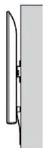
3 Refer to the below table about the Base Adaptor fitting location. In case of selecting 2-b, then skip this step.
| Model Name Hook location | |
| KD-75XG80□□ | |
| KD-65XG81□□ | b |
| KD-65XG80□□ | |
| KD-55XG81□□ | |
| KD-55XG80□□ | c |
| KD-49XG81□□ | |
| KD-49XG80□□ | |
| KD-43XG81□□ | d |
| KD-43XG80□□ | |
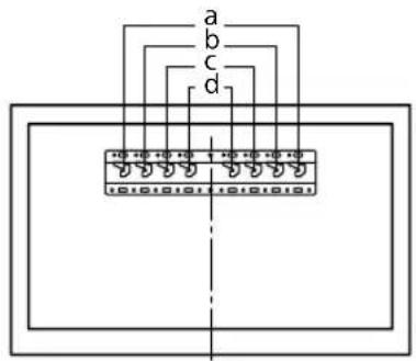
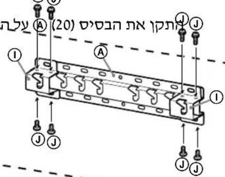
Fit Base Adaptor ① by using Screw (PSW 4x10) ② to Base (20) ③ when selecting 2-a.
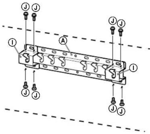
4 Decide the positions of the screws for installing the Base (20) Ⓐ.
Refer to the specifications on page 19. When selecting 2-a, please use the hole positions of Base Adaptor ①.
WARNING
- The wall that the TV will be mounted on should be able to support a weight of at least four times that of the TV (Refer to your TV's Reference Guide for its weight.).
- Determine the strength of the wall the TV will be mounted on. Reinforce the wall sufficiently, if necessary.
Installing the Base on the wall
- Use four or more screws of 8 mm diameter or equivalent (not supplied).
- Fit four screws to the holes of Base Adaptor ① with Base (20) Ⓐ (2-a only). • Install the Base (20) Ⓐ on the wall horizontally.
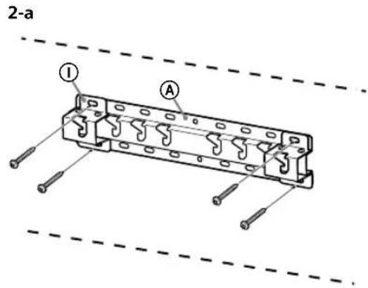
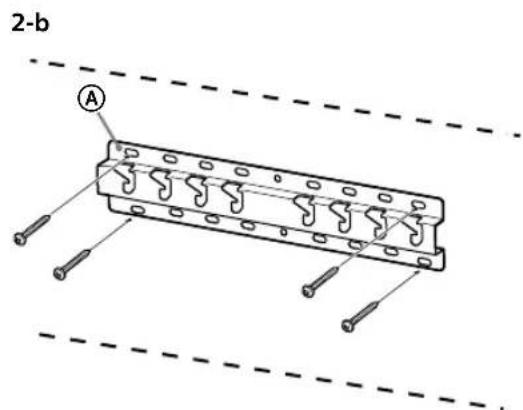
Preparing for the installation of the TV
Refer to the Setup Guide for stand installation.
KD-75XG80□□
1 Mark the installation location on the wall.
- Use masking tape, etc. (not supplied) to mark the location of the TV near the Base or Base Adaptor. Refer to the following table.
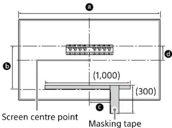
Unit: mm
| Model Name | Length for marking | Screen centre dimension | ||
| a | b | c | d | |
KD-75XG80□□ 1,686 564 150 202
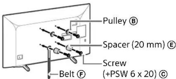
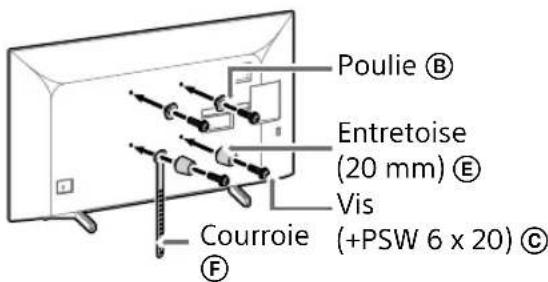
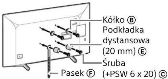
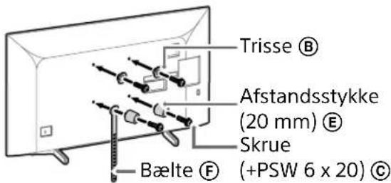
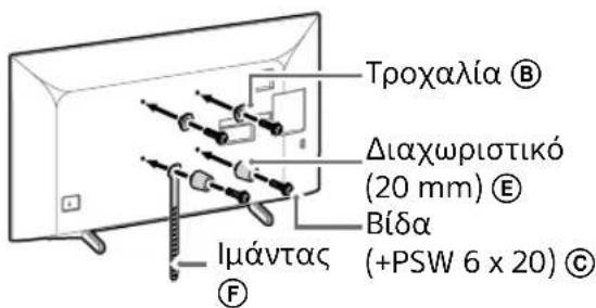
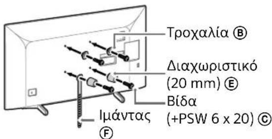
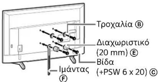
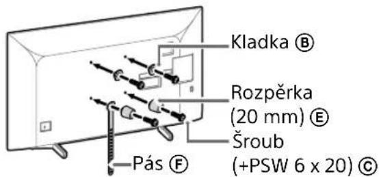
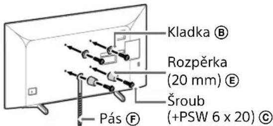
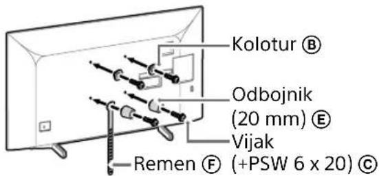
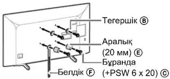
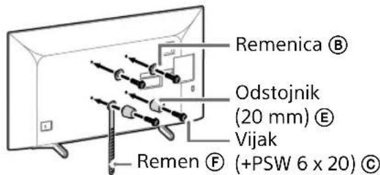
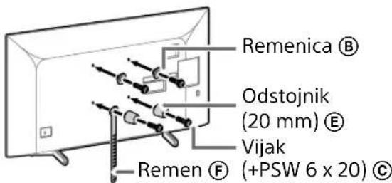
2 Attach the Attachment parts for Wall-Mount Bracket. Check the Attachment parts by referring to "Supplied with SU-WL450" in "Checking the parts" on page 5.
Note
- Firmly secure the Attachment parts using screws.
- When using an electric screwdriver, set the torque setting to approximately 1.5 N·m {15 kgf·cm}.
- Be sure to store the used or unused parts in a safe place for future use. Retain this manual for future reference.
Standard mounting (2-a)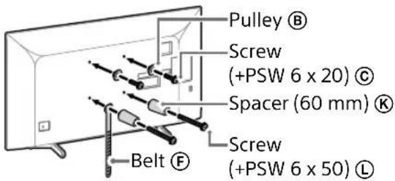
Slim mounting (2-b)
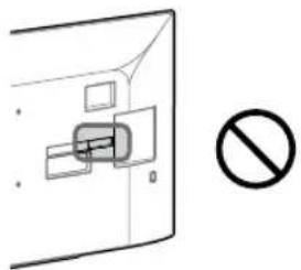
Note
- You cannot use some of the terminals on the rear of the TV when using this mounting style.
3 Connect the necessary cable(s) to the TV.
Make sure to connect the cables before installing the TV on the wall. You will be unable to connect the cables when the TV is installed.
Refer to the Reference Guide supplied with your TV.
Note
- Subcontract the cable routing in the wall to a licensed contractor.
- Bundle the connecting cables to prevent stepping on them before wall mounting.
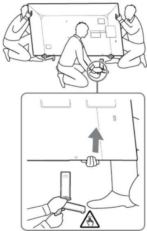
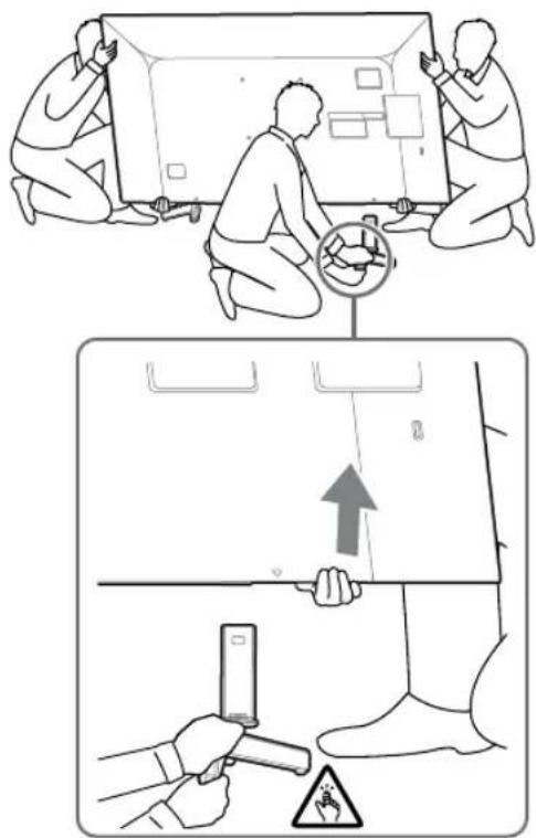
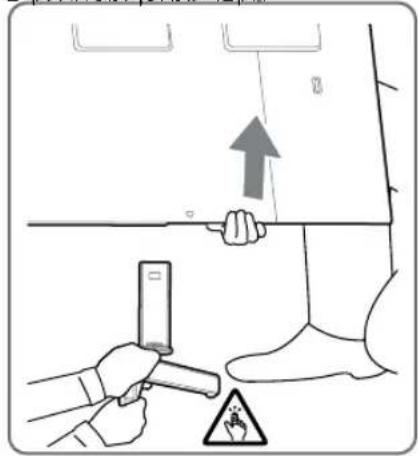
4 Detach the Table-Top Stand from the TV.
- Remove one side of the Table-Top Stand at a time. Firmly hold the Table-Top Stand securely with both hands while the other people lift up the TV.
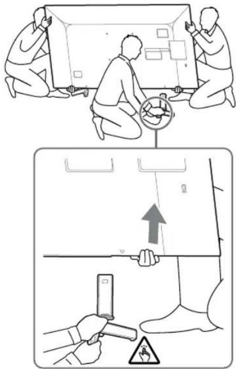
- Repeat the previous step and remove the other side of the Table-Top Stand.
Note
- Three or more people are required to detach the Table-Top Stand.
- Be careful not to use excessive force while detaching the Table-Top Stand from the TV as it may cause the TV set to fall resulting in personal injury or physical damage to the TV. • Take care when handling the Table-Top Stand to prevent damage to the TV.
- Be careful when lifting the TV as the Table-Top Stand is detached, the Table-Top Stand may topple over and cause personal injury. • Take care when removing the Table-Top Stand from the TV to prevent it from falling over and damaging the surface that the TV is sitting on.
KD-65XG81□□ / 65XG80□□
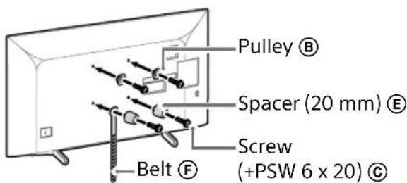
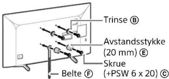
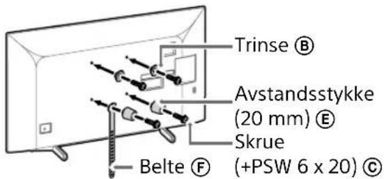
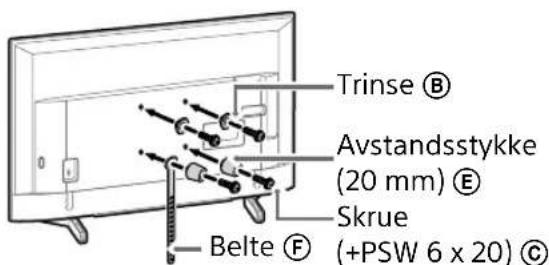
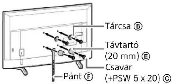
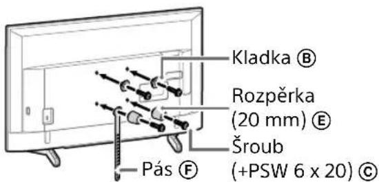
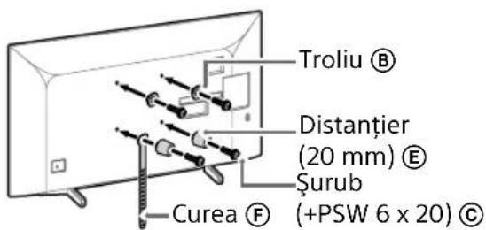
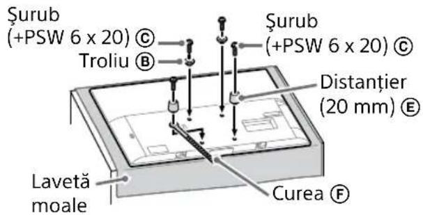
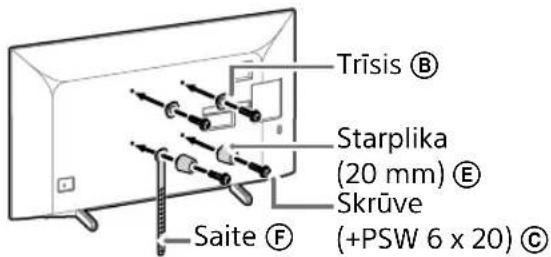
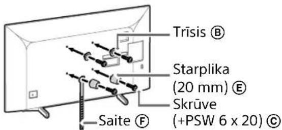
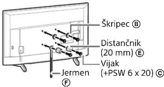
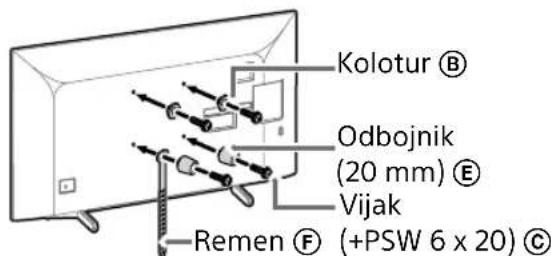
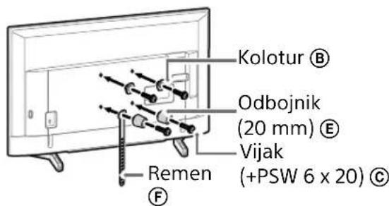
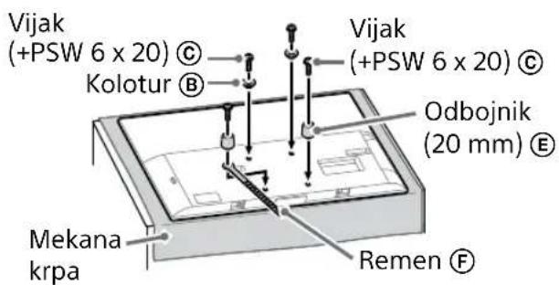
1 Attach the Attachment parts for Wall-Mount Bracket. Check the Attachment parts by referring to "Supplied with SU-WL450" in "Checking the parts" on page 5.
Note
- Firmly secure the Attachment parts using screws.
- When using an electric screwdriver, set the torque setting to approximately 1.5 N·m {15 kgf·cm}.
- Be sure to store the used or unused parts in a safe place for future use. Retain this manual for future reference.
Standard mounting (2-a)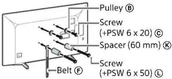
Slim mounting (2-b)
Note
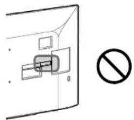
- You cannot use some of the terminals on the rear of the TV when using this mounting style.
2 Connect the necessary cable(s) to the TV.
Make sure to connect the cables before installing the TV on the wall. You will be unable to connect the cables when the TV is installed.
Refer to the Reference Guide supplied with your TV.
Note
- Subcontract the cable routing in the wall to a licensed contractor.
- Bundle the connecting cables to prevent stepping on them before wall mounting.
3 Detach the Table-Top Stand from the TV.
- Remove one side of the Table-Top Stand at a time. Firmly hold the Table-Top Stand securely with both hands while the other people lift up the TV.
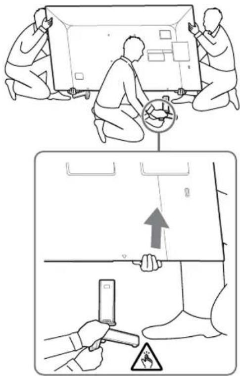
- Repeat the previous step and remove the other side of the Table-Top Stand.
Note
- Three or more people are required to detach the Table-Top Stand.
- Be careful not to use excessive force while detaching the Table-Top Stand from the TV as it may cause the TV set to fall resulting in personal injury or physical damage to the TV. • Take care when handling the Table-Top Stand to prevent damage to the TV.
- Be careful when lifting the TV as the Table-Top Stand is detached, the Table-Top Stand may topple over and cause personal injury. • Take care when removing the Table-Top Stand from the TV to prevent it from falling over and damaging the surface that the TV is sitting on.
KD-55XG81□□/
55XG80□□
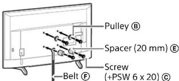
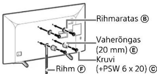
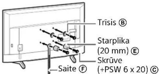
1 Attach the Attachment parts for Wall-Mount Bracket. Check the Attachment parts by referring to "Supplied with SU-WL450" in "Checking the parts" on page 5.
Note
- Firmly secure the Attachment parts using screws.
- When using an electric screwdriver, set the torque setting to approximately 1.5 N·m {15 kgf·cm}.
- Be sure to store the used or unused parts in a safe place for future use. Retain this manual for future reference.
Standard mounting (2-a)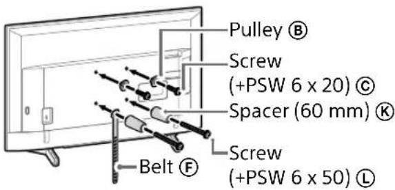
Slim mounting (2-b)
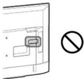
Note
- You cannot use some of the terminals on the rear of the TV when using this mounting style.
2 Connect the necessary cable(s) to the TV.
Make sure to connect the cables before installing the TV on the wall. You will be unable to connect the cables when the TV is installed.
Refer to the Reference Guide supplied with your TV.
Note
- Subcontract the cable routing in the wall to a licensed contractor.
- Bundle the connecting cables to prevent stepping on them before wall mounting.
3 Detach the Table-Top Stand from the TV.
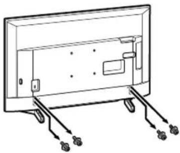
Note
- Be careful when lifting the TV as the Table-Top Stand is detached, the Table-Top Stand may topple over and cause personal injury. • Take care when removing the Table-Top Stand from the TV to prevent it from falling over and damaging the surface that the TV is sitting on.
KD-49XG81□□/
49XG80□□ / 43XG81□□ /
43XG80□□
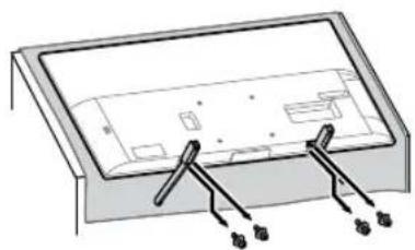
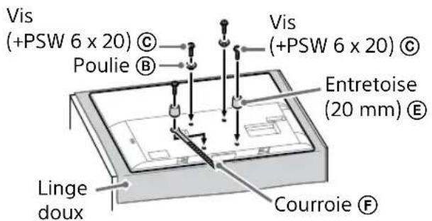
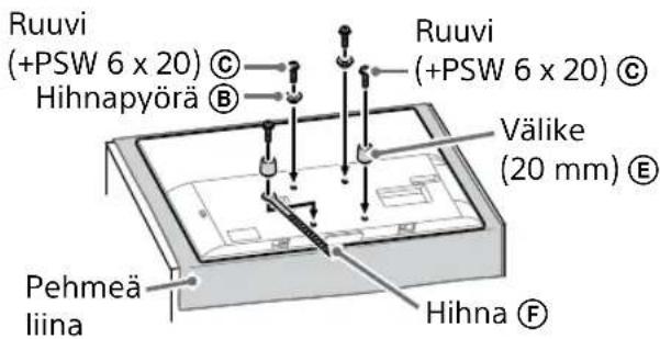
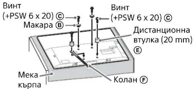
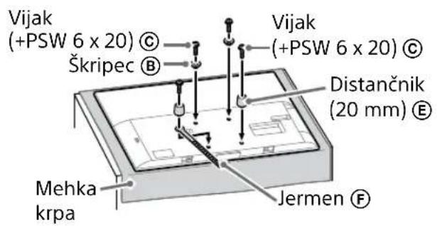
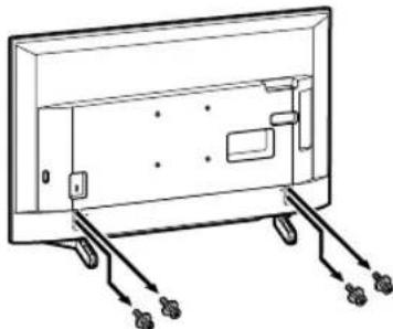
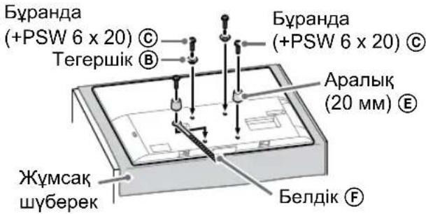
1 Detach the Table-Top Stand from the TV.
Note
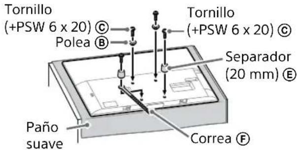
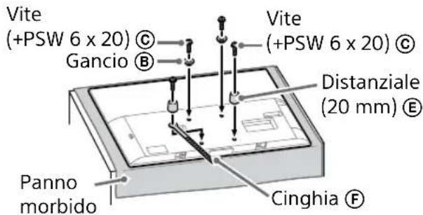
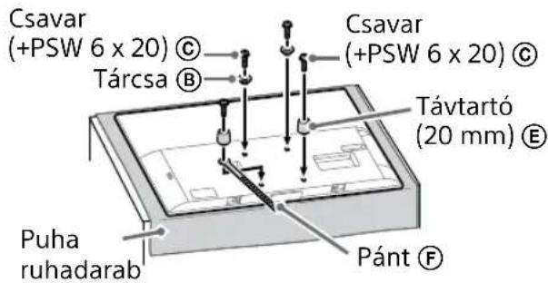
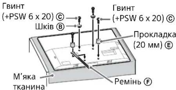
- Make sure to place the TV on a soft cloth to prevent damaging the display's surface.
- When installing the Wall-Mount Bracket, do not use the screws removed from the Table-Top Stand.
- Be sure to store the removed Table-Top Stand and its screws in a safe place, keeping them away from children. You will need them if you want to use the TV on a table in the future. The Table-Top Stand cannot be purchased separately.
WARNING
- Be sure the TV is in the vertical position before switching it on. The TV set must not be powered on with the LCD panel face down to avoid uneven picture uniformity.
- If pressure or shock is applied to the surface of the TV, the TV may break or become damaged.
- Lay the TV face down on a stable and level surface with the Table-Top Stand hanging over the edge of the surface. Having the TV face and the base of the Table-Top Stand on the same level surface will create an unstable working condition and can damage the TV.
- When detaching the Table-Top Stand from the TV, hold the Table-Top Stand securely with both hands.
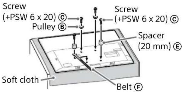
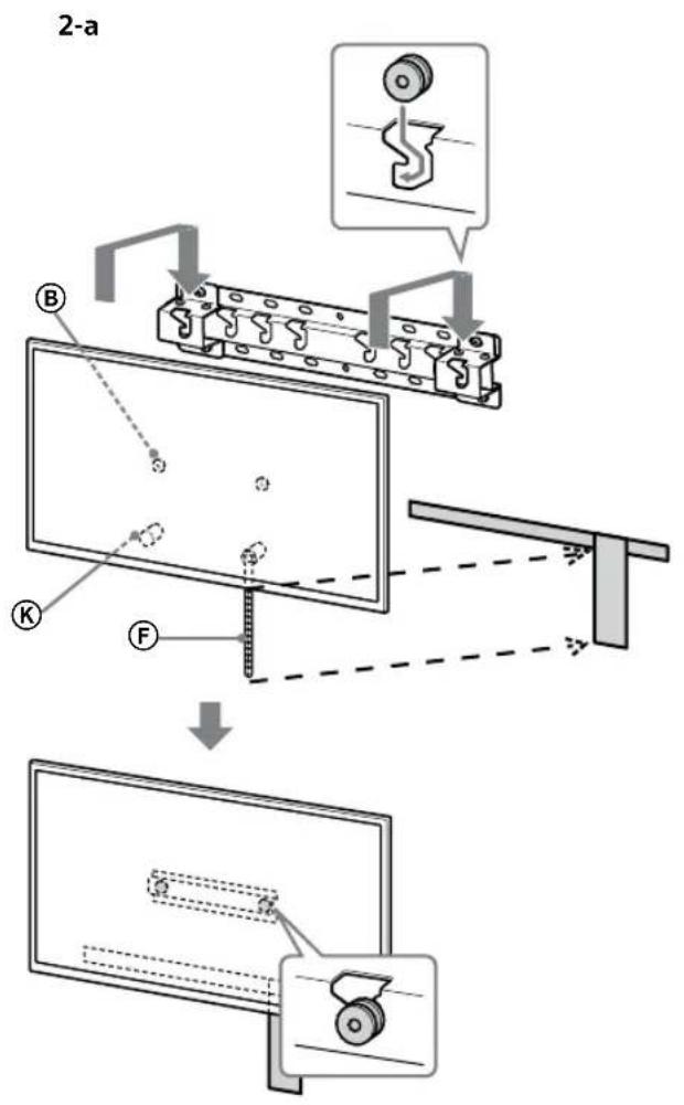
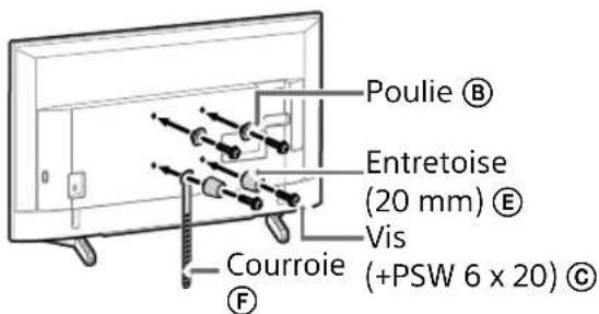
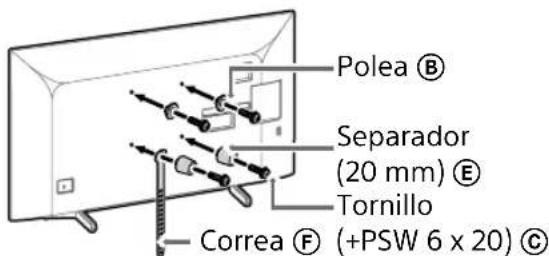
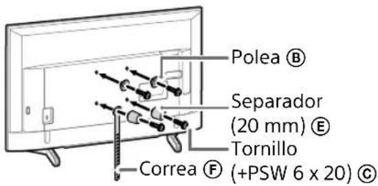
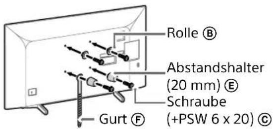
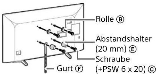
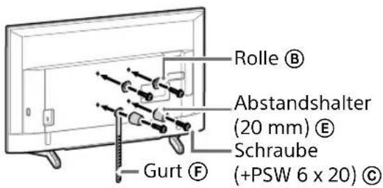
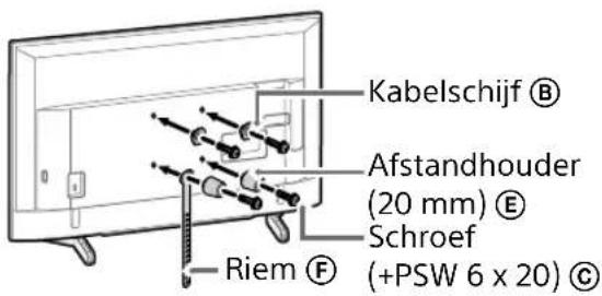
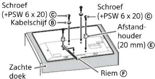
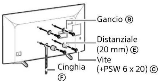
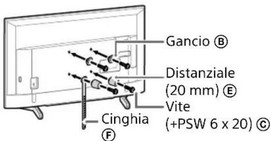
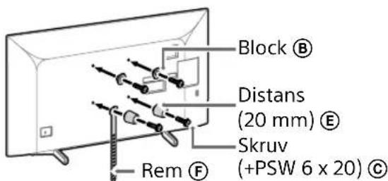
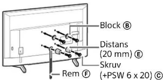
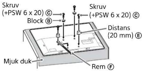
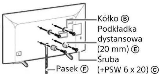
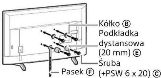
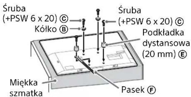
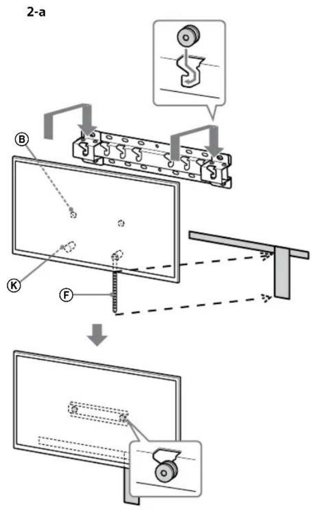
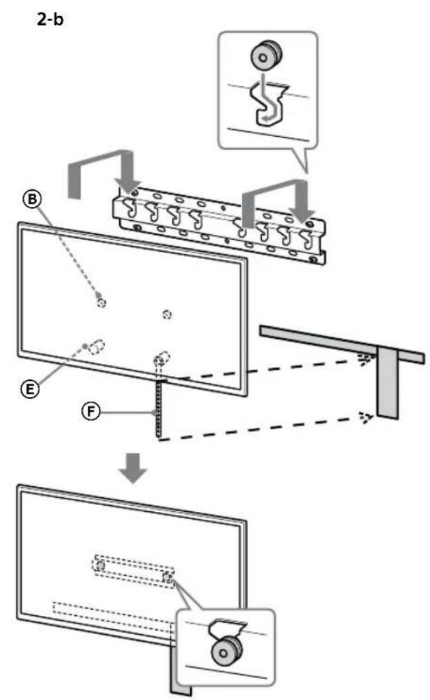
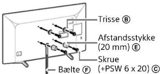
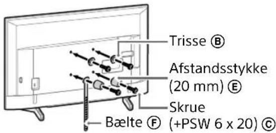
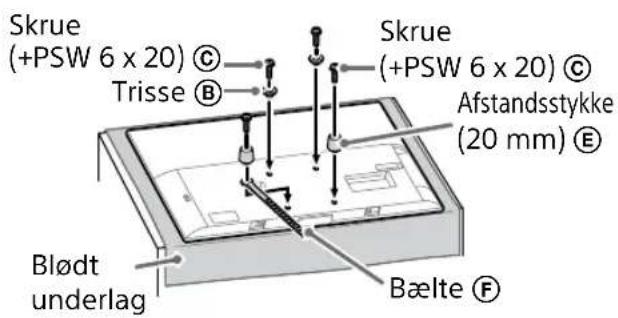
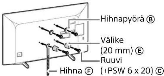
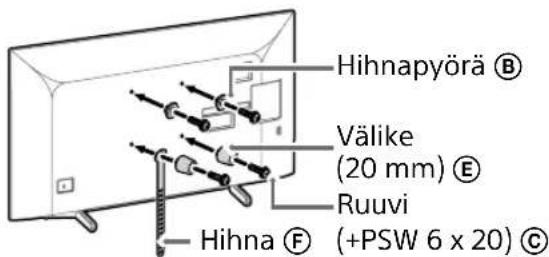
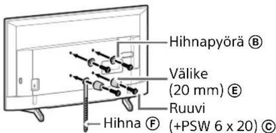
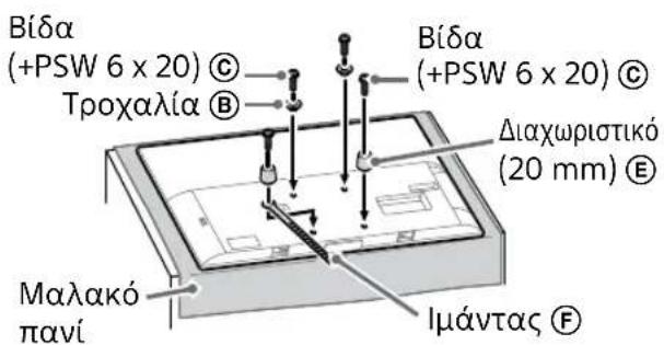
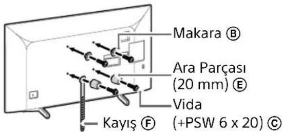
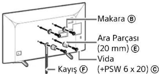
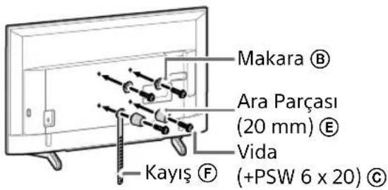
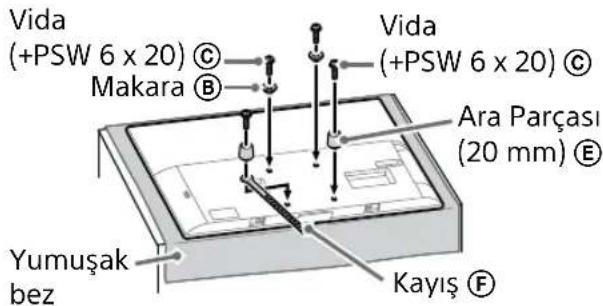
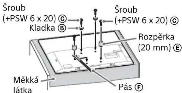
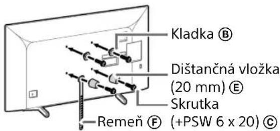
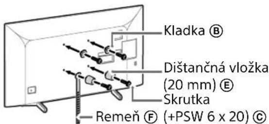
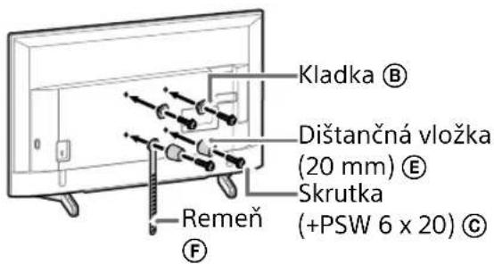
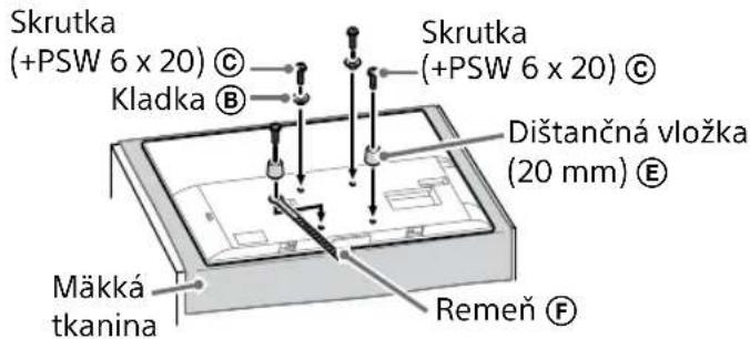
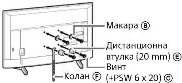
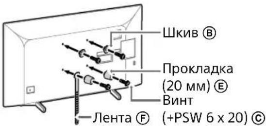
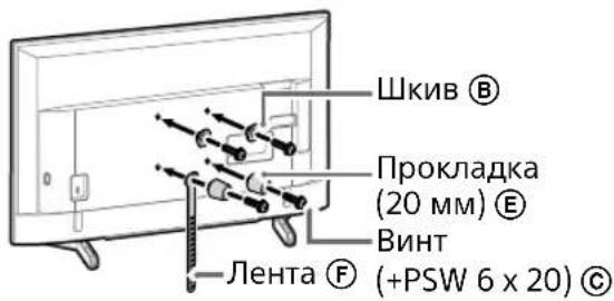
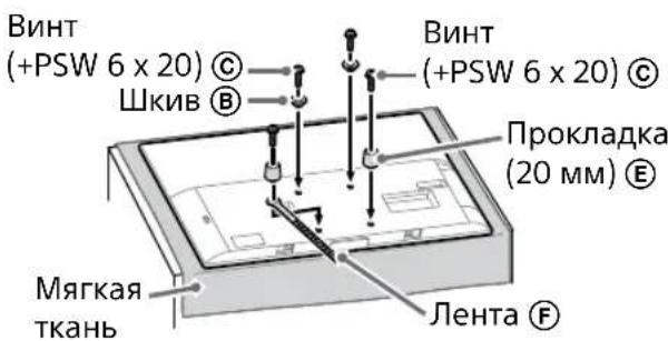
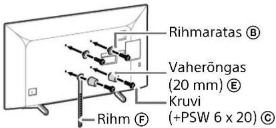
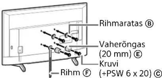
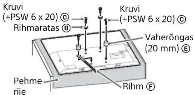
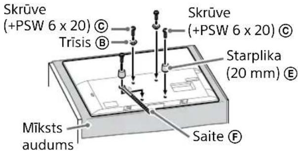
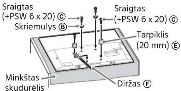
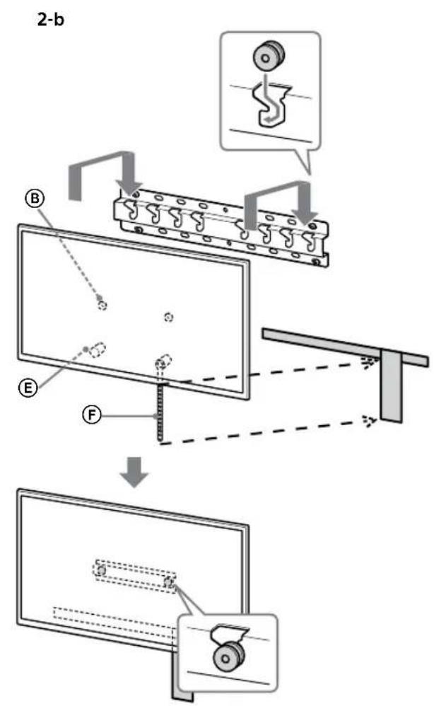
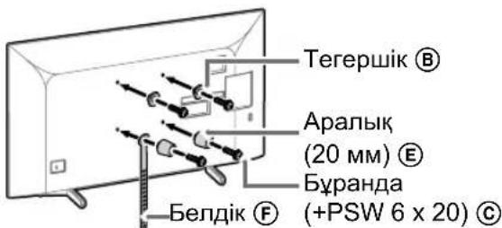
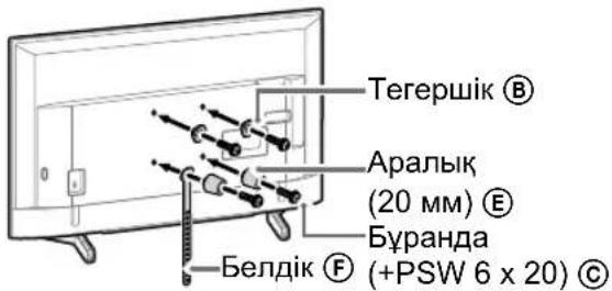
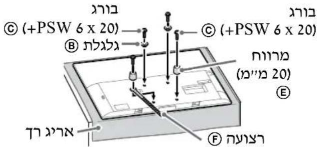
2 Attach the Attachment parts for the Wall-Mount Bracket. Check the Attachment parts by referring to "Supplied with SU-WL450" in "Checking the parts" on page 5.
Note
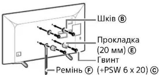
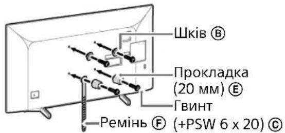
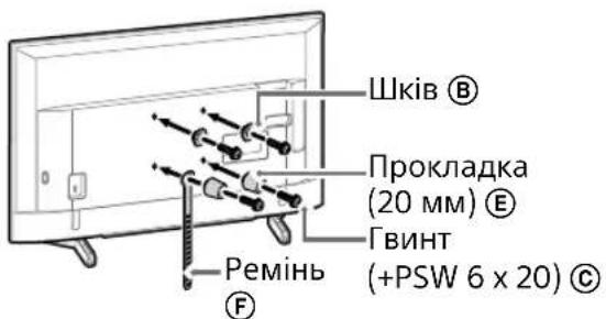
- Firmly secure the Attachment parts using screws.
- When using an electric screwdriver, set the torque setting to approximately 1.5 N·m {15 kgf·cm}.
- Be sure to store the used or unused parts in a safe place for future use. Retain this manual for future reference.
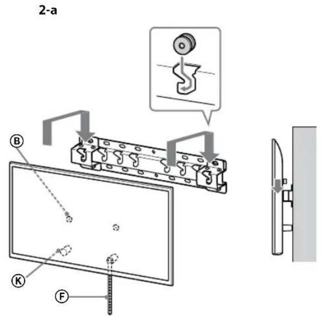
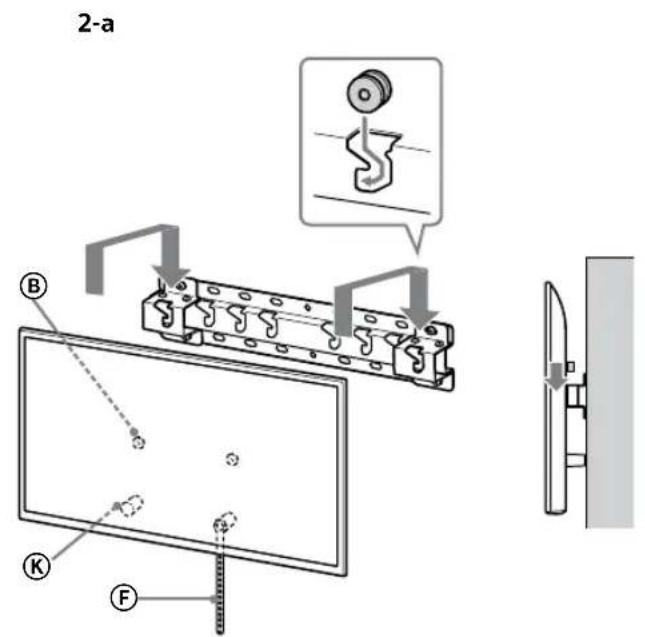
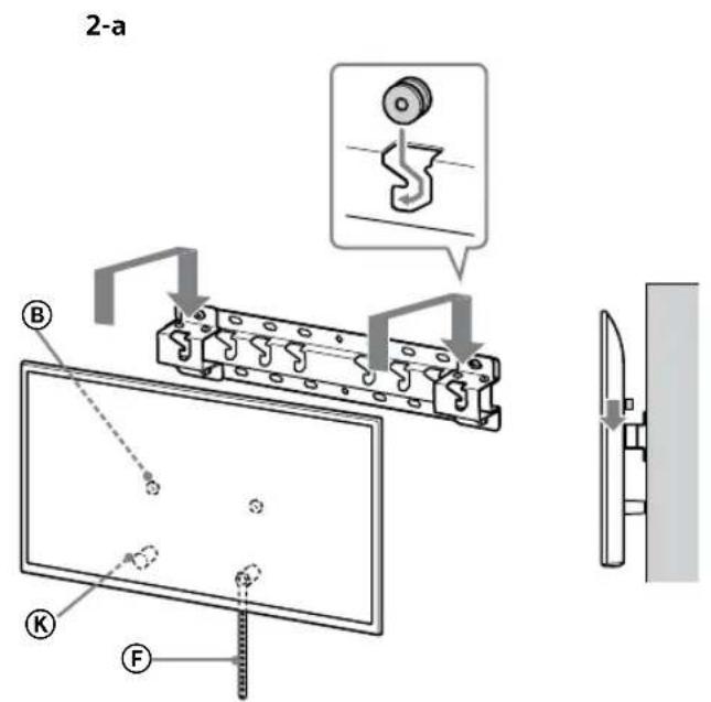
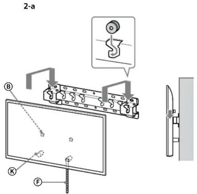
Standard mounting (2-a)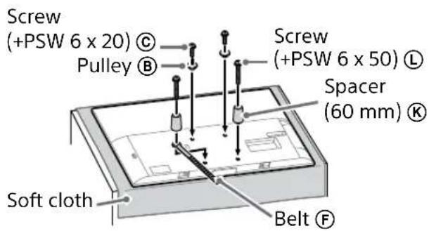
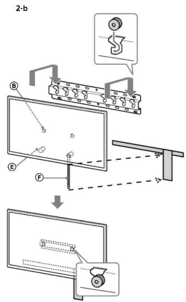
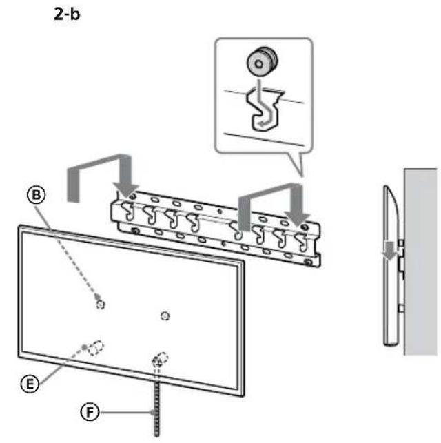
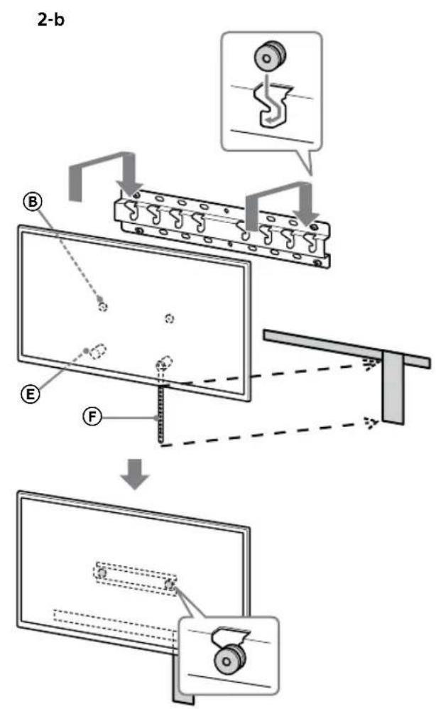
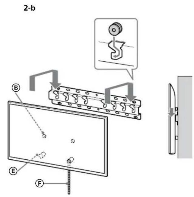
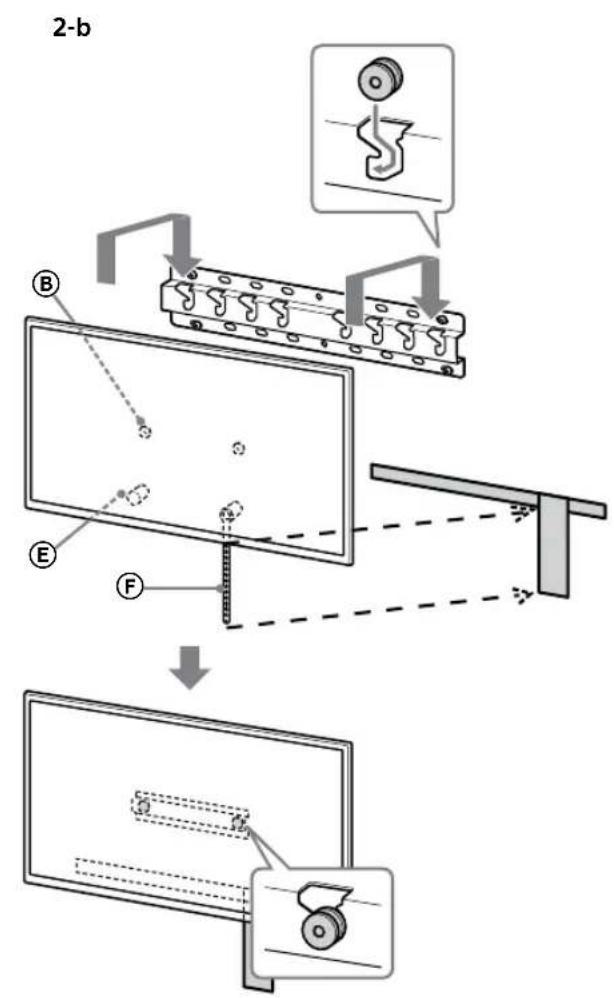
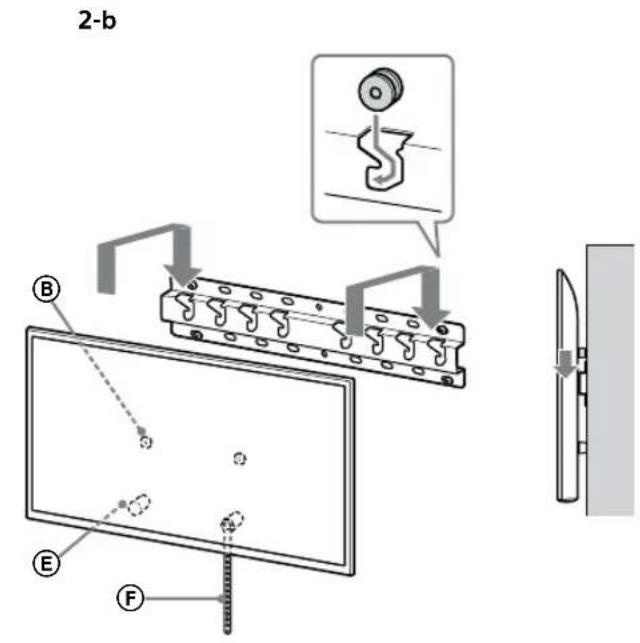
Slim mounting (2-b)
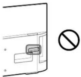
Note
- You cannot use some of the terminals on the rear of the TV when using this mounting style.
3 Connect the necessary cable(s) to the TV.
Make sure to connect the cables before installing the TV on the wall. You will be unable to connect the cables when the TV is installed.
Refer to the Reference Guide supplied with your TV.
Note
- Subcontract the cable routing in the wall to a licensed contractor.
- Bundle the connecting cables to prevent stepping on them before wall mounting.
Installing the TV on the wall
KD-75XG80□□
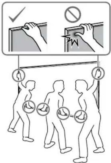
1 Lift the TV.
- For the location of the Pulleys Ⓑ to hang on the Base or Base Adaptor, refer to the table in step 3 of "Deciding on the installation location" on page 7. • Make sure that the rear of the TV touches the Base or Base Adaptor when holding the TV.
Note
- Hold the TV securely with both hands and make sure the Belt Ⓔ and the bottom of the TV align with the masking tape.
- Carry the TV with three people, and the person who is in front of the TV leads the others to adjust the position.
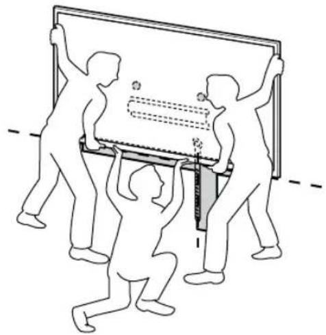
• Take great care when installing the TV to the wall, especially for the person who is supporting the TV from below. The television set may fall, causing serious bodily injury or even death.
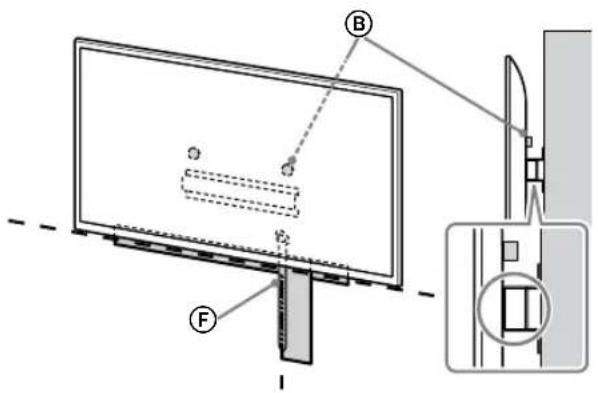
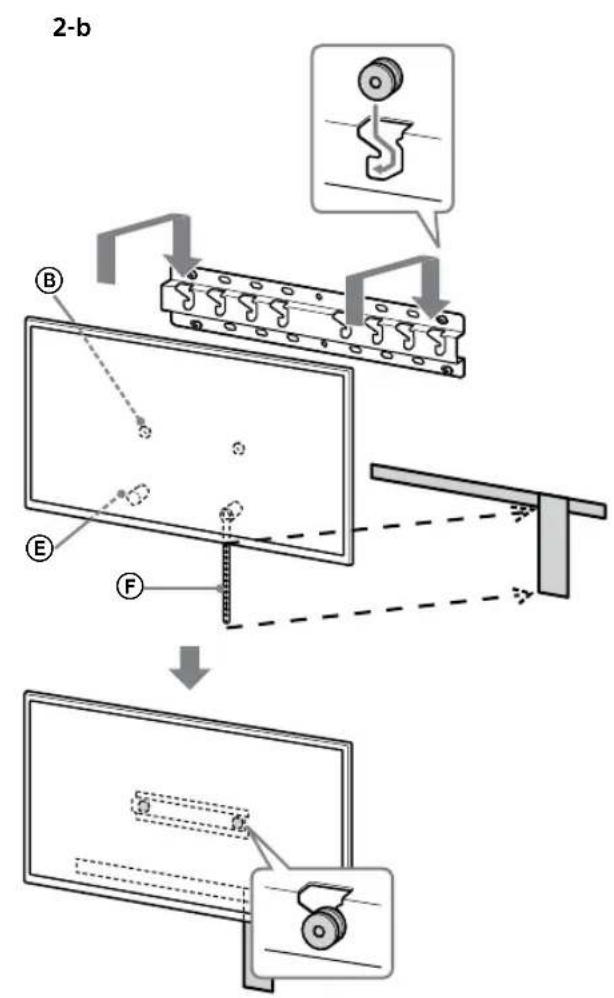
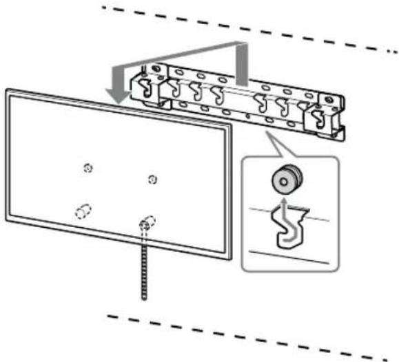
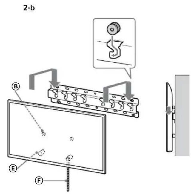
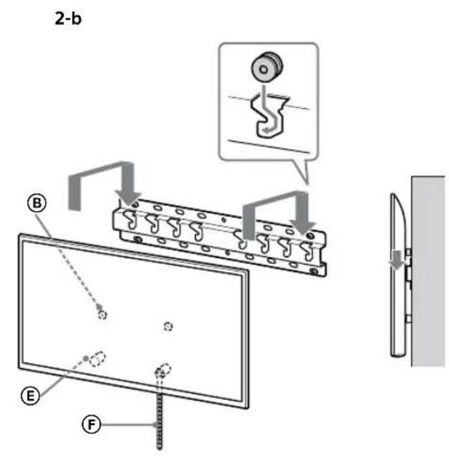
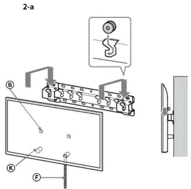
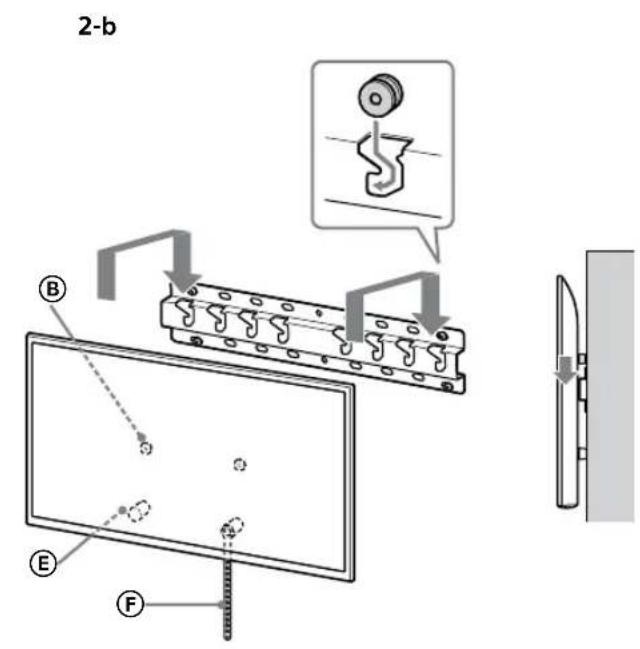
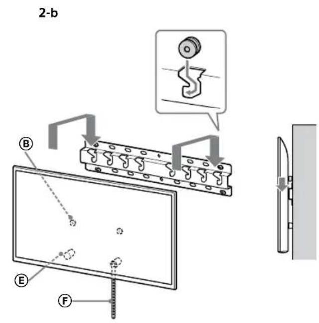
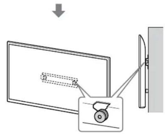
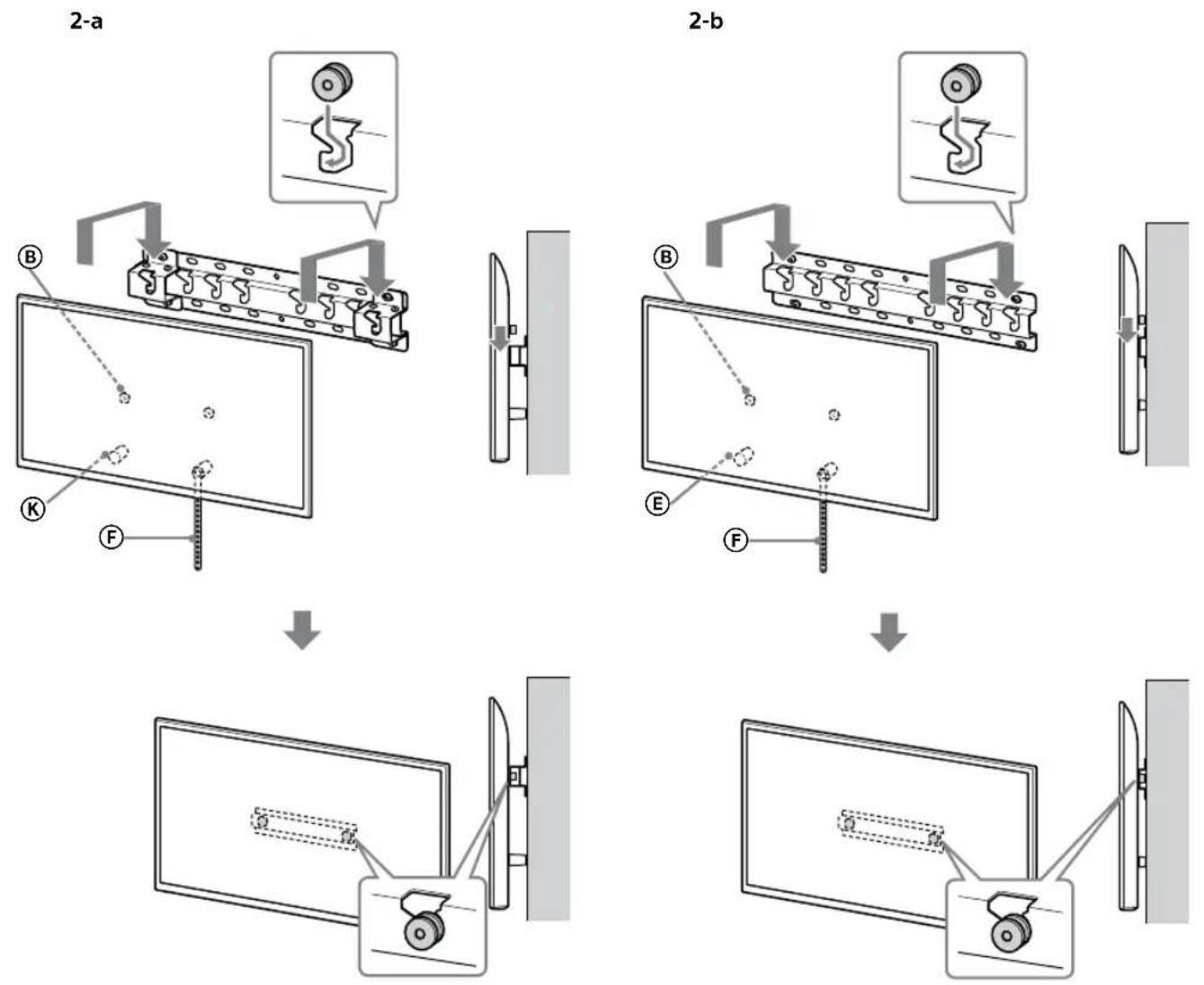
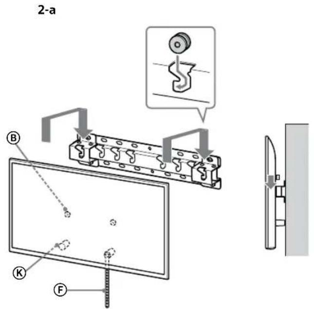
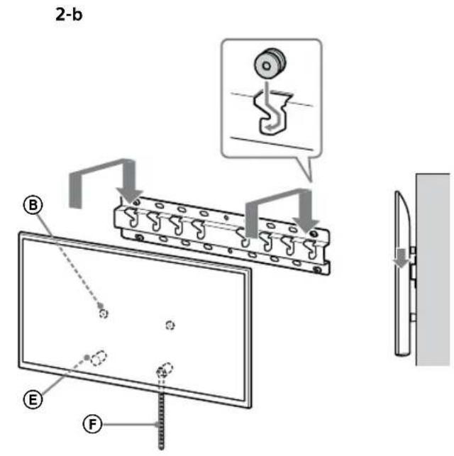
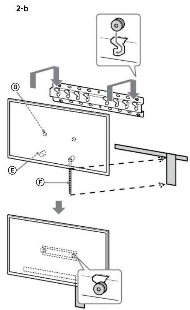
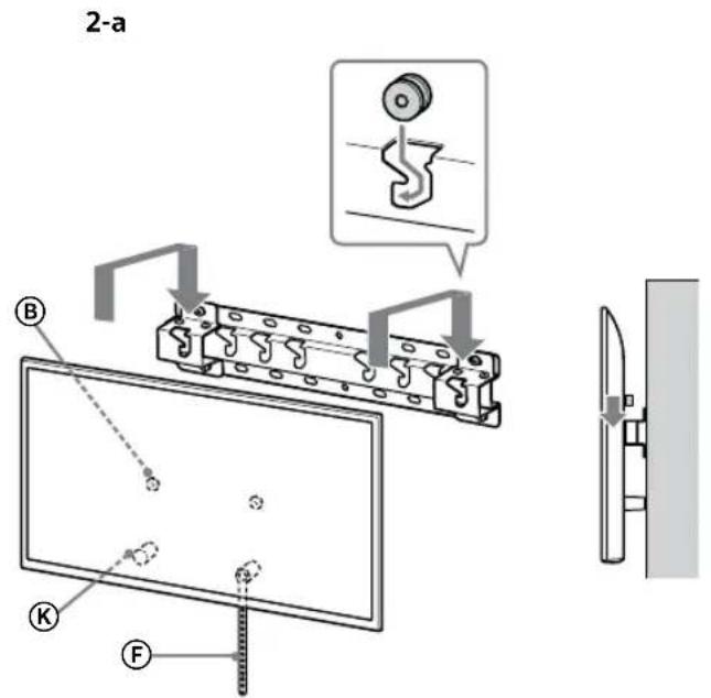
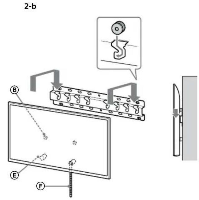
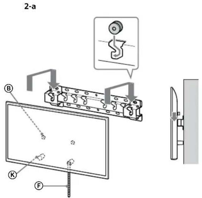
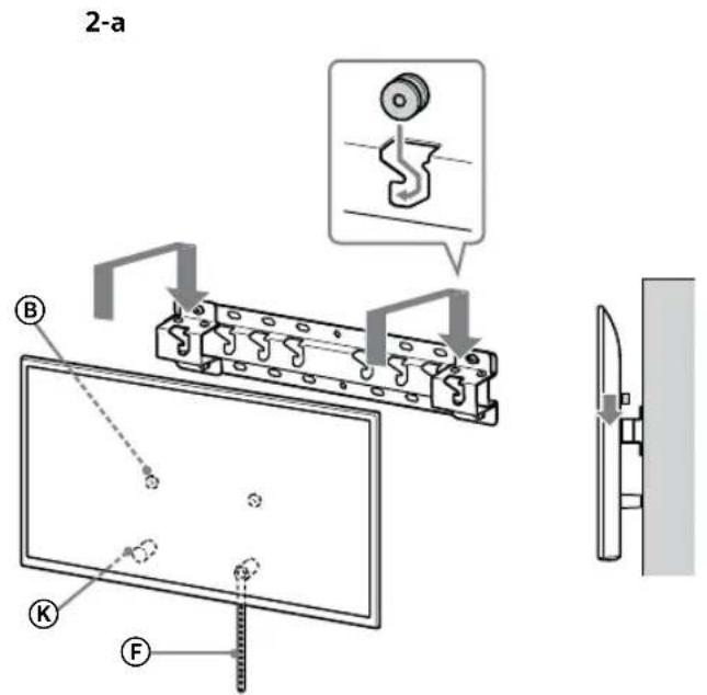
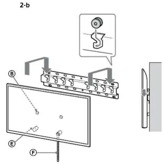
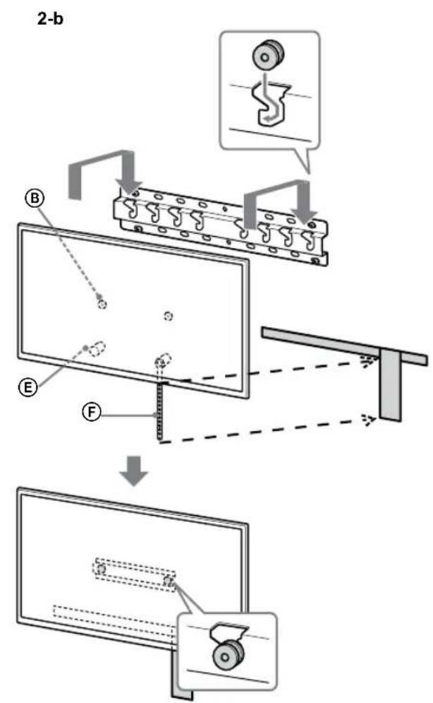
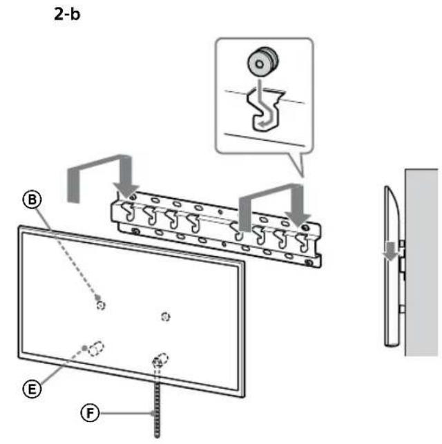
2 Install the TV onto the Base or Base Adaptor.
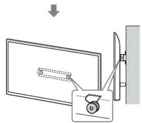
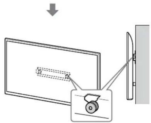
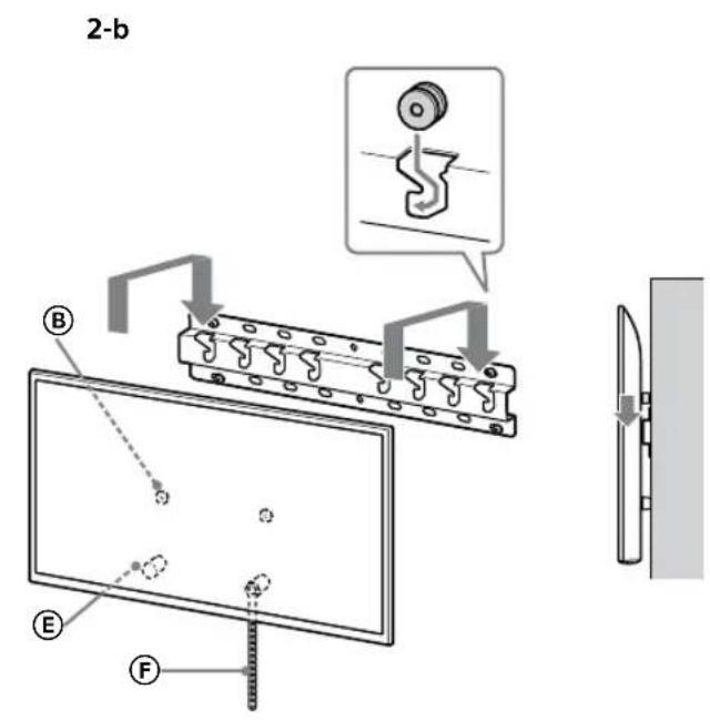
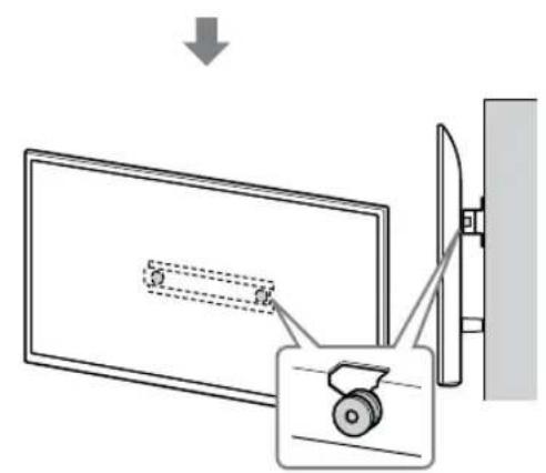
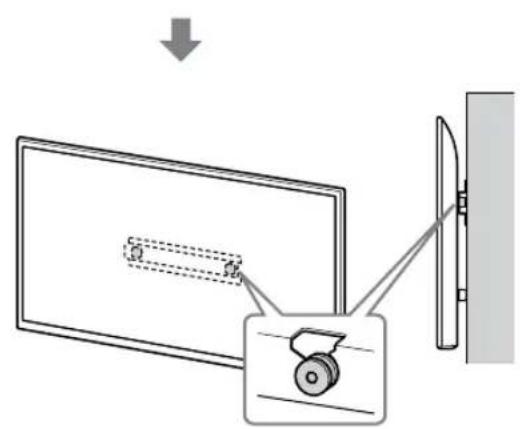
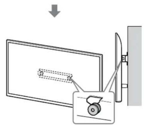
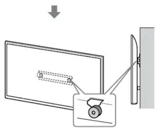
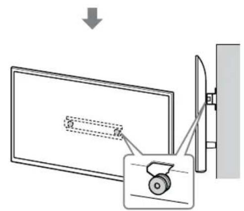
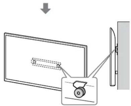
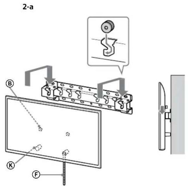
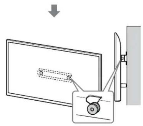
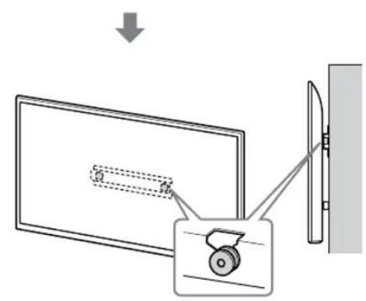
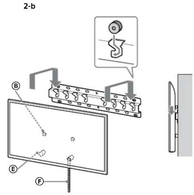
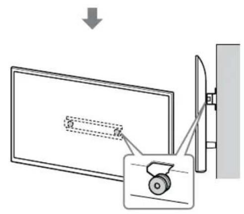
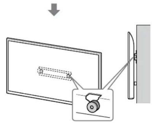
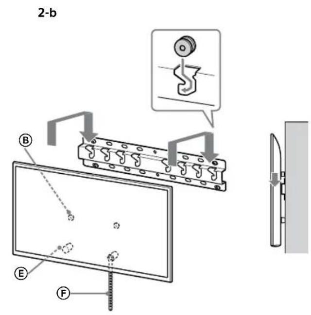
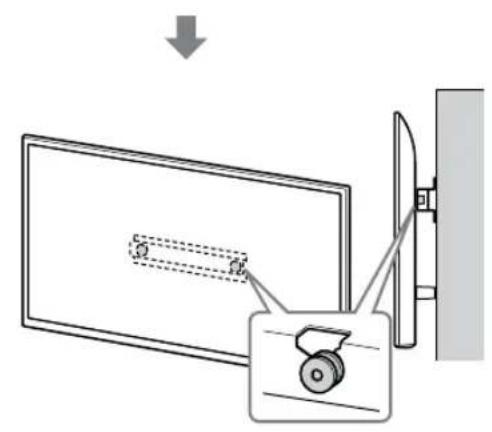
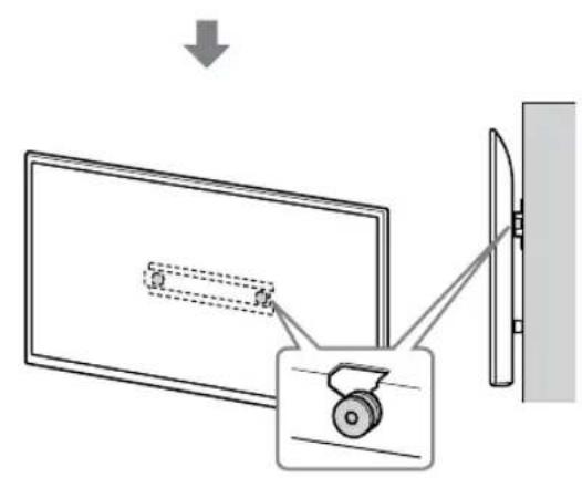
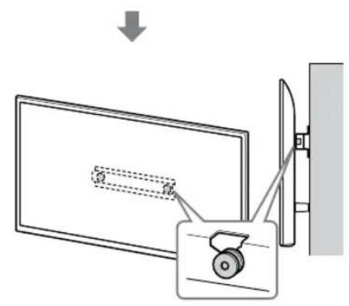
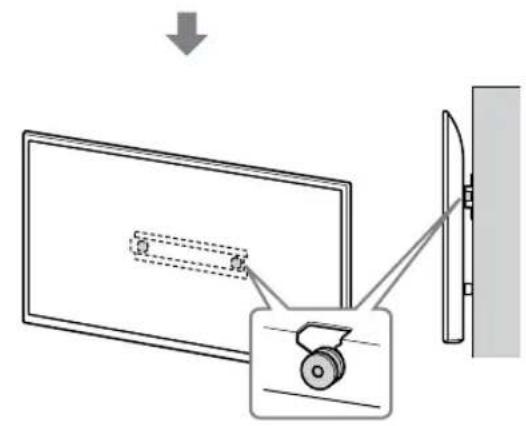
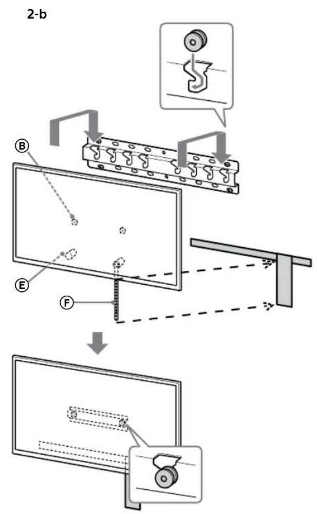
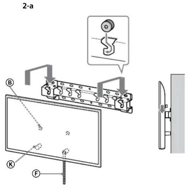
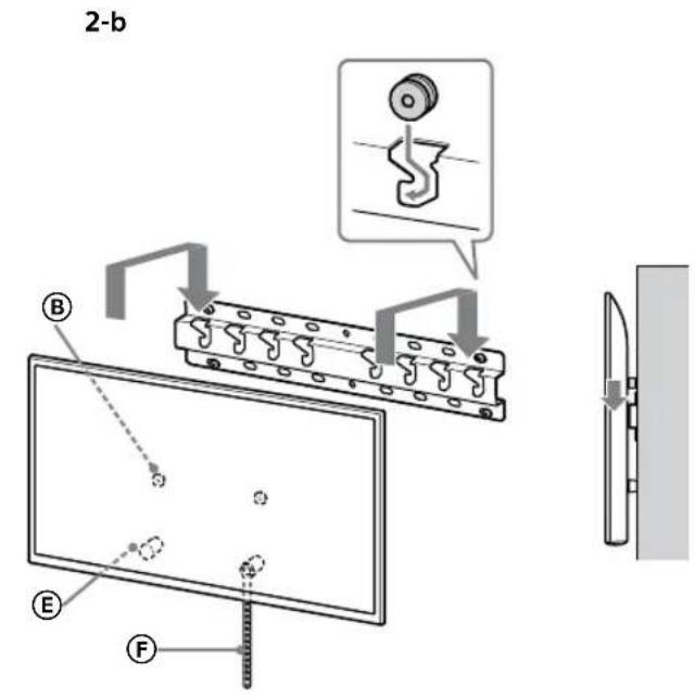
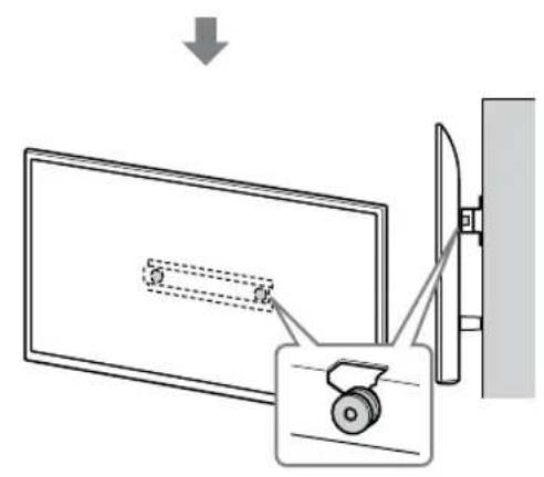
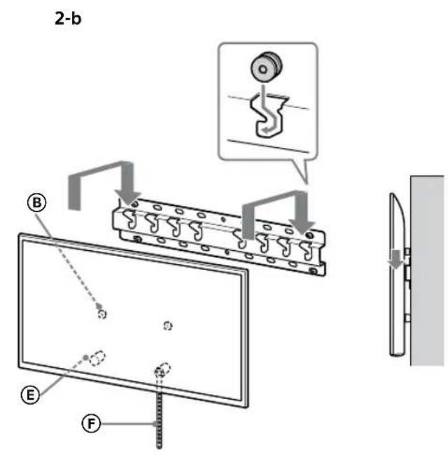
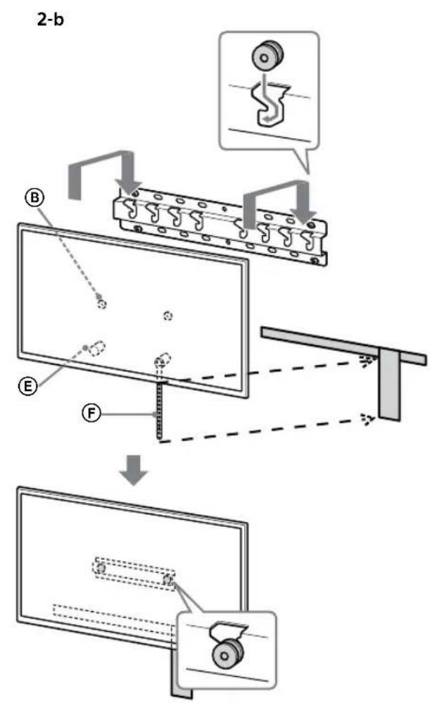
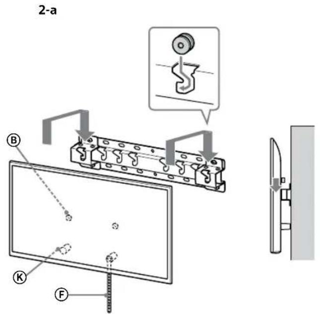
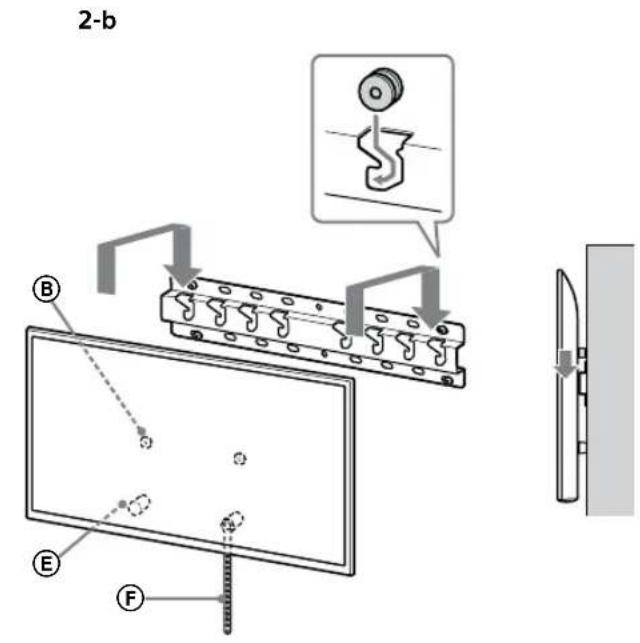
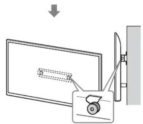
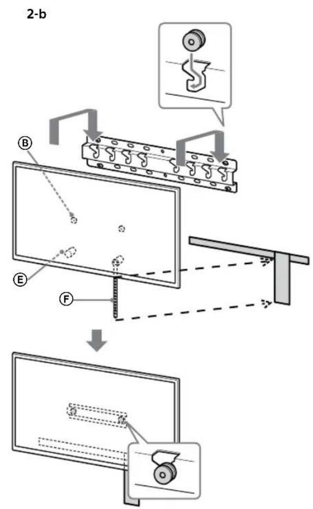
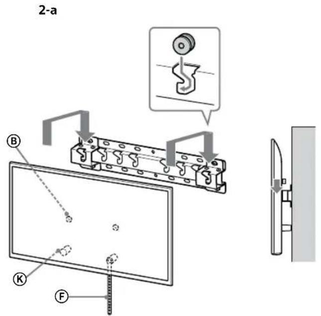
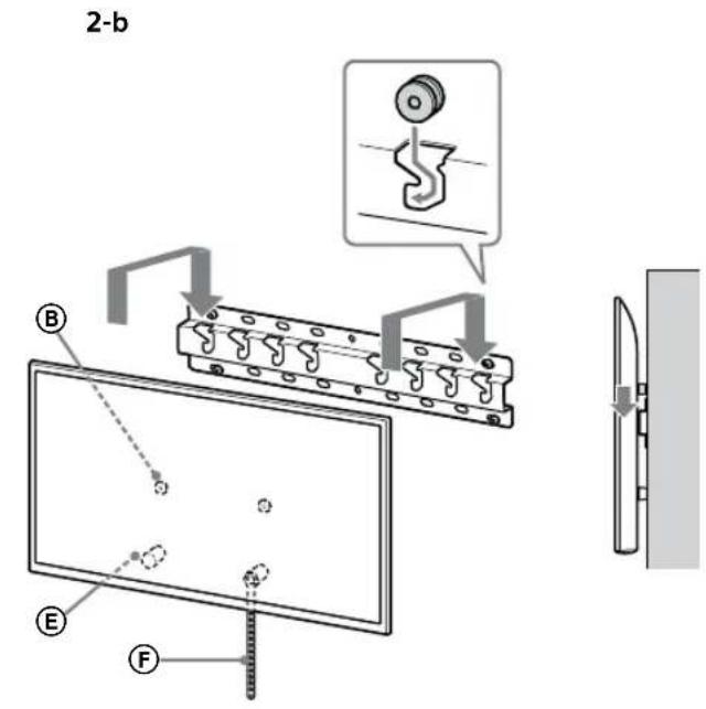
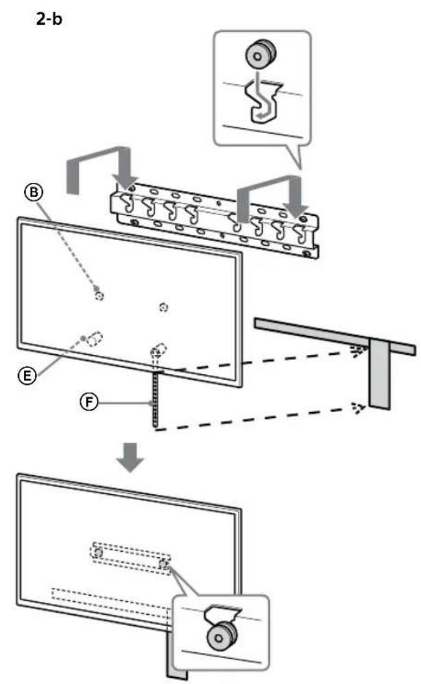
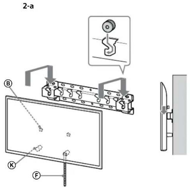
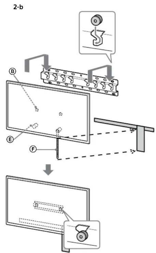
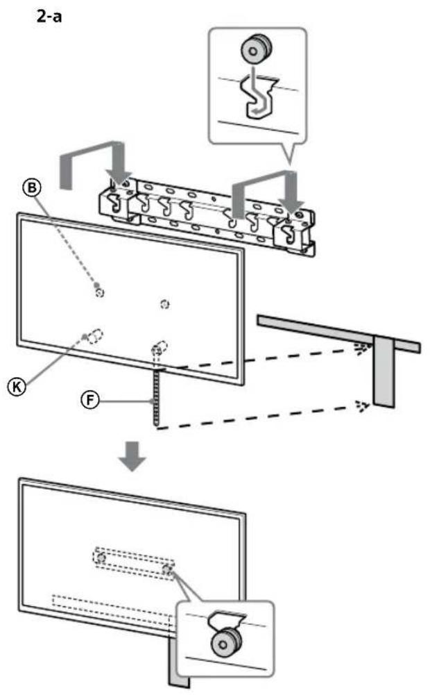
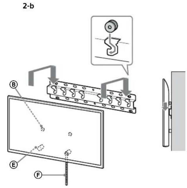
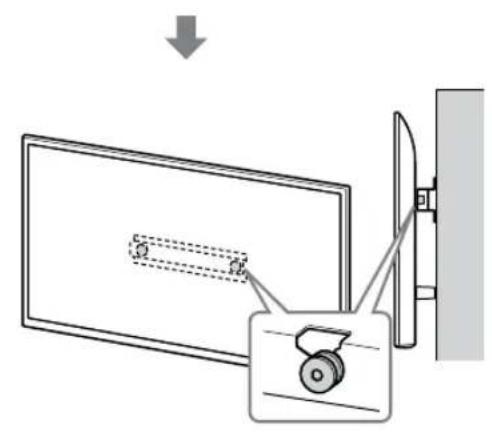
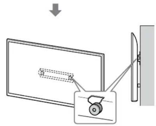
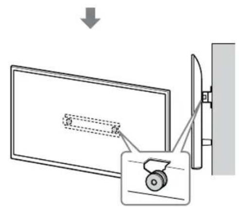
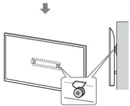
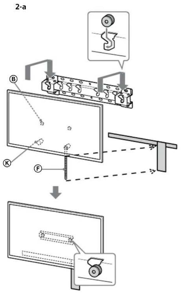
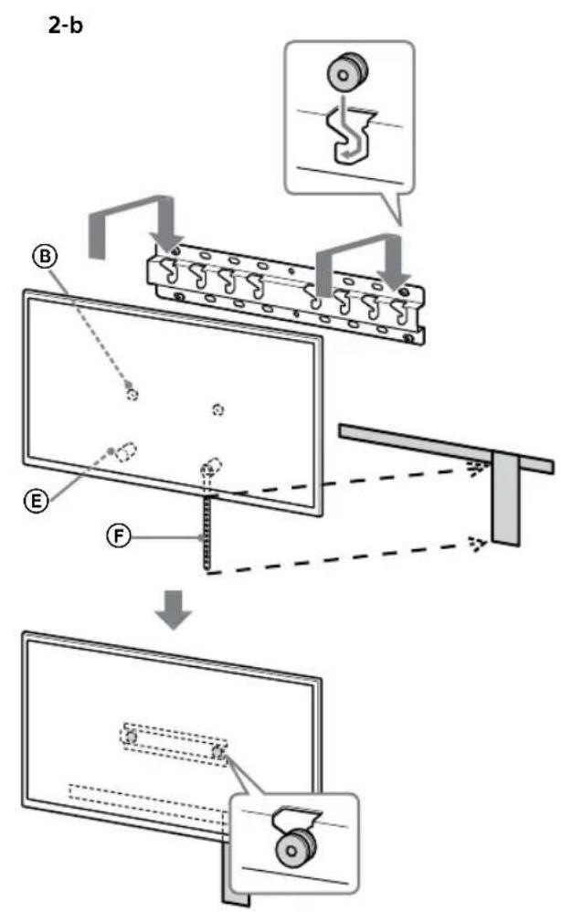
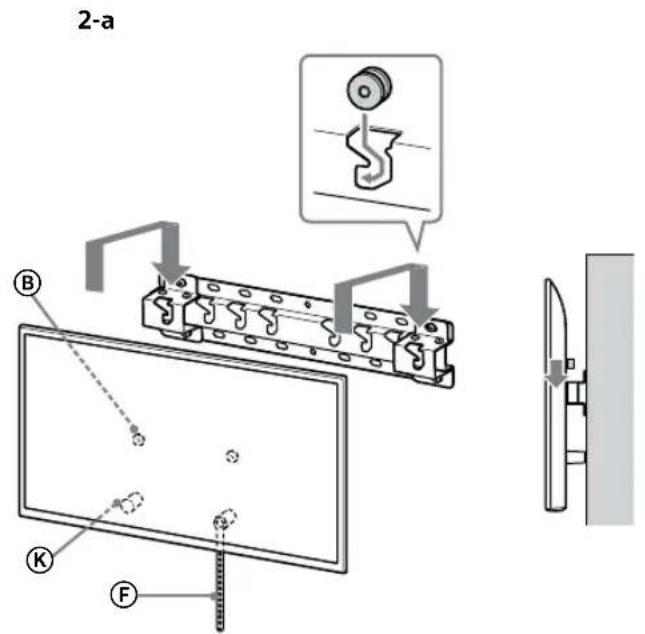
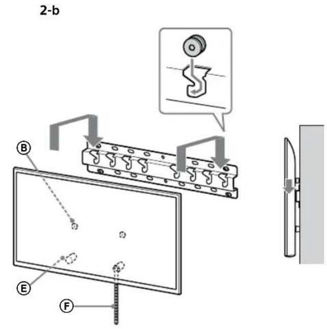
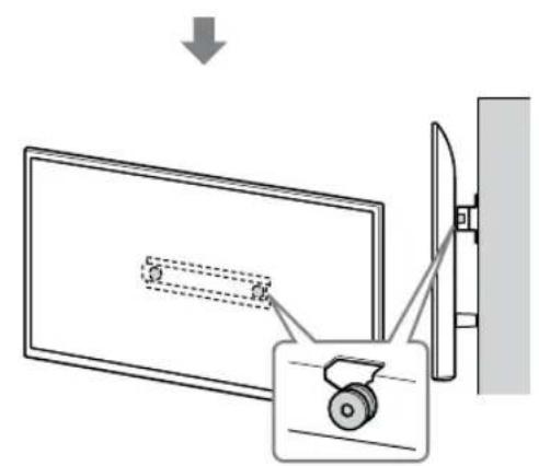
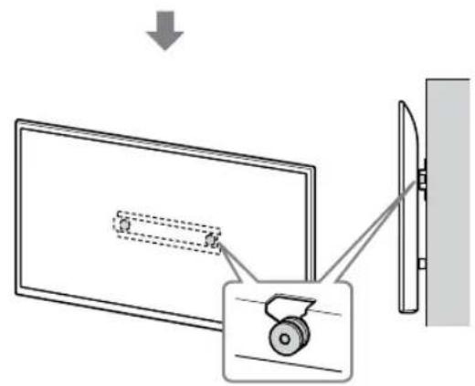
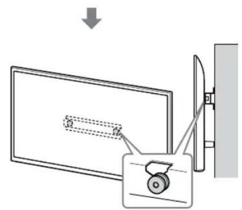
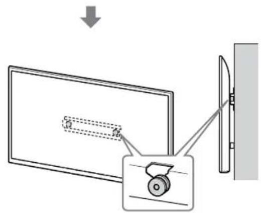
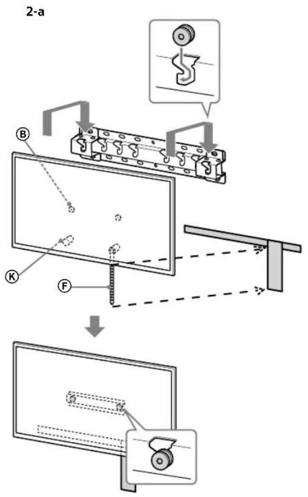
- Gently slide down the TV and hang the Pulleys ⑧ attached to the rear of the TV onto the Base or Base Adaptor, making sure to confirm the shape of the holes.
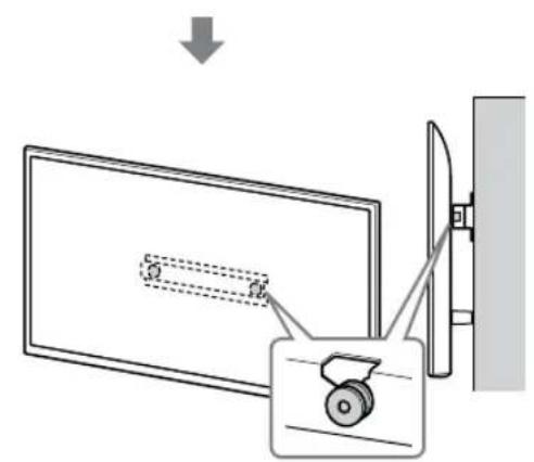
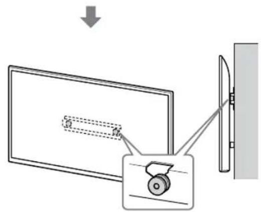
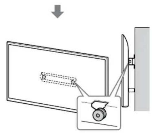
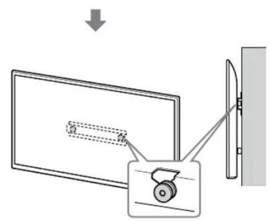
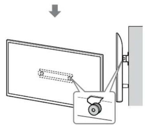
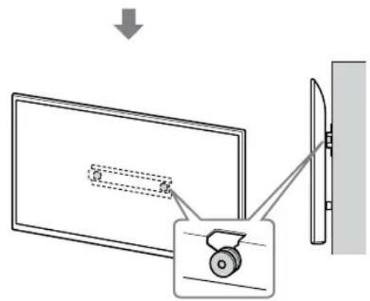
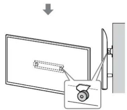
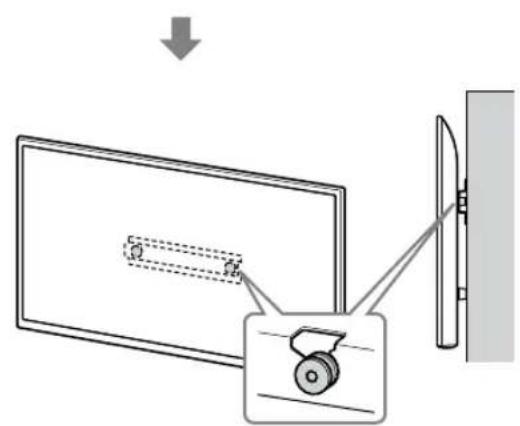
- After installing the TV on the wall, confirm the Pulleys ® are firmly latched into the Base or Base Adaptor.
- Release both hands slowly to ensure that the TV does not fall.
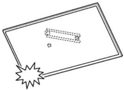
• After installing the TV on the wall, remove the masking tape, etc. from the wall.
![graph TD A["Top Section"] --> B["Downward Correction"] B --> C["Left Side"] C --> D["Right Side"] D --> E["Final Section"]](/content/2026/03/465178/images/f820a29129fb8adf7215cc100a11d5dbde210f64e0d90d809b0f08cba2bc07c3.jpg)
![graph TD A["Step 1: Object Tracking"] --> B["Step 2: Assembly"] B --> C["Step 3: Final Assembly"]](/content/2026/03/465178/images/14948d139ba2170279ea3c31d0f911e8ee517e561a5f7b58776b186f63208107.jpg)
WARNING
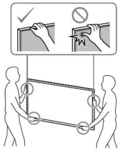
- Be sure that two or more persons (three or more persons for 75 inches and above TV set) hold the TV when carrying it.
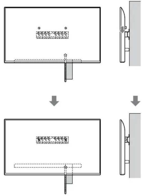
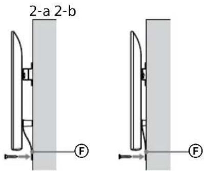
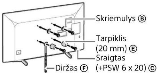
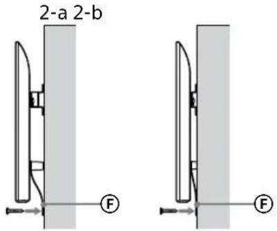
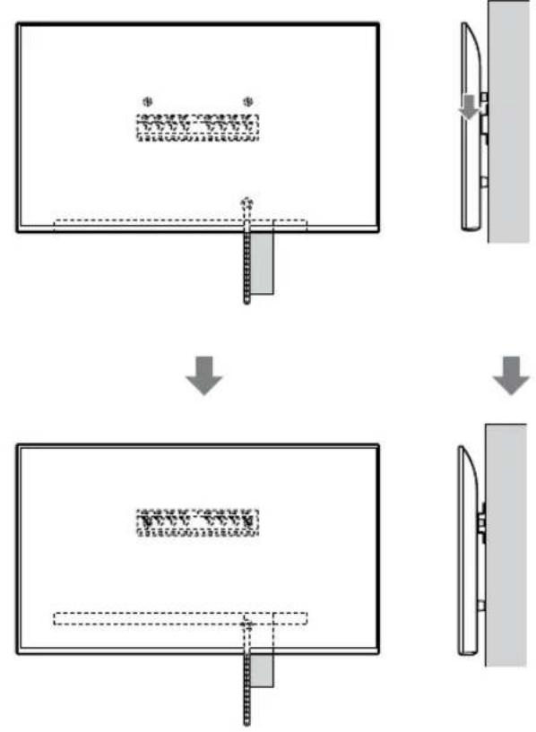
3 Preventing the bottom of the TV from shifting.
- Take up the slack of Belt Ⓔ and attach it to the wall tightly.
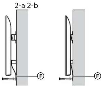
- Use a 5 mm diameter screw or equivalent (not supplied).
Note
- Try to pull the bottom of the TV towards yourself slightly, to make sure that it does not move forward. If there is any movement, it is not fixed correctly, and the Belt ⑤ should be secured firmly again.
KD-65XG81□□ / 65XG80□□ / 55XG81□□ / 55XG80□□ / 49XG81□□ / 49XG80□□ / 43XG81□□ / 43XG80□□
1 Lift the TV.
- For the location of the Pulleys Ⓑ to hang on the Base or Base Adaptor, refer to the table of step 3 in "Deciding on the installation location" on page 7. - Make sure that the rear of the TV touches the Base or Base Adaptor when holding the TV.
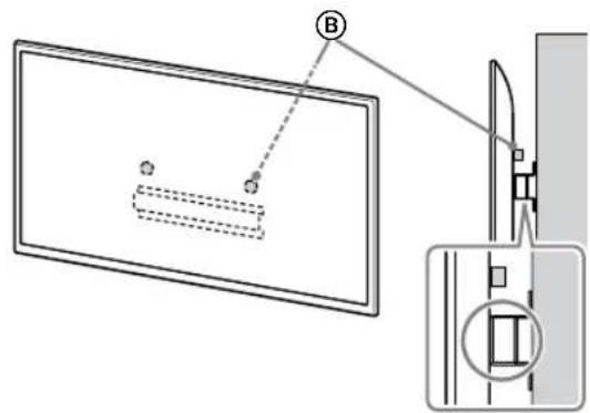
Note
- Hold the TV securely with both hands.
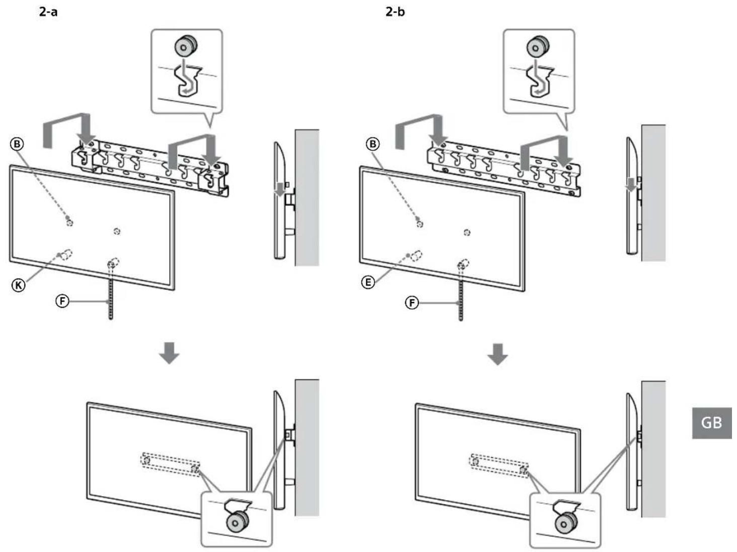
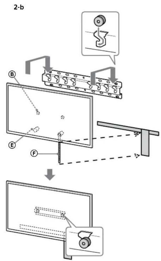
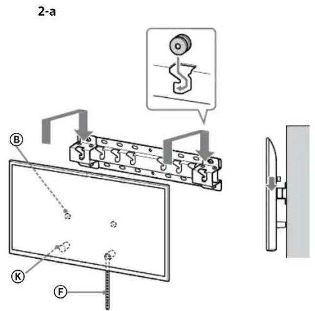
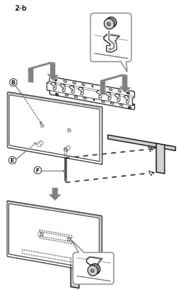
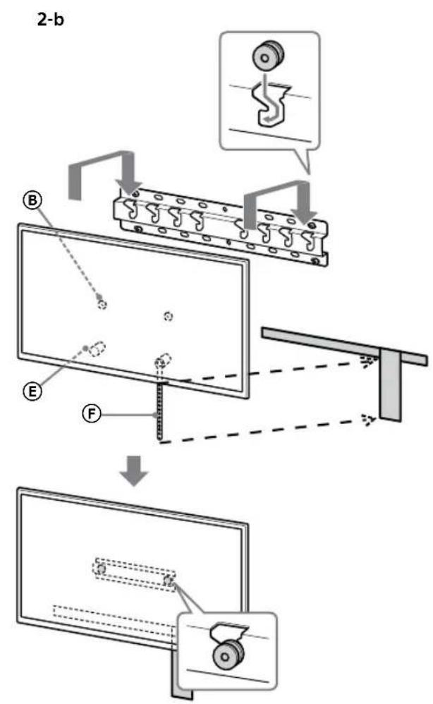
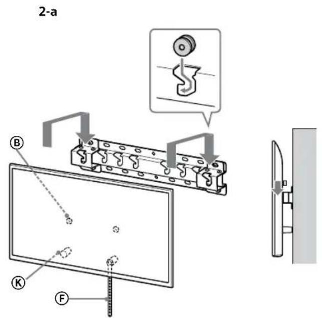
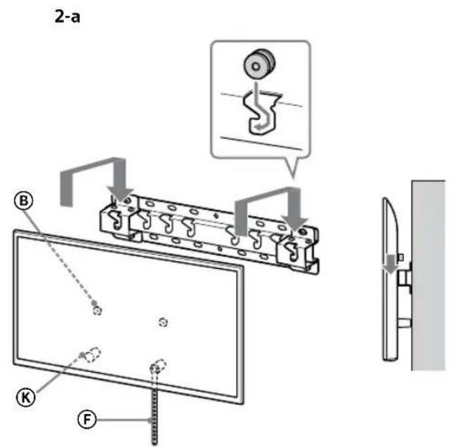
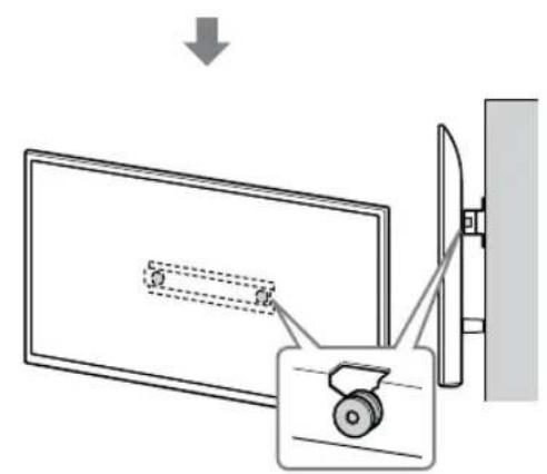
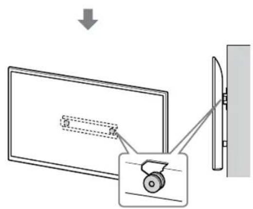
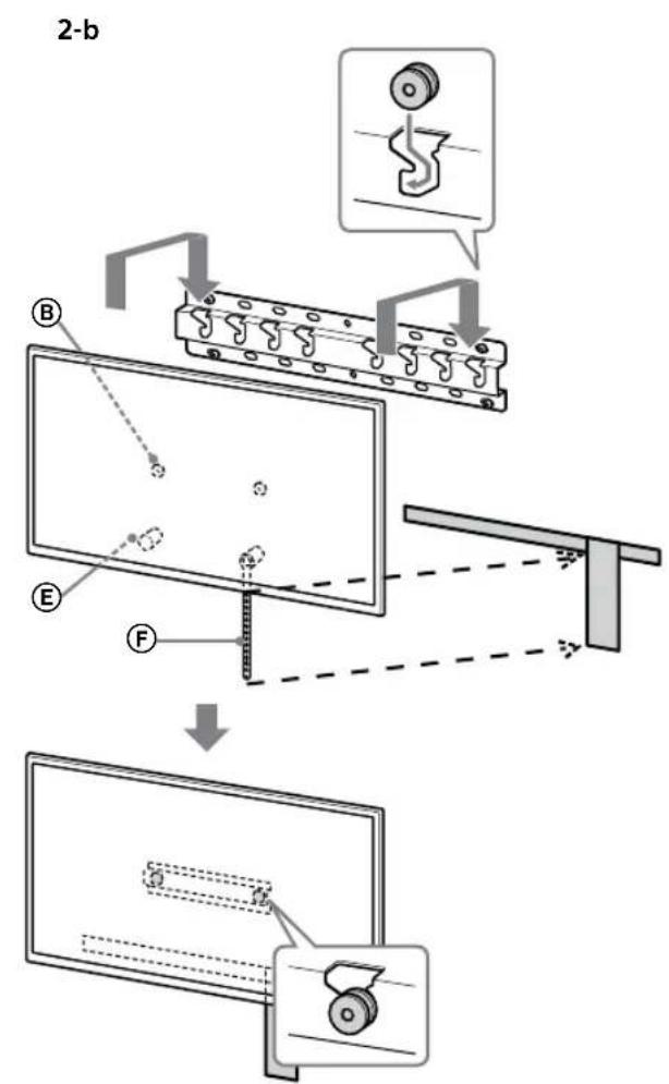
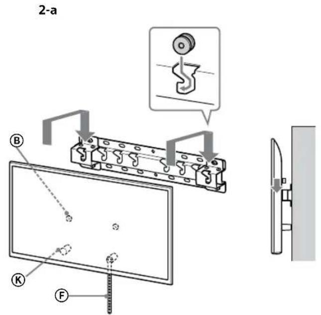
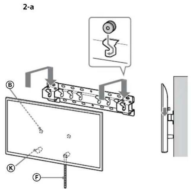
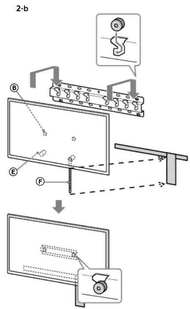
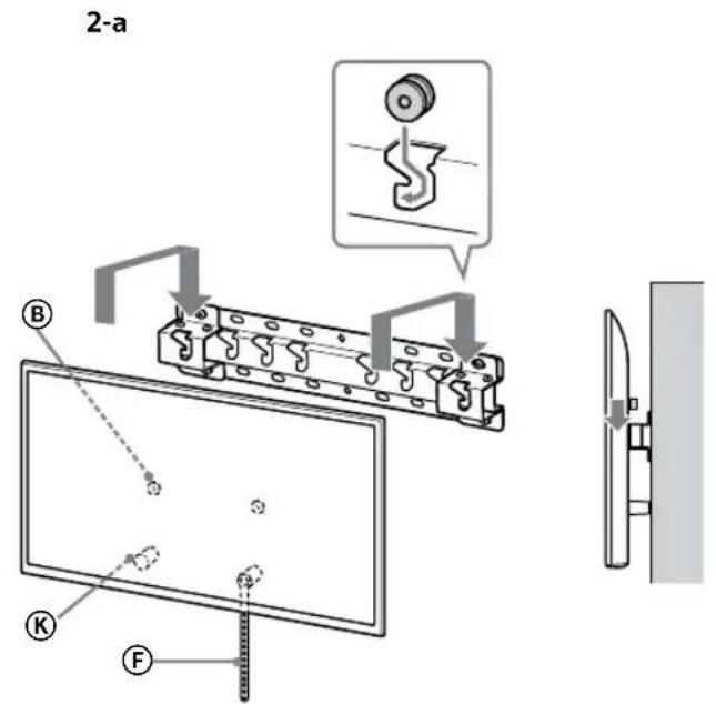
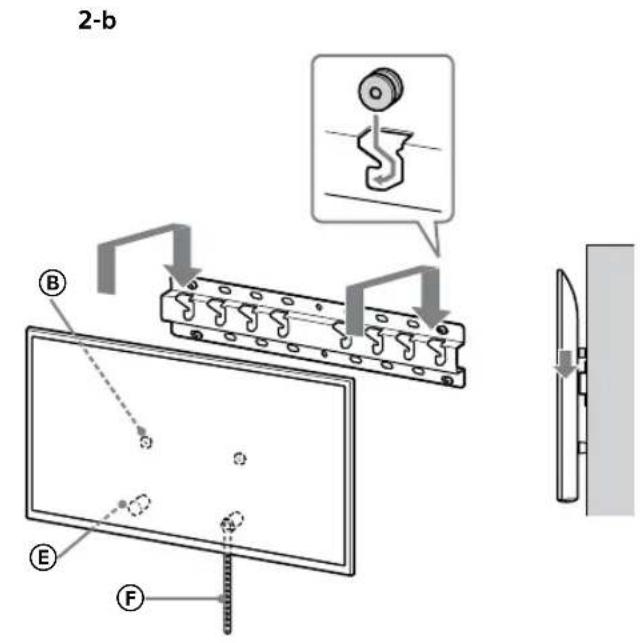
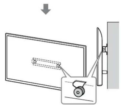
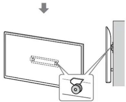
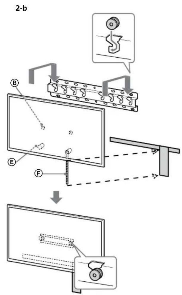
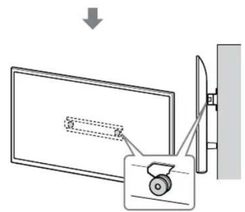
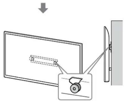
2 Install the TV onto the Base or Base Adaptor.
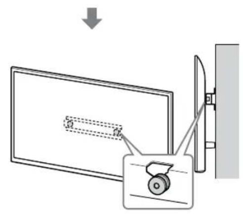
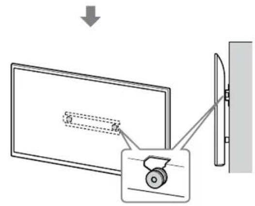
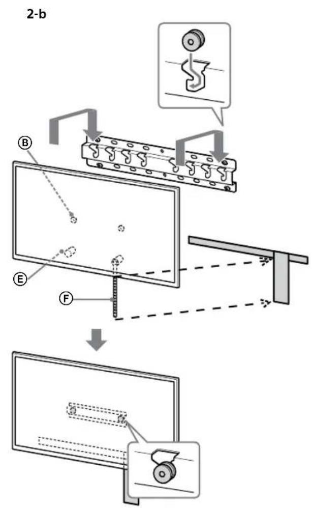
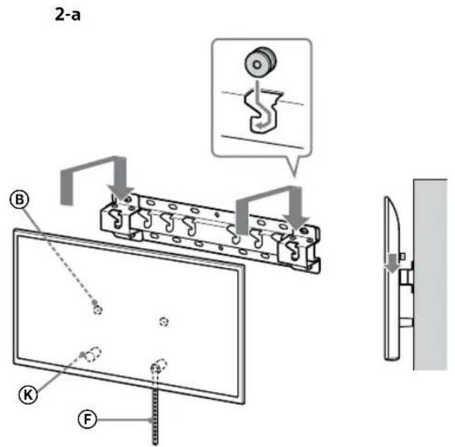
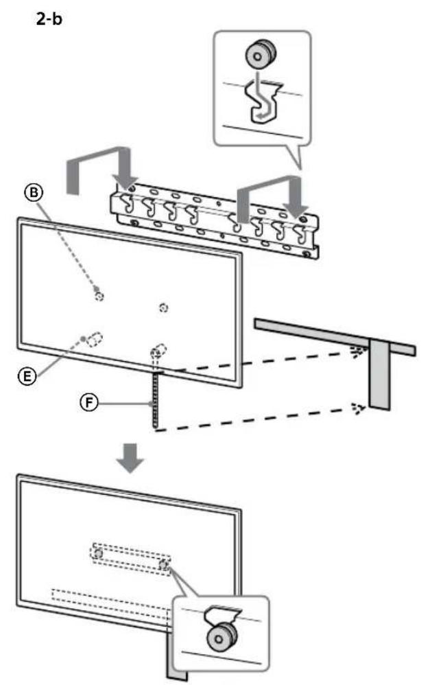
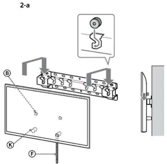
- Gently slide down the TV and hang the Pulleys ⑧ attached to the rear of the TV to the Base or Base Adaptor, making sure to confirm the shape of the holes. - After installing the TV on the wall, confirm the Pulleys ⑧ are firmly latched into the Base or Base Adaptor. - Release both hands slowly to ensure that the TV does not fall.
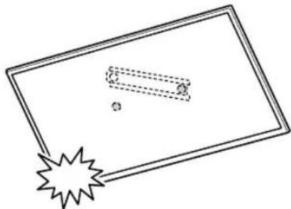
WARNING
- Be sure that two or more persons (three or more persons for 75 inches and above TV set) hold the TV when carrying it.
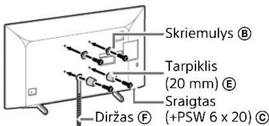
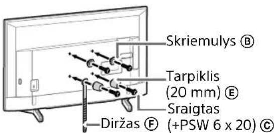
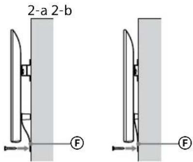
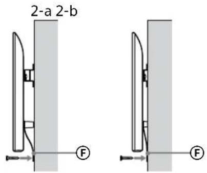
3 Preventing the bottom of the TV from shifting.
- Take up the slack of Belt Ⓔ and attach it to the wall tightly.
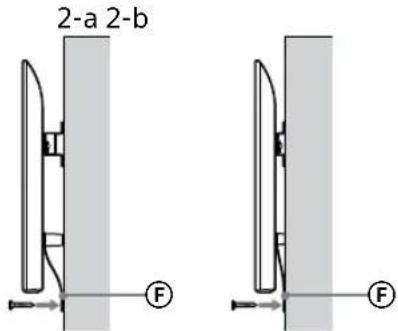
- Use a 5 mm diameter screw or equivalent (not supplied).
Note
- Try to pull the bottom of the TV towards yourself slightly, to make sure that it does not move forward. If there is any movement, it is not fixed correctly, and the Belt ⑤ should be secured firmly again.
Confirming the completion of the installation
Check the following points.
- The Pulleys Ⓑ are firmly hung onto the Base or Base Adaptor.
- The cord and the cable are not twisted or pinched.
- The Belt Ⓕ is tight with no slack.
WARNING
- Improper placement of the mains lead, etc. may cause fire or electric shock through a short circuit. Be sure to confirm the completion of the installation for safety.
Other information
When removing the TV, reverse the previous installation procedure.
WARNING
- Be sure that two or more persons (three or more persons for 75 inches and above TV set) hold the TV when removing it.
Specifications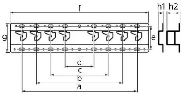
Dimensions: (Approx.) [mm]
a : 400
b: 300
c: 200
d: 100
e: 80
f: 480
g: 100
h1: 20 (case 2-b)
h2: 60 (case 2-a)
Weight (base only): (Approx.) [kg]
0.8
Design and specifications are subject to change without notice.
Note
Note
![graph TD A["Step 1: Object Tracking"] --> B["Step 2: Assembly"] B --> C["Step 3: Final Assembly"]](/content/2026/03/465178/images/f9ea9fb9fad6554c1c3fcb700a9fd4d00da680126feb20ddeda351506aed5de7.jpg)
WARNING
Note
FR
WARNING
WARNING
Dimensions: (approx.) [mm]
a: 400
b: 300
c: 200
d: 100
e: 80
f: 480
g: 100
h1: 20 (case 2-b)
h2: 60 (case 2-a)
Weight (base only): (approx.) [kg]
0.8
Note
Note
![graph TD A["Top View"] --> B["Step 1: Object Tracking & Assembly"] B --> C["Step 2: Breakdown and Reassembly"] C --> D["Final State: Top View with Material Structure"]](/content/2026/03/465178/images/2ffb6fcccc0ed98d946d9cbcf6574a6cf7c44d139e5c41ea1004e27f63379bee.jpg)
WARNING
Note
ES
WARNING
WARNING
Note
Note
![graph TD A["Step 1: Initial material deformation"] --> B["Step 2: Disassembly of material"] B --> C["Step 3: Final assembly with structural break"]](/content/2026/03/465178/images/14ddde5fe2c6630dfaccfd31c311f5983a373c654574f05a2ababd794411bfa4.jpg)
DE
WARNING
Note
DE
WARNING
WARNING
Note
Note
![graph TD A["Step 1: Initial material deformation"] --> B["Step 2: Disassembly of material"] B --> C["Step 3: Final assembly with structural break"]](/content/2026/03/465178/images/9baaecc35488083facbb6a5bc8e3fe9ea24e9d5036267cda3818bea2915ae07e.jpg)
WARNING
Note
NL
WARNING
WARNING
3 Connect the necessary cable(s) to the television.
2 Connect the necessary cable(s) to the television.
2 Connect the necessary cable(s) to the television.
Note
Note
3 Connect the necessary cable(s) to the television.
Note
WARNING
WARNING
Note!
Note!
2 Mount the TV on the base or adapter.
Note!
WARNING
WARNING
Warning
Warning
![graph TD A["Step 1: Object Tracking"] --> B["Step 2: Assembly"] B --> C["Step 3: Final Assembly"]](/content/2026/03/465178/images/3b8b6f245f87fa537aa5cddea39aa72b8720915f95cd2fcc83551bc4f60a6fd2.jpg)
WARNING
Warning
WARNING
WARNING
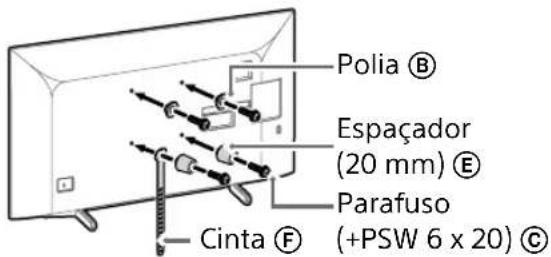
- Repeat the previous step and remove the other side of the TV's Table Stand.
Note
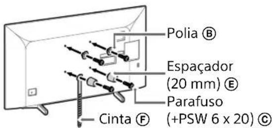
- Repeat the previous step and remove the other side of the TV Table Stand.
Note
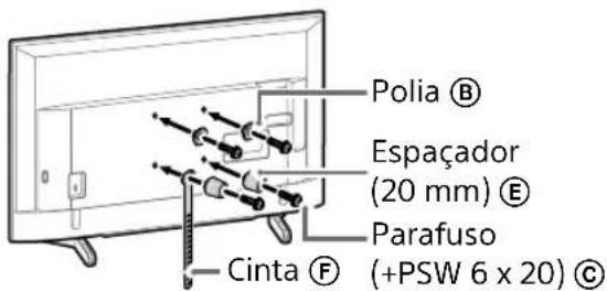
Note
Note
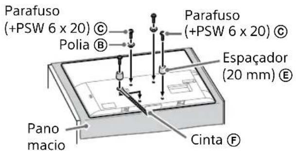
2 Install the TV on the Base or Base Adapter.
- After installing the TV on the wall, remove the painter's tape, etc. from the wall.
![graph TD A["Step 1: Object Tracking"] --> B["Step 2: Assembly"] B --> C["Step 3: Final Assembly"]](/content/2026/03/465178/images/b67a9a4ac67f605ddbfb2a3245015798425435c9f15bf678550173330f890376.jpg)
WARNING
Note
WARNING
WARNING
Weight (base only): (Approx.) [kg]
0.8
Preparation for installation....5
Checking parts 5
Finding a location 6
Preparation for installation
1 Find the location for the TV.
Note
Note
3 How to prevent the TV from moving.
Note
WARNING
3 How to prevent the TV from moving.
WARNING
Note
Note
Note
WARNING
WARNING
2-b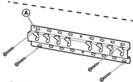
Note
Note
2 Install the TV on the stand or stand adapter.
![graph TD A["Step 1: Object Tracking"] --> B["Step 2: Assembly"] B --> C["Step 3: Final Assembly"]](/content/2026/03/465178/images/f62b93f37398af63879a3fbe502e5c99fa4787df9b9d25256a87329663e5a7f6.jpg)
NO
WARNING
- Make sure that two or more people (three or more people for TVs 75 inches or larger) hold the TV when carrying it.
Note
WARNING
- Make sure that two or more people (three or more people for TVs 75 inches or larger) hold the TV when carrying it.
WARNING
- Make sure that two or more people (three or more people for TVs 75 inches or larger) hold the TV when removing it.
Specifications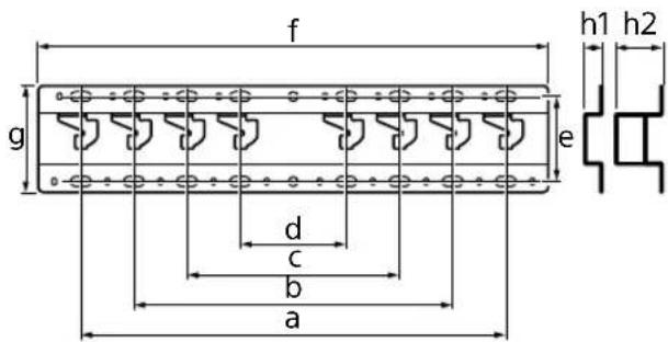
Dimensions: (Approx.) [mm]
a : 400
b : 300
c: 200
d: 100
e: 80
f: 480
g: 100
h1: 20 (case 2-b)
h2: 60 (case 2-a)
Weight (base only): (approx.) [kg]
0.8
Note
Note
![graph TD A["Step 1: Object Tracking"] --> B["Step 2: Assembly"] B --> C["Step 3: Final Assembly"]](/content/2026/03/465178/images/09448484553cbae4a98fc4144a77bb86ddc872621465024967f58f83aaa06a7b.jpg)
WARNING
Note
WARNING
WARNING
Not
Not
![graph TD A["Step 1: Object Tracking"] --> B["Step 2: Assembly"] B --> C["Step 3: Final Assembly"]](/content/2026/03/465178/images/2a61ab8bffc679c232bc6965dcfbf2f12ab5ba11beff5f3fa7be399d8048e163.jpg)
WARNING
Not
WARNING
WARNING
Note
Note
Note
![graph TD A["Step 1: Object Tracking"] --> B["Step 2: Assembly"] B --> C["Step 3: Final Assembly"]](/content/2026/03/465178/images/40fba88dabc73cad334af86723c150a31a72c57937c38db51a465d5718db5dc3.jpg)
WARNING
Note
WARNING
WARNING
Note
Note
Note
WARNING
WARNING
4 Determine the position of the screws for mounting the base (20) Ⓐ.
Note
Note
3 Connect the necessary cables to the TV receiver.
![graph TD A["Top View"] --> B["Step 1: Top View with a textured rectangular block and a small rectangular component"] B --> C["Step 2: Top View with a flat rectangular block and a small rectangular component"] C --> D["Step 3: Top View with a flat rectangular block and a small rectangular component"]](/content/2026/03/465178/images/a13aec60aa106b2817cc5157080193b27d0ac1d31834fdb5fa02b12befed4c41.jpg)
CAUTION
Note
SK
WARNING
WARNING
Dimensions: (approx.) [mm]
a: 400
b: 300
c: 200
d: 100
e: 80
f: 480
g: 100
Note
Note
![graph TD A["Top View"] --> B["Step 1: Inserted Component"] B --> C["Step 2: Assembly/Adjustment"] C --> D["Step 3: Final Assembly"]](/content/2026/03/465178/images/f8d0dcbaed4314e4cac7e1092d39226615b6b693b0c51d20b222f60bd05d8a15.jpg)
WARNING
Note
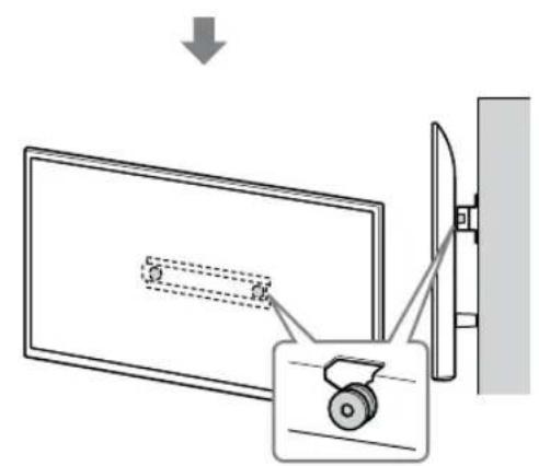
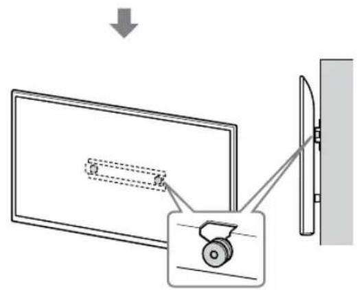
RO
WARNING
WARNING
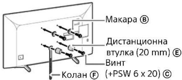
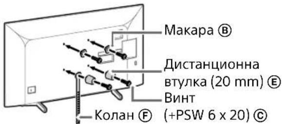
Note
Note
![graph TD A["Top View"] --> B["Step 1: Inserted Component"] B --> C["Step 2: Assembly/Adjustment"] C --> D["Step 3: Final Assembly"]](/content/2026/03/465178/images/17db18e2cca19e9be75947b797ba1461f2f3c3f3db584d80dbf3b109d538e148.jpg)
BG
WARNING
Note
BG
WARNING
3 Prevention
WARNING
Note
Note
![graph TD A["Step 1: Object Tracking"] --> B["Step 2: Assembly"] B --> C["Step 3: Final Assembly"]](/content/2026/03/465178/images/b44c99bb83cca7970d4f105db363d3aa492e8dbc123879ddc9a98150010d2087.jpg)
WARNING
Note
WARNING
WARNING
Note
Note
![graph TD A["Top View"] --> B["Downward Correction"] B --> C["Left Side"] C --> D["Right Side"]](/content/2026/03/465178/images/6e9508b1bff78d4179823fcebc4ce6e76ca4d0fe88c4015d87ac3225f0c23e94.jpg)
WARNING
Note
UA
WARNING
WARNING
Note.
Note.
- After installing the TV on the wall, remove the tape or similar from the wall.
![graph TD A["Initial State"] --> B["Step 1: Initial State with a rectangular block and dimension annotation"] B --> C["Step 2: Step 1: Initial State with a dashed line and dimension annotation"] C --> D["Step 3: Step 2: Initial State with a dashed line and dimension annotation"]](/content/2026/03/465178/images/8dea47b0e6ee2fe444432e267dc687309de10860b69943db780271965bebeef8.jpg)
![graph TD A["Step 1: Object Tracking"] --> B["Step 2: Assembly"] B --> C["Step 3: Final Assembly"]](/content/2026/03/465178/images/2b2ac94e3284d10881d5dd6a9b3d478193cda77d897258878275b1be2c7e0063.jpg)
WARNING
Note.
- Hold the TV securely with both hands.
WARNING
WARNING
Mass (stand only): (approx.) [kg]
0.8
Connect the necessary cable(s) to the TV.
Connect the required cable(s) to the TV.
Note
Note
2 Install the TV on the base or base adapter.
![graph TD A["Step 1: Object Tracking"] --> B["Step 2: Assembly"] B --> C["Step 3: Final Assembly"]](/content/2026/03/465178/images/8b33f059a634ca14639d568dde0bb805d56e59d6f272240c0a03ac7b504920a0.jpg)
WARNING!
3 Do not tilt the bottom of the TV.
- Grasp the end of the strap Ⓕ and firmly attach it to the wall.
Note
- Hold the TV firmly with both hands.
2 Install the TV on the base or base adapter.

WARNING!
3 Do not tilt the bottom of the TV.
- Grasp the end of the strap Ⓖ and firmly attach it to the wall.
WARNING!
Note
Note
![graph TD A["Step 1: Object Tracking"] --> B["Step 2: Assembly"] B --> C["Step 3: Final Assembly"]](/content/2026/03/465178/images/0017876afa3a4405ff68c1bb66f224d0fa5e7677ef6d30e7664c32b5bf8bc7c4.jpg)
WARNING
Note
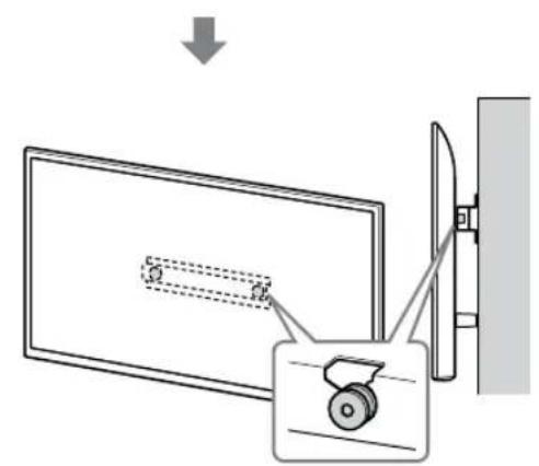
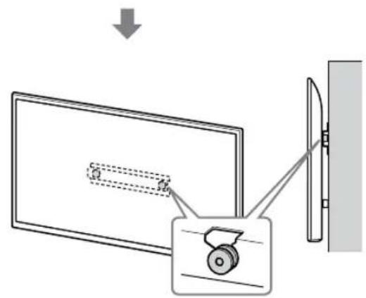
WARNING
WARNING
4 Determine the positions of the screws for mounting the stand (20) Ⓐ.
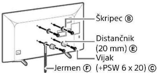
3 Connect the necessary cables to the TV.
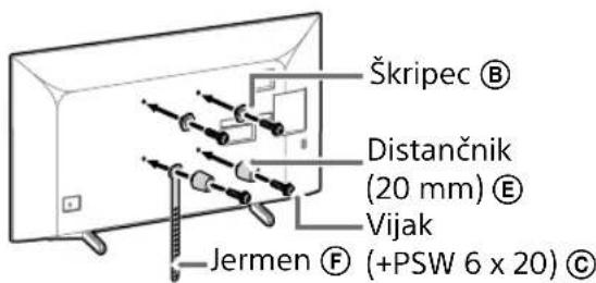
2 Connect the necessary cables to the TV.
Before mounting the TV on the wall, be sure to connect the cables. Once the TV is mounted, you will not be able to connect the cables.
2 Connect the necessary cables to the TV.
Before mounting the TV on the wall, be sure to connect the cables. Once the TV is mounted, you will not be able to connect the cables.
Note
Note
3 Connect the necessary cables to the TV.
2 Mount the TV on the stand or the stand adapter.
- After installing the TV on the wall, remove the masking tape, etc. from the wall.
![graph TD A["Initial State"] --> B["Step 1: Initial State with a rectangular block and dimension annotation"] B --> C["Step 2: Transformation to a vertical panel with a curved arrow indicating the process"] C --> D["Step 3: Final State with a rectangular block and dimension annotation"]](/content/2026/03/465178/images/8f415c110c4db0862f7e3b8ecdbda46ba0ef36d911e9bfbf5a7628703a6b89a7.jpg)
![graph TD A["Step 1: Object Tracking"] --> B["Step 2: Assembly"] B --> C["Step 3: Final Assembly"]](/content/2026/03/465178/images/c77f3cfc31a370fdb4f78b398fa62af41725dc53728a07f395520a011f7a236e.jpg)
WARNING
Note
- Hold the TV firmly with both hands.
2 Install the TV on the stand or stand adapter.
- Carefully lower the TV and hang the brackets Ⓑ attached to the back of the TV on the stand or stand adapter, while making sure to check the shape of the holes. - After installing the TV on the wall, confirm that the brackets Ⓑ are securely hooked onto the stand or stand adapter. - Slowly release both hands to ensure the TV does not fall.
WARNING
WARNING
4 Decide on the position of the screw for setting up the base (20) Ⓐ.
Refer to the specification on page 19. When you select option 2-a, use the base adapter hole positions ①.
WARNING
- The wall on which you install the TV must support at least four times the weight of the TV (Refer to your TV's Reference Guide for its weight).
- Check the strength of the wall on which you will install the TV. If necessary, reinforce the wall.
Installing the base on the wall
- Prepare four or more screws with a diameter of 8 mm or similar screws (not supplied).
- Attach the four screws into the holes for the adapter base ① In the case of the base (20) ④ (only for 2-a). • Place the base (20) Ⓐ on the wall horizontally.
Preparation for mounting the TV on the wall
For setting up the stand, refer to the Setup Guide.
KD-75XG80□□
3 Connect the necessary cables to the TV.
Be sure to connect the cables before mounting the TV on the wall. You will not be able to connect the cables once the TV is mounted. Refer to the Reference Guide supplied with your TV.
Note
- Repeat the previous step and remove the other side of the table-top stand.
Note
2 Connect the necessary cables to the TV.
Be sure to connect the cables before mounting the TV on the wall. You will not be able to connect the cables once the TV is mounted. Refer to the Reference Guide supplied with your TV.
Note
- Have a licensed contractor run the cables through the wall.
- Connect the connection cables so that you do not step on them before mounting the unit on the wall.
3 Remove the Table-Top Stand from the TV.
- Remove the table-top stand one side at a time. Firmly hold the table-top stand with both hands while another person lifts the TV.
- Repeat the previous step and remove the other side of the table-top stand.
Note
2 Connect the necessary cables to the TV.
Be sure to connect the cables before mounting the TV on the wall. You will not be able to connect the cables once the TV is mounted. Refer to the Reference Guide supplied with your TV.
Note
- Have a licensed contractor run the cables through the wall.
- Connect the connection cables so that you do not step on them before mounting the device on the wall.
3 Remove the Table-Top Stand from the TV.
Note
Note
- Be careful to place the TV on a soft cloth to prevent damage to the screen surface.
- When installing the Wall-Mount Bracket, do not use the screws that you removed from the Table-Top Stand.
- Be sure to store the removed Table-Top Stand and its screws in a safe place, keeping them away from children. You will need them if you want to keep the TV on a table in the future. The Table-Top Stand cannot be purchased separately.
WARNING
3 Connect the necessary cables to the television.
Be sure to connect the cables before mounting the television on the wall. You will not be able to connect the cables once the television is mounted. Refer to the Reference Guide supplied with your TV.
Note
2 Place the TV on the base or base adapter.
- After installing the TV on the wall, remove the adhesive tape from the wall.
![graph TD A["Initial State"] --> B["Step 1: Initial State with a rectangular block and dimension annotation"] B --> C["Step 2: Transformation to a vertical panel with a curved arrow indicating the process"] C --> D["Step 3: Final State with a rectangular block and dimension annotation"]](/content/2026/03/465178/images/adc4d8b89347345fb4309d49a15bea81a48daf7765ba5926c028825037cd013f.jpg)
![graph TD A["Step 1: Object Tracking"] --> B["Step 2: Assembly"] B --> C["Step 3: Final Assembly"]](/content/2026/03/465178/images/8359924708bae31b4781effb0e24610ea7a2e9d5ec74c56cd059e2393bb58d75.jpg)
WARNING
3 Preventing the TV from tipping over.
- Take a piece of strap Ⓔ and lightly attach it to the wall.
Note
- Hold the TV firmly with both hands.
2 Place the TV on the base or base adapter.
WARNING
3 Preventing the TV from tipping over.
- Take a piece of strap Ⓔ and lightly attach it to the wall.
WARNING
- Make sure that two or more people (three or more people for a TV 75 inches or larger) hold the TV when removing it.
Specifications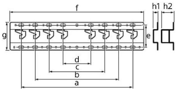
Dimensions: (approximately) [mm]
a : 400
b : 300
c : 200
d : 100
e : 80
f : 480
g : 100
4 Determine the position of the screws for the mounting holes (20) Ⓐ.
Instruction
Instruction
CAUTION
Instruction
4 Decide the positions of the screws for mounting the base (20) Ⓐ.
See specifications on page 19. When selecting 2-a, choose the positions of the adapter bracket holes ①.
WARNING
- The wall on which the TV will be mounted should be able to support a weight of at least four times the weight of the TV (See your TV's Reference Guide for its weight).
- Determine the strength of the wall on which the TV will be mounted. Reinforce the wall sufficiently, if necessary.
Mounting the base on the wall
- Use four or more screws of 8 mm diameter or equivalent (not supplied).
- Place four screws into the base bracket holes ① with the base (20) Ⓐ (only 2-a).
- Place the base (20) Ⓐ horizontally on the wall.
Preparation for mounting the TV
See the Setup Guide for mounting the stand.
KD-75XG80□□
1 Mark the mounting location on the wall.
- Repeat the previous step and remove the other side of the table-top stand.
Note
- Three or more people are required to detach the table-top stand.
- Be careful not to use excessive force when detaching the table-top stand from the TV, as this may cause the TV to fall and result in personal injury or physical damage to the TV.
- Handle the table-top stand carefully to avoid damaging the TV.
- Carefully lift the TV while detaching the table-top stand to prevent it from tipping over and causing injury.
- Carefully detach the table-top stand from the TV to prevent it from falling and damaging the surface on which the TV is placed.
KD-65XG81□□ / 65XG80□□
1 Attach the attachment parts for the wall-mount bracket. Check the attachment parts by referring to "Supplied with SU-WL450" in "Checking the Parts" on page 5.
Note
- Repeat the previous step and remove the other side of the table-top stand.
Note
- Three or more people are required to detach the table-top stand.
- Be careful not to use excessive force when detaching the table-top stand from the TV, as this may cause the TV to fall and result in personal injury or physical damage to the TV.
- Handle the table-top stand carefully to avoid damaging the TV.
- Carefully lift the TV while separating the table-top stand to prevent it from tipping over and causing injury.
- Carefully detach the table-top stand from the TV to prevent it from falling and damaging the surface on which the TV is placed.
KD-55XG81□□ / 55XG80□□
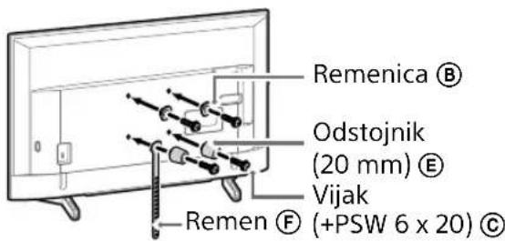
1 Attach the attachment parts to the wall-mount bracket. Check the attachment parts by referring to "Supplied with SU-WL450" in "Checking the parts" on page 5.
Note
Note
- Carefully lift the TV while separating the table-top stand to prevent it from tipping over and causing injury.
- Carefully detach the table-top stand from the TV to prevent it from falling and damaging the surface on which the TV is placed.
KD-49XG81□□ / 49XG80□□ / 43XG81□□ / 43XG80□□
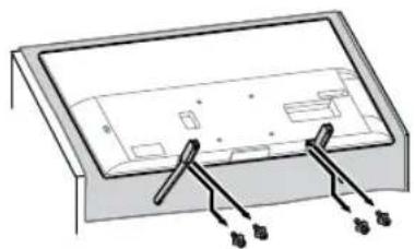
1 Detach the table-top stand from the TV.
Note
- Make sure to place the TV on a soft cloth to prevent damage to the screen surface.
- When installing the wall-mount bracket, do not use the screws removed from the table-top stand.
- Be sure to store the removed table-top stand and its screws in a safe place, keeping them away from children. You will need them if you wish to use the TV on a table in the future. The table-top stand cannot be purchased separately.
WARNING
- Make sure the TV is in the vertical position before turning it on. The TV must not be turned on with the LCD panel facing down to avoid uneven picture uniformity.
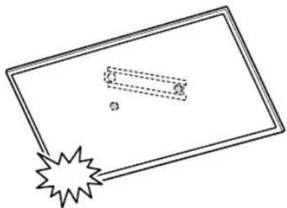
- If pressure or impact is applied to the surface of the TV, the TV may break or be damaged.
- Place the TV face down on a stable and flat surface with the table-top stand hanging over the edge of the surface. Holding the face of the TV and the base of the table-top stand on the same flat surface will create unstable working conditions and may damage the TV.
- When detaching the table-top stand from the TV, hold the table-top stand firmly with both hands.
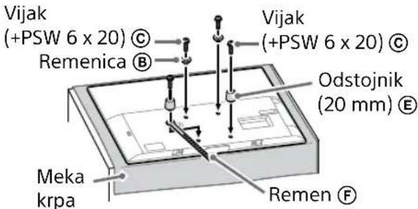
2 Attach the attachment parts to the wall-mount bracket. Check the attachment parts by referring to "Supplied with SU-WL450" in "Checking the parts" on page 5.
Note
2 Place the TV on the base or base connector.
- Carefully move the TV and hang the belts ⑧ on the rear of the TV onto the base or base connector, making sure they match the shape of the openings.
- After mounting the TV on the wall, check that the belts Ⓑ are firmly attached to the base or base connector.
- Slowly release both hands so that the TV does not fall.
- When installing the TV on the wall, remove the crepe tape from the wall.
![graph TD A["Initial State"] --> B["Step 1: Initial State with a rectangular block and dimension annotation"] B --> C["Step 2: Transformation to a vertical panel with a curved arrow indicating the process"] C --> D["Step 3: Final State with a rectangular block and dimension annotation"]](/content/2026/03/465178/images/afc411d630d22d1c79e5b072d2e47a2ac3bba123098971a99796c4c6781b602a.jpg)
![graph TD A["Step 1: Object Tracking"] --> B["Step 2: Assembly"] B --> C["Step 3: Final Assembly"]](/content/2026/03/465178/images/80738dea95d1d326c63d2be1cfefbf7e581322e6aacb7a6b9d9a80f71fb7e71a.jpg)
WARNING
3 Preventing the bottom of the TV from moving.
- Lift the loose part of the belt Ⓔ and attach it firmly to the wall.
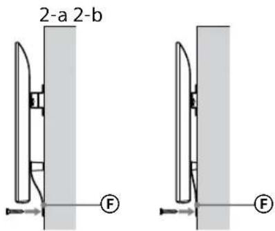
- Use a screw with a diameter of 5 mm or equivalent (not supplied).
Note
Note
WARNING
3 Preventing the TV from moving.
- Lift the loose part of the strap Ⓔ and attach it firmly to the wall.
- Use a screw with a diameter of 5 mm or equivalent (not supplied).
Note
WARNING
תְרָה
תְקָרִי אַלְאָה
3
.תְקָרִיַעֹ
• אַרָאִי אַרָאִי (
.הכלה
. כְרָה אַרִי לְקֹת


- TO CUSTOMERS
- TO SONY DEALERS AND CONTRACTORS
- ON SAFETY
- TO SONY DEALERS
- CAUTION
- SPECIFIED PRODUCTS
- WARNING
- BE SURE TO SUBCONTRACT THE INSTALLATION TO LICENSED CONTRACTORS AND KEEP SMALL CHILDREN AWAY DURING THE INSTALLATION
- BE SURE TO SUBCONTRACT MOVING OR DISMOUNTING OF THE TV TO LICENSED CONTRACTORS
- DO NOT REMOVE SCREWS, ETC., AFTER MOUNTING THE TV
- DO NOT MAKE ALTERATIONS TO THE PARTS OF THE WALL-MOUNT BRACKET
- DO NOT MOUNT ANY EQUIPMENT OTHER THAN THE SPECIFIED PRODUCT
- DO NOT APPLY ANY LOAD OTHER THAN THE TV ON THE WALL-MOUNT BRACKET. DO NOT SHAKE THE TV LEFT/RIGHT, UP/DOWN
- DO NOT LEAN ON OR HANG FROM THE TV
- DO NOT HANDLE THE PRODUCT WITH EXCESSIVE FORCE DURING CLEANING OR MAINTENANCE
- PRECAUTIONS
- INSTALLING THE WALL-MOUNT BRACKET
- DO NOT INSTALL THE WALL-MOUNT BRACKET ON WALL SURFACES WHERE THE CORNERS OR SIDES OF THE TV PROTRUDE AWAY FROM THE WALL SURFACE
- DO NOT INSTALL THE TV OVER OR UNDER AN AIR CONDITIONER
- BE SURE TO INSTALL THE WALL-MOUNT BRACKET SECURELY TO THE WALL FOLLOWING THE INSTRUCTIONS IN THIS INSTRUCTION MANUAL
- BE SURE TO ASSEMBLE THE BRACKET PROPERLY FOLLOWING THE INSTRUCTED PROCEDURE EXPLAINED IN THIS INSTRUCTION MANUAL
- BE SURE TO TIGHTEN THE SCREWS SECURELY IN THE DESIGNATED POSITION
- BE CAREFUL NOT TO SUBJECT THE TV TO SHOCK DURING INSTALLATION
- BE SURE TO INSTALL THE TV ON A WALL THAT IS BOTH PERPENDICULAR AND FLAT
- AFTER PROPER INSTALLATION OF THE TV, SECURE THE CABLES PROPERLY
- DO NOT ALLOW THE MAINS LEAD OR THE CONNECTING CABLE TO BE PINCHED
- THE SCREWS NEEDED TO SECURE THE WALL-MOUNT BRACKET TO THE WALL ARE NOT SUPPLIED
- TABLE OF CONTENTS
- INSTALLING THE TV ONTO THE WALL
- NOTE
- PREPARING FOR INSTALLATION
- CHECKING THE PARTS
- SUPPLIED WITH SU-WL
- DECIDING ON THE INSTALLATION LOCATION
- DECIDE ON THE INSTALLATION LOCATION
- INSTALLING THE BASE ON THE WALL
- PREPARING FOR THE INSTALLATION OF THE TV
- KD-75XG
- MARK THE INSTALLATION LOCATION ON THE WALL
- ATTACH THE ATTACHMENT PARTS FOR WALL-MOUNT BRACKET. CHECK THE ATTACHMENT PARTS BY REFERRING TO "SUPPLIED WITH SU-WL450" IN "CHECKING THE PARTS" ON PAGE
- SLIM MOUNTING (2-B)
- CONNECT THE NECESSARY CABLE(S) TO THE TV
- DETACH THE TABLE-TOP STAND FROM THE TV
- KD-65XG81□□ / 65XG
- KD-55XG
- XG
- ATTACH THE ATTACHMENT PARTS FOR THE WALL-MOUNT BRACKET. CHECK THE ATTACHMENT PARTS BY REFERRING TO "SUPPLIED WITH SU-WL450" IN "CHECKING THE PARTS" ON PAGE
- INSTALLING THE TV ON THE WALL
- LIFT THE TV
- INSTALL THE TV ONTO THE BASE OR BASE ADAPTOR
- PREVENTING THE BOTTOM OF THE TV FROM SHIFTING
- CONFIRMING THE COMPLETION OF THE INSTALLATION
- OTHER INFORMATION
- CONNECT THE NECESSARY CABLE(S) TO THE TELEVISION
- MOUNT THE TV ON THE BASE OR ADAPTER
- INSTALL THE TV ON THE BASE OR BASE ADAPTER
- WEIGHT (BASE ONLY): (APPROX.) [KG]
- PREPARATION FOR INSTALLATION
- FIND THE LOCATION FOR THE TV
- HOW TO PREVENT THE TV FROM MOVING
- INSTALL THE TV ON THE STAND OR STAND ADAPTER
- NOT
- DETERMINE THE POSITION OF THE SCREWS FOR MOUNTING THE BASE (20) Ⓐ
- CONNECT THE NECESSARY CABLES TO THE TV RECEIVER
- PREVENTION
- MASS (STAND ONLY): (APPROX.) [KG]
- CONNECT THE REQUIRED CABLE(S) TO THE TV
- DO NOT TILT THE BOTTOM OF THE TV
- DETERMINE THE POSITIONS OF THE SCREWS FOR MOUNTING THE STAND (20) Ⓐ
- CONNECT THE NECESSARY CABLES TO THE TV
- MOUNT THE TV ON THE STAND OR THE STAND ADAPTER
- DECIDE ON THE POSITION OF THE SCREW FOR SETTING UP THE BASE (20) Ⓐ
- PREPARATION FOR MOUNTING THE TV ON THE WALL
- REMOVE THE TABLE-TOP STAND FROM THE TV
- CONNECT THE NECESSARY CABLES TO THE TELEVISION
- PLACE THE TV ON THE BASE OR BASE ADAPTER
- PREVENTING THE TV FROM TIPPING OVER
- DIMENSIONS: (APPROXIMATELY) [MM]
- INSTRUCTION
- DECIDE THE POSITIONS OF THE SCREWS FOR MOUNTING THE BASE (20) Ⓐ
- MOUNTING THE BASE ON THE WALL
- PREPARATION FOR MOUNTING THE TV
- MARK THE MOUNTING LOCATION ON THE WALL
- KD-55XG81□□ / 55XG
- ATTACH THE ATTACHMENT PARTS TO THE WALL-MOUNT BRACKET. CHECK THE ATTACHMENT PARTS BY REFERRING TO "SUPPLIED WITH SU-WL450" IN "CHECKING THE PARTS" ON PAGE
- PLACE THE TV ON THE BASE OR BASE CONNECTOR
- PREVENTING THE BOTTOM OF THE TV FROM MOVING
- PREVENTING THE TV FROM MOVING
- כְרָה אַרִי לְקֹת
Brand : SONY
Model : Bravia KD49XG8196
Category : Television