
V12H777020 - Projector Accessory EPSON - Free user manual and instructions
Find the device manual for free V12H777020 EPSON in PDF.
| Product type | Projector wall mount |
| Brand | Epson |
| Model | V12H777020 |
| Total weight of mount (assembled) | Approx. 8.4 kg (18.5 lb) |
| Maximum load capacity | 7 kg (15.4 lb) |
| Vertical slide adjustment range | ±38 mm (±1.5 in) |
| Horizontal slide adjustment range | ±45 mm (±1.8 in) |
| Forward/backward slide adjustment range | 0 to 360 mm (0 to 14.2 in) |
| Horizontal roll adjustment range | ±3° |
| Horizontal rotation adjustment range | ±8° |
| Vertical tilt adjustment range | ±3° |
| Weight of touch unit | Approx. 450 g (16 oz) |
| Weight of control box | Approx. 240 g (8.5 oz) |
| Wall mounting type | 3-piece wall plate, M10 bolts (not included) |
| Compatibility | Projectors BrightLink 475Wi/480i/485Wi/575Wi/585Wi/595Wi, BrightLink Pro 1410Wi/1420Wi/1430Wi, PowerLite 470/475W/480/485W/570/575W/580/585W |
| Laser class of touch unit | Class 1 (compliant with JIS C 6802:2011) |
| Installation | By at least two qualified technicians, on a concrete wall |
| Material | Steel |
| Package contents | Mounting bracket, wall plate, 3-axis adjustment device, sliding plate, screws, keys, etc. |
| Maintenance | Regular inspection of screws and bolts, do not use adhesives or lubricants |
Frequently Asked Questions - V12H777020 EPSON
User questions about V12H777020 EPSON
0 question about this device. Answer the ones you know or ask your own.
Ask a new question about this device
Download the instructions for your Projector Accessory in PDF format for free! Find your manual V12H777020 - EPSON and take your electronic device back in hand. On this page are published all the documents necessary for the use of your device. V12H777020 by EPSON.
USER MANUAL V12H777020 EPSON
This guide describes how to mount the ultra-short-throw projectors listed below to a wall using the included Epson® wall mount. It also explains how to install the Control Pad and Touch Unit after wall mount installation.
The following projectors are covered by this guide:
- BrightLink® 475Wi/480i/485Wi/575Wi/585Wi/595Wi and 575Wi+/585Wi+/595Wi+
- BrightLink Pro 1410Wi/1420Wi/1430Wi
- PowerLite ^ 470/475W/480/485W/570/575W/580/585W
Safety Instructions
For your safety, read all the instructions in this guide before using the wall mount. Incorrect handling that ignores instructions in this guide could damage the wall mount or could result in personal injury or property damage. Keep this installation guide on hand for future reference.
Read the safety instructions in the User's Guide for your projector and follow the instructions in this document.
Explanation of Symbols
The warning marks shown below are used throughout this installation guide to prevent personal injury or property damage. Make sure you understand these warnings when reading this installation guide.
| Warning | This symbol indicates information that, if ignored, could possibly result in personal injury or even death due to incorrect handling. |
| Caution | This symbol indicates information that, if ignored, could possibly result in personal injury or physical damage due to incorrect handling. |
| This symbol indicates related or useful information. | |
| Symbol indicating an action that must not be done | |
| Symbol indicating an action that should be done | |
Safety Precautions for Installation
| Warning | |
| The wall mount is designed specifically for mounting a projector to a wall. If anything other than a projector is mounted, the weight may result in damage. If the wall mount falls, it could cause personal injury or property damage. | |
| The installation work (wall mounting) should be performed by specialists who have technical knowledge and ability. Incomplete or incorrect installation could cause the wall mount to fall and cause personal injury or property damage. | |
| Follow the instructions in this guide when installing the wall mount. If the instructions are not followed, the wall mount may fall, resulting in personal injury or property damage. | |
| Follow the instructions in this guide to install and operate the Touch Unit. If the Touch Unit is not installed and operated properly, the light emitted from the laser could cause injury to eyesight. | |
| Warning | |
| Handle the power cord carefully. Incorrect handling may cause fire or electric shock. Observe the following precautions when handling: Do not handle the power plug with wet hands. Do not use a power cord that is damaged or modified. Do not pull the power cord with too much force when routing the cable through the wall mount. | |
| Do not install the wall mount in a place where it might be subjected to vibration or shock. Vibration or shock could cause damage to the projector or mounting surface. It could also cause the wall mount or projector to fall and cause personal injury or property damage. | |
| The installation work should be performed by at least two qualified service personnel. If you need to loosen any screws during installation, be careful not to drop the wall mount. If the wall mount or projector falls, it could cause personal injury or property damage. | |
| Install the wall mount so that it can sufficiently support the weight of the projector and wall mount, and resist any horizontal vibration. Use M10 nuts and bolts and make sure to use appropriate wall anchors for your wall type. Nuts and bolts smaller than M10 could cause the wall mount to fall. Epson accepts no responsibility for any damage or injury caused by lack of wall strength or inadequate installation. | |
| When you mount the projector on the wall with the wall mount, the wall must be strong enough to hold the projector, the wall mount, as well as the Control Pad and the Touch Unit, if necessary. This wall mount should be installed on a concrete wall. Confirm the weight of the projector, the wall mount, the Control Pad, and the Touch Unit before installation, and maintain the strength of the wall. If the wall is not strong enough, reinforce the wall before installation. | |
| Inspect the wall mount on a regular basis to ensure there are no broken parts or loose screws. If there are any broken parts, stop using the wall mount immediately. If the wall mount or projector falls, it could cause personal injury or property damage. | |
| Never modify the wall mount, Control Pad, or Touch Unit. | |
| Do not hang on the wall mount or hang a heavy object on the wall mount. If the projector or wall mount falls, it could cause personal injury or property damage. | |
| Do not use adhesives, lubricants, or oils to install or adjust the wall mount. If you use adhesives to prevent the screws from loosening or things such as lubricants or oils on the part of the projector attached to the slide plate, the case may crack and cause the projector to fall, resulting in personal injury or property damage. | |
| Tighten all screws firmly after adjustment. Otherwise, the projector or wall mount may fall and cause personal injury or property damage. | |
| Never loosen the bolts and nuts after installation. Confirm that the screws have not become loose on a regular basis. If you find any loose screws, tighten them firmly. Otherwise, the projector or wall mount may fall and cause personal injury or property damage. | |
| When performing wiring, make sure the cable does not come into contact with any screws or bolts. Handling the cable incorrectly may cause fire or electric shock. | |
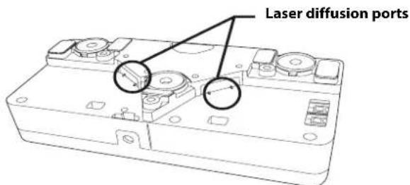
| Do not apply optical devices such as a magnifying glass or telescope to the laser light diffused from the Touch Unit. If such optical devices are applied, it could cause personal injury or fire. | |
| Do not look into the Touch Unit's laser diffusion ports. This could cause injury to eyesight. Extra care should be taken when children are present. | |
| Do not view the laser light using optical devices such as a magnifying glass within a range of 2.75 inches (70 mm). Viewing at close range could cause injury to eyesight. | |
| Connect the Touch Unit to BrightLink 595Wi/595Wi+ and BrightLink Pro 1430Wi models only. Do not connect it to any other projectors or devices. |

Warning
Do not use the Touch Unit if you are using or near medical equipment such as a pacemaker.
The magnet within the Touch Unit generates electromagnetic interference which could cause medical equipment to malfunction.

Caution
Do not install the wall mount in a location where the operating temperature for your projector model may be exceeded. Such an environment may damage the projector.

Install the wall mount in a place free from excessive dust and humidity to prevent the lens or optical components from becoming dirty.

Do not use excessive force when adjusting the wall mount.

The wall mount may break, resulting in personal injury.

Keep magnetic storage media (for example, magnetic cards or electronic devices such as computers, digital watches, or cell phones) away from the Touch Unit.
The magnet within the Touch Unit generates electromagnetic interference which could corrupt data or cause the media or device to malfunction.
Installation Location
- Before installing the projector, verify the power supply wiring for the installation location.
- Install the projector away from other electric devices such as fluorescent lights or air conditioners. Some kinds of fluorescent lights could interfere with the remote control of the projector.
- Install the projector away from direct sunlight and other bright light sources.
It is recommended to keep VGA computer cable length less than 65 ft (20 meters) to reduce external noise. - Install the projector in a location where the projected image is within reach.
-
The projector must be installed in one of the following locations in order for the Touch Unit to function properly:
-
Mounted on a wall or suspended from the ceiling with images projected from in front of the screen.
-
Mounted vertically on a table with images projected from the front of the table. If using this installation method, you need the optional interactive table mount (ELPMB29) and attachment plate (ELPPT05).
-
When powering the Control Pad using batteries, verify that the installation location meets the following conditions:
-
Install the Control Pad on the same surface as the projection screen. If the projection screen and the Control Pad installation point are uneven, install the Control Pad approximately 8 in (20 cm) from the edge of the screen.
-
Make sure there are no obstacles between the Control Pad and the projector (not including the Touch Unit).
-
Use the optional Remote Control Cable Set (model ELPKC28, part number V12H005C28) to supply power to the Control Pad in the following situations:
-
The required conditions above are not met.
- The projection screen and the Control Pad installation point are uneven and the difference in height is more than 2 inches (5 cm).
- The projector is placed on a table and projecting to the screen.
- Multiple projectors are being used.
Before installing the Touch Unit, verify that the installation location meets the following conditions:
- The Touch Unit can be secured to the surface with magnets or screws.
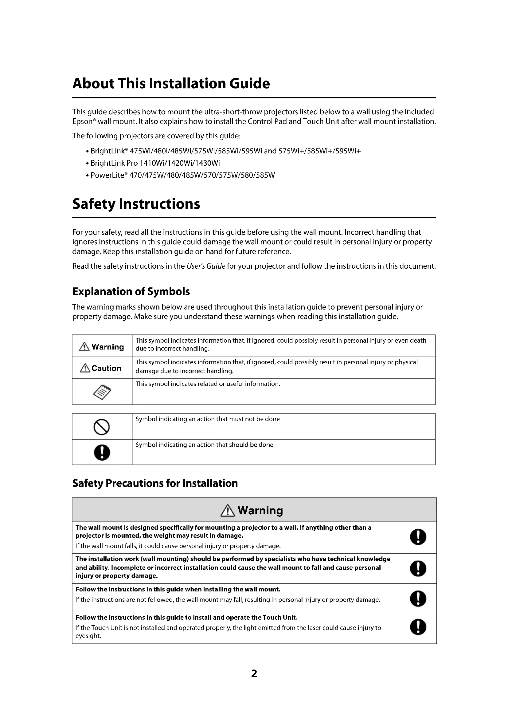
- The surface is flat, smooth, and unwarped with no more than 0.2 inches (5 mm) of unevenness in any direction on the screen surface.
- When installing on a whiteboard, install the Touch Unit within the frame of the whiteboard.
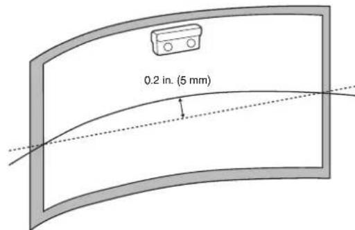
Correct position Incorrect position
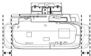
Make sure there are no obstacles, such as cables, or protruding objects such as whiteboard trays, pen holders, or thick frames in the shaded areas in the following figure. The Touch Unit will not operate correctly if anything is obstructing the infrared signal.
1 Package Contents

2 Specifications

3 Connecting Devices

4 Positioning the Projector

- Installation worksheet for projecting on a pre-installed wall-mounted board
- Installation worksheet for projecting on a plain wall
- Diagonal image size and mounting position
- Distance from projection surface to wall plate
- Installation measurement tables
- Installation Measurements in Inches for WXGA Projectors
- Installation Measurements in Inches for XGA Projectors
- Installation Measurements in Millimeters for WXGA Projectors
- Installation Measurements in Millimeters for XGA Projectors
5 Installing the Projector

- Disassemble the parts
- Assemble the parts
- Install the wall plate on the wall
- Determine the projection distance and pull out the slider
- Route the cables through the wall mount arm
- Attach the mount arm to the wall plate
- Adjust the vertical slide position of the arm
- Attach the projector to the wall mount
- Connect the power cord and other cables to the projector
6 Adjusting the Image
41
- Turn on the projector
- Display the test pattern
- Change the aspect ratio if necessary
- Adjust the focus
- Use the adjustment knob on the left side to adjust the horizontal roll
- Use the adjustment knob on the right side to adjust the horizontal rotation
- Use the adjustment knob on the top to adjust the vertical tilt
- Adjust the horizontal slide
- Adjust the forward/backward slide
- Adjust the vertical slide
- Turn off the display of the test pattern
7 Attaching the Covers
47
- Attach the wall plate cover and end cap
- Attach the cable cover to the projector
8 Installing the Touch Unit
49
- Turn on the projector
- Display the installation pattern
- Remove the markers
- Determine the installation position for the Touch Unit
- Install the Touch Unit
- Connect the cable
- Adjust the angle
- Store the markers and attach labels
- Attach cover
9 Installing the Control Pad
62
- Remove the cable cover
- Attach the Control Pad
- Install the batteries
- Connect the projector cables to the Control Pad
- Attach the port protection stickers
- Attach the cable cover
10 Appendix
66
- Using the Easy Interactive Function
- Attaching a Security Cable
Wall Mount
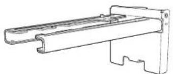
Wall mount
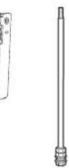
Hexagonal shaft
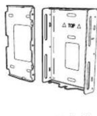
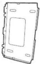
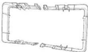
Wall plate
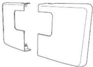
Wall plate cover
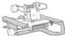
3-axis adjustment unit and slide plate (attached when shipped)
Wall plate cover extender
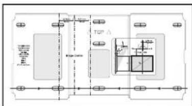
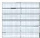
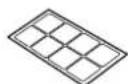
Template sheet (for installing the wall plate)
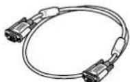
VGA computer cable (may be included with projector or wall mount)

Open-ended wrench 13 mm (for M8 and M6) × 6 mm (for hexagonal shaft)
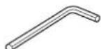
Hexagon wrench (for M4)
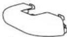
End cap
| Shape Name | Quantity Application | ||
| M4 × 12 mm hexagon socket head cap bolt with washer/spring washer | 6 For wall plate assembly | ||
| 4 For 3-axis adjustment unit/wall mount installation | |||
| 4 For slide plate/projector installation | |||
| 2 For slide plate/3-axis adjustment unit installation (secured when shipped) | |||
| M6 × 20 mm hexagon shoulder bolt with washer/spring washer | 1 For wall mount/wall plate installation | ||
| M6 × 20 mm cross recessed head shoulder screw with plastic washer | 3 | ||
- Use the bolts or screws supplied with the wall mount to install it as directed in this guide. Do not substitute these bolts with any other types.
- You need to use commercially available M10 × 60 mm anchors (at least 3) to attach the wall plate to the wall.
- Gather the tools and parts you need before you begin installation, including a #3 cross-head screwdriver.
Touch Unit
The following parts are packaged with your projector and are necessary when attaching the Touch Unit. When installing the Touch Unit on a non-magnetic surface, you will also need three M4 screws.
Touch Unit and markers (markers are inside the unit)


Spacer for screw hole (× 3)
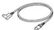
Touch Unit connection cable
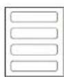
Label (x4)
Tape (approx. 2.4 inches [6 cm]) for securing the markers (× 12)
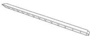
Infrared deflector (approx. 11.2 inches [28.5 cm]) (× 8)
Control Pad
The following parts are packaged with your projector and are necessary when attaching the Control Pad. When installing the Control Pad on a wall, you will also need four M4 × 20 mm screws.
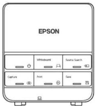
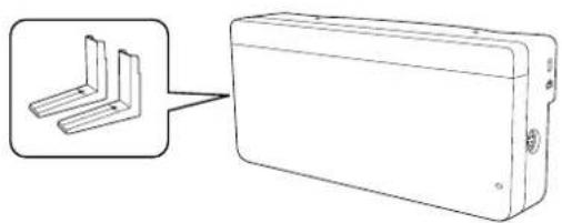
Control Pad

AA size batteries (× 2) Port prot8cbnner feet
stickers
| Item | Specification | Additional information | Reference Page |
| Wall mount weight (including the 3-axis adjustment unit, slide plate, wall plate, wall plate cover, wall plate cover extender, and end cap) | Approx. 18.5 lb (8.4 kg) | Wall mount: 6.6 lb (3.0 kg)3-axis adjustment unit: 2.6 lb (1.2 kg)Slide plate: 1.8 lb (0.8 kg)Wall plate: 6.0 lb (2.7 kg)Wall plate cover and end cap: 0.9 lb (0.4 kg)Wall plate cover extender: 0.6 lb (0.3 kg) | — |
| Maximum load capacity 15.4 lb (7 kg) — — | |||
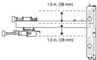
| Vertical slide adjustment range ± 1.5 in. (38 mm) — Refer to the | illustration below | ||
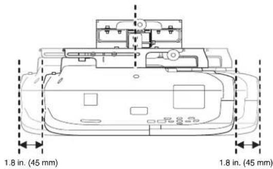
| Horizontal slide adjustment range ± 1.8 in. (45 mm) — Refer to the | illustration on page 11 | ||
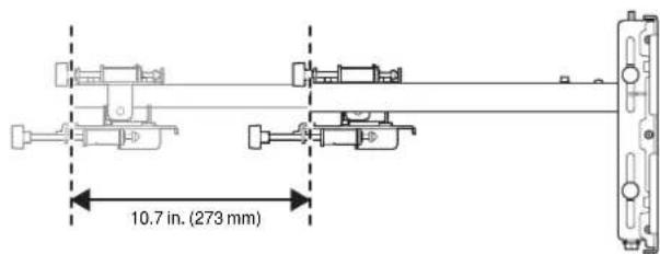
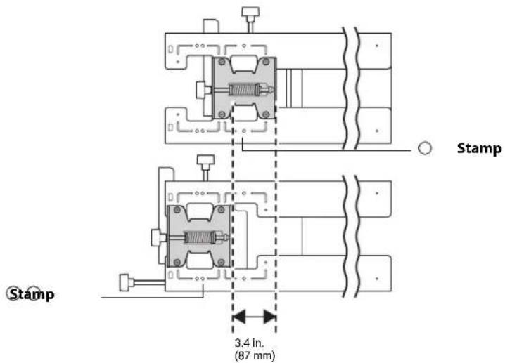
| Forward/backward slide adjustment range | 0 to 14.2 in.(360 mm) | Arm slide adjustment range: 0 to 10.7 in. (273 mm)Adjustment from 3-axis adjustment unit installation position: 3.4 in. (87 mm) | Refer to the illustration on page 11 |
| Horizontal roll adjustment range ± 3° Fine adjustments possible with adjustment knob | p. 44 | ||
| Horizontal rotation adjustment range | ± 8° Fine adjustments possible with adjustment knob | p. 44 | |
| Vertical tilt adjustment range | ± 3° Fine adjustments possible with adjustment knob | p. 45 | |
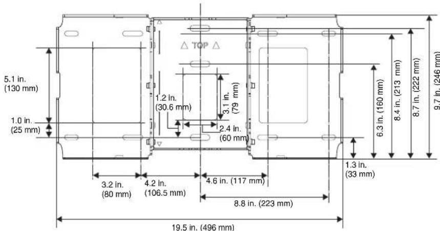
Wall plate
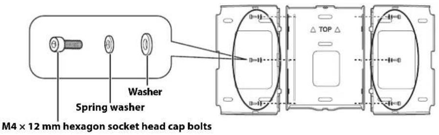
The wall plate is in three pieces when shipped. Use the included M4 × 12 mm bolts (×6) to attach the separate pieces together before mounting the projector. See page 31 for instructions.
Vertical slide adjustment range
Horizontal slide adjustment range
Forward/backward slide adjustment range
Arm slide adjustment range
Adjustment from 3-axis adjustment unit installation position
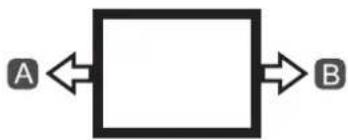
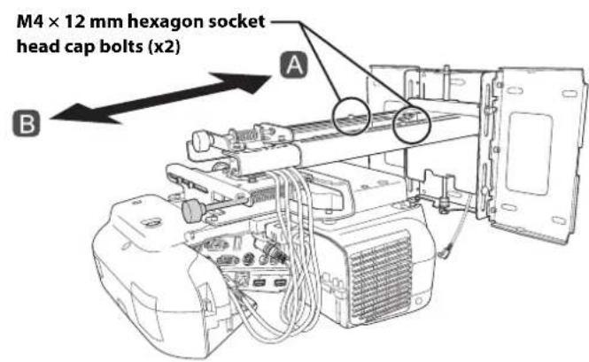
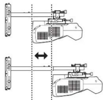
By changing the installation position of the 3-axis adjustment unit to the front or back, you can adjust the installation position of the projector.
When the screen size is less than 75 inches, install it at the position marked with a stamp on the mount arm.
When the screen size is 75 inches or more, install it at the position marked with a stamp on the mount arm.
To see these stamps, you need to remove the two top screws and slide out the arm extension.
Touch Unit
External dimensions and weight
The Touch Unit weighs approximately 16 ounces (450 g).
Attached labels
The Touch Unit is a Class 1 laser product that conforms to the JIS C 6802:2011 standard. There are warning labels affixed to the Touch Unit to indicate that it is a Class 1 laser product. The labels contain the following information:
- Invisible laser radiation
- Do not view the beam directly with optical instruments
Class 1 laser product
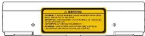
The laser beam is diffused from the laser diffusion ports on the back of the Touch Unit.
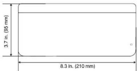
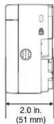
Control Pad
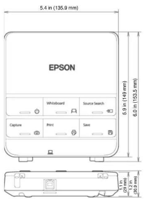
External dimensions and weight
The Control Pad weighs approximately 8.5 ounces (240 g).
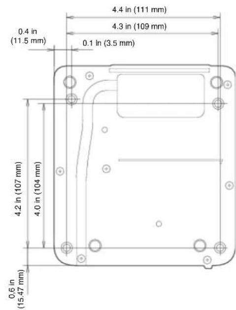
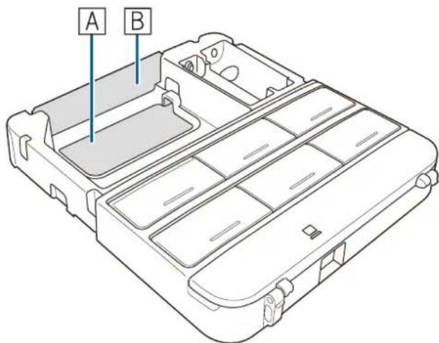
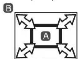
Cable routing holes
When routing cables through a wall, use the position (A) in the following figure as the cable routing hole.
Otherwise, remove the cable cover (B) and route the cables through the opening. Route the printer cable along the groove on the back of the Control Pad.
Make sure you have the power cord, computer cable, and other parts at the location where the wall mount is to be installed.
Make sure you also have all necessary cables for the Touch Unit and other devices, such as a document camera or microphone, that you will connect to the projector. Your projector's connection panel may differ slightly from the displayed model. For details, refer to the online User's Guide for your projector.
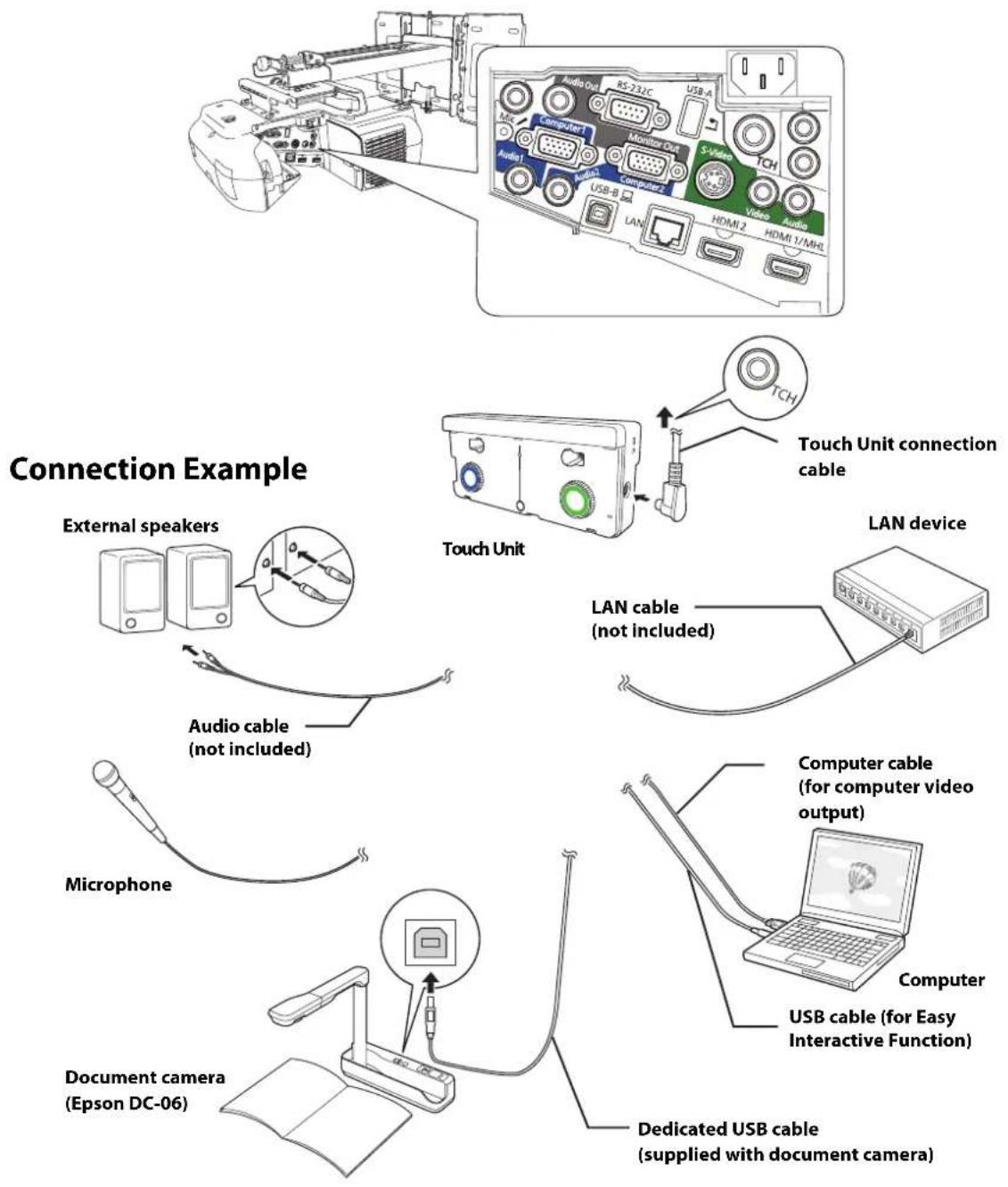
For Interactive Use
When interacting with a computer, you need a USB cable. However, when using the projector's built-in toolbar, you do not need a USB cable.
Connecting the Control Pad
The Control Pad is included with the BrightLink Pro 1410Wi/1420Wi/1430Wi projectors. It provides a convenient alternative to the remote control for turning on the projector, changing the source, and selecting whiteboard mode. You can also use the control pad to capture, print, and save your projected images.
You must install the control pad on the same surface as the projector, within the range specified in the installation instructions. You can use the included batteries to power the control pad, or the optional remote control cable set (model ELPKC28, part number V12H005C28).
See "Installing the Control Pad" on page 62 for instructions.
BrightLink Pro 1410Wi/1420Wi/1430Wi, BrightLink 475W/485W, BrightLink 575Wi/585Wi/595Wi, BrightLink 575Wi+/585Wi+/595Wi+ and PowerLite 475W/485W/575W/585W can project up to 100 inches diagonally for a WXGA image or 88 inches diagonally for an XGA image. The BrightLink 480i and PowerLite 470/480/570/580 can project up to 93 inches diagonally for an XGA image.
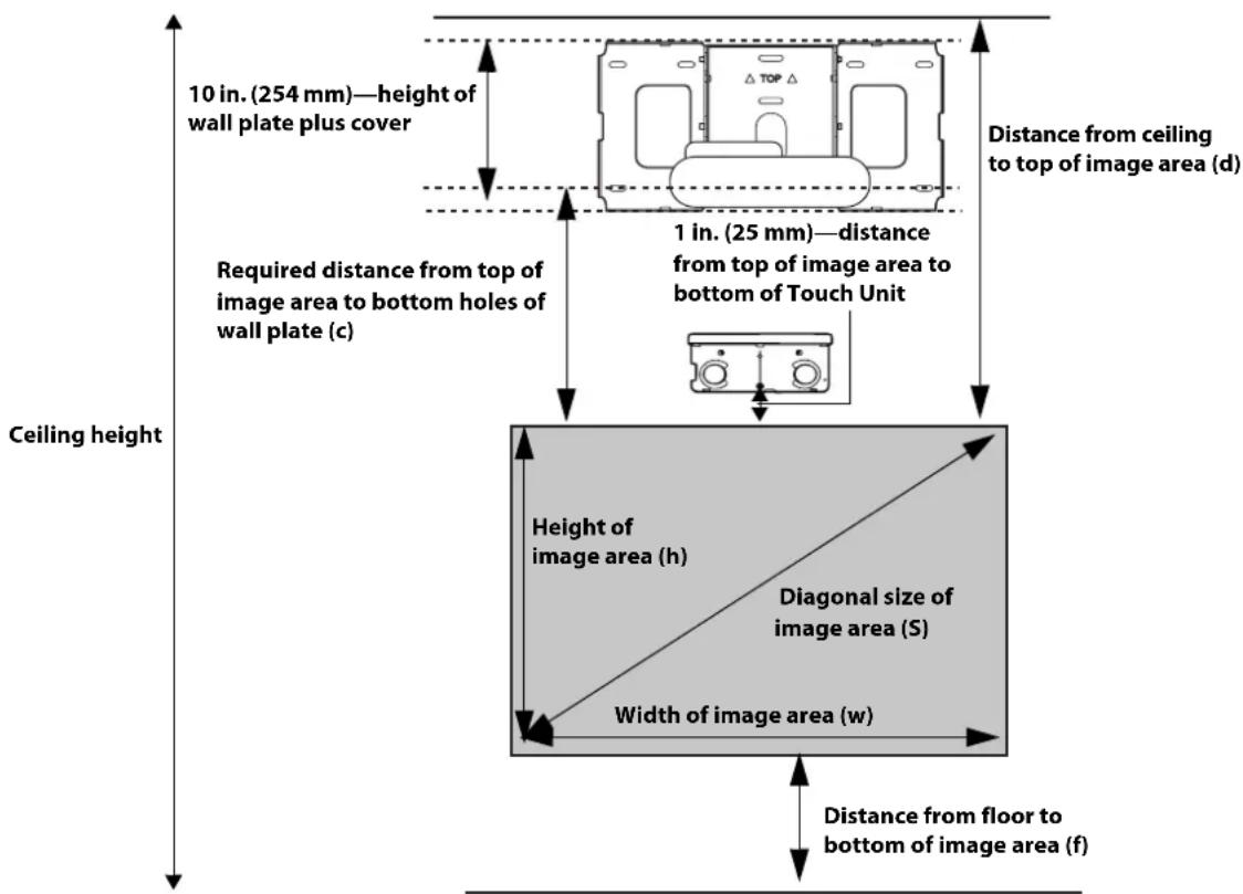
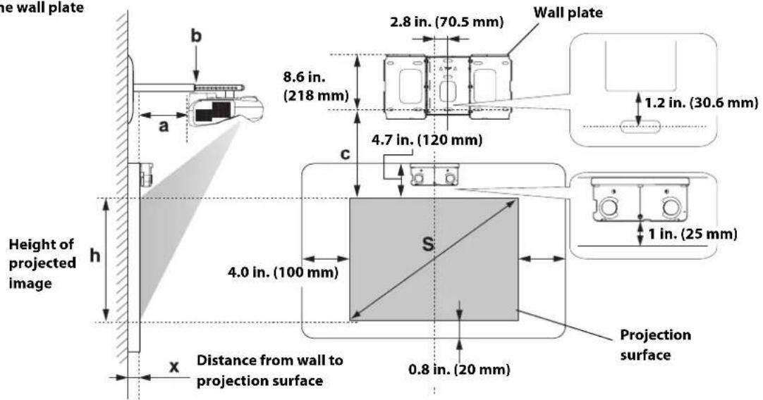
You can project onto a pre-installed whiteboard or directly onto a plain wall. When installing the Touch Unit, install it on the screen that is being used for projection; you need at least 4.7 inches (120 mm) between the top edge of the projected image and the top edge of the screen. The height of the included wall mount determines the maximum image size and how high the image appears on the wall or whiteboard. The distance of the projector from the wall (once it is mounted on the adjustable arm of the wall mount) also affects image size and position.
If you are planning to project on a whiteboard, the image may not fill the entire board, depending on the aspect ratio. If you match the image height to the board's height, gaps may appear on the sides of the board.
Use the following worksheets to determine the proper location of the wall plate on the wall. If you are projecting onto a pre-installed whiteboard, use the worksheet on page 17. If you are projecting on a plain wall, use the worksheet on page 18.

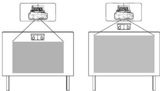
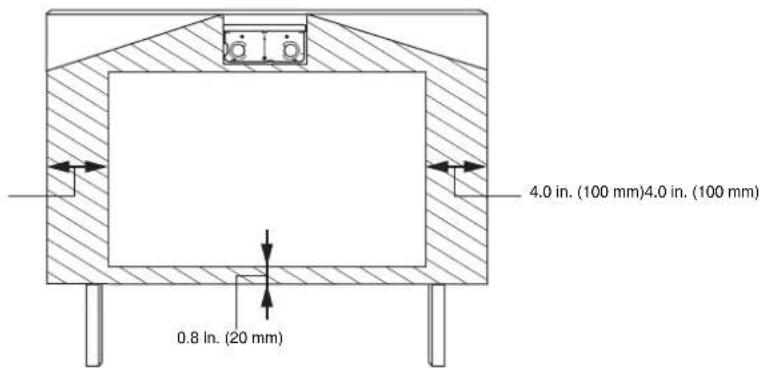
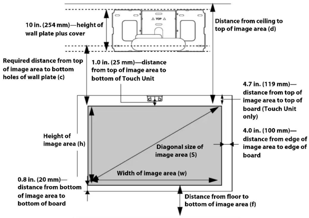
When installing on a whiteboard, make sure to leave the following gaps around the edge of the board:
From the top of the projected image to the bottom of the Touch Unit: 1 inch (25 mm)
From the edges of the projected image to the edges of the board: at least 4 inches (100 mm) left and right
□From the bottom of the projected image to the bottom of the board: 0.8 inches (20 mm)
If there are obstacles such as cables, whiteboard trays, pen holders, or frames within the areas listed above, the Touch Unit will not operate properly.
Installation worksheet for projecting on a pre-installed wall-mounted board
- Measure the ceiling height (distance from the floor to the ceiling).
2.Measure the height of the board's image area (h). (h)
3.Measure the width of the board's image area (w). (w) - Measure the distance from the floor to the bottom of the board's image area (f). (f)
- Measure the distance from the ceiling to the top of the board's image area (d). (d)
- Measure the thickness of the board (distance from the projection surface to the wall) (x). (x)
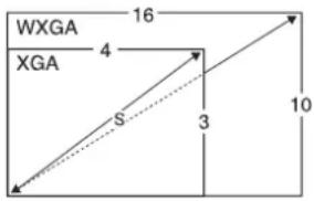
- Determine the aspect ratio of the board or of the images that will be projected. For new computers or laptops, this will most likely be WXGA (16:10). For older equipment, this will most likely be XGA (4:3). You may need to consult your IT department for this information.
4:3XGA
16:10WXGA
16:9 Widescreen
-
Using the tables on pages 21 to 28 for your aspect ratio and desired image height (h), find the required distance between the top of the image area and the bottom holes of ______ (c) the wall plate (c).
-
Determine the position for your projector installation by adding the values for (f), (h), and (c), plus an additional 10 inches for the height of the wall plate plus the cover. (h)
If the ceiling height of your room (as noted in step 1) does not meet the minimum ceiling height required for your board, you may need to select a smaller image size or move the board to a lower position on the wall.
(c)
+10 inches
total
- After confirming your image size, use tape or a pencil to mark the distance (c) from the top of the image area on the board to the bottom holes of the wall plate.
- Align the line (horizontal) on the template sheet with the (c) mark, then align the center line on the template sheet with the center of the image area. Follow the instructions on page 30 to install the projector.
Installation worksheet for projecting on a plain wall
- Measure the ceiling height (distance from the floor to the ceiling).
- Determine the desired aspect ratio of the image. For new computers or laptops, this will most likely be WXGA (16:10). For older equipment, this will most likely be XGA (4:3). You may need to consult your IT department for this information.
4:3XGA
16:10WXGA
16:9 Widescreen
- Using the tables on pages 21 to 25 for your aspect ratio, select the largest image size available for your ceiling height.
Image height (h) (h)
Image width (w)
- Determine the desired distance from the floor to the bottom of the image area (f).
The recommended minimum distance is 30 inches. Images appearing less than 28 inches from the floor may be obstructed for some viewers.
- Find the top of the projected image area by adding distances (f) and (h).
-
Use the tables on pages 21 to 28 to determine the required distance from the top of the image area to the bottom holes of the wall plate (c). (c)
-
Add:
Required distance from top of image area to bottom holes of wall plate (c) (c)
Height of image area (h) (h)
Distance from floor to bottom of image area (f)
Height of wall plate plus cover +10 inches
If the total exceeds the ceiling height, you will need to reduce the image size or reduce ______ total the distance from the floor to the bottom of the image area.
- After confirming your image size, use tape or a pencil to mark the distance (c) from the top of the image area on the board to the bottom holes of the wall plate.
- Align the line (horizontal) on the template sheet with the (c) mark, then align the center line on the template sheet with the center of the image area. Follow the instructions on page 30 to install the projector.
The tables on the following pages provide installation information for all supported image sizes. The minimum ceiling height is based on an image 30 inches from the floor; if the image is lower, the minimum ceiling height is reduced by the corresponding measurement.
Use the worksheets, the illustrations, and the information in the tables on the following pages to determine the projection distance and placement of the wall plate. The recommended range for projection distance (a) as shown on the following pages is 2.5 to 12.2 inches (62 to 311mm ).
Diagonal image size and mounting position
The numbers on the slider measure (b) are the same as the projection distance (a) when the diagonal image size (S) is 75 inches or more. Because the installation position of the projector changes when (S) is less than 75 inches, the numbers for (a) and (b) differ.
Offset value for the position of the center of the screen and the center of the wall plate
In order to see the stamp and the numbers on the slider scale, you need to slide out the arm extension.
When the diagonal image size is 75 inches or more, mount the 3-axis adjustment unit at the position marked with a Stamp .
When the diagonal image size is less than 75 inches, mount the 3-axis adjustment unit at the position marked with a stamp.
Distance from projection surface to wall plate
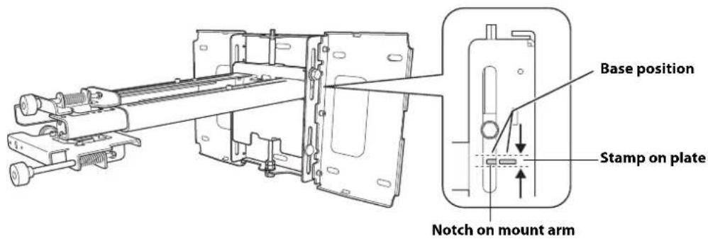
The distance (c) from the projection surface to the bottom mounting holes on the wall plate is the number given when the vertical slide is set to the base position, as shown below.
Match the notch on the wall mount to the position of the stamp on the wall plate.
Installation measurement tables
Use the following table to determine which installation measurement table to use for your projector.
| Projectile model Maximum image | size (diagonal) | Installation measurement table |
| BrightLink Pro 1410Wi/1420Wi/1430Wi | 100 WXGA | |
| BrightLink 475W/485W/575Wi/585Wi/595Wi | ||
| BrightLink 575Wi+/585Wi+/595Wi+ | ||
| PowerLite 475W/485W/575W/585W | ||
| BrightLink 480i | 93 XGA | |
| PowerLite 470/480/570/580 |

The measurements may differ depending on the location where you place the projector.
When projecting in Tele, the quality of the projected images may decrease.
When using a WXGA projector to project images at a 4:3 aspect ratio, the images are resized automatically and the quality of the projected images may decrease.
When the wall plate cover extender is installed, the minimum diagonal image size is increased to: WXGA 67" (16:10), 65" (16:9), 59" (4:3); XGA 62" (4:3), 57" (16:9), 59" (16:10).
Installation Measurements in Inches for WXGA Projectors
| Diagonal image size (S) | 16:10 WXGA 4:3 XGA 16:9 Widescreen | n | |||||||||||||||||
| Min. ceiling height* | Image width (w) | Image height (h) | Min. projection distance (a) | Slider scale mark (b) | Distance from top of image to wall plate holes (c) | Min. ceiling height* | Image width (w) | Image height (h) | Min. projection distance (a) | Slider scale mark (b) | Distance from top of image to wall plate holes (c) | Min. ceiling height* | Image width (w) | Image height (h) | Min. projection distance (a) | Slider scale mark (b) | Distance from top of image to wall plate holes (c) | ||
| 53"— | — | — | — | — | — | — | 78.7 | 42.4 | 31.8 | 2.5 | 5.9 | 6.9 | — | — | — | — | — | — | |
| 54"— | — | — | — | — | — | — | 79.4 | 43.2 | 32.4 | 2.7 | 6.1 | 7.0 | — | — | — | — | — | — | |
| 55"— | — | — | — | — | — | — | 80.1 | 44.0 | 33.0 | 3.0 | 6.4 | 7.1 | — | — | — | — | — | — | |
| 56"— | — | — | — | — | — | — | 80.8 | 44.8 | 33.6 | 3.3 | 6.7 | 7.2 | — | — | — | — | — | — | |
| 57"— | — | — | — | — | — | — | 81.5 | 45.6 | 34.2 | 3.6 | 7.0 | 7.3 | — | — | — | — | — | — | |
| 58" | — | — | — | — | — | — | 82.3 | 46.4 | 34.8 | 3.8 | 7.3 | 7.5 | — | — | — | — | — | — | |
| 59" | — | — | — | — | — | — | 83.0 | 47.2 | 35.4 | 4.1 | 7.6 | 7.6 | 77.5 | 51.4 | 28.9 | 2.6 | 6.0 | 8.5 | |
| 60" | 78.7 | 50.9 | 31.8 | 2.5 | 5.9 | 6.9 | 83.7 | 48.0 | 36.0 | 4.4 | 7.8 | 7.7 | 78.1 | 52.3 | 29.4 | 2.9 | 6.3 | 8.7 | |
| 61" | 79.3 | 51.7 | 32.3 | 2.7 | 6.1 | 7.0 | 84.4 | 48.8 | 36.6 | 4.7 | 8.1 | 7.8 | 78.7 | 53.2 | 29.9 | 3.1 | 6.5 | 8.8 | |
| 62" | 79.9 | 52.6 | 32.9 | 3.0 | 6.4 | 7.1 | 85.1 | 49.6 | 37.2 | 5.0 | 8.4 | 7.9 | 79.3 | 54.0 | 30.4 | 3.4 | 6.8 | 8.9 | |
| 63" | 80.6 | 53.4 | 33.4 | 3.2 | 6.6 | 7.2 | 85.8 | 50.4 | 37.8 | 5.2 | 8.7 | 8.0 | 80.0 | 54.9 | 30.9 | 3.6 | 7.0 | 9.1 | |
| 64" | 81.2 | 54.3 | 33.9 | 3.4 | 6.9 | 7.3 | 86.6 | 51.2 | 38.4 | 5.5 | 8.9 | 8.2 | 80.6 | 55.8 | 31.4 | 3.9 | 7.3 | 9.2 | |
| 65" | 81.8 | 55.1 | 34.4 | 3.7 | 7.1 | 7.4 | 87.3 | 52.0 | 39.0 | 5.8 | 9.2 | 8.3 | 81.2 | 56.7 | 31.9 | 4.1 | 7.6 | 9.3 | |
| 66" | 82.5 | 56.0 | 35.0 | 3.9 | 7.4 | 7.5 | 88.0 | 52.8 | 39.6 | 6.1 | 9.5 | 8.4 | 81.8 | 57.5 | 32.4 | 4.4 | 7.8 | 9.5 | |
| 67" | 83.1 | 56.8 | 35.5 | 4.2 | 7.6 | 7.6 | 88.7 | 53.6 | 40.2 | 6.3 | 9.8 | 8.5 | 82.5 | 58.4 | 32.9 | 4.6 | 8.0 | 9.6 | |
| 68" | 83.7 | 57.7 | 36.0 | 4.4 | 7.8 | 7.7 | 89.4 | 54.4 | 40.8 | 6.6 | 10.0 | 8.6 | 83.1 | 59.3 | 33.3 | 4.9 | 8.3 | 9.7 | |
| 69" | 84.4 | 58.5 | 36.6 | 4.7 | 8.1 | 7.8 | 90.2 | 55.2 | 41.4 | 6.9 | 10.3 | 8.8 | 83.7 | 60.1 | 33.8 | 5.1 | 8.5 | 9.9 | |
| 70" | 85.0 | 59.4 | 37.1 | 4.9 | 8.3 | 7.9 | 90.9 | 56.0 | 42.0 | 7.2 | 10.6 | 8.9 | 84.3 | 61.0 | 34.3 | 5.4 | 8.8 | 10.0 | |
| 71" | 85.6 | 60.2 | 37.6 | 5.1 | 8.6 | 8.0 | 91.6 | 56.8 | 42.6 | 7.4 | 10.9 | 9.0 | 85.0 | 61.9 | 34.8 | 5.6 | 9.1 | 10.2 | |
| 72" | 86.3 | 61.1 | 38.2 | 5.4 | 8.8 | 8.1 | 92.3 | 57.6 | 43.2 | 7.7 | 11.1 | 9.1 | 85.6 | 62.8 | 35.3 | 5.9 | 9.3 | 10.3 | |
| 73" | 86.9 | 61.9 | 38.7 | 5.6 | 9.1 | 8.2 | 93.0 | 58.4 | 43.8 | 8.0 | 11.4 | 9.2 | 86.2 | 63.6 | 35.8 | 6.1 | 9.6 | 10.4 | |
| 74" | 87.5 | 62.8 | 39.2 | 5.9 | 9.3 | 8.3 | 93.8 | 59.2 | 44.4 | 8.3 | 11.7 | 9.4 | 86.8 | 64.5 | 36.3 | 6.4 | 9.8 | 10.6 | |
| 75" | 88.2 | 63.6 | 39.7 | 6.1 | 6.1 | 8.4 | 94.5 | 60.0 | 45.0 | 8.5 | 8.5 | 9.5 | 87.5 | 65.4 | 36.8 | 6.6 | 6.6 | 10.7 | |
| 76" | 88.8 | 64.4 | 40.3 | 6.4 | 6.4 | 8.5 | 95.2 | 60.8 | 45.6 | 8.8 | 8.8 | 9.6 | 88.1 | 66.2 | 37.3 | 6.9 | 6.9 | 10.8 | |
| Diagonal image size (S) | 16:10 WXGA | 4:3 XGA | 16:9 Widescreen | |||||||||||||||
| Min. ceiling height* | Image width (w) | Image height (h) | Min. projection distance (a) | Slider scale mark (b) | Distance from top of image to wall plate holes (c) | Min. ceiling height* | Image width (w) | Image height (h) | Min. projection distance (a) | Slider scale mark (b) | Distance from top of image to wall plate holes (c) | Min. ceiling height* | Image width (w) | Image height (h) | Min. projection distance (a) | Slider scale mark (b) | Distance from top of image to wall plate holes (c) | |
| 77" | 89.5 | 65.3 | 40.8 | 6.6 | 6.6 | 8.6 | 95.9 | 61.6 | 46.2 | 9.1 | 9.1 | 9.7 | 88.7 | 67.1 | 37.8 | 7.1 | 7.1 | 11.0 |
| 78" | 90.1 | 66.1 | 41.3 | 6.9 | 6.9 | 8.8 | 96.6 | 62.4 | 46.8 | 9.4 | 9.4 | 9.8 | 89.3 | 68.0 | 38.2 | 7.4 | 7.4 | 11.1 |
| 79" | 90.7 | 67.0 | 41.9 | 7.1 | 7.1 | 8.9 | 97.4 | 63.2 | 47.4 | 9.7 | 9.7 | 10.0 | 90.0 | 68.9 | 38.7 | 7.6 | 7.6 | 11.2 |
| 80" | 91.4 | 67.8 | 42.4 | 7.3 | 7.3 | 9.0 | 98.1 | 64.0 | 48.0 | 9.9 | 9.9 | 10.1 | 90.6 | 69.7 | 39.2 | 7.9 | 7.9 | 11.4 |
| 81" | 92.0 | 68.7 | 42.9 | 7.6 | 7.6 | 9.1 | 98.8 | 64.8 | 48.6 | 10.2 | 10.2 | 10.2 | 91.2 | 70.6 | 39.7 | 8.1 | 8.1 | 11.5 |
| 82" | 92.6 | 69.5 | 43.5 | 7.8 | 7.8 | 9.2 | 99.5 | 65.6 | 49.2 | 10.5 | 10.5 | 10.3 | 91.8 | 71.5 | 40.2 | 8.4 | 8.4 | 11.6 |
| 83" | 93.3 | 70.4 | 44.0 | 8.1 | 8.1 | 9.3 | 100.2 | 66.4 | 49.8 | 10.8 | 10.8 | 10.4 | 92.5 | 72.3 | 40.7 | 8.6 | 8.6 | 11.8 |
| 84" | 93.9 | 71.2 | 44.5 | 8.3 | 8.3 | 9.4 | 100.9 | 67.2 | 50.4 | 11.0 | 11.0 | 10.5 | 93.1 | 73.2 | 41.2 | 8.9 | 8.9 | 11.9 |
| 85" | 94.5 | 72.1 | 45.0 | 8.6 | 8.6 | 9.5 | 101.7 | 68.0 | 51.0 | 11.3 | 11.3 | 10.7 | 93.7 | 74.1 | 41.7 | 9.1 9.1 | 12.0 | |
| 86" | 95.2 | 72.9 | 45.6 | 8.8 | 8.8 | 9.6 | 102.4 | 68.8 | 51.6 | 11.6 | 11.6 | 10.8 | 94.3 | 75.0 | 42.2 | 9.4 9.4 | 12.2 | |
| 87" | 95.8 | 73.8 | 46.1 | 9.1 | 9.1 | 9.7 | 103.1 | 69.6 | 52.2 | 11.9 | 11.9 | 10.9 | 95.0 | 75.8 | 42.7 | 9.6 9.6 | 12.3 | |
| 88" | 96.4 | 74.6 | 46.6 | 9.3 | 9.3 | 9.8 | 103.8 | 70.4 | 52.8 | 12.1 | 12.1 | 11.0 | 95.6 | 76.7 | 43.1 | 9.9 9.9 | 12.5 | |
| 89" | 97.1 | 75.5 | 47.2 | 9.5 | 9.5 | 9.9 | - | - | - | - | - | - | 96.2 | 77.6 | 43.6 | 10.2 | 10.2 12.6 | |
| 90" | 97.7 | 76.3 | 47.7 | 9.6 | 9.6 | 10.0 | - | - | - | - | - | - | 96.8 | 78.4 | 44.1 | 10.4 | 10.4 12.7 | |
| 91" | 98.3 | 77.2 | 48.2 | 10.0 | 10.0 | 10.1 | - | - | - | - | - | - | 97.5 | 79.3 | 44.6 | 10.7 | 10.7 12.9 | |
| 92" | 99.0 | 78.0 | 48.8 | 10.3 | 10.3 | 10.2 | - | - | - | - | - | - | 98.1 | 80.2 | 45.1 | 10.9 | 10.9 | 13.0 |
| 93" | 99.6 | 78.9 | 49.3 | 10.5 | 10.5 | 10.3 | - | - | - | - | - | - | 98.7 | 81.1 | 45.6 | 11.2 | 11.2 | 13.1 |
| 94" | 100.3 | 79.7 | 49.8 | 10.8 | 10.8 | 10.4 | - | - | - | - | - | - | 99.3 | 81.9 | 46.1 | 11.4 | 11.4 | 13.3 |
| 95" | 100.9 | 80.6 | 50.3 | 11.0 | 11.0 | 10.5 | - | - | - | - | - | - | 100.0 | 82.8 | 46.6 | 11.7 | 11.7 | 13.4 |
| 96" | 101.5 | 81.4 | 50.9 | 11.3 | 11.3 | 10.6 | - | - | - | - | - | - | 100.6 | 83.7 | 47.1 | 11.9 | 11.9 | 13.5 |
| 97" | 102.2 | 82.3 | 51.4 | 11.5 | 11.5 | 10.7 | - | - | - | - | - | - | 101.2 | 84.5 | 47.6 | 12.2 | 12.2 | 13.7 |
| 98" | 102.8 | 83.1 | 51.9 | 11.7 | 11.7 | 10.9 | - | - | - | - | - | - | - | - | - | - | - | - |
| 99" | 103.4 | 84.0 | 52.5 | 12.0 | 12.0 | 11.0 | - | - | - | - | - | - | - | - | - | - | - | - |
| 100" | 104.1 | 84.8 | 53.0 | 12.2 | 12.2 | 11.1 | - | - | - | - | - | - | - | - | - | - | - | - |
- Based on an image 30 inches from the floor; if the image is lower, the minimum ceiling height is reduced by the corresponding measurement.
Installation Measurements in Inches for XGA Projectors
| Diagonal image size (S) | 4:3 XGA 16:10 WXGA 16:9 Widesc | teen | ||||||||||||||||
| Min. ceiling height* | Image width (w) | Image height (h) | Min. projection distance (a) | Slider scale mark (b) | Distance from top of image to wall plate holes (c) | Min. ceiling height* | Image width (w) | Image height (h) | Min. projection distance (a) | Slider scale mark (b) | Distance from top of image to wall plate holes(c) | Min. ceiling height* | Image width (w) | Image height (h) | Min. projection distance (a) | Slider scale mark (b) | Distance from top of image to wall plate holes (c) | |
| 52"— | — | — | — | — | — | — | — | 75.8 — | 45.3 | 25.5 | 2.6 | 6.1 | 10.3 | |||||
| 53"— | — | — | — | — | — | 76.9 | 44.9 | 28.1 | 2.5 | 5.9 | 8.8 | 76.4 | 46.2 | 26.0 | 2.9 | 6.3 | 10.5 | |
| 54"— | — | — | — | — | — | 77.6 | 45.8 | 28.6 | 2.8 | 6.2 | 9.0 | 77.1 | 47.1 | 26.5 | 3.2 | 6.6 | 10.7 | |
| 55"— | — | — | — | — | — | 78.2 | 46.6 | 29.2 | 3.1 | 6.5 | 9.1 | 77.8 | 47.9 | 27.0 | 3.5 | 6.9 | 10.8 | |
| 56" | 79.6 | 44.8 | 33.6 | 2.5 | 5.9 | 6.0 | 78.9 | 47.5 | 29.7 | 3.4 | 6.8 | 9.3 | 78.5 | 48.8 | 27.5 | 3.8 | 7.2 | 11.0 |
| 57" | 80.3 | 45.6 | 34.2 | 2.7 | 6.1 | 6.1 | 79.6 | 48.3 | 30.2 | 3.6 | 7.0 | 9.4 | 79.2 | 49.7 | 27.9 | 4.1 | 7.5 | 11.2 |
| 58" | 80.9 | 46.4 | 34.8 | 3.0 | 6.4 | 6.2 | 80.3 | 49.2 | 30.7 | 3.9 | 7.3 | 9.6 | 79.8 | 50.6 | 28.4 | 4.4 | 7.8 | 11.4 |
| 59" | 81.7 | 47.2 | 35.4 | 3.3 | 6.7 | 6.3 | 81.0 | 50.0 | 31.3 | 4.2 | 7.6 | 9.7 | 80.5 | 51.4 | 28.9 | 4.6 | 8.1 | 11.6 |
| 60" | 82.3 | 48.0 | 36.0 | 3.5 | 6.9 | 6.4 | 81.7 | 50.9 | 31.8 | 4.5 | 7.9 | 9.9 | 81.2 | 52.3 | 29.4 | 4.9 | 8.3 | 11.8 |
| 61" | 83.1 | 48.8 | 36.6 | 3.8 | 7.2 | 6.5 | 82.4 | 51.7 | 32.3 | 4.7 | 8.1 | 10.0 | 81.9 | 53.2 | 29.9 | 5.2 | 8.6 | 12.0 |
| 62" | 83.7 | 49.6 | 37.2 | 4.1 | 7.5 | 6.6 | 83.1 | 52.6 | 32.9 | 5.0 | 8.4 | 10.2 | 82.6 | 54.0 | 30.4 | 5.5 | 8.9 | 12.2 |
| 63" | 84.4 | 50.4 | 37.8 | 4.3 | 7.7 | 6.6 | 83.7 | 53.4 | 33.4 | 5.3 | 8.7 | 10.4 | 83.2 | 54.9 | 30.9 | 5.8 | 9.2 | 12.3 |
| 64" | 85.1 | 51.2 | 38.4 | 4.6 | 8.0 | 6.7 | 84.4 | 54.3 | 33.9 | 5.6 | 9.0 | 10.5 | 83.9 | 55.8 | 31.4 | 6.1 | 9.5 | 12.5 |
| 65" | 85.9 | 52.0 | 39.0 | 4.8 | 8.2 | 6.8 | 85.1 | 55.1 | 34.4 | 5.8 | 9.3 | 10.7 | 84.6 | 56.7 | 31.9 | 6.4 | 9.8 | 12.7 |
| 66" | 86.5 | 52.8 | 39.6 | 5.1 | 8.5 | 6.9 | 85.8 | 56.0 | 35.0 | 6.1 | 9.5 | 10.8 | 85.3 | 57.5 | 32.4 | 6.6 | 10.0 | 12.9 |
| 67" | 87.2 | 53.6 | 40.2 | 5.4 | 8.8 | 7.0 | 86.5 | 56.8 | 35.5 | 6.4 | 9.8 | 11.0 | 85.9 | 58.4 | 32.9 | 6.9 | 10.4 | 13.1 |
| 68" | 87.9 | 54.4 | 40.8 | 5.6 | 9.0 | 7.1 | 87.2 | 57.7 | 36.0 | 6.7 | 10.1 | 11.1 | 86.6 | 59.3 | 33.3 | 7.2 | 10.6 | 13.3 |
| 69" | 88.6 | 55.2 | 41.4 | 5.9 | 9.3 | 7.2 | 87.9 | 58.5 | 36.6 | 7.0 | 10.4 | 11.3 | 87.3 | 60.1 | 33.8 | 7.5 | 10.9 | 13.5 |
| 70" | 89.3 | 56.0 | 42.0 | 6.1 | 9.6 | 7.3 | 88.5 | 59.4 | 37.1 | 7.2 | 10.7 | 11.4 | 88.0 | 61.0 | 34.3 | 7.8 | 11.2 | 13.7 |
| 71" | 90.0 | 56.8 | 42.6 | 6.4 | 9.8 | 7.4 | 89.2 | 60.2 | 37.6 | 7.5 | 10.9 | 11.6 | 88.6 | 61.9 | 34.8 | 8.1 | 11.5 | 13.8 |
| 72" | 90.7 | 57.6 | 43.2 | 6.7 | 10.1 | 7.5 | 89.9 | 61.1 | 38.2 | 7.8 | 11.2 | 11.8 | 89.3 | 62.8 | 35.3 | 8.3 | 11.6 | 14.0 |
| 73" | 91.4 | 58.4 | 43.8 | 6.9 | 10.4 | 7.6 | 90.6 | 61.9 | 38.7 | 8.1 | 11.5 | 11.9 | 90.0 | 63.6 | 35.8 | 8.6 | 12.0 | 14.2 |
| 74" | 92.1 | 59.2 | 44.4 | 7.2 | 10.6 | 7.7 | 91.3 | 62.8 | 39.2 | 8.3 | 11.8 | 12.1 | 90.7 | 64.5 | 36.3 | 8.9 | 12.3 | 14.4 |
| Diagonal image size (S) | 4:3 XGA | 16:10 WXGA | 16:9 Widescreen | |||||||||||||||
| Min. ceiling height* | Image width (w) | Image height (h) | Min. projection distance (a) | Slider scale mark (b) | Distance from top of image to wall plate holes (c) | Min. ceiling height* | Image width (w) | Image height (h) | Min. projectio distance (a) | Slider scale mark (b) | Distance from top of image to wall plate holes(c) | Min. ceiling height* | Image width (w) | Image height (h) | Min. projection distance (a) | Slider scale mark (b) | Distance from top of image to wall plate holes (c) | |
| 75" | 92.8 | 60.0 | 45.0 | 7.4 | 7.4 | 7.8 | 92.0 | 63.6 | 39.7 | 8.6 | 8.6 | 12.2 | 91.4 | 65.4 | 36.8 | 9.2 | 9.2 | 14.6 |
| 76" | 93.5 | 60.8 | 45.6 | 7.7 | 7.7 | 7.9 | 92.6 | 64.4 | 40.3 | 8.9 | 8.9 | 12.4 | 92.0 | 66.2 | 37.3 | 9.5 | 9.5 | 14.8 |
| 77" | 94.2 | 61.6 | 46.2 | 8.0 | 8.0 | 8.0 | 93.3 | 65.3 | 40.8 | 9.2 | 9.2 | 12.5 | 92.7 | 67.1 | 37.8 | 9.8 | 9.8 | 15.0 |
| 78" | 94.9 | 62.4 | 46.8 | 8.2 | 8.2 | 8.1 | 94.0 | 66.1 | 41.3 | 9.5 | 9.5 | 12.7 | 93.4 | 68.0 | 38.2 | 10.1 | 10.1 | 15.1 |
| 79" | 95.6 | 63.2 | 47.4 | 8.5 | 8.5 | 8.2 | 94.7 | 67.0 | 41.9 | 9.7 | 9.7 | 12.8 | 94.1 | 68.9 | 38.7 | 10.3 | 10.3 | 15.3 |
| 80" | 96.3 | 64.0 | 48.0 | 8.8 | 8.8 | 8.3 | 95.4 | 67.8 | 42.4 | 10.0 | 10.0 | 13.0 | 94.7 | 69.7 | 39.2 | 10.6 | 10.6 | 15.5 |
| 81" | 97.0 | 64.8 | 48.6 | 9.0 | 9.0 | 8.4 | 96.1 | 68.7 | 42.9 | 10.3 | 10.3 | 13.2 | 95.4 | 70.6 | 39.7 | 10.9 | 10.9 | 15.7 |
| 82" | 97.7 | 65.6 | 49.2 | 9.3 | 9.3 | 8.5 | 96.8 | 69.5 | 43.5 | 10.6 | 10.6 | 13.3 | 96.1 | 71.5 | 40.2 | 11.2 | 11.2 | 15.9 |
| 83" | 98.4 | 66.4 | 49.8 | 9.5 | 9.5 | 8.6 | 97.4 | 70.4 | 44.0 | 10.8 | 10.8 | 13.5 | 96.8 | 72.3 | 40.7 | 11.5 | 11.5 | 16.1 |
| 84" | 99.1 | 67.2 | 50.4 | 9.8 | 9.8 | 8.7 | 98.1 | 71.2 | 44.5 | 11.1 | 11.1 | 13.6 | 97.5 | 73.2 | 41.2 | 11.8 | 11.8 | 16.3 |
| 85" | 99.8 | 68.0 | 51.0 | 10.1 | 10.1 | 8.8 | 98.8 | 72.1 | 45.0 | 11.4 | 11.4 | 13.8 | 98.1 | 74.1 | 41.7 | 12.1 12.1 | 16.5 | |
| 86" | 100.5 | 68.8 | 51.6 | 10.3 | 10.3 | 8.9 | 99.5 | 72.9 | 45.6 | 11.7 | 11.7 | 13.9 | - | - | - | - | - | - |
| 87" | 101.2 | 69.6 | 52.2 | 10.6 | 10.6 | 9.0 | 100.2 | 73.8 | 46.1 | 12.0 | 12.0 | 14.1 | - | - | - | - | - | - |
| 88" | 101.9 | 70.4 | 52.8 | 10.9 | 10.9 | 9.1 | 100.9 | 74.6 | 46.6 | 12.2 | 12.2 | 14.2 | - | - | - | - | - | - |
| 89" | 102.6 | 71.2 | 53.4 | 11.1 | 11.1 | 9.2 | - | - | - | - | - | - | - | - | - | - | - | - |
| 90" | 103.3 | 72.0 | 54.0 | 11.4 | 11.4 | 9.3 | - | - | - | - | - | - | - | - | - | - | - | - |
| 91" | 104.0 | 72.8 | 54.6 | 11.6 | 11.6 | 9.4 | - | - | - | - | - | - | - | - | - | - | - | - |
| 92" | 104.6 | 73.6 | 55.2 | 11.9 | 11.9 | 9.5 | - | - | - | - | - | - | - | - | - | - | - | - |
| 93" | 105.3 | 74.4 | 55.8 | 12.2 | 12.2 | 9.6 | - | - | - | - | - | - | - | - | - | - | - | - |
- Based on an image 30 inches from the floor; if the image is lower, the minimum ceiling height is reduced by the corresponding measurement.
Installation Measurements in Millimeters for WXGA Projectors
| Diagonal image size(S) | 16:10 WXGA 4:3 XGA 16:9 Widescreen | |||||||||||||||||
| Min. ceiling height* | Image width(w) | Image height(h) | Min. projection distance(a) | Slider scale mark(b) | Distance from top of image to wall plate holes(c) | Min. ceiling height* | Image width(w) | Image height(h) | Min. projection distance(a) | Slider scale mark(b) | Distance from top of image to wall plate holes(c) | Min. ceiling height* | Image width(w) | Image height(h) | Min. Projection distance(a) | Slider scale mark(b) | Distance from top of image to wall plate holes(c) | |
| 53"— | — | — | — | — | — | — | 1998 1077 | 808 62 | 149 174 | — | — | — | — | — | — | — | — | — |
| 54"— | — | — | — | — | — | — | 2016 1097 | 823 69 | 156 177 | — | — | — | — | — | — | — | — | — |
| 55"— | — | — | — | — | — | — | 2034 1118 | 838 76 | 163 180 | — | — | — | — | — | — | — | — | — |
| 56"— | — | — | — | — | — | — | 2052 1138 | 853 83 | 170 183 | — | — | — | — | — | — | — | — | — |
| 57"— | — | — | — | — | — | — | 2071 1158 | 869 91 | 178 186 | — | — | — | — | — | — | — | — | — |
| 58"— | — | — | — | — | — | — | 2089 1179 | 884 98 | 185 189 | — | — | — | — | — | — | — | — | — |
| 59"— | — | — | — | — | — | — | 2107 | 1199 | 899 | 105 | 192 | 192 | 1968 | 1306 | 735 | 66 | 153 | 217 |
| 60" | 1998 | 1292 | 808 | 62 | 149 | 174 | 2125 | 1219 | 914 | 112 | 199 | 195 | 1983 | 1328 | 747 | 73 | 160 | 220 |
| 61" | 2014 | 1314 | 821 | 69 | 156 | 177 | 2144 | 1240 | 930 | 119 | 206 | 198 | 1999 | 1350 | 760 | 79 | 166 | 223 |
| 62" | 2030 | 1335 | 835 | 75 | 162 | 179 | 2162 | 1260 | 945 | 126 | 213 | 201 | 2015 | 1373 | 772 | 86 | 173 | 227 |
| 63" | 2046 | 1357 | 848 | 81 | 168 | 182 | 2180 | 1280 | 960 | 133 | 220 | 204 | 2031 | 1395 | 785 | 92 | 179 | 230 |
| 64" | 2063 | 1379 | 862 | 87 | 174 | 185 | 2198 | 1300 | 975 | 140 | 227 | 207 | 2047 | 1417 | 797 | 98 | 185 | 234 |
| 65" | 2078 | 1400 | 875 | 93 | 180 | 187 | 2217 | 1321 | 991 | 147 | 234 | 210 | 2062 | 1439 | 809 | 105 | 192 | 237 |
| 66" | 2094 | 1422 | 888 | 100 | 187 | 190 | 2235 | 1341 | 1006 | 154 | 241 | 213 | 2079 | 1461 | 822 | 111 | 198 | 241 |
| 67" | 2111 | 1443 | 902 | 106 | 193 | 193 | 2253 | 1361 | 1021 | 161 | 248 | 216 | 2094 | 1483 | 834 | 117 | 204 | 244 |
| 68" | 2126 | 1465 | 915 | 112 | 199 | 195 | 2271 | 1382 | 1036 | 168 | 256 | 219 | 2111 | 1505 | 847 | 124 | 211 | 248 |
| 69" | 2143 | 1486 | 929 | 118 | 205 | 198 | 2290 | 1402 | 1052 | 175 | 262 | 222 | 2126 | 1528 | 859 | 130 | 217 | 251 |
| 70" | 2159 | 1508 | 942 | 124 | 211 | 201 | 2308 | 1422 | 1067 | 182 | 269 | 225 | 2142 | 1550 | 872 | 137 | 224 | 254 |
| 71" | 2175 | 1529 | 956 | 131 | 218 | 203 | 2326 | 1443 | 1082 | 189 | 276 | 228 | 2158 | 1572 | 884 | 143 | 230 | 258 |
| 72" | 2191 | 1551 | 969 | 137 | 224 | 206 | 2345 | 1463 | 1097 | 196 | 283 | 232 | 2174 | 1594 | 897 | 149 | 236 | 261 |
| 73" | 2208 | 1572 | 983 | 143 | 230 | 209 | 2364 | 1483 | 1113 | 203 | 290 | 235 | 2190 | 1616 | 909 | 156 | 243 | 265 |
| 74" | 2223 | 1594 | 996 | 149 | 236 | 211 | 2382 | 1504 | 1128 | 210 | 297 | 238 | 2205 | 1638 | 921 | 162 | 249 | 268 |
| 75" | 2240 | 1615 | 1010 | 155 | 155 | 214 | 2400 | 1524 | 1143 | 217 | 217 | 241 | 2222 | 1660 | 934 | 168 | 168 | 272 |
| 76" | 2256 | 1637 | 1023 | 162 | 162 | 217 | 2418 | 1544 | 1158 | 224 | 224 | 244 | 2237 | 1682 | 946 | 175 | 175 | 275 |
| Diagonal image size (S) | 16:10 WXGA | 4:3 XGA | 16:9 Widescreen | |||||||||||||||
| Min. ceiling height* | Image width (w) | Image height (h) | Min. projection distance (a) | Slider scale mark (b) | Distance from top of image to wall plate holes (c) | Min. ceiling height* | Image width (w) | Image height (h) | Min. projection distance (a) | Slider scale mark (b) | Distance from top of image to wall plate holes (c) | Min. ceiling height* | Image width (w) | Image height (h) | Min. Projection distance (a) | Slider scale mark (b) | Distance from top of image to wall plate holes (c) | |
| 77" | 2272 | 1659 | 1037 | 168 | 168 | 219 | 2436 | 1565 | 1173 | 231 | 231 | 247 | 2253 | 1705 | 959 | 181 | 181 | 278 |
| 78" | 2288 | 1680 | 1050 | 174 | 174 | 222 | 2455 | 1585 | 1189 | 238 | 238 | 250 | 2269 | 1727 | 971 | 188 | 188 | 282 |
| 79" | 2304 | 1702 | 1063 | 180 | 180 | 225 | 2473 | 1605 | 1204 | 245 | 245 | 253 | 2285 | 1749 | 984 | 194 | 194 | 285 |
| 80" | 2320 | 1723 | 1077 | 187 | 187 | 227 | 2491 | 1626 | 1219 | 252 | 252 | 256 | 2301 | 1771 | 996 | 200 | 200 | 289 |
| 81" | 2336 | 1745 | 1090 | 193 | 193 | 230 | 2509 | 1646 | 1234 | 259 | 259 | 259 | 2317 | 1793 | 1009 | 207 | 207 | 292 |
| 82" | 2353 | 1766 | 1104 | 199 | 199 | 233 | 2528 | 1666 | 1250 | 266 | 266 | 262 | 2333 | 1815 | 1021 | 213 | 213 | 296 |
| 83" | 2368 | 1788 | 1117 | 205 | 205 | 235 | 2546 | 1687 | 1265 | 273 | 273 | 265 | 2349 | 1837 | 1034 | 219 | 219 | 299 |
| 84" | 2385 | 1809 | 1131 | 211 | 211 | 238 | 2564 | 1707 | 1280 | 280 | 280 | 268 | 2365 | 1860 | 1046 | 226 | 226 | 303 |
| 85" | 2401 | 1831 | 1144 | 218 | 218 | 241 | 2582 | 1727 | 1295 | 287 | 287 | 271 | 2380 | 1882 | 1058 | 232 | 232 | 306 |
| 86" | 2417 | 1852 | 1158 | 224 | 224 | 243 | 2601 | 1748 | 1311 | 294 | 294 | 274 | 2396 | 1904 | 1071 | 239 | 239 | 309 |
| 87" | 2433 | 1874 | 1171 | 230 | 230 | 246 | 2619 | 1768 | 1326 | 301 | 301 | 277 | 2412 | 1926 | 1083 | 245 | 245 | 313 |
| 88" | 2450 | 1895 | 1185 | 236 | 236 | 249 | 2637 | 1788 | 1341 | 308 | 308 | 280 | 2428 | 1948 | 1096 | 251 | 251 | 316 |
| 89" | 2466 | 1917 | 1198 | 242 | 242 | 252 | — | — | — | — | — | — | 2444 | 1970 | 1108 | 258 | 258 | 320 |
| 90" | 2482 | 1939 | 1212 | 249 | 249 | 254 | — | — | — | — | — | — | 2460 | 1992 | 1121 | 264 | 264 | 323 |
| 91" | 2498 | 1960 | 1225 | 255 | 255 | 257 | — | — | — | — | — | — | 2476 | 2015 | 1133 | 270 | 270 | 327 |
| 92" | 2515 | 1982 | 1239 | 261 | 261 | 260 | — | — | — | — | — | — | 2492 | 2037 | 1146 | 277 | 277 | 330 |
| 93" | 2530 | 2003 | 1252 | 267 | 267 | 262 | — | — | — | — | — | — | 2507 | 2059 | 1158 | 283 | 283 | 333 |
| 94" | 2546 | 2025 | 1265 | 273 | 273 | 265 | — | — | — | — | — | — | 2524 | 2081 | 1171 | 290 | 290 | 337 |
| 95" | 2563 | 2046 | 1279 | 280 | 280 | 268 | — | — | — | — | — | — | 2539 | 2103 | 1183 | 296 | 296 | 340 |
| 96" | 2578 | 2068 | 1292 | 286 | 286 | 270 | — | — | — | — | — | — | 2555 | 2125 | 1195 | 302 | 302 | 344 |
| 97" | 2595 | 2089 | 1306 | 292 | 292 | 273 | — | — | — | — | — | — | 2571 | 2147 | 1208 | 309 | 309 | 347 |
| 98" | 2611 | 2111 | 1319 | 298 | 298 | 276 | — | — | — | — | — | — | — | — | — | — | — | — |
| 99" | 2627 | 2132 | 1333 | 304 | 304 | 278 | — | — | — | — | — | — | — | — | — | — | — | — |
| 100" | 2643 | 2154 | 1346 | 311 | 311 | 281 | — | — | — | — | — | — | — | — | — | — | — | — |
- Based on an image 762 mm from the floor; if the image is lower, the minimum ceiling height is reduced by the corresponding measurement.
Installation Measurements in Millimeters for XGA Projectors
| Diagonal image size (S) | 4:3 XGA 16:10 WXGA 16:9 Widescreen | |||||||||||||||||
| Min. ceiling height* | Image width (w) | Image height (h) | Min. projection distance (a) | Slider scale mark (b) | Distance from top of image to wall plate holes (c) | Min. ceiling height* | Image width (w) | Image height (h) | Min. projection distance (a) | Slider scale mark (b) | Distance from top of image to wall plate holes (c) | Min. ceiling height* | Image width (w) | Image height (h) | Min. Projection distance (a) | Slider scale mark (b) | Distance from top of image to wall plate holes (c) | |
| 52" | — | — | — | — | — | — | — | — | — | — | — | — | 1925 | 1151 | 648 | 67 | 154 | 261 |
| 53" | — | — | — | — | — | — | 1952 | 1142 | 713 | 64 | 151 | 223 | 1942 | 1173 | 660 | 74 | 161 | 266 |
| 54" | — | — | — | — | — | — | 1970 | 1163 | 727 | 71 | 158 | 227 | 1959 | 1195 | 672 | 81 | 168 | 271 |
| 55" | — | — | — | — | — | — | 1987 | 1185 | 740 | 78 | 165 | 231 | 1976 | 1218 | 685 | 89 | 176 | 275 |
| 56" | 2021 | 1138 | 853 | 63 | 150 | 152 | 2005 | 1206 | 754 | 85 | 172 | 235 | 1993 | 1240 | 697 | 96 | 183 | 280 |
| 57" | 2039 | 1158 | 869 | 69 | 156 | 154 | 2022 | 1228 | 767 | 92 | 179 | 239 | 2011 | 1262 | 710 | 103 | 190 | 285 |
| 58" | 2056 | 1179 | 884 | 76 | 163 | 156 | 2040 | 1249 | 781 | 99 | 186 | 243 | 2028 | 1284 | 722 | 110 | 197 | 290 |
| 59" | 2074 | 1199 | 899 | 83 | 170 | 159 | 2057 | 1271 | 794 | 106 | 193 | 247 | 2045 | 1306 | 735 | 118 | 205 | 294 |
| 60" | 2091 | 1219 | 914 | 89 | 176 | 161 | 2075 | 1292 | 808 | 113 | 200 | 251 | 2062 | 1328 | 747 | 125 | 212 | 299 |
| 61" | 2110 | 1240 | 930 | 96 | 183 | 164 | 2092 | 1314 | 821 | 120 | 207 | 255 | 2080 | 1350 | 760 | 132 | 219 | 304 |
| 62" | 2127 | 1260 | 945 | 103 | 190 | 166 | 2110 | 1335 | 835 | 127 | 214 | 259 | 2097 | 1373 | 772 | 139 | 226 | 309 |
| 63" | 2145 | 1280 | 960 | 109 | 196 | 169 | 2127 | 1357 | 848 | 134 | 221 | 263 | 2114 | 1395 | 785 | 147 | 234 | 313 |
| 64" | 2162 | 1300 | 975 | 116 | 203 | 171 | 2145 | 1379 | 862 | 141 | 228 | 267 | 2131 | 1417 | 797 | 154 | 241 | 318 |
| 65" | 2181 | 1321 | 991 | 122 | 209 | 174 | 2162 | 1400 | 875 | 148 | 235 | 271 | 2148 | 1439 | 809 | 161 | 248 | 323 |
| 66" | 2198 | 1341 | 1006 | 129 | 216 | 176 | 2179 | 1422 | 888 | 155 | 242 | 275 | 2166 | 1461 | 822 | 168 | 255 | 328 |
| 67" | 2216 | 1361 | 1021 | 136 | 223 | 179 | 2197 | 1443 | 902 | 163 | 250 | 279 | 2182 | 1483 | 834 | 176 | 263 | 332 |
| 68" | 2233 | 1382 | 1036 | 142 | 229 | 181 | 2214 | 1465 | 915 | 170 | 257 | 283 | 2200 | 1505 | 847 | 183 | 270 | 337 |
| 69" | 2251 | 1402 | 1052 | 149 | 236 | 183 | 2232 | 1486 | 929 | 177 | 264 | 287 | 2217 | 1528 | 859 | 190 | 277 | 342 |
| 70" | 2269 | 1422 | 1067 | 156 | 243 | 186 | 2249 | 1508 | 942 | 184 | 271 | 291 | 2235 | 1550 | 872 | 197 | 284 | 347 |
| 71" | 2286 | 1443 | 1082 | 162 | 249 | 188 | 2266 | 1529 | 956 | 191 | 278 | 294 | 2251 | 1572 | 884 | 205 | 292 | 351 |
| 72" | 2304 | 1463 | 1097 | 169 | 256 | 191 | 2283 | 1551 | 969 | 198 | 285 | 298 | 2269 | 1594 | 897 | 212 | 294 | 356 |
| 73" | 2322 | 1483 | 1113 | 176 | 263 | 193 | 2301 | 1572 | 983 | 205 | 292 | 302 | 2286 | 1616 | 909 | 219 | 306 | 361 |
| 74" | 2340 | 1504 | 1128 | 182 | 269 | 196 | 2318 | 1594 | 996 | 212 | 299 | 306 | 2303 | 1638 | 921 | 226 | 313 | 366 |
| Diagonal image size (S) | 4:3 XGA | 16:10 WXGA | 16:9 Widescreen | |||||||||||||||
| Min. ceiling height* | Image width (w) | Image height (h) | Min. projection distance (a) | Slider scale mark (b) | Distance from top of image to wall plate holes (c) | Min. ceiling height* | Image width (w) | Image height (h) | Min. projection distance (a) | Slider scale mark (b) | Distance from top of image to wall plate holes (c) | Min. ceiling height* | Image width (w) | Image height (h) | Min. Projection distance (a) | Slider scale mark (b) | Distance from top of image to wall plate holes (c) | |
| 75" | 2357 | 1524 | 1143 | 189 | 189 | 198 | 2336 | 1615 | 1010 | 219 | 219 | 310 | 2320 | 1660 | 934 | 234 | 234 | 370 |
| 76" | 2375 | 1544 | 1158 | 196 | 196 | 201 | 2353 | 1637 | 1023 | 226 | 226 | 314 | 2337 | 1682 | 946 | 241 | 241 | 375 |
| 77" | 2392 | 1565 | 1173 | 202 | 202 | 203 | 2371 | 1659 | 1037 | 233 | 233 | 318 | 2355 | 1705 | 959 | 248 | 248 | 380 |
| 78" | 2411 | 1585 | 1189 | 209 | 209 | 206 | 2388 | 1680 | 1050 | 240 | 240 | 322 | 2372 | 1727 | 971 | 255 | 255 | 385 |
| 79" | 2428 | 1605 | 1204 | 216 | 216 | 208 | 2405 | 1702 | 1063 | 247 | 247 | 326 | 2389 | 1749 | 984 | 263 | 263 | 389 |
| 80" | 2446 | 1626 | 1219 | 222 | 222 | 211 | 2423 | 1723 | 1077 | 254 | 254 | 330 | 2406 | 1771 | 996 | 270 | 270 | 394 |
| 81" | 2463 | 1646 | 1234 | 229 | 229 | 213 | 2440 | 1745 | 1090 | 261 | 261 | 334 | 2424 | 1793 | 1009 | 277 | 277 | 399 |
| 82" | 2481 | 1666 | 1250 | 236 | 236 | 215 | 2458 | 1766 | 1104 | 268 | 268 | 338 | 2441 | 1815 | 1021 | 284 | 284 | 404 |
| 83" | 2499 | 1687 | 1265 | 242 | 242 | 218 | 2475 | 1788 | 1117 | 275 | 275 | 342 | 2458 | 1837 | 1034 | 292 | 292 | 408 |
| 84" | 2516 | 1707 | 1280 | 249 | 249 | 220 | 2493 | 1809 | 1131 | 282 | 282 | 346 | 2475 | 1860 | 1046 | 299 | 299 | 413 |
| 85" | 2534 | 1727 | 1295 | 256 | 256 | 223 | 2510 | 1831 | 1144 | 289 | 289 | 350 | 2492 | 1882 | 1058 | 306 | 306 | 418 |
| 86" | 2552 | 1748 | 1311 | 262 | 262 | 225 | 2528 | 1852 | 1158 | 297 | 297 | 354 | — | — | — | — | — | — |
| 87" | 2570 | 1768 | 1326 | 269 | 269 | 228 | 2545 | 1874 | 1171 | 304 | 304 | 358 | — | — | — | — | — | — |
| 88" | 2587 | 1788 | 1341 | 275 | 275 | 230 | 2563 | 1895 | 1185 | 311 | 311 | 362 | — | — | — | — | — | — |
| 89" | 2605 | 1808 | 1356 | 282 | 282 | 233 | — | — | — | — | — | — | — | — | — | — | — | — |
| 90" | 2623 | 1829 | 1372 | 289 | 289 | 235 | — | — | — | — | — | — | — | — | — | — | — | — |
| 91" | 2641 | 1849 | 1387 | 295 | 295 | 238 | — | — | — | — | — | — | — | — | — | — | — | — |
| 92" | 2658 | 1869 | 1402 | 302 | 302 | 240 | — | — | — | — | — | — | — | — | — | — | — | — |
| 93" | 2675 | 1890 | 1417 | 309 | 309 | 242 | — | — | — | — | — | — | — | — | — | — | — | — |
- Based on an image 762 mm from the floor; if the image is lower, the minimum ceiling height is reduced by the corresponding measurement.
If you have a pre-existing interactive whiteboard, refer to the table below to identify common models and sizes. If your board is listed here, use the dimensions to reference the installation requirements found on pages 21 to 28.
Interactive whiteboard sizes
| Diagonal size | 16:10 WXGA | 4:3 XGA | 16:9 Widescreen |
| 57 inches — PolyVision | TS410 — | ||
| 60 inches — Hitachi® | Cambridge board 60 | RM ClassBoard2 60INTERWRITE BOARD 1060INTERWRITE Dual board 1260 | — |
| 63 inches — Hitachi® | StarBoard FX-63 — | ||
| 64 inches — SMART Board 660 | Prometheus ActivBoard 164 | — | |
| 66 inches — TeamBoard RT TMWM5422CL/EM — | |||
| 71 inches — INTERWRITE BOARD 1071 | |||
| 75 inches PolyVision® | eno2650 — | ||
| 77 inches — Hitachi | Cambridge Board 77 | Hitachi StarBoard FX DUO 77SMART Board 680SMART BoardX880INTERWRITE® BOARD 1077TeamBoard RT TMWM6250CL/EM | INTERWRITE Dual board 1277 |
| 77.5 inches — RM ClassBoard2 77.5 — | |||
| 78 inches PolyVision | TS 600/ TS620 / TSL620 PolyVision TS610Prometheus ActivBoard 178 / 378 | — | |
| 79 inches — INTERWRITE Dual Board 1279 — | |||
| 80 inches — RM Classboard 85 | |||
| 82 inches — Hitachi StarBoard FX-82W | |||
| 85 inches TeamBoard | RT TMWM7450EM — INTERWRITE BOARD 1085 | INTERWRITE Dual Board 1285 | |
| 87 inches | SMART Board™ 685SMART BoardX 885Prometheus ActivBoard 387Prometheus ActivBoard 587 pro | — | — |
| 88 inches Hitachi StarBoard FX DUO-88W — — | |||
| 89 inches — INTERWRITE Dual Board 1289 — | |||
| 93 inches — PolyVision ENO 2810 | |||
| 94 inches — SMART Board 690 | |||
| 95 inches — INTERWRITE BOARD 1095 | INTERWRITE Dual Board 1295Prometheus ActivBoard 395Prometheus ActivBoard 595 pro | ||
Make sure to follow the steps below to install the wall mount. If you ignore these steps, the wall mount could fall and cause personal injury or property damage.
Warning
- When you mount the projector on the wall with the wall mount, the wall requires enough strength to hold the projector and the wall mount.
This wall mount should be installed on a concrete wall. Confirm the weight of the projector and the wall mount before installation, and maintain the strength of the wall. If the wall is not strong enough, reinforce the wall before installation.
The maximum combined weight of the projector and the wall mount is 32.6 lb (14.8 kg).
Do not hang the rest of the cable over the wall mount.
Install the wall mount so that it can sufficiently support the weight of the projector and wall mount, and resist any horizontal vibration. Use M10 nuts and bolts and make sure to use appropriate wall anchors for your wall type. Nuts and bolts smaller than M10 could cause the wall mount to fall.
Epson accepts no responsibility for any damage or injury caused by lack of wall strength or inadequate installation.
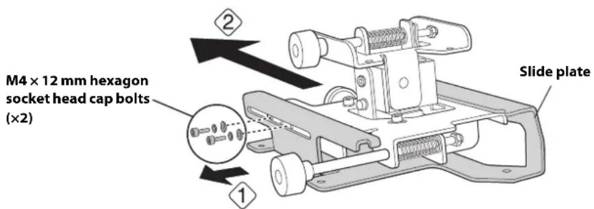
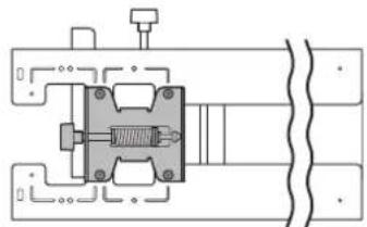
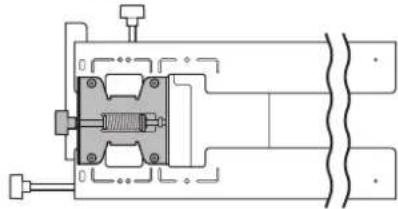
Disassemble the parts
Remove the slide plate from the 3-axis adjustment unit.
- Remove the M4 × 12 mm hexagon socket head cap bolts (x2) ()
- Remove the slide plate from the 3-axis adjustment unit (.2

Assemble the parts
1. Assemble the wall plate.
Assemble the three plates into one unit, and secure them with the M4 × 12 mm hexagon socket head cap bolts ( x6 ) supplied.
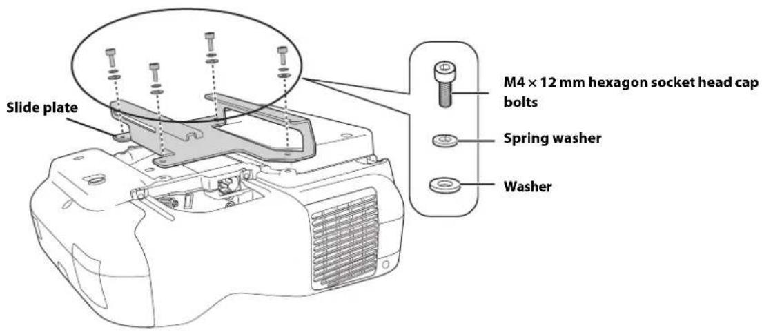
2. Attach the slide plate to the projector.
Attach the slide plate to the projector using the M4 × 12 mm hexagon socket head cap bolts (×4) supplied.
-
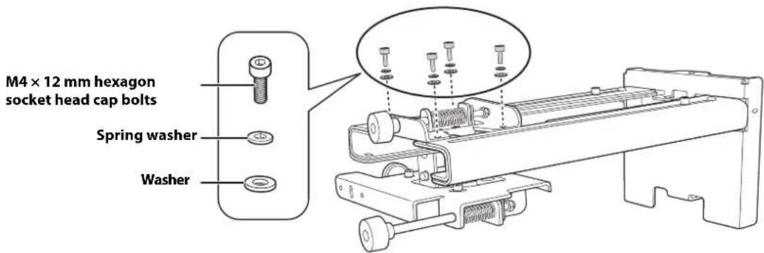
Attach the 3-axis adjustment unit to the wall mount.
-
Decide which position you want to use for installing the 3-axis adjustment unit.
Mount it at the stamp when the image is less than 75 inches (diagonally), or at the stamp when the projected image is 75 inches or more (diagonally).
Less than 75 inches
: 75 inches or more
- Tighten the M4 × 12 mm hexagon socket head cap bolts ( × 4 ) supplied to install the 3-axis adjustment unit.
Bolt installation positions
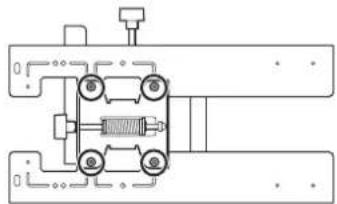
When the diagonal image is less than 75 inches
When the diagonal image is 75 inches or more

Install the wall plate on the wall
-
Determine the template sheet position.
-
From the projection distance table, confirm the screen size (S) and the distance between the projection surface and wall plate bottom holes (c).
- Align the Image Center line (vertical) of the template sheet with the center line (vertical) of the projection surface.
Confirm where the beams or studs are within the wall, and shift the position of the template left or right as necessary.
The position can be shifted horizontally left or right from the center line of the projection surface up to a maximum of 1.77 in. (45 mm.)
- Align the line (horizontal) on the template with the height of (c).
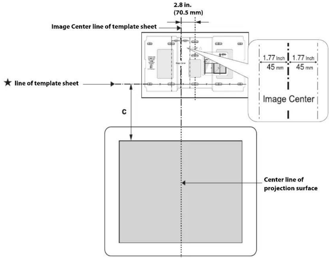
- Attach the template sheet to the wall.
If you need to install a junction box, you can use the cutout areas in the wall plate for the box. The junction box needs to be recessed into the wall if you want to use the wall plate cover, or you can use the wall plate cover extender.
- Determine the position of the wall plate's mounting holes.
Use at least three mounting holes.
- If you are securing the wall plate in four places, drill the holes indicated by A or B in the illustration below.
- If you are securing the wall plate in three places, drill the holes indicated by C in the illustration below.
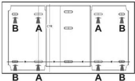
Four mounting holes
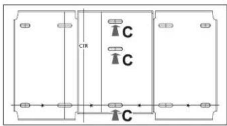
Three mounting holes
Steps 4 to 8 below provide instructions for attaching the wall plate to a concrete wall.
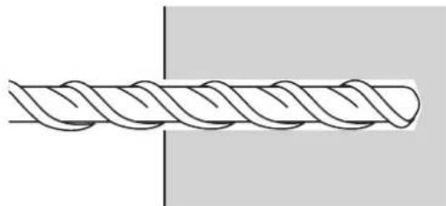
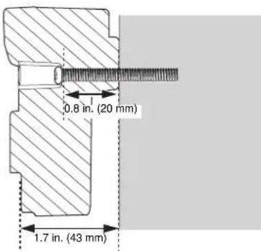
- Drill holes of the following diameters and depths.
| Drill diameter 0.41 in. (10.5 mm) |
| Pilot hole depth 1.8 in. (45 mm) |
| Anchor hole depth 1.6 in. (40 mm) |
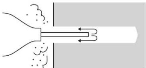
- Remove the template sheet.
- Use a device such as a dust pump to clean out concrete dust from the hole.
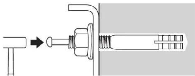
- Position the wall plate on the wall and insert M10 × 60 mm expansion anchors into the holes. Attach the nut and tap it with a hammer until the core touches the top of the anchor.
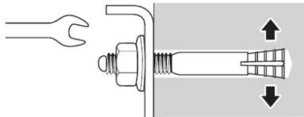
- Tighten the nut with a wrench to secure the wall plate to the wall.

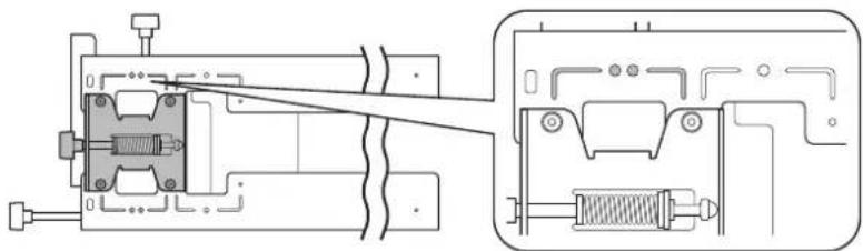
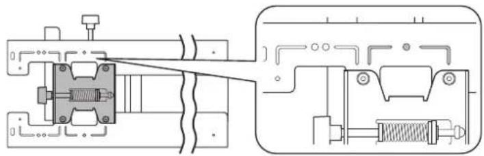
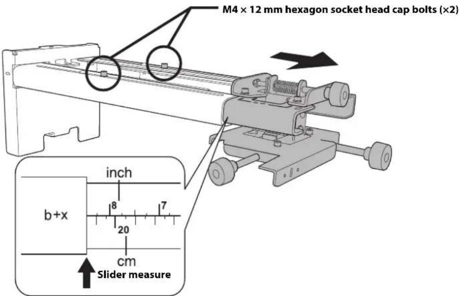
Determine the projection distance and pull out the slider
- Using the tables on pages 21 to 28, check the number for the slider measure (b).
Fig. 2. Loosen the M4 × 12 mm hexagon socket head cap bolts (× 2) , and then pull out the slider on the wall mount.
Align the slider with the measure (b + x) that is equal to the slider measure (b) plus the thickness of the projection screen (x).
For an illustration of how to measure the thickness of the projection screen (x), see page 19.

Route the cables through the wall mount arm
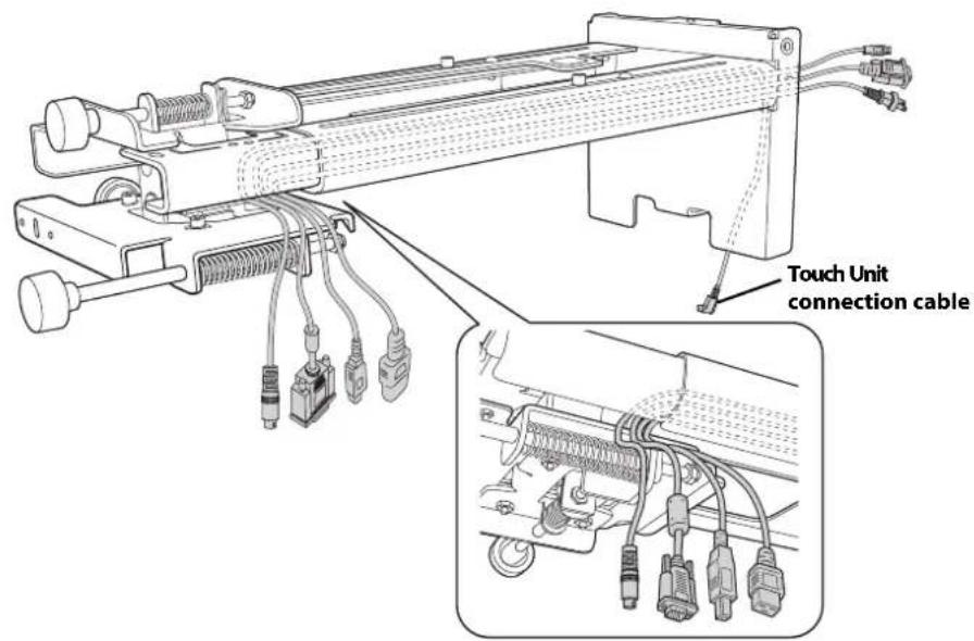

BrightLink 595Wi/595Wi+ and BrightLink Pro 1430Wi: Make sure to route the Touch Unit connection cable through the wall mount arm. Route the Touch Unit connection cable so that the end that connects to the Touch Unit appears from the lower part of the wall mount as shown.

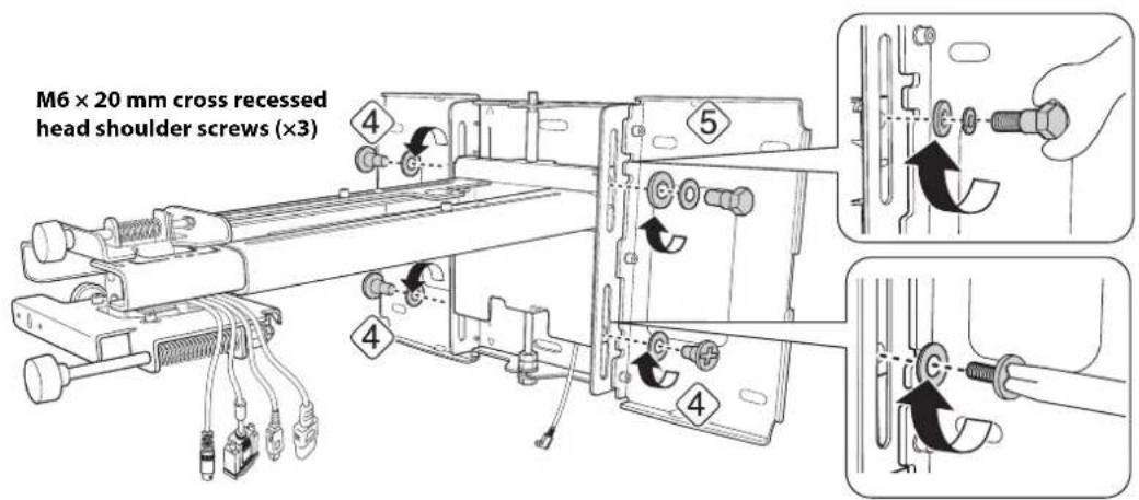
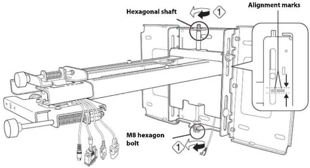
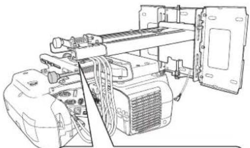
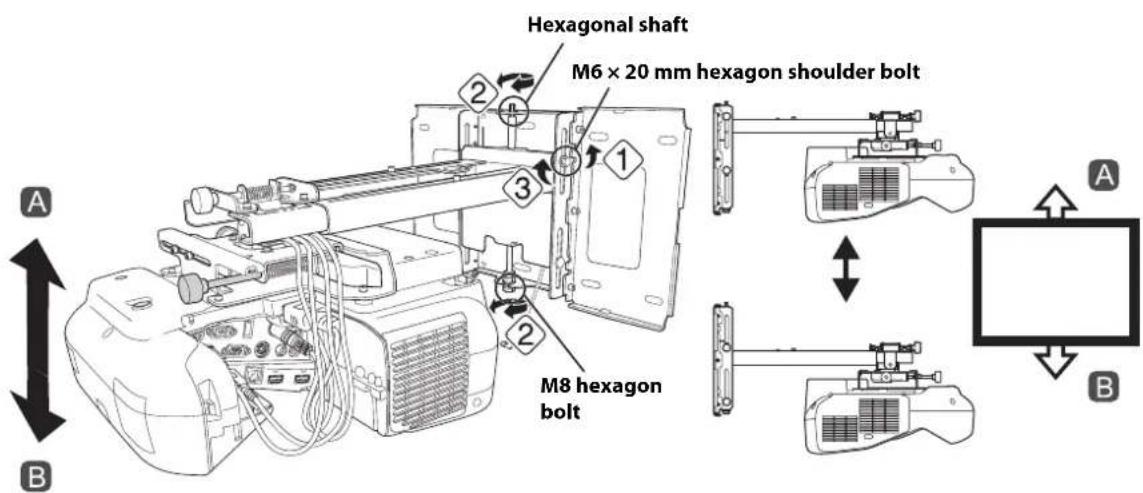
Attach the mount arm to the wall plate
1.Insert the hexagonal shaft into the wall mount ().
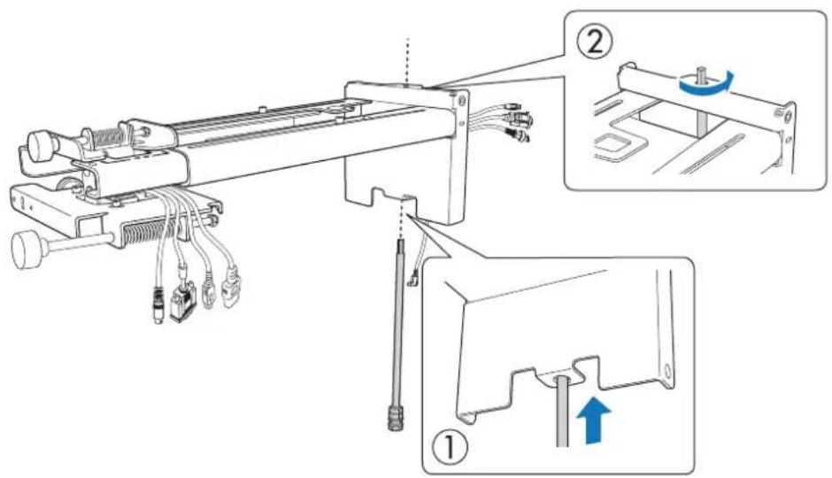
- Insert and turn the hexagonal shaft at the top of the mount arm into the slot on the wall plate (2).
- Insert and turn the M8 hexagon bolt at the bottom of the mount arm into the wall plate (3).
Caution
- Make sure the Touch Unit connection cable is not wired into the wall with the other cables.
- Take care not to trap the cables between the mount arm and wall plate.
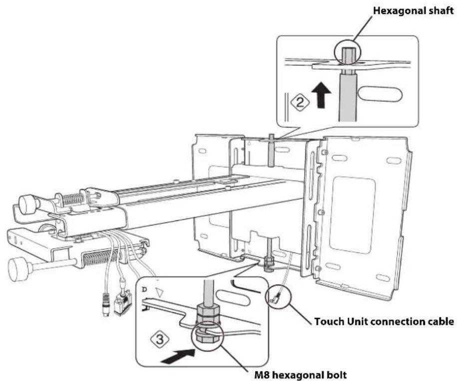
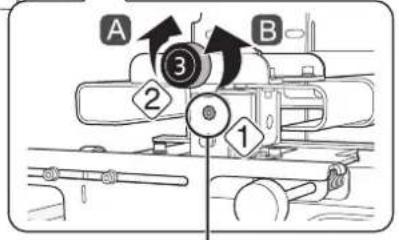
- Secure the mount arm to the wall plate by tightening the supplied M6 × 20mm cross recessed head shoulder screws (× 3) with the No.3 cross-head screwdriver (4). Then, loosely tighten the M6 × 20 mm hexagon shoulder bolt supplied (5)

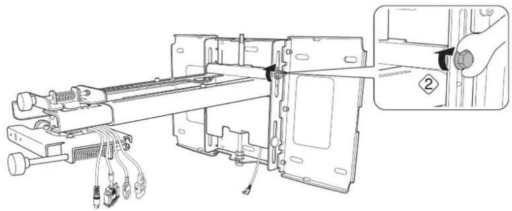
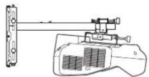
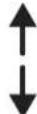
Adjust the vertical slide position of the arm
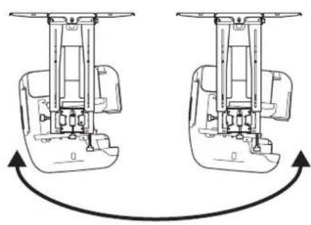
- Adjust the vertical slide with the M8 hexagon bolt at the bottom of the wall mount, or the hexagonal shaft at the top of the wall mount (1). Start by aligning the notch on the arm with the stamp on the wall plate as shown below.
Tightening the M8 hexagon bolt lowers the wall mount, and loosening the bolt raises it. Tightening the hexagonal shaft raises the wall mount, and loosening the shaft lowers it.
- Tighten the M6 × 20 mm hexagon shoulder bolt to secure the wall mount ( ).(2)

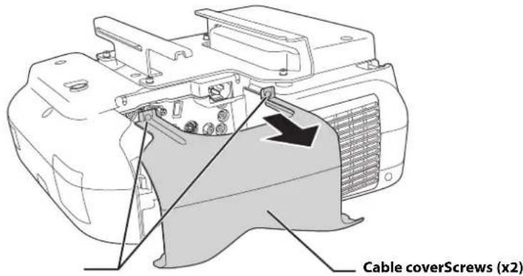
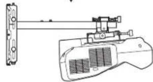
Attach the projector to the wall mount
- Loosen the two screws with a Phillips head screwdriver and remove the cable cover from the projector.
- Insert the slide plate into the wall mount from the interface side of the projector ( )
Align the 3-axis adjustment unit with the slide plate's alignment mark (12)
- Tighten the M4 × 12 mm hexagon socket head cap bolts (×2)().
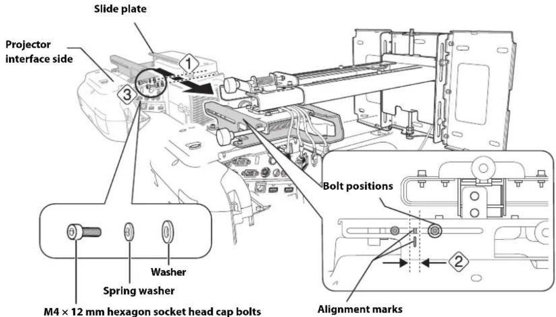

Warning
When installing or adjusting the wall mount, do not use adhesives to prevent the screws from loosening and do not use lubricants or oils on the projector slide plate. This may cause the case to crack and the projector to fall, resulting in personal injury or property damage.

Connect the power cord and other cables to the projector
Connect any necessary cables such as the computer cable, HDMI cable, USB cable, Touch Unit connection cable, Control Pad cables, and power cord to the projector. See your projector's User Guide for detailed connection information.
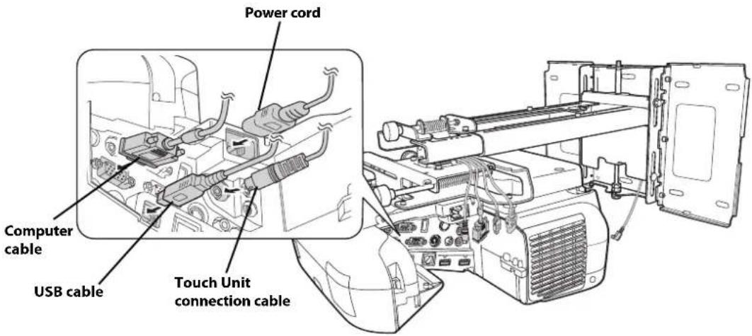

Connect the power cord last.
BrightLink 595Wi/595Wi+: When connecting to the Audio1, Audio2, and Computer1 ports, it is recommended that you connect the cables to the ports in the following order: Audio1, Audio2, and then Computer1.
BrightLink Pro 1420Wi/1430Wi: When connecting to the Audio1, Audio Out, and Computer1 ports, it is recommended that you connect the cables to the ports in the following order: Audio1, Audio Out, and then Computer1.
If you are planning to run the cables inside the wall, make sure you follow all local electrical codes. If you are running the cables outside the wall, use a cable management system to keep the cables from obstructing the image. An optional cable management system is available from Epson (part # ELPCK01).
6 Adjusting the Image
To ensure the best image quality, follow the steps below to adjust the projected image.

Do not make adjustments with the Quick Corner or Keystone functions of the projector. Doing so may result in a reduction in image quality and pen calibration.
Follow these guidelines for setting up the projector:
- Make sure the image is evenly rectangular, without distortion.
Make sure the projector is tilted no more than ± 3^ vertically and horizontally in relation to the projected image.
| Projectile model Remote control column | |
| PowerLite 470/480/570/580 | A |
| BrightLink 475W/480i/485W/575Wi/585Wi/595Wi | |
| BrightLink 575Wi+/585Wi+/595Wi+ | |
| PowerLite 475W/485W/575W/585W | |
| BrightLink Pro 1410Wi/1420Wi/1430Wi B | |

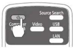
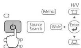
Turn on the projector
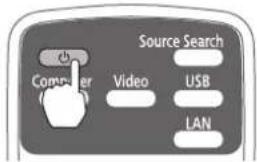
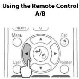
Using the Remote Control A
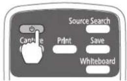
Using the Remote Control B
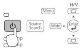
Using the Control Panel

Display the test pattern
- Press the [Help] button.
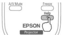
Using the Remote Control A

Using the Remote Control B
Using the Control Panel
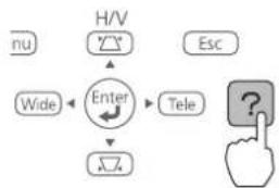
- Press the button on the remote control, or the [Wide] button on the control panel.
The test pattern is displayed.
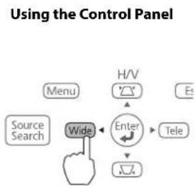
The test pattern contains a guide to help you adjust the displayed image if your screen's aspect ratio is the same as the projector's native aspect ratio.

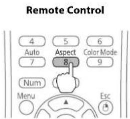
Change the aspect ratio if necessary
Each time you press the [Aspect] button on the remote control, the aspect name is displayed on the screen and the aspect ratio changes. You will need to re-display the test pattern after changing the aspect ratio.
Change the setting according to the signal for the connected equipment.
You may need to project content from a connected device in order to change the aspect ratio.
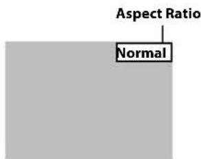
Alternatively, set the aspect ratio from the Signal menu - Aspect. Following is a list of available aspect settings:
BrightLink 480i and PowerLite 570/580
- Auto: Automatically sets the aspect ratio according to the input signal and the Resolution setting (available only for HDMI image sources).
- Normal: Displays images using the full projection area and maintains the aspect ratio of the image. Choose this setting or Auto to automatically resize the image and make the best use of the display area.
4:3: Displays images using the full projection area at 4:3 aspect ratio. - 16:9: Converts the aspect ratio of the image to 16:9. 4:3 ratio images are elongated horizontally to fit.
BrightLink Pro 1410Wi/1420Wi/1430Wi, BrightLink 575Wi/575Wi+/585Wi/585Wi+/595Wi/595Wi+, and PowerLite 575W/585W
- Auto: Automatically sets the aspect ratio according to the input signal and the Resolution setting (available only for HDMI image sources).
- Normal: Displays images using the full projection area and maintains the aspect ratio of the image. Choose this setting or Auto to automatically resize the image and make the best use of the display area.
- 16:9: Converts the aspect ratio of the image to 16:9. 4:3 ratio images are elongated horizontally to fit.
- Full: Displays images using the full width of the projection area, but does not retain the aspect ratio. 4:3 ratio images are elongated horizontally.
- Zoom: Displays images using the full width of the projection area and maintains the aspect ratio of the image. The image may be cut off on the top and bottom depending on its aspect ratio.
- Native: Displays images as is (aspect ratio and resolution are maintained). Black bands may appear or images may be cut off, depending on the resolution.
一 Projector User's Guide: Signal Menu

Adjust the focus
- Slide the air filter cover switch () to open the air filter cover().
2.Use the focus lever to adjust the focus ( ).3
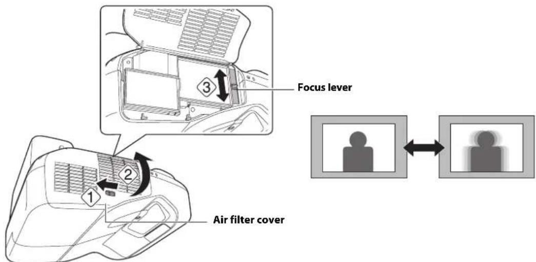
- After you finish making the adjustment, close the air filter cover.

Use the adjustment knob on the left side to adjust the horizontal roll

Repeat steps 5 to 10 as necessary. For each step, you may need to re-display the test pattern as shown in step 2.
- Loosen the screw () to unlock the adjustment knob.

-
Turn the orange knob () adjust the horizontal roll ( ).
-
After you finish making all of the adjustments in steps
to 10, tighten the screw you loosened in

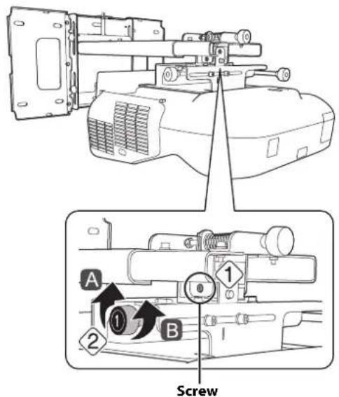
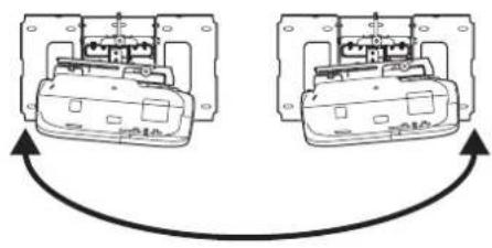
Use the adjustment knob on the right side to adjust the horizontal rotation
- Loosen the screws (x2) to unlock the adjustment knob().
- Turn the dark blue knob () adjust the horizontal rotation ( ).

- After you finish making all of the adjustments in steps
5 to 10, tighten the screws (x2) you
loosened in 1

Use the adjustment knob on the top to adjust the vertical tilt
- Loosen the screw () to unlock the adjustment knob.
Screw

A
B
- Turn the light blue knob () adjust the vertical tilt ( ).

- After you finish making all of the adjustments in steps
5 to 10, tighten the screw you loosened in


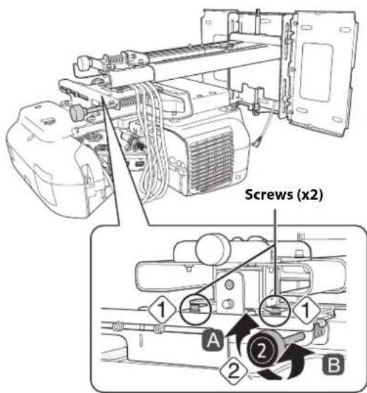
Adjust the horizontal slide
- Loosen the M4 × 12 mm hexagon socket head cap bolts (×2), and then adjust the slider for the slide plate.
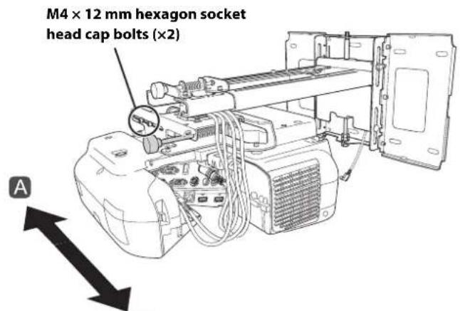
B
- After you finish making all of the adjustments in steps 5 to 10, tighten the M4 × 12 mm hexagon socket head cap bolts (×2).

Adjust the forward/backward slide
- Loosen the M4 × 12 mm hexagon socket head cap bolts (× 2) , and then adjust the slider for the wall mount.
- After you finish making all of the adjustments in steps 5 to 10, tighten the M4 × 12 mm hexagon socket head cap bolts (×2).

Adjust the vertical slide
- Loosen the M6 × 20 mm hexagon shoulder bolt ( ).
- Adjust the vertical slide with the M8 hexagon bolt at the bottom of the wall mount, or the hexagonal shaft at the top of the wall mount (12)
Tightening the M8 hexagon bolt lowers the wall mount, and loosening the bolt raises it. Tightening the hexagonal shaft raises the wall mount, and loosening the shaft lowers it.
- Tighten the M6 × 20 mm hexagon shoulder bolt you loosened in the first step ( ). 3

Turn off the display of the test pattern
Press the [Esc] button on the remote control or control panel to turn off the test pattern.

Warning
Tighten all screws firmly. Otherwise, the projector or wall mount may fall and cause personal injury or property damage.
7 Attaching the Covers

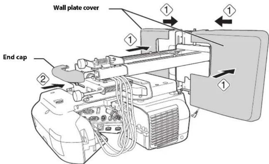
Attach the wall plate cover and end cap
If you need to use a security cable, make sure you attach it before installing the wall plate cover. See page 66 for instructions.

You can use the wall plate cover extender (if included) to increase the depth of the wall plate cover and accommodate larger cables and plugs.
To add the extender, clip each half of the extender to the wall plate cover pieces before you attach the cover to the mount.
Adding the wall plate cover extender limits the minimum size of the projected image. See page 20 for more information.
- Attach the wall plate cover (1). Snap the tabs on the cover into the holes on the wall plate. (If you need to remove the cover, press the tabs.)

Depending on how the cables are wired, you may need to cut out parts of the wall plate cover to allow the cables to be passed through it.
When cutting the thin section of the wall plate cover and passing the cables through, make sure you perform deburring to smooth off any sharp edges to prevent damaging the cables.
Also, make sure you operate the cutter safely.
- Place the end cap with the concave portion facing up ( ).

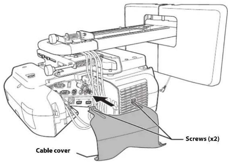
Attach the cable cover to the projector
Attach the cable cover and use a Phillips head screwdriver to tighten the screws (x2) and secure the cable cover.
Caution
Only a specialist should remove or reinstall the projector, including for maintenance and repairs. Refer to your projector's User's Guide for instructions on maintenance and repairs.
Warning
- Never loosen the bolts and nuts after installation. If you find any loose screws, tighten them firmly. Otherwise, the projector or wall mount may fall and cause personal injury or property damage.
- Do not hang on the wall mount or hang a heavy object on the wall mount. If the projector or wall mount falls, it could cause personal injury or property damage.
The following procedures must have been completed before installing the Touch Unit:
- Installing the projector (see page 30)
- Adjusting the projected image (see page 41)
- Calibrating the interactive pen(s)
Refer to your projector User's Guide or Start Here folder for detailed instructions.

There are magnets built in to the back of the Touch Unit. Typically, the Touch Unit should be installed by attaching the magnets to the screen or whiteboard.
□If the magnets cannot be attached, use commercially available M4 screws (×3).
Install the Touch Unit on a flat, smooth, unwarped surface that is the same level surface as the screen surface. If there is unevenness on the screen surface of more than 0.2 inches (5 mm) in any direction, your fingers may not be detected and finger touch operations may not be performed correctly.
Follow the steps below to install the Touch Unit and connect to the projector. Some menus may differ slightly from the illustrations, but the installation instructions are the same.

Caution
The Touch Unit should only be connected to the BrightLink 595Wi/595Wi+ or BrightLink Pro 1430Wi models. Do not connect the Touch Unit to any other projectors or devices.

Turn on the projector
Using the Remote Control BrightLink 595Wi/595Wi+
Using the Remote Control BrightLink Pro 1430Wi
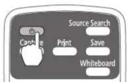
Using the Control Panel

Display the installation pattern
- Select Easy Interactive Function from the Extended menu.
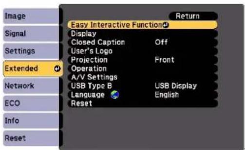
2. Select Touch Unit Setup.
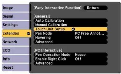
3. Select Installation Pattern.
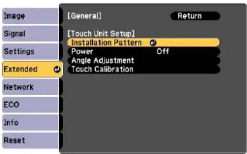
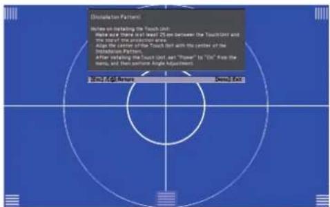
The Installation pattern is displayed on the projected image.

Remove the markers
- Loosen the screw at the bottom of the dial cover.
- Slide the dial cover down to remove it.
- Remove the two markers from inside the Touch Unit.
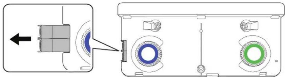
Use the markers to perform the angle adjustment (p. 53) after installing the Touch Unit.

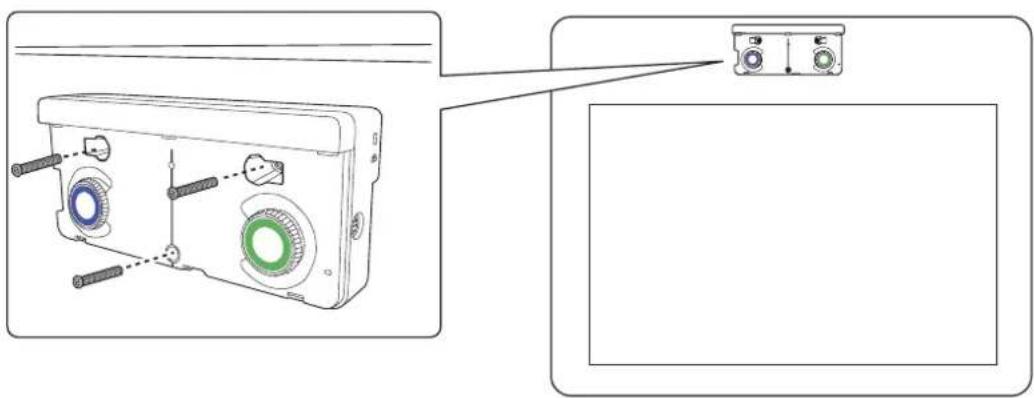
Determine the installation position for the Touch Unit
Mark the following installation positions:
- (1): The center line of the installation pattern; align it with the center line of the Touch Unit (3).
- (2): 1 inch (25 mm) from the top edge of the projected image; align with the bottom edge of the Touch Unit.
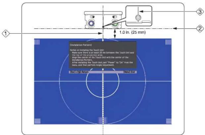

The Touch Unit must be installed above the image area.

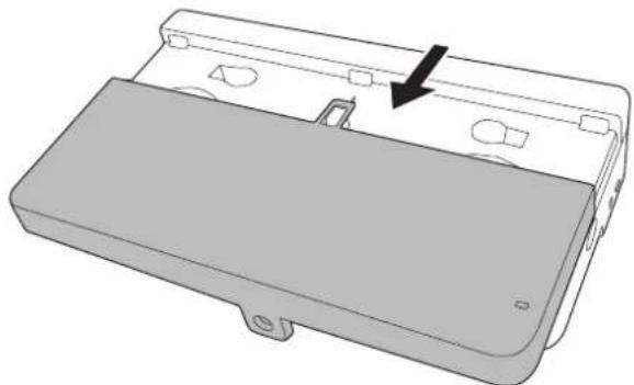
Install the Touch Unit
- For magnetic screens, place the back of the Touch Unit on the screen surface to secure it.

Caution
When installing the Touch Unit on a magnetic surface, be careful not to trap your fingers or any other part of your body between the magnets and the installation surface.
- For non-magnetic screens, secure the Touch Unit with three (3) M4 screws (not included).

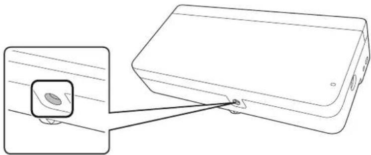
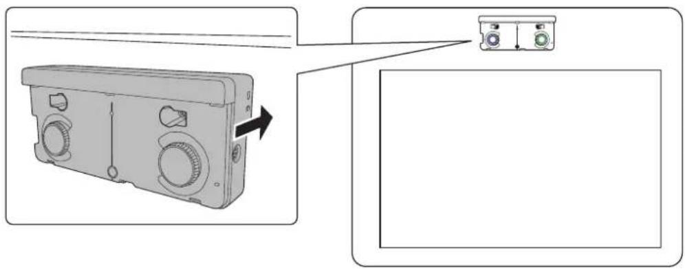
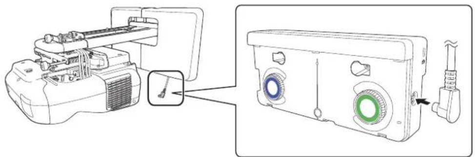
Connect the cable
Connect the Touch Unit connection cable that is connected to the projector to the port on the Touch Unit.

Adjust the angle
Adjust the angle of the laser light coming from the Touch Unit so that the Touch Unit can detect the position of your fingers.

Make sure to calibrate the interactive pen(s) before adjusting the angle. Press the User button on the remote control and select Yes to perform an auto-calibration. Refer to the projector's User's Guide for detailed instructions on calibrating the pen(s).
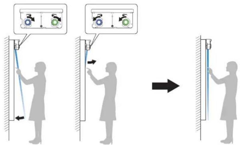
- Select Easy Interactive Function from the Extended menu.

2. Select Touch Unit Setup.

3. Select Power and set to On.
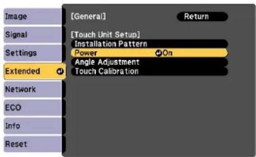
The Touch Unit power turns on and the indicator light turns blue.
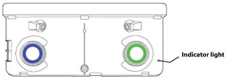
Warning
Do not look into the projector's projection window or the Touch Unit's laser diffusion ports (located on the back of the Touch Unit); this could cause injury to eyesight.

When Power is set to On, the Touch Unit automatically powers up the next time the projector is turned on.
4. Select Angle Adjustment.
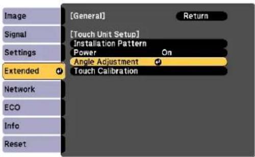
The Angle Adjustment screen is displayed.
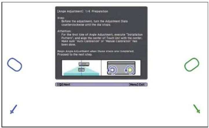
- Turn the adjustment dials on the Touch Unit counterclockwise until you hear a click. Then, press the button on the remote control.
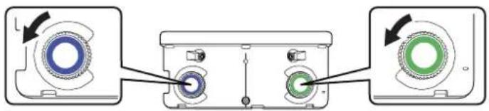

When adjusting the dials, make sure to stop turning when you hear the click.
- Attach the two markers you removed from the Touch Unit to the marker positions shown on the
projected screen().

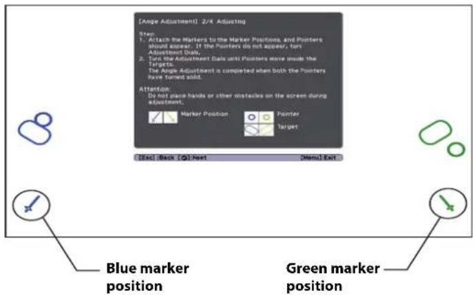
Match the positions so that the crosses (1) overlap with the points (2) on the marker positions
( ). Move the marker over the projected cross until the lines of the cross align with the lines on the marker.
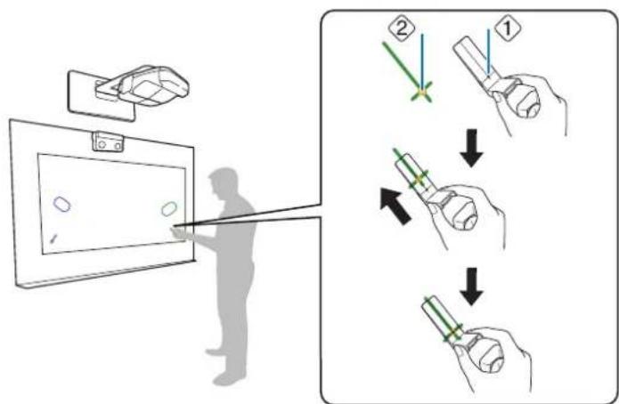
When pointers ()

with the same color (blue and green) as the marker positions are
displayed on the left and right of the projection screen, attach the markers to the projection screen as follows:
- For magnetic screens: Place the bottom of the markers onto the screen.
- For non-magnetic screens: Use the supplied tape to secure the markers. Attach the tape so that each end of the marker is secure on the screen.
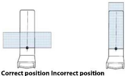

Do not place anything other than the markers near the projected image during angle adjustment. If other objects are on the projected image, angle adjustment may not be performed correctly.
- Turn the adjustment dials on the Touch Unit to move the pointers (O) (O) so that they move
inside of the target () of the same color (blue and green) on either side.
Turning an adjustment dial clockwise moves the pointer diagonally up towards the center of the projected image.
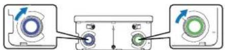
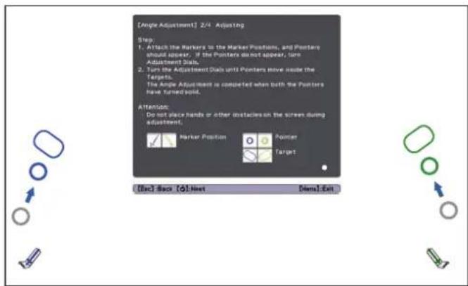
Turning an adjustment dial counterclockwise moves the pointer diagonally down away from the center of the projected image.
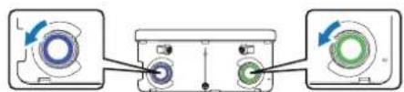
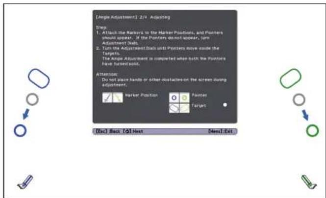
When the pointers are inside the target, the colors become solid ( ).

□If a dial makes a clicking sound, the pointer will not move any further.
□When turning the dials, make sure shadows from your arm and body do not cover the markers.
- When the pointers on the left and right become solid colors ( ), press the button on the remote control. The following screen is displayed:
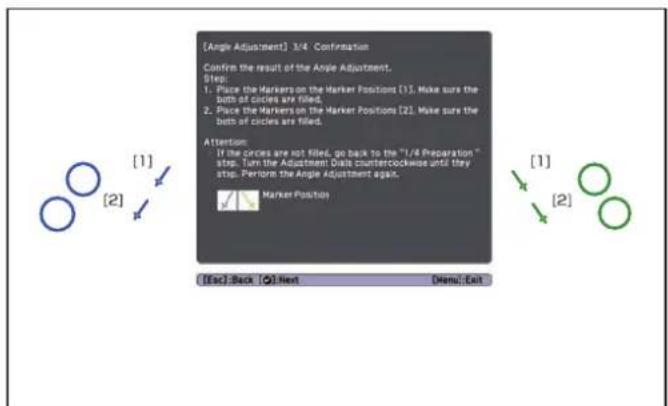
- Place the markers at the top marker positions [1]. When angle adjustment is performed correctly, the upper pointers become solid colors ( ) ( ). If the upper pointers do not become solid colors
()(), start again from step 4.
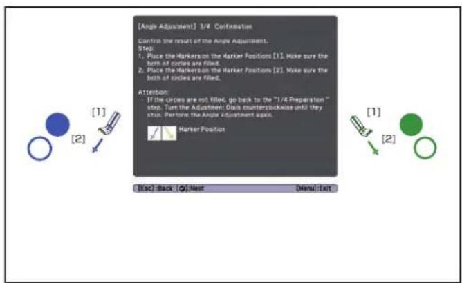
- Place the markers at the bottom marker positions [2]. When angle adjustment is performed correctly, the bottom pointers become solid colors ( ) ( ). If the bottom pointers do not become solid colors ( ) ( ), start again from step 4.
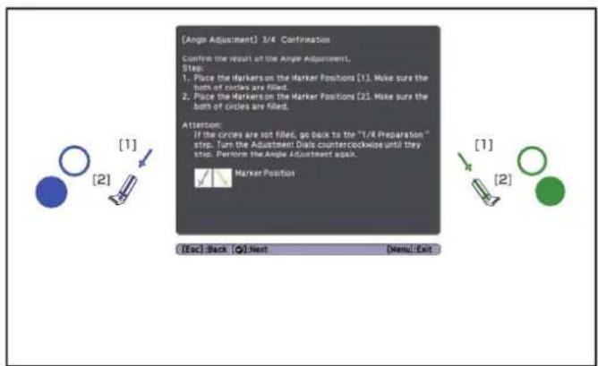
- When you have finished checking the marker positions, remove the markers and press the button on the remote control. The following confirmation screen is displayed:

- Trace the dots with your finger as shown. When angle adjustment is performed correctly, the traced dots disappear.
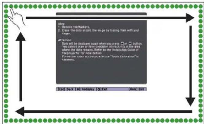

Finger touch operations may not function correctly if you are wearing bandages, artificial nails, nail polish, or anything else that may obstruct your fingers.
When all of the dots have disappeared, press the button on the remote control and then go to step 13.
If any dots remain (as shown below), do the following:
- Remove any obstacles from around the projected screen. When you are finished, press the or button on the remote control and repeat step 12.
- If the dots still remain after removing obstacles, turn the adjustment dials about a quarter turn counterclockwise. Next, press the or button on the remote control and repeat step 12.
- If the dots still remain or there are obstacles that cannot be removed, such as whiteboard trays or frames, go to step 13.
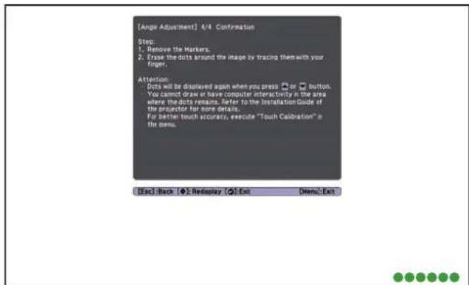
- If there is an obstacle that cannot be removed, such as a whiteboard tray or frame, remove the tape from the back of the supplied infrared deflectors and stick them to the screen so that the laser is not reflected by the obstacle.
Make sure to stick the deflectors between the dots and the obstacle and adjust the number of deflectors according to the number of dots.
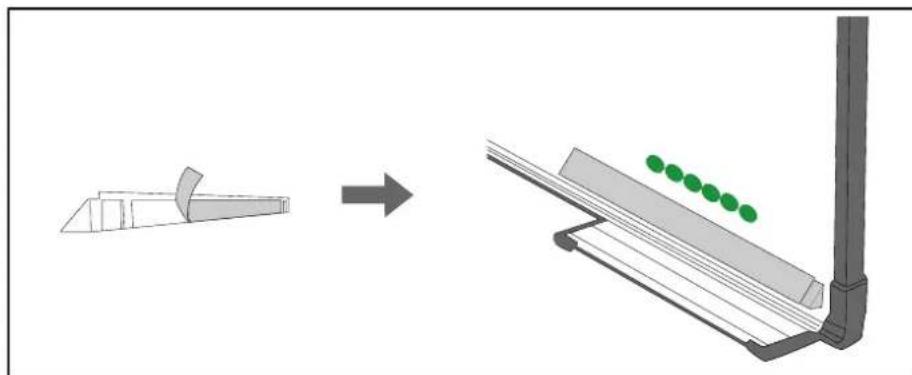

□Do not remove an infrared deflector once it has been stuck in place.
Do not stick tape or place anything on the infrared deflectors. The deflectors will not function properly if anything is placed on them.
After placing the infrared deflectors, press the or button on the remote control, and then repeat step 12.
If the dots do not disappear even after attaching the infrared deflectors, turn the adjustment dials about a quarter turn counterclockwise. Next, press the or button on the remote control, and then repeat step 12 again.
If the dots do not disappear even after performing the above procedures, contact Epson.
- Perform touch calibration by pressing Menu on the remote control. On the Extended menu, select Easy Interactive Function, then Touch Unit Setup. Select Touch Calibration and follow the instructions.

Store the markers and attach labels
- Store the markers inside the Touch Unit.
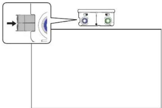
- Attach the labels to the tabs on either side of the Touch Unit. Match the centers of the labels with the tabs on the Touch Unit.
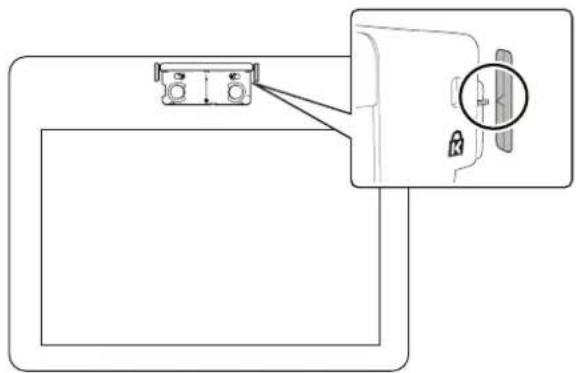

If the Touch Unit moves out of position, use the position of the labels to determine where to reposition the Touch Unit.

Attach cover
Attach the dial cover. Make sure to tighten the screw at the bottom of the cover.
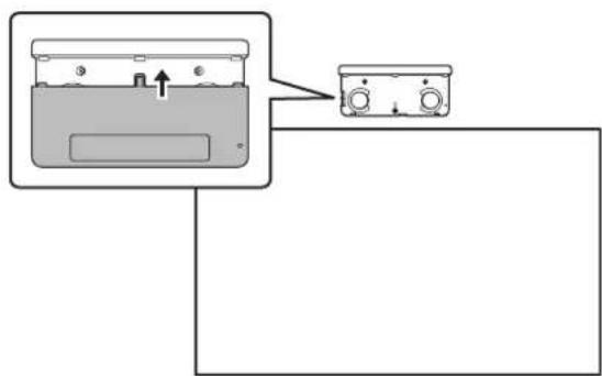
You must have completed the steps in "Installing the Projector" on page 30 before installing the Control Pad.
Follow the steps below to install the Control Pad and connect to the projector.
Caution
The Control Pad should only be connected to the BrightLink Pro 1410Wi/1420Wi/1430Wi. Do not connect the Control Pad to any other projectors.
Check the installation location
The Control Pad must be installed in the area specified in the diagram below.
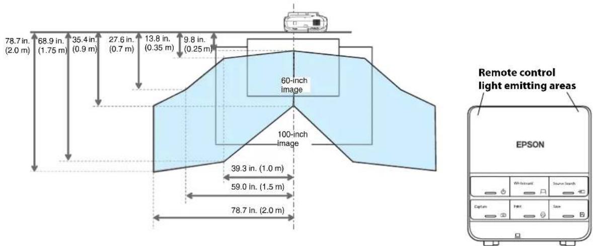

Make sure there is enough space surrounding the Control Pad. Because the top panel opens from the left, there must be additional space to the left of the Control Pad.
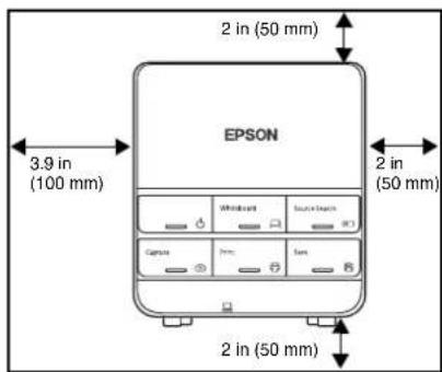
1 Remove the cable cover

2 Attach the Control Pad
Attach the Control Pad with commercially available M4 × 20 mm screws (×4).
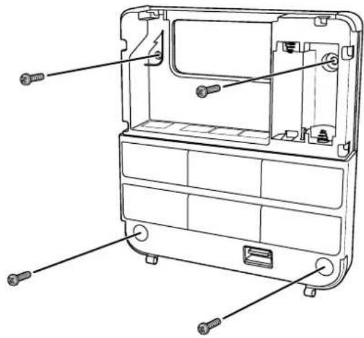
Warning
Make sure the screws are not angled.
Make sure the Control Pad is firmly attached.
Do not attach the Control Pad with double-side tape or magnets.

Check that the Control Pad is operating correctly before attaching it with the screws.
When installing the Control Pad on a table, attach the supplied rubber feet (x4) to the base of the Control Pad to prevent it from slipping.
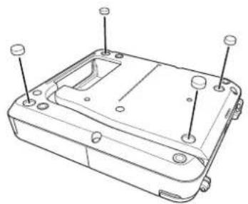

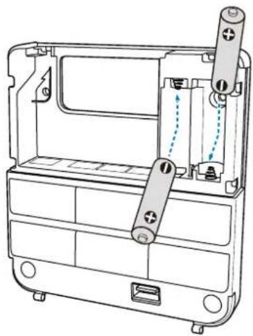

Caution
Before handling the batteries, read the safety instructions in your projector's User's Guide.

Use two AA manganese or alkaline (recommended) batteries. Do not use any other type of battery. Rechargeable batteries cannot be used.
In order to use the projector to power the Control Pad, connect the optional Remote control cable set (model ELPKC28, part number V12H005C28) to the projector's Remote port and the Control Pad's Remote port. Do not install batteries.

Connect the projector cables to the Control Pad
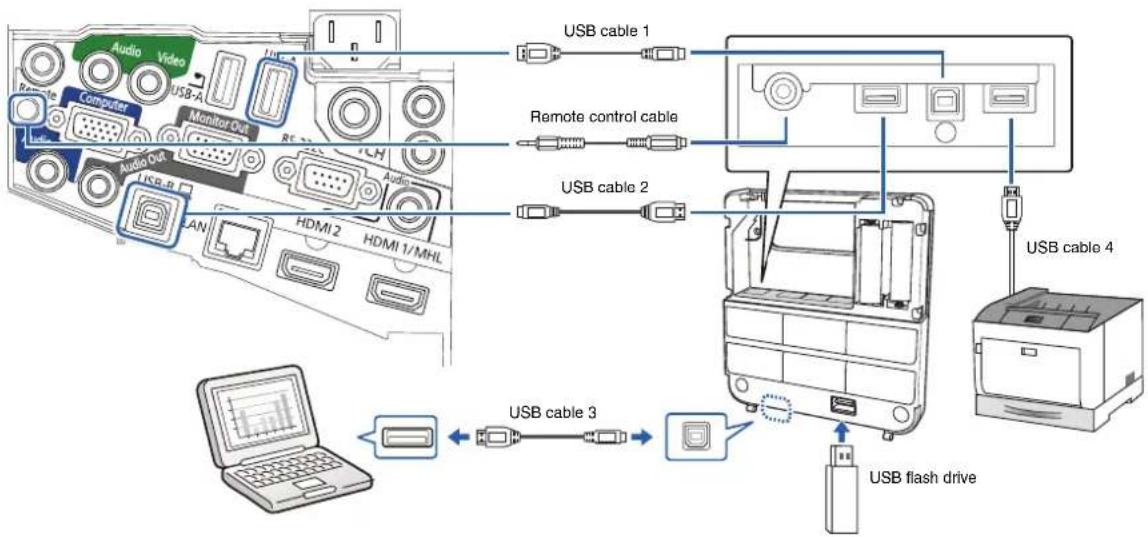
To perform the functions listed below, you will need to connect the appropriate cables:
| Projectile function Required cables | |
| Projecting images from a USB flash drive | USB cable 1 |
| Saving data to a USB flash drive | |
| Supplying power from the projector Remote control | cable set (model ELPKC28; part number V12H005C28) |
| Projecting computer images with USB Display or performing mouse functions using the Easy Interactive Function | USB cable 2 USB cable 3 |
| Printing a projected image USB cable 1 | USB cable 4 |

Attach the port protection stickers
Cover the Control Pad ports that are not being used.

Attach the cable cover
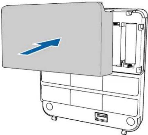
10 Appendix
Using the Easy Interactive Function
After you install your BrightLink model (and the Touch Unit, if applicable), you need to perform calibration to align the positions of the cursor and your interactive pen(s) (and finger, if the Touch Unit is installed). See the projector's online User's Guide or Start Here folder for detailed instructions.
In order to use the Easy Interactive Tools software, you must first install the software on the computer. OS X users also need to install a driver that enables pen or finger touch interactivity to work. Both software programs are included with the BrightLink projector.
For details, see the online User's Guide or visit:
U.S.: epson.com/support/brightlinkdownloads
Canada:epson.ca/support/brightlinkdownloads
Latin America: global.latin.epson.com/Soporte (website available only in Spanish)
Attaching a Security Cable
If the projector is to be installed in a room where it will be left unattended, you can use a commercially available theft-prevention wire lock to secure the projector to a post or other object to prevent someone from taking it.
Pass the wire for the theft-prevention wire lock through the security cable installation point.
For details on how to lock the wire lock, refer to the User's Guide supplied with the wire lock.
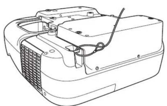
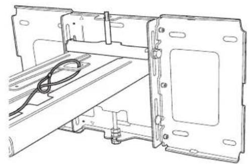
Make sure you leave the remote control, batteries, CDs, interactive pen(s), pen batteries, pen tray, and battery charger in the room with the projector. If your projector came with a product-specific installation guide or an installation leave-behind list, use that list instead of this one. The accessories included with the projector vary by model and region.
1Retirez le cache-cables
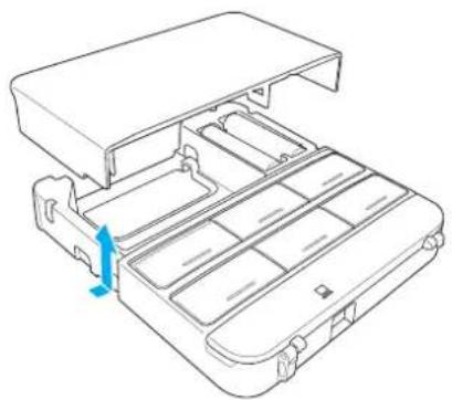
Canada:epson.ca/support/brightlinkdownloads
- Safety Instructions
- Explanation of Symbols
- Safety Precautions for Installation
- Warning
- Caution
- Installation Location
- Package Contents
- Specifications
- Connecting Devices
- Positioning the Projector
- Installing the Projector
- Adjusting the Image
- Attaching the Covers
- Installing the Touch Unit
- Installing the Control Pad
- Appendix
- Wall Mount
- Touch Unit
- Control Pad
- Wall plate
- Vertical slide adjustment range
- Horizontal slide adjustment range
- Forward/backward slide adjustment range
- Arm slide adjustment range
- Adjustment from 3-axis adjustment unit installation position
- External dimensions and weight
- Attached labels
- Cable routing holes
- For Interactive Use
- Connecting the Control Pad
- Installation worksheet for projecting on a pre-installed wall-mounted board
- Installation worksheet for projecting on a plain wall
- Diagonal image size and mounting position
- Distance from projection surface to wall plate
- Installation measurement tables
- Disassemble the parts
- Assemble the parts
- Assemble the wall plate.
- Attach the slide plate to the projector.
- Bolt installation positions
- Install the wall plate on the wall
- Determine the projection distance and pull out the slider
- Route the cables through the wall mount arm
- Attach the mount arm to the wall plate
- Adjust the vertical slide position of the arm
- Attach the projector to the wall mount
- Connect the power cord and other cables to the projector
- Connect the power cord last.
- Turn on the projector
- Display the test pattern
- Change the aspect ratio if necessary
- BrightLink 480i and PowerLite 570/580
- BrightLink Pro 1410Wi/1420Wi/1430Wi, BrightLink 575Wi/575Wi+/585Wi/585Wi+/595Wi/595Wi+, and PowerLite 575W/585W
- 一 Projector User's Guide: Signal Menu
- Adjust the focus
- Use the adjustment knob on the left side to adjust the horizontal roll
- Use the adjustment knob on the right side to adjust the horizontal rotation
- Use the adjustment knob on the top to adjust the vertical tilt
- Adjust the horizontal slide
- Adjust the forward/backward slide
- Adjust the vertical slide
- Turn off the display of the test pattern
- Attach the wall plate cover and end cap
- Attach the cable cover to the projector
- Display the installation pattern
- Select Touch Unit Setup.
- Select Installation Pattern.
- Remove the markers
- Determine the installation position for the Touch Unit
- Install the Touch Unit
- Connect the cable
- Adjust the angle
- Select Power and set to On.
- Select Angle Adjustment.
- Store the markers and attach labels
- Attach cover
- Check the installation location
- Remove the cable cover
- Attach the Control Pad
- Connect the projector cables to the Control Pad
- Attach the port protection stickers
- Attach the cable cover
- Using the Easy Interactive Function
- Attaching a Security Cable
- 1Retirez le cache-cables
Brand : EPSON
Model : V12H777020
Category : Projector Accessory