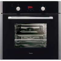
ME 605 TC - Oven CATA - Free user manual and instructions
Find the device manual for free ME 605 TC CATA in PDF.



| Product type | Built-in oven |
| Brand | CATA |
| Model | ME 605 TC |
| Useful volume | 59 liters |
| Internal dimensions (W x H x D) | 440 x 340 x 390 mm |
| Power supply voltage | 220-240 V ~ 50 Hz |
| Grill element power | 1.35 kW |
| Bottom element power | 1.30 kW |
| Top element power | 0.90 kW |
| Fan element power | 2.30 kW |
| Cooking functions | Light, convection, top element, bottom element, circular + fan, grill, maxi-grill, grill + fan, defrost |
| Temperature range | 50 °C to 250 °C |
| Electronic timer | Independent alarm, semi-automatic and automatic cooking (duration and end of cooking) |
| Cleaning system | AquaSmart (steam cleaning) |
| Interior lighting | 15-25 W bulb, type E-14, resistant to 300 °C |
| Door | Removable for easy cleaning |
| Door glass | Removable (several types depending on version) |
| Included accessories | Grill, drip tray, side guides |
| Installation | Standard 600 mm built-in, requires 13 A bipolar switch with 3 mm contact |
| Power cable | 3 x 1.5 mm² type H07RN-F |
| Appliance class | Class I (mandatory earthing) |
Frequently Asked Questions - ME 605 TC CATA
User questions about ME 605 TC CATA
0 question about this device. Answer the ones you know or ask your own.
Ask a new question about this device
Download the instructions for your Oven in PDF format for free! Find your manual ME 605 TC - CATA and take your electronic device back in hand. On this page are published all the documents necessary for the use of your device. ME 605 TC by CATA.
USER MANUAL ME 605 TC CATA
natural_image
Exterior view of a modern stainless steel oven with digital display and control knobs (no text or symbols on main body)ES
Operating and maintenance instructions for built-in ovens
IT
natural_image
Three technical line drawings showing a door opening, a flat panel with a handle, and a vent with a lid (no text or symbols)natural_image
Simple line drawing of a hand placing a small object into a container (no text or symbols)chemical
Two molecular orbital diagrams showing electron density distributions with spin arrows and charge carrierschemical
Simple molecular structure diagram showing two circular arrangements with substituents and electron density indicatorschemical
Simple molecular structure diagram showing two configurations with central atom and surrounding atomsPIEZAS ESMALTADAS VITRIFICADAS
Tipo de puerta C
natural_image
Technical line drawing of a mechanical assembly with layered components (no text or symbols)ADVERTENCIA
natural_image
Line drawing of an open microwave oven with doors open (no text or symbols)Reja tipo 2
natural_image
Technical line drawing of an open oven or rack unit with internal compartments and mounting holes (no text or symbols)natural_image
Technical illustration showing a battery connected to a motor panel and its three-wheeled cable assembly (no text or symbols present)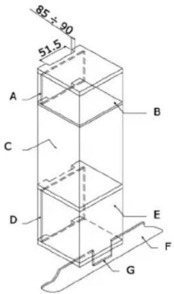
CONEXIÓN ELÉCTRICA
natural_image
Technical line drawing of a mechanical bracket assembly (no text or symbols)natural_image
Line drawing of a hand opening a gridded oven (no text or symbols)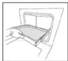
natural_image
Line drawing of a hand opening a rectangular tray (no text or symbols)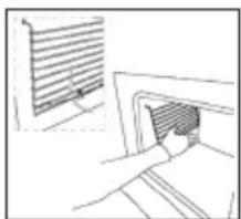
natural_image
Line drawing of a hand inserting a component into a wall, with a window on the left (no text or symbols)natural_image
Simple line drawing of a hand inserting a capsule into a rectangular frame (no text or symbols)chemical
Two molecular orbital diagrams showing electron density distributions around a central atomchemical
Two molecular orbital diagrams showing electron density distributions around a central atomchemical
Two molecular orbital diagrams showing electron density distributions with labeled orbitals and bondingEMAILIERTE TEILE
Tür vom Typ B1 / B2
Tür vom Typ C
natural_image
Technical line drawing of a mechanical assembly with layered components and a handle (no text or symbols)WICHTIGER HINWEIS
natural_image
Line drawing of an open oven with doors open, showing internal compartments and ventilation grilles (no text or symbols)Gitter vom Typ 2
natural_image
Technical line drawing of an open oven or rack unit with internal compartments and mounting holes (no text or symbols)natural_image
Diagram showing a battery connected to a motor and its three-wheeled cable assembly (no text or labels)natural_image
Technical line drawing of a mechanical component with mounting holes and internal channels (no text or symbols)natural_image
Three technical line drawings showing a door opening, a side view of a vent, and a slatted panel (no text or symbols)natural_image
Simple line drawing of a hand inserting a plug into a container (no text or symbols)chemical
Two molecular orbital diagrams showing electron density distributions around a central atomchemical
Two molecular diagrams showing electron density distributions with central atom and surrounding atomschemical
Two simple molecular diagrams showing electron configuration with positive and negative chargesnatural_image
Technical line drawing of a mechanical assembly with two views (top and side), showing components like gears and base plates (no text or symbols)Type de porte C
natural_image
Technical line drawing of a mechanical assembly or folding device (no text or symbols)AVERTISSEMENT
natural_image
Line drawing of an open microwave oven with doors open (no text or symbols)Grille type 2
natural_image
Technical line drawing of an open oven or rack unit with internal compartments and doorways (no text or symbols)IINSTRUCTIONS POUR L'INSTALLATION
natural_image
Diagram showing a battery connected to a motor panel and its cable assembly (no text or symbols present)BRANCHEMENT ÉLECTRIQUE
natural_image
Technical line drawing of a mechanical bracket or housing component (no text or symbols)ENTRETIEN ET REMPLACEMENT DES REVÊTEMENTS CATALITIQUES
Thank you for choosing one of our products. We hope this household appliance provides you with the best service. Therefore, we suggest you read the instructions and suggestions contained in this manual carefully in order to use our products correctly.
The specifications plate for this oven is available on this appliance. This plate, visible by opening the door, displays all the necessary identification information for this appliance for ordering replacement parts.
GENERAL INFORMATION
Please read this manual carefully before using the appliance. It is important that all the control functions are understood before beginning to cook with this appliance.
Heed the advice and warnings included under the title "IMPORTANT – Safety advice and instructions".
- This appliance has been designed for private domestic use and can be integrated into standard kitchen furnishings or similar.
- In order to use in caravan-type vehicles, indications included in the Installation Instructions should be borne in mind.
- Use of this appliance for any other purpose or in any other environment without the manufacturer's express agreement will invalidate any guarantee or liability.
- This new appliance is guaranteed against mechanical defects, subject to certain exclusions indicated in the Manufacturer's Terms and Conditions of the Guarantee.
• The above does not affect your statutory rights.
Ensure that all protective packaging and covering has been removed before using this appliance.
To collaborate in protecting the environment, separate the packaging materials into the different types and dispose of them according to local waste disposal regulations.
The packaging is designed so as not to harm the environment; it can be recovered or recycled as it is an ecological product. By recycling the packaging, you will contribute to saving raw materials and reducing the volume of industrial and domestic waste.
Any additional information on waste disposal may be requested from your local environmental agency.
When used for the first time, a slight smell from the protective covering or damp may be noticeable, which will disappear after a short time.
The symbol on the product or its packaging indicates that this product cannot be treated as normal household waste. This product must be handed over to an electric and electronic equipment collection point for recycling. On ensuring that this product is disposed of correctly, you will help to avoid possible negative consequences for the environment and public health,
which could occur if this product is not handled correctly. To receive more detailed information about recycling this product, contact your local government, domestic waste disposal services or the outlet where the product was bought.
This appliance has been built and distributed in compliance with the essential requirements of the following EEC EUROPEAN LAWS AND DIRECTIVES:
EC Symbol - 93/68 Low voltage - 73/23 CEM-89/336
Safety Rules - EN 60 335-1, EN 60 335 - 2 - 6.
This appliance respects laws of the suppression of r interference.
As the Manufacturer has a policy of continuous product improvement, it reserves the right to adapt and carry out any modification considered necessary without prior warning.
IMPORTANT NOTICE
SAFETY INSTRUCTIONS AND WARNING
- This appliance complies with all current European legislation, however, the Manufacturer must emphasise the suitable compliance does not prevent the surfaces of the appliance from heating up during use and remaining hot during its operation.
- Therefore, the Manufacturer highly recommends that the appliance is kept out of the reach of babies and small children.
- If children cannot be kept out of the kitchen, they must be watched at all times.
- We also recommend that great care is taken during use and cleaning. Read the cleaning and maintenance sections for this appliance carefully.
- Do not place heavy objects on this oven or lean on the door when opening it, as this may damage the hinges.
- Do not leave hot oil or fats unattended as they may catch light.
- Do not place oven dishes or trays of the lower part of the oven or cover it in aluminium foil.
- Never store flammable objects inside the oven as they may catch light.
- Do not allow the accessories or electric cables to touch the hot parts of the appliance.
- Do not use the appliance for special heating or drying clothes.
- Do not install the appliance near curtains or uph furniture.
- Do not try to lift or move kitchen appliances by pulling any door or handle as this may cause damage.
- If the oven join is very dirty, the door will not close properly when the oven is working. The fronts of neighbouring furniture may be damaged. Keep the oven join clean.
- During operation the appliance will heat up. Care must be taken to avoid touching heating elements inside the oven.
- Open the oven carefully. Steam may escape and burn anyone nearby.
- Do not pour water inside a very hot oven. The enamel may be damaged.
- This appliance must be installed correctly by a suitably qualified person, strictly following the manufacturer's instructions.
- The Manufacturer declines all liability for personal or material damage as a result of misuse or incorrect installation of this appliance.
- Heat, vapour and humidity are produced during use, avoid all kinds of personal damage and ensure that the room is suitably ventilated. If used for a prolonged period of time, additional ventilation may be necessary – consult a qualified installer if you have any doubts about the necessary volume.
INSTRUCTIONS
This User Manual must be kept for future reference and use by someone who is not familiar with the appliance.
Before using the oven, carefully clean the inside with a non-abrasive detergent and warm water. Introduce the grill and tray in their respective runners. Once the operation is complete, turn the oven on to the maximum temperature for approximately 20 minutes to remove any traces of manufacturing grease, oil or resins which may cause unpleasant odours when cooking.
WARNING: During this first heating some smoke or unpleasant odours may appear. Should this happen ventilate the room suitably until the first operation is finalised.
Once this simple operation has been carried out the oven is ready to use for cooking.
This appliance is exclusively for domestic use.
Use the oven to cook food only.
USING THE OVEN
The oven is controlled by a thermostat between 50 °C and 250 °C, depending on the temperature required. The thermostat pilot light turns on and off to indicate the temperature control during use.
The required cooking mode is selected using the multi-functional control button. The functions that may be selected are:

A. OVEN LIGHT. Automatic when selecting the cooking mode for all models. The oven light remains on when using the oven.

B. CONVECTION MODE. Provides traditional cooking with heat from the upper and lower elements.

C. UPPER ELEMENT MODE. For gentle cooking, browning or keeping cooked dishes warm.

D. LOWER ELEMENT MODE. For slow cooking and heating food.

E. FAN-ASSISTED CIRCULAR ELEMENT MODE. Provides uniform heating with the fan and allows different dishes to be cooked at the same time on different levels.

F. FAN-ASSISTED LOWER ELEMENT MODE. This provides heating by semi-convection with the lower element for delicate dishes.

G. FAN-ASSISTED CONVECTION MODE. This provides convection heating of the upper and lower elements for uniform cooking.

H. GRILL. For gratinating and browning food.

I. MAXI-GRILL. As above, but the grill element provides a larger area for roasting.

J. FAN-ASSISTED GRILL. This provides fast browning so that food remains juicy. For convection baking, this is the most energy-efficient function.

K. THAWING MODE.
The fan works without heat to reduce the thawing time for frozen food.
USEFUL ADVICE
- Before cooking, make sure all oven accessories that are not required are removed from the oven.
- Pre-heat the oven to the cooking temperature before using it.
- Place the cooking trays in the centre of the oven and leave space in between when using more than one, so that the air can circulate.
- Do not fill the tray to full when preparing a juicy, fruit cake. Any fruit juice that drips from the tray will produce stains that cannot be removed.
- Do not put oven trays on the base of the oven or cover it with aluminium foil. This will cause thermal accumulation. The cooking and roasting times will not coincide and the enamel may be damaged.
- Try to open the oven door as little as possible to see the food (the oven light remains on during cooking).
- Take care when opening the door to avoid contact with hot parts and steam.
COOKING INSTRUCTIONS
Read the information of the food packaging for the cooking temperatures and times. Once familiar with the performance of the appliance, the temperatures and times may be varied to adapt them to your personal tastes.
Check that frozen food is completely thawed before cooking, unless indicated otherwise.
| Type of food Temp. °C Runners Cooking time | Personalin minutesSuggested | |
| Cake mixture desserts in moulds | ||
| Sponges or buns 175 2 55-65 | ||
| Cake 175 3 60-70 | ||
| Short pastry desserts in moulds | ||
| Pie base 200 3 08-10 | ||
| Cheesecake pie base 200 3 25-35 | ||
| Fruit pie base 200 3 25-35 | ||
| Raised dough desserts in moulds | ||
| Pie base 180 3 30-45 | ||
| Soft bread 1 kg of flour 200 3 25-35 | ||
| Small pastries | ||
| Short pastry 200 3 10-15 | ||
| Doughnut dough 200 2 35-45 | ||
| Biscuit dough 200 3 15-20 | ||
| Lasagne 225 2 40-50 | ||
| Meats (Cooking time per cm of thickness) | ||
| Long roasts 200 2 120-150 | ||
| Short roasts 200 2 60-90 | ||
| Meatballs 200 2 30-40 | ||
| Poultry | ||
| Duck 1 1/2 Kg 200 2 120-180 | ||
| Goose 3 Kg 200 2 150-210 | ||
| Roast chicken 200 2 60-90 | ||
| Turkey 5Kg 175 2 240-260 | ||
| Game | ||
| Hare 200 2 60-90 | ||
| Leg of venison 200 2 90-150 | ||
| Vegetables | ||
| Oven-baked potatoes 220 2 30-40 | ||
| Cooked vegetable flan 200 2 40-50 | ||
| Fish | ||
| Trout 200 2 40-50 | ||
| Sea Bream 200 2 40-50 | ||
| Pizza 240 3 10-20 | ||
| Grill | ||
| Chops 4 8-12 | ||
| Sausages 4 10-12 | ||
| Grilled chicken 2 25-35 | ||
| Spit-roasted veal 0,6Kg 50-60 | ||
* The runner number is counted from the bottom of the oven up (Excluding the base of the oven as trays cannot be placed on it)
THE POSITION INFORMATION IS INDICATIVE BECAUSE THE COOKING TYPE AND TIMES CHANGE DEPENDING ON THE QUANTITY AND QUALITY OF THE FOOD.
HOW TO USE THE GRILL
Place the food to be browned on the grid or in the shallow tray. The grid has to be placed on the highest runner, whilst the tray for collecting fat should be on the lower runner. Connect the grill using the following positions of fan-assisted oven selector knob , or in the position , of the multi-function oven selection knob.
Depending on the type of food (meat, fish, poultry, etc.) it will be necessary to turn it over to expose both sides to the infra-red rays of the grill. For guidance only, we indicate some cooking times below:
| Food to be grilled | Cooking times in minutes Suggested |
| Lean or thin meat | 4-6 |
| Normal meat | 5-8 |
| Fish without scales | 8-10 |
| Fish (e.g. Trout, salmon) | 12-15 |
| Sausages | 10-12 |
| Sandwiches | 2-5 |
WARNING
- Do not use aluminium foil to cover the grill tray or heat.
- Do not wrap elements in aluminium foil or place them under the grill - the great reflective quality of aluminium may damage the grill element.
USE OF THE ELECTRONIC TIMER
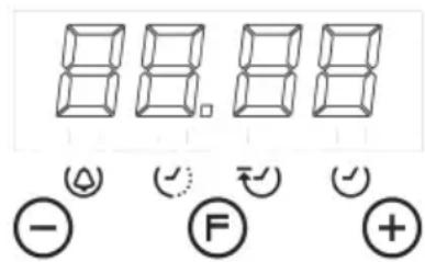
Description of the timer functions:

Warning alarm

Cooking in automatic mode (duration)

End of cooking time (time at end)

Setting the clock. Clock with 24-hour display.
Description of the buttons:

Reduce Minutes

Timer function selector

Increase Minutes
Warning alarm
An independent audible signal that can be set to a maximum time of 23 hours and 59 minutes. To set the time, press ☐once. The alarm indicator will flash for 5 seconds, during which time we can select the required time by pressing ☐and . The countdown will start immediately. At the end of the time, the indicator will flash and an intermittent sound signal will be triggered, which can be interrupted by pressing the button. If it is not stopped, it will do so automatically after 2 minutes. The warning alarm does not control any of the oven functions.
Semi-automatic cooking
A. Cooking time setting
By pressing ⏻ twice, set the cooking time using Ⓗ and Ⓕ. The cooking will start immediately and appear on the ⏻ indicator. At the end of the set time, the cooking will be interrupted and the intermittent sound signal will be heard. Cancel it as indicated above.
Note that the oven will continue to work after the end of the cooking process and when the alarm has been stopped. It must be turned off manually.
B. Setting the cooking end time 😊
By pressing three times, set the chosen cooking end time using and. The cooking will start immediately and appear on the indicator. When the cooking time ends, the cooking will stop and the intermittent sound signal will be heard. Cancel it as indicated above.
The programming status can be seen at any time by pressing Ⓕ. The programming can also be cancelled at any time by pressing and resetting the display. Pressing after this will prepare the oven for manual operation.
Note that the oven will continue to work after the end of the cooking process and when the alarm has been stopped. It must be turned off manually.
Automatic cooking.
(Start and end of cooking)
1) Programme the cooking time by pressing twice and selecting the required time with and.
2) Set the end of the cooking time by pressing F3 times and selecting the required time with and.
3) Select the required temperature and function using the thermostat controls and selector.
After these operations, the and indicators will continue to be shown on the display, showing that the oven has been programmed.
Practical example:
We want to cook for 45 minutes and for the cooking to end at 2 p.m.
- We press(F) twice and select 0.45 by using(-) and (+)
- We press(F) three times and select 14.00 with (-) and (+)
- After these operations, the current time will reappear on the display and the C and indicators will show that our programming has been understood and memorised.
- At 1.15 p.m. (2 p.m. less 45 minutes), the oven automatically.
- At 2 p.m. the cooking will stop automatically and intermittent sound signal will be heard.
- We can switch it off by pressing any button.
Note that the oven will continue to work after the end of the cooking process and when the alarm has been stopped. It must be turned off manually.
Setting the clock
When turning on the oven (and also after any possible power cut) the numbers 12.00 will appear in the panel and the ⏻ indicator will flash until we enter the right time.
To set the right time, press ☑ or ☒ to adjust. There is a 5-second lapse for acceptance during which no button must be touched. The rate of change will increase considerably a few seconds after the buttons have been depressed.
To change the clock time, we can press ⏻ times until the ⏻ indicator flashes and set the correct time with ⏻ and ⏻
NB
WARNING! any power cut cancels the programmed functions, including the clock. When the power supply returns, the 🤒 indicator will flash and can be reprogrammed
CLEANING THE APPLIANCE
IMPORTANT
As a safety precaution, before beginning to clean the oven always unplug it from the power supply or remove the appliance power lead.
Cleaning an oven that does not self-cleaning panels must be done after use, when it is switched off but still warm, not hot, so that the film of grease produced by the cooking vapours on the walls is still easy to remove, as well as the drips and splashes of fat that are not yet hard and dry.
Remove the chrome-plated wire side supports; pull the front part upwards to unattach them from the wall and remove them from the rear orifices. Clean the oven with a soft cloth soaked in a diluted ammoniac solution; rinse and dry. If there are still stains and splashes, place a damp cloth soaked in ammoniac at the back, close the door and, after a few hours, wash the oven with warm water and liquid detergent, rinse and dry carefully. To clean the shiny metal outside doors, use a soft cloth with soap and water; do not use any powdered products that contain abrasive substances.
Also avoid the use of acid or alkaline substances (lemon juice, vinegar, salt, tomatoes, etc.). Avoid using products containing chlorine, acid or abrasive substances specially for cleaning the varnished walls. Do not use thick steel wool or hard utensils, as they can damage the surface finishes.
Do not use high pressure cleaners or steam appliances for cleaning the oven.
Normally, wiping with a damp soft cloth and warm detergent is enough, but for stubborn stains the following is recommended:
OVEN CLEANING SYSTEM EQUIPPED WITH THE AQUAS-MART SYSTEM
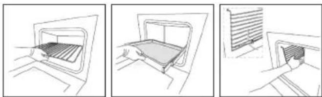
1 Take out the internal components: tray, screen, side screens.
natural_image
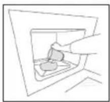
Three-step line drawing showing a door opening, a tray being placed, and a vent with liquid level (no text or symbols)2 Pour 200 ml of soapy water on the bottom of the oven
natural_image
Simple line drawing of a hand inserting a capsule into a container (no text or symbols)3.Turnon and set the oven at 200° for 15 minutes
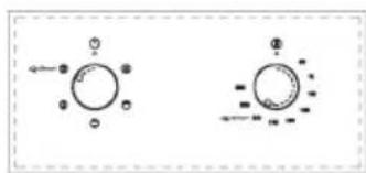
chemical
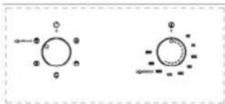
Two molecular orbital diagrams showing electron density distributions around a central atom- Move the temperature control from 200^ C to 0^ C. Let the oven cool down for 20 minutes.
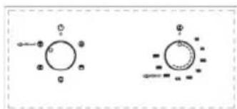
chemical
Simple molecular structure diagram showing two circular arrangements with substituents and bonds- Move the AquaSmart function to 0. Wipe clean with a rag or soft cloth.
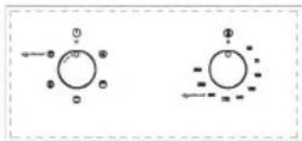
chemical
Two molecular orbital diagrams showing electron density distributions with labeled orbitals and spin directionsVITRIFIED ENAMELLED PARTS
Only use a recommended cleaner for this type of material – avoid chloride-based products such as bleach.
GLASS DOOR PANEL
Do not use abrasive products which could damage the glass. Remember that if the surface of the glass panel becomes scratched, it could cause a dangerous failure.
To simplify the cleaning, the inner glass panel can be taken out of the door. The method for removing the glass from the three types of door is shown below.
Door type A
After removing the screws fixing the glass, located on the inner face of the door, lift the glass out carefully. In versions with three glasses the intermediate glass can also be removed. The procedure is the same as above.
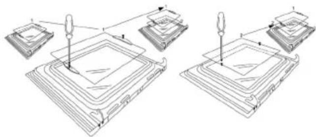
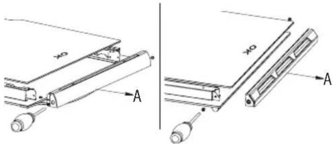
Door type B1 / B2
After removing the screws fixing the upper support of the glass, remove the support in direction "A". Then the glass can be pulled out. In versions with three glasses the intermediate glass can also be removed.
Door type C
Carefully lever up the glass with a flat screwdriver located in the groove shown in the figure.
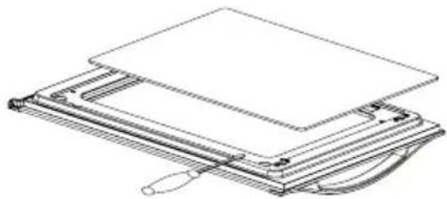
natural_image
Line drawing of a mechanical device with layered components and a handle (no text or symbols)When refitting the glass, check that it is correctly fitted into the toothed joint of the door and all around.
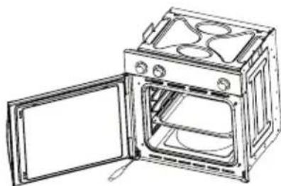
To simplify cleaning the interior of the oven, the door can be removed. The process of removing the door for the three types is shown below:
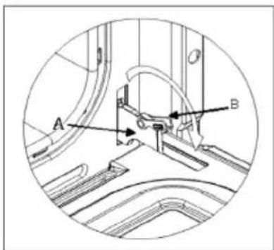
Door type A / B2
The hinges "A" have two moving bolts "B".
When the bolt "B" is lifted, the hinge comes out of its housing.
Then close the door to the half-way position.
Next, lift the door upwards and remove it, sliding it outwards; hold the door by the sides close to the hinges when doing this. To replace the door, first slide the hinges into their grooves and open the door completely.
Remember to turn the two moving bolts "B" used to engage the two hinges before closing the door (Fig. 3).
WARNING
- Take care not to remove the hinge locking system when taking off the door, as the hinge mechanism can spring back suddenly.
- Never submerge the door in water for any reason.
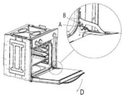
Door type B1
Open the door fully to position "D"
Lift the two mobile links "A" of the hinges, until fixing at point "B".
Then close the door to the half-way position.
Next, lift the door upwards and remove it, sliding it outwards; hold the door by the sides close to the hinges when doing this.
To replace the door, first slide the hinges into their grooves and open the door completely.
Remember to turn the two moving links "B" used to engage the two hinges before closing the door (Fig. X).
WARNING
• Take care not to remove the hinge locking system when taking off the door, as the hinge mechanism can spring back suddenly.
- Never submerge the door in water for any reason.
Door type C
Open the door and support it firmly.
Using a suitable screwdriver remove the lower hinge by the part fixed to the oven.
Then remove the upper hinge from its place and take off the door.
To replace the door, follow the same steps in reverse.
natural_image
Line drawing of an open oven with doors open, showing internal compartments and ventilation ducts (no text or symbols)Oven accessories (Fig. 4)
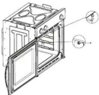
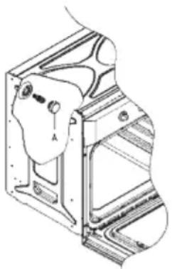
The oven can be provided with lateral guides fitted to the oven wall. Insert the grid and oven sheet provided on the lateral guides. To remove the guides proceed as follows for the two types:
Bars type 1
To remove the lateral guides press downwards at point A.
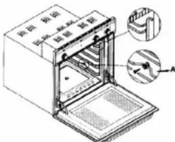
To remove the lateral guides take out the screw using a suitable screwdriver, lift the bars upwards until they are free.
natural_image
Technical line drawing of an oven with internal compartments and doorways (no text or symbols)INSTRUCTIONS FOR INSTALLATION
This appliance must be installed by a competent person, in accordance with the current version of the UK Safety Rules and Regulations or their European equivalent:
Urban development regulations (published by the Department of Environment).
Urban development laws (published by the Scottish Executive Development Department).
IEE wiring regulations.
Electricity in labour regulations.
PRIOR START-UP OF THE APPLIANCE
When it is unpacked, check that the following parts are with the oven:
• Instructions and Installation Manual
- Oven grid
- 1 tray
- Screws and stoppers for fitting the appliance in the housing
FITTING THE APPLIANCE (see Fig. 5)
These appliances are classified as Class I.
The earth is obligatory as provided for by law. The manufacturer declines all liability in the event that the accident prevention rules have not been followed.
IMPORTANT
The adjacent piece or furniture or cupboard and all the materials used in the installation must resist a minimum temperature increase of 85 °C above the ambient temperature during use of the appliance.
Certain types of vinyl or laminated kitchen furniture are particularly susceptible to damage due to decolouration at temperatures below those indicated.
If the appliance is installed without paying attention to this temperature limit or if it is placed less than 4 mm from the adjacent cupboards, liability will belong to the owner.
INSTALLATION NOTES
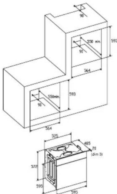
- The oven has to be installed in a standard gap of 600mm, as indicated in Fig. 5, whether under a hob or in a column.
- On inserting the oven in a column, it is essential in order to ensure there is enough ventilation, to remove the rear panel of the furniture and have an opening of at least 85-90mm as indicated in Fig. 5.
- Check that the oven has been fixed securely in the housing. Fixing the oven into the cupboard is done using 4 screws "A" Fig.5. One in each corner of the oven door frame.
Fig. 5: Installation distanced for simple electric ovens of 60 cms wide (the shape of the upper casing may vary) and attachment to the cupboard.
BUILT IN DIMENSION FOR OVEN WITH DOOR THICKNESS OF 26mm (dim A)
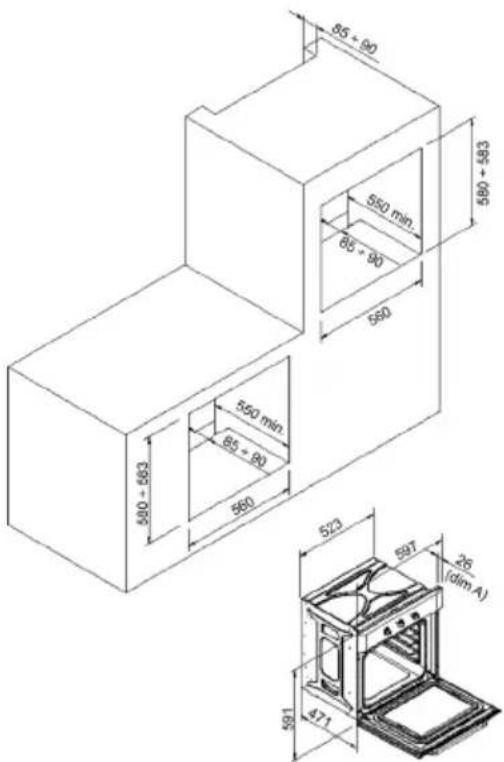
BUILT IN DIMENSION FOR OVEN WITH DOOR THICKNESS OF 20mm (dim B)
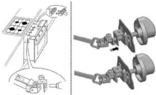
- When installing multipurpose ovens install the s shown in figure n°6.
natural_image
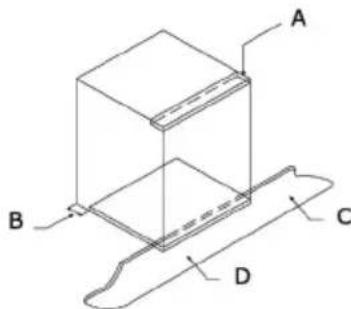
Technical illustration showing a battery connected to a motor and two separate motors with rotating components (no text or symbols)A. The support runner must be removed
B. Spacing of 75-90 mm between the wall and the rear part of the support shelf and the base of the cupboard
C. Base
D. False box front to be assembled
Fig. 7: Ventilation and gap requirements for the installation of e simple electric oven in a standard cooking unit. Minimum ventilation requirements for upper, base and support shelves for the rear part of the unit.
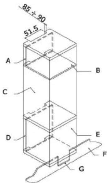
A.Rearpanel
B. Storagespace
C. Remove the rear part of this section
D.Realpanel
E.Storagespace
F.Base
G. Minimum ventilation gap 80 cm²
Fig. 8: Ventilation and gap requirements for the installation of a simple electric oven in an upper cupboard.
ELECTRICAL CONNECTION
Before connecting the appliance, check that the voltage marked on the specifications plate coincides with the voltage of the electricity network.
The NICEIC register is recommended for electrical installations.
WARNING – THIS APPLIANCE MUST BE EARTHED
This appliance must be wired to a 13 A bipolar automatic switch with protected socket, which has a 3 mm separation between contacts and is placed in an easily accessible place next to the appliance.
IMPORTANT
The conductors of the network power supply lead are coded by colours are follows:
Green and yellow -Earth
Blue - Neutral
Brown - Live
- The green and yellow conductor must be connected to the terminal marked "E" or with the symbol of the earth or which is green and yellow.
- The blue conductor must be connected to the term marked "N".
- The brown conductor must be connected to the ten marked "L".
- The lead must not reach a temperature higher than above the ambient temperature at any point.
- If the power lead is damaged, it must be replaced by a special lead or unit supplied by the manufacturer or it after-sales service.
REPLACEMENT OF THE NETWORK POWER SUPPLY LEAD
If it is necessary to replace the network power supply lead, proceed as follows:
- Disconnect the appliance from the power supply, unscrews the fastening screws and remove the rear panel.
- Unscrew the fastening screws and those of the terminals to free the existing lead.
- Assemble the replacement lead which must comply with the information listed in the Specifications, ensuring the correct connection of the colour codes and that all the screws are correctly tightened.
MAINTENANCE
Before carrying out maintenance, disconnect the appliance from the power supply.
During the guarantee period, if necessary all services should be commissioned to the Manufacturer's Technical Assistance Service Department. Bear in mind that intervention or repair by unauthorised personnel will invalidate this guarantee.
REPLACEMENT OF THE OVEN LIGHTBULB
(Not covered by the appliance guarantee.)
The oven has a light with the following characteristics: 15 W or 25 W, 300 °C and type E-14
WARNING: Disconnect the appliance from the electricity supply, remove the oven door (as described above), as well as the oven shelves.
Remove the glass cover that protects the light bulb by turning it anti-clockwise. Fig. 9 (A)
Unscrew the old light bulb and dispose of it safely and ecologically, change it for one as specified in the Specifications and replace the cover.
NOTE – The glass cover may be tight and, therefore, may need a grip to release it.
natural_image
Technical line drawing of a mechanical assembly with no visible text or symbolsCARE AND REPLACEMENT OF THE CATALYTIC COVERING
(When assembled, the covering is not covered by the appliance guarantee).
In order to keep the covering "always clean" efficiently, the oven must be heated to a minimum of 200^ whenever there are stubborn stains, so that they do not become permanent.
If the covering becomes black and shiny, they must be replaced. Remove all the internal accessories to facilitate the replacement of the covering.
The replacement covering may be bought directly from the Manufacturer's Replacement Part Department (see details included in the cover). Indicate the reference numbers of the product type described in the specifications plate and/or the series number of the appliance on ordering.
SPECIFICATIONS
INTERIOR DIMENSIONS
Height: 340 mm
Width: 440 mm
Depth: 390 mm
Useful volume: 59 litres
ELECTRICAL INFORMATION
Nominal voltage:
220 V - 240 V \~ 50 Hz
Power connection: 13A (automatic bipolar switch with protected socket, with 3mm separation between contacts)
POWER ABSORPTION
Base Resistance: 1,30 kW
Roof Resistance: 0,90 kW
Fan Resistance: 2,30 kW
Grill Resistance: 1,35 kW
Network power cable:
3 x 1.5 mm² type H07RN-F
Oven light bulb:
15 W - 25 W / 300 °C screw type E-14
The Manufacturer declines all liability for damage caused to persons and objects due to incorrect or improper installation of the appliance.
The Manufacturer reserves the right to make any modification it believes necessary and useful to the products, without prior warning.
ISTRUZIONI PER L'UTENTE
natural_image
Simple line drawing of a hand inserting a small object into a container (no text or symbols)chemical
Two molecular orbital diagrams showing electron density distributions around a central atomnatural_image
Two simple circular diagrams with dots and lines, no text or symbols presentchemical
Two molecular diagrams showing electron configuration with labeled charges and directional arrowsPEZZI SMALTATI VETRIFICATI
natural_image
Technical line drawing of a mechanical assembly with multiple components and alignment arrows (no text or symbols)Sportello del Tipo B1 / B2
natural_image
Technical line drawing of a mechanical assembly or holder device (no text or symbols)AVVISO
natural_image
Line drawing of an open microwave oven with doors open (no text or symbols)natural_image
Technical line drawing of an open oven or oven unit with internal compartments and mounting holes (no text or symbols)natural_image
Diagram showing a battery connected to a motor via cableging, with two separate views of the same components (no text or symbols present)natural_image
Technical line drawing of a mechanical bracket assembly (no text or symbols)Volume utile: 59 litri
DATI ELETTRICI
Tensione nominale:
220 V - 240 V \~ 50 Hz
WAARSCHUWING en VEILIGHEIDSVOORSCHRIFTEN
natural_image
Three-step line drawing showing a door opening process: opening, holding a tray, and opening with a slatted cover (no text or symbols)natural_image
Simple line drawing of a hand inserting a capsule into a container (no text or symbols)natural_image
Two abstract diagrams with circular elements and directional arrows, no text or symbols presentchemical
Simple molecular structure diagram showing two circular arrangements with substituents and bondschemical
Two molecular diagrams showing electron configuration with labeled charges and directional arrowsVERGLASTE EMAILDELEN
natural_image
Technical line drawing of a mechanical assembly with multiple components and mounting features (no text or symbols)Deurtype B1 / B2
Deurtype C
natural_image
Technical line drawing of a mechanical assembly with layered components and a curved base (no text or symbols)WAARSCHUWING
WAARSCHUWING
natural_image
Line drawing of an open oven with doors open, showing internal appliances and ventilation (no text or symbols)Accessoires van de oven (Fig. 4)
natural_image
Technical line drawing of an open oven or rack unit with internal compartments and mounting holes (no text or symbols)natural_image
Technical illustration showing a battery connected to a motor and two separate motors with rotating components (no text or symbols)WAARSCHUWING – DIT APPARAAT MOET GEAARD WORDEN
natural_image
Technical line drawing of a mechanical assembly with no visible text or symbolsZORG EN VERVANGING VAN DE KATALYTISCHE BEKLEDING
natural_image
Three-step line drawing showing a door opening process: opening, opening with a tray, and opening with a slatted cover (no text or symbols)natural_image
Simple line drawing of a hand inserting a small object into a container (no text or symbols)chemical
Two molecular orbital diagrams showing electron density distributions around a central atom4 Mover o regulador de temperatura entre 200 °C e 0 °C. Deixar arrefecer o forno durante 20 minutos.
chemical
Two molecular structures with electron density clouds and labeled atomschemical
Simple molecular structure diagram showing two circular arrangements with labeled atoms and directional arrowsPEÇAS ESMALTADAS VITRIFICADAS
natural_image
Technical line drawing of a mechanical assembly with multiple components and alignment arrows (no text or symbols)Tipo de porta B1 / B2
Tipo de porta C
natural_image
Technical line drawing of a layered electronic device with a flat top and curved base (no text or symbols)ADVERTÊNCIA
natural_image
Line drawing of an open oven with doors open, showing internal structure (no text or symbols)Grelha tipo 2
natural_image
Technical line drawing of an open oven or rack unit with internal compartments and mounting holes (no text or symbols)natural_image
Diagram showing a battery connected to a switch and two separate motor stators (no text or symbols present)A. A guia de suporte deve ser retirada
B. Espacejado 75-90 mm entre a parede e a parte traseira da estante de suporte e a base do armário
C. Soco
D. Frente de gaveta falsa a montar
natural_image
Technical line drawing of a mechanical assembly with no visible text or symbolsnatural_image
Simple line drawing of a door with a tray inside, no text or symbols present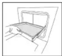
natural_image
Line drawing of a hand opening a tray with a rectangular frame (no text or symbols)
natural_image
Line drawing of a person opening a door with a window on the wall (no text or symbols)natural_image
Simple line drawing of a hand inserting a capsule into a container (no text or symbols)chemical
Two molecular orbital diagrams showing electron density distributions with labeled orbitals and directional arrowschemical
Two molecular orbital diagrams showing electron density distributions around a central atomchemical
Two molecular orbital diagrams showing electron density distributions with labeled orbitals and bonding patternsnatural_image
Technical line drawing of a mechanical assembly with multiple components and alignment indicators (no text or symbols)Вид дверцы B1 / B2
Вид дверцы С
natural_image
Line drawing of a mechanical device with layered components and a handle (no text or symbols)ВНИМАНИЕ
natural_image
Line drawing of an open microwave oven with doors open (no text or symbols)Решетка вид 2
natural_image
Technical line drawing of an open oven or refrigerator with internal compartments and mounting holes (no text or symbols)natural_image
Technical illustration showing a battery connected to a motor and its wiring with three motors (no text or symbols present)natural_image
Technical line drawing of a mechanical bracket or housing component (no text or symbols)natural_image
Three-step line drawing showing a door opening, hand placing a tray, and finally opening a vent with a slatted cover (no text or symbols)natural_image
Simple line drawing of a hand inserting a coin into a container (no text or symbols)chemical
Diagram showing electron spin states in a molecular orbital configuration, with arrows indicating spin direction and dashed lines representing electron density.chemical
Two molecular structures with labeled atoms and bonds, possibly representing a cyclic compound or ion exchange systemchemical
Two molecular diagrams showing electron density distributions with labeled charges搪瓷部件
B1 / B2 型门
c 型门
natural_image
Technical line drawing of a mechanical assembly with layered components and a curved base (no text or symbols)警告
natural_image
Line drawing of an open oven with internal appliances (no text or symbols)烤箱配件(图 4)
2 型导轨
natural_image
Technical line drawing of an open oven with internal compartments and mounting holes (no text or symbols)安装说明
natural_image
Technical illustration showing a battery pack connected to a motor and two separate motors with rotating components (no text or symbols)natural_image
Technical line drawing of a mechanical assembly with no visible text or symbols催化涂层的保养与更换
(组装后,涂层不在产品保修范围内)。

- PIEZAS ESMALTADAS VITRIFICADAS
- Tipo de puerta C
- ADVERTENCIA
- Reja tipo 2
- CONEXIÓN ELÉCTRICA
- EMAILIERTE TEILE
- Tür vom Typ B1 / B2
- Tür vom Typ C
- WICHTIGER HINWEIS
- Gitter vom Typ 2
- Type de porte C
- AVERTISSEMENT
- Grille type 2
- IINSTRUCTIONS POUR L'INSTALLATION
- BRANCHEMENT ÉLECTRIQUE
- ENTRETIEN ET REMPLACEMENT DES REVÊTEMENTS CATALITIQUES
- GENERAL INFORMATION
- IMPORTANT NOTICE
- SAFETY INSTRUCTIONS AND WARNING
- INSTRUCTIONS
- USING THE OVEN
- USEFUL ADVICE
- COOKING INSTRUCTIONS
- HOW TO USE THE GRILL
- WARNING
- Description of the timer functions:
- Description of the buttons:
- Warning alarm
- Semi-automatic cooking
- Cooking time setting
- Setting the cooking end time 😊
- Automatic cooking.
- Setting the clock
- CLEANING THE APPLIANCE
- IMPORTANT
- OVEN CLEANING SYSTEM EQUIPPED WITH THE AQUAS-MART SYSTEM
- VITRIFIED ENAMELLED PARTS
- GLASS DOOR PANEL
- Door type A
- Door type B1 / B2
- Door type C
- Door type A / B2
- Door type B1
- Oven accessories (Fig. 4)
- Bars type 1
- INSTRUCTIONS FOR INSTALLATION
- PRIOR START-UP OF THE APPLIANCE
- FITTING THE APPLIANCE (see Fig. 5)
- INSTALLATION NOTES
- ELECTRICAL CONNECTION
- WARNING – THIS APPLIANCE MUST BE EARTHED
- REPLACEMENT OF THE NETWORK POWER SUPPLY LEAD
- MAINTENANCE
- REPLACEMENT OF THE OVEN LIGHTBULB
- CARE AND REPLACEMENT OF THE CATALYTIC COVERING
- SPECIFICATIONS
- INTERIOR DIMENSIONS
- ELECTRICAL INFORMATION
- ISTRUZIONI PER L'UTENTE
- PEZZI SMALTATI VETRIFICATI
- Sportello del Tipo B1 / B2
- AVVISO
- DATI ELETTRICI
- WAARSCHUWING en VEILIGHEIDSVOORSCHRIFTEN
- VERGLASTE EMAILDELEN
- Deurtype B1 / B2
- Deurtype C
- WAARSCHUWING
- Accessoires van de oven (Fig. 4)
- WAARSCHUWING – DIT APPARAAT MOET GEAARD WORDEN
- ZORG EN VERVANGING VAN DE KATALYTISCHE BEKLEDING
- PEÇAS ESMALTADAS VITRIFICADAS
- Tipo de porta B1 / B2
- Tipo de porta C
- ADVERTÊNCIA
- Grelha tipo 2
- Вид дверцы B1 / B2
- Вид дверцы С
- ВНИМАНИЕ
- Решетка вид 2
- 搪瓷部件
- B1 / B2 型门
- c 型门
- 警告
- 烤箱配件(图 4)
- 型导轨
- 安装说明
- 催化涂层的保养与更换
Brand : CATA
Model : ME 605 TC
Category : Oven