
G0063341 - Camera Generac - Free user manual and instructions
Find the device manual for free G0063341 Generac in PDF.
| Product Type | Single Load Manual Transfer Switch for Portable Generator |
| Model | G0063341 (equivalent to models 6333 and 6334) |
| Rated Voltage | 120/240 V AC, single phase |
| Max Rated Current | 60 A (model 6333) or 100 A (model 6334) |
| Max Compatible Generator Power | 15,000 W (6333) / 25,000 W (6334) continuous |
| Enclosure Type | NEMA 1 (indoor use) |
| Included Circuit Breakers | Main utility 60/100 A, main generator 60/100 A (depending on model) |
| Dimensions (approx.) | 30 × 20 × 15 cm |
| Weight (approx.) | 5 kg |
| Main Functions | Safe switching between utility and generator, mechanical interlock to prevent simultaneous connection, integrated circuit breakers for protection |
| Maintenance and Cleaning | Clean regularly with a dry cloth; visually inspect connections; perform a function test at least once a month |
| Safety | Installation by qualified electrician required; risk of electric shock, fire and explosion; observe safety distances for the generator (5 ft from openings) |
| Spare Parts and Repairability | Original Generac parts available; repair by an authorized center; manual included |
| General Information | Manufactured by Generac Power Systems; compliant with local electrical codes; California Proposition 65 warning |
Frequently Asked Questions - G0063341 Generac
User questions about G0063341 Generac
0 question about this device. Answer the ones you know or ask your own.
Ask a new question about this device
Download the instructions for your Camera in PDF format for free! Find your manual G0063341 - Generac and take your electronic device back in hand. On this page are published all the documents necessary for the use of your device. G0063341 by Generac.
USER MANUAL G0063341 Generac
Installation Guidelines
For
SE-Rated Single Load Manual
Transfer Switches 6333 / 6334
DANGER!

NOT INTENDED FOR USE IN CRITICAL LIFE SUPPORT APPLICATIONS.

ONLY QUALIFIED ELECTRICIANS OR CONTRACTORS SHOULD ATTEMPT INSTALLATION!
This manual should remain with the unit.
This manual must be used in conjunction with the appropriate owner's manual.
Forward
Thank you for purchasing a Generac Single Load Manual Transfer Switch to safely connect a portable generator to your home or business (single phase only), recommended to be used as the disconnect panel for a single 120/240VAC load or to feed a subpanel for multiple loads, see Installation Diagrams for typical installations. Use where the main electrical panel is located indoors. This product is suitable for service entrance equipment.
READ THIS MANUAL THOROUGHLY. This manual has been prepared to familiarize personnel involved with the installation of transfer switches with the manufacturer's installation requirements. Information and instructions contained herein are not intended to replace or supersede, local, state, or national safety, electrical, and building codes pertaining to such installations. Applicable laws, codes, and standards must always take precedence over the recommendations contained herein. Always check with the local Authority Having Jurisdiction (AHJ) for the codes or standards that apply.
Only authorized dealers or qualified, competent installation contractors or electricians thoroughly familiar with applicable codes, standards, and regulations should install this standby electric power system. The installation must be in strict compliance with all codes, standards, and regulations.
It is not intended that this manual be used by any unqualified person for the purpose of installing a transfer switch. Installation, inspection, and testing of the system must be attempted only by competent, qualified electricians or installation contractors who are familiar with the equipment and with all installation codes and requirements.
It would be impossible to provide details for every installation configuration. For this reason, much of the information in this manual is general in nature. Illustrations of typical installations are not intended to serve as specific installation plans, but may be used in the planning and design process when considering the selection and purchase of a generator set for standby power applications. Always have the unit specific drawings and manuals on hand before beginning any installation.
CAUTION!

If a portable generator is used to power electrical load circuits normally powered by a utility power source, it is required by code to install a transfer switch. The transfer switch must effectively isolate the electrical system from the utility distribution system when the generator is operating. Failure to isolate an electrical system by such means may result in damage to the generator and may also result in injury or even death to utility power workers due to backfeed of electrical energy.

After the transfer switch has been installed, do nothing that might render the installation in non-compliance with such codes, standards, and regulations. Every effort was made to ensure that the information in this manual was both accurate and complete at the time it was released. However, the manufacturer reserves the right to change, alter, or otherwise improve this product at any time without notice.
WARNING!
California Proposition 65
Engine exhaust and some of its constituents are known to the state of California to cause cancer, birth defects, and other reproductive harm.
WARNING!
California Proposition 65
This product contains or emits chemicals known to the state of California to cause cancer, birth defects, and other reproductive harm.
Table of Contents
Forward ....ii
Section 1 Safety
1.1 Introduction ...... 1
1.2 Safety Rules .... 1
1.3 General Hazards ...... 2
1.4 Electrical Hazards ...... 2
1.5 Fire Hazards .... 3
1.6 Explosion Hazards .... 3
1.7 Standards Index .... 3
Section 2 Installation
2.1 Contents....5
2.2 Required Tools .... 5
2.2.1 Tools and Items Needed for Installation....5
2.2.2 Optional Items for Installation
2.3 Specifications....5
2.4 Transfer Switch Installation 6
2.5 Wiring Diagram 6
Section 3 Operation
3.1 Transferring from Utility Power to Generator Power 7
3.2 Transferring from Generator Power to Utility Power 7
This page intentionally left blank.
1.1 — Introduction
Thank you for purchasing a Generac Single Load Manual Transfer Switch to safely connect a portable generator to your home or business (single phase only), recommended to be used as the disconnect panel for a single 120/240VAC load or to feed a subpanel for multiple loads, see Installation Diagrams for typical installations. Use where the main electrical panel is located indoors. This product is suitable for service entrance equipment
Read this manual thoroughly. If any portion is not understood, contact the nearest Authorized Generac Service Dealer for clarification. These individuals are trained/qualified service technicians familiar with the control systems and available options, and also have full access to drawings, publications, and other information required for a successful installation.
1.2 — Safety Rules
Throughout this publication, DANGER, WARNING, CAUTION, and NOTE boxes are used to alert personnel to special instructions about a particular operation that may be hazardous if performed incorrectly or carelessly. Observe them carefully. They indicate:
DANGER!
Indicates a hazardous situation or action that, if not avoided, will result in death or serious injury.
WARNING!
Indicates a hazardous situation or action that, if not avoided, could result in death or serious injury.
⚠️ DANGER!
Indicates a hazardous situation or action that, if not avoided, could result in minor or moderate injury.
NOTE: Notes provide additional information important to a procedure or component.
These safety warnings cannot eliminate the hazards they indicate. Observing safety precautions and strict compliance with the special instructions while performing the action or service are essential to preventing accidents.
Four commonly used safety symbols accompany DANGER, WARNING, and CAUTION boxes and the type of information each indicates:

This symbol points out important safety information that, if not followed, could endanger personnel and/or property.

This symbol represents the potential for an Explosion Hazard.

This symbol represents the potential for a Fire Hazard.

This symbol represents the potential for an Electrical Shock Hazard.

SAVE THESE INSTRUCTIONS. This manual contains important instructions that should be followed during installation of the transfer switch. The manufacturer suggests that these safety rules be copied and posted in potential hazard areas. Safety should be stressed to all installers, operators, potential operators, and service and repair technicians for this equipment.
The manufacturer cannot anticipate every possible circumstance that might involve a hazard. The warnings in this manual, and on tags and decals affixed to the unit, are not all-inclusive. If using a procedure, work method, or operating technique the manufacturer does not specifically recommend, ensure that it is safe for others. Also make sure the procedure, work method, or operating technique used does not result in unsafe conditions.
1.3 — General Hazards
- For safety reasons, the manufacturer recommends that this equipment be installed, serviced, and repaired by an Authorized Service Dealer or other competent, qualified electrician or installation technician who is familiar with all applicable codes, standards, and regulations.
- Ensure that the transfer switch is installed, operated, and serviced in accordance with the manufacturer's instructions and recommendations. Following installation, do nothing that might render the unit unsafe or in noncompliance.
- Keep the area around the transfer switch clean and uncluttered. Remove any materials that could become hazardous.
- When working on this equipment, remain alert at all times. Never work on the equipment when physically or mentally fatigued.
- Inspect the portable generator regularly, and promptly repair or replace any worn or damaged components using only factory approved parts and procedures.
1.4 — Electrical Hazards
- All generators produce dangerous electrical voltages and can cause fatal electrical shock. Utility power delivers extremely high and dangerous voltages to the transfer switch as well as the generator when it is in operation. Avoid contact with bare wires, terminals and other connections. Ensure all covers, guards, and barriers are in place, and that they are properly secured and/or locked before operation. If work must be done around an operating unit, stand on an insulated, dry surface to reduce potential shock hazard.
- Do not handle any kind of electrical device while standing in water, while barefoot, or while hands or feet are wet. DANGEROUS ELECTRICAL SHOCK MAY RESULT.
- If it is necessary to stand on metal or concrete while installing, operating, servicing, or repairing this equipment, lay down a dry wooden platform and cover with insulated mats before beginning.
- Verify that the portable generator is properly grounded.
- Wire gauge sizes of electrical wiring, cables, and cord sets must be adequate to handle the maximum electrical current (ampacity) to which it will be subjected.
- Before installing or servicing equipment, verify that all power voltage supplies are positively turned off at their sources. Failure to do so can result in hazardous and possibly fatal electrical shock.
- Connecting a portable generator to an electrical system normally supplied by an electric utility is by means of the transfer switch so as to isolate the generator's electric system from the electric utility distribution system when the portable generator is operating. Failure to isolate the two electric system power sources from each other by such means will result in damage to the portable generator and may also result in injury or death to utility power workers due to backfeed of electrical energy.
- In case of accident caused by electric shock, immediately shut down the source of electrical power. If this is not possible, attempt to free the victim from the live conductor. AVOID DIRECT CONTACT WITH THE VICTIM. Use a nonconducting implement, such as a dry rope or board, to free the victim from the live conductor. If the victim is unconscious, apply first aid and get immediate medical help.
- Do not wear jewelry when working on this equipment. Jewelry can conduct electricity resulting in electric shock, or may get caught in moving parts resulting in injury.
1.5 — Fire Hazards
- Keep a fire extinguisher near the portable generator and transfer switch at all times. Keep the extinguisher properly charged and be familiar with its use. Direct any questions to the local fire department.
NOTE: DO NOT use any carbon tetra-chloride type fire extinguishers. These fire extinguishers emit toxic fumes and the liquid can damage wiring insulation.
1.6 — Explosion Hazards
- Do not smoke around the generator. Immediately wipe up any fuel or oil spills. Ensure that no combustible materials are left in the generator compartment, or on or near the generator, as FIRE or EXPLOSION may result. Keep the area surrounding the generator clean and free of debris.
- All types of fuels are potentially FLAMMABLE and/or EXPLOSIVE and must be handled with care. Inspect the fuel system frequently and correct any leaks immediately. Be sure fuel supply lines are properly installed, purged, and leak tested before placing the generator set into service.
1.7 — Standards Index
Be sure the transfer switch is in strict compliance with all applicable local, state, and federal laws, codes, and regulations pertaining to such installations. Always use the current version or edition of the applicable law, code, and regulation as it applies to the local jurisdiction.
This page intentionally left blank.
2.1 — Contents
What is Included in this Carton:
- Manual Transfer Switch with Utility and Generator main breakers mechanically interlocked preventing utility and generator from powering the load at the same time
• Hardware Kit (including Bonding Screw and Label to convert switch to Service Entrance rating) - Documentation: Installation Manual and Product Registration card
2.2 — Required Tools
2.2.1—Tools and Items Needed for Installation:
- Safety eye goggles
- 1/4" and 11/32" nut drivers
• Straight blade and Phillips screwdriver - Electric drill and drill bits
- Wire cutter/stripper
- NEW 2-pole, 60 Amp or 100 Amp 125/250V circuit breaker to install in main load center (see Table 1) manufactured by same as main load center
- Appropriately sized conduit, fittings, lock nuts and wire
- Anchors and screws to mount transfer switch to wall
2.2.2—Optional Items for Installation:
- Power Inlet Box that mounts outside for convenient generator connection to transfer switch
- Power Cord to connect generator to transfer switch via the power inlet box
2.3 — Specifications
Table 1: SPECIFICATIONS
| Model 6333 6334 | ||
| Max Generator Size in Watts (continuous) | 15000 watts | 25000 watts |
| UTILITY MAIN breaker, 1 Included, 1 additional required | 60 Amp 100 Amp | |
| GEN MAIN breaker, included 60 Amp 100 Amp | ||
| NEMA Type Enclosure NEMA 1 NEMA 1 | ||
| Max 1-pole Circuits / Max 2-pole Circuits NO PROVISION FOR BRANCH CIRCUIT | NO PROVISION FOR BRANCH CIRCUIT | |
DANGER!

HAZARDOUS VOLTAGES ARE PRESENT INSIDE TRANSFER SWITCH ENCLOSURES THAT CAN CAUSE DEATH OR SEVERE PERSONAL INJURY. FOLLOW PROPER INSTALLATION, OPERATION AND MAINTENANCE PROCEDURES TO AVOID HAZARDOUS VOLTAGES.
⚠️ DANGER!

TURN OFF THE MAIN CIRCUIT BREAKER IN THE LOAD CENTER BEFORE STARTING INSTALLATION.
2.4 — Installation Procedure
- Transfer switch can be installed on either the left or right side of the main load center. Transfer switch is provided with 1/2" to 1-1/2" knockouts (KOs) to connect to the main load center and Power Inlet Box using installer-provided conduit, fittings and wire. The conduit should enter the main load center in one of the bottom or lower side KOs. If Service Entrance rating is desired, installer must install bonding screw in Hardware Kit (included) to neutral bar and must apply the Service Disconnect label to the transfer switch as part of the installation procedure.
- Remove covers from the main load center and transfer switch. Cut conduit to desired length. Attach fittings to the conduit and fittings/conduit assembly to both enclosures through the KOs with locknuts. Hold the transfer switch away from the load center against the wall on which it is to be mounted and mark the holes on the wall for the anchoring screws. Mount transfer switch to wall with anchors and screws (provided by installer).
- You are ready to terminate the wires in the manual transfer switch and load center. Install (installer provided) 60A or 100A 2P UTILITY MAIN circuit breaker in main load center. Pull appropriately sized wire (provided by installer) through conduit and connect RED and/or BLACK wire between the 2-Pole UTILITY circuit breaker in the transfer switch and the newly installed UTILITY circuit breaker in the main load center, WHITE wire to the neutral bar inside the transfer switch and main load center, and GREEN wire to the ground bar in transfer switch and main load center. If there is no separate ground bar in the main load center, connect GREEN wire into an open position in the NEUTRAL bar in the main load center, and tighten to the marked values.
- Locate and remove a KO on manual transfer switch for power feed from Power Inlet Box/generator. Install fitting/conduit as required and pull appropriately sized generator feed wire from Power Inlet Box/generator into manual transfer switch through conduit. Connect RED and/or BLACK wire to the GEN MAIN circuit breaker, WHITE wire to the neutral bar and GREEN wire to the ground bar in transfer switch and tighten to the marked values. Reinstall transfer switch and load center covers (screws for transfer switch provided in Hardware Kit bag).
- Turn ON the MAIN load center circuit breaker and all load center circuit breakers. Turn on UTIL MAIN circuit breaker in the manual transfer switch. Verify that power is restored to all appliances.
2.5 — Wiring Diagram
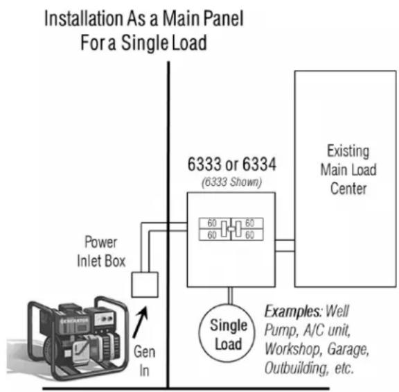
flowchart
graph TD
    A["Power Inlet Box"] --> B["6333 or 6334 (6333 Shown)"]
    B --> C["Existing Main Load Center"]
    D["Single Load"] --> B
    E["Examples: Well Pump, A/C unit, Workshop, Garage, Outbuilding, etc."] --> B
    F["Gen In"] --> B
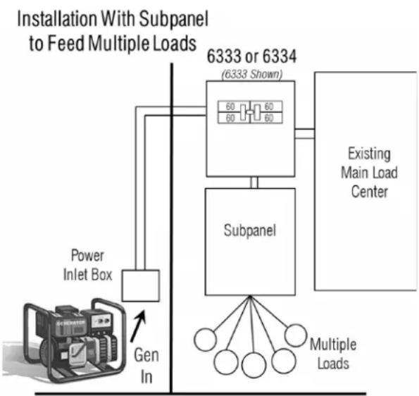
flowchart
graph TD
    A["Power Inlet Box"] --> B["Subpanel"]
    B --> C["Existing Main Load Center"]
    B --> D["Multiple Loads"]
    style A fill:#f9f,stroke:#333
    style B fill:#ccf,stroke:#333
    style C fill:#cfc,stroke:#333
    style D fill:#fcc,stroke:#333
3.1 — Transferring From Utility Power to Generator Power
⚠️ DANGER!

NEVER run portable generators indoors or in garages, basements, or sheds. Portable generators should always be used at least 5 feet away from windows, doors, vents, or any other opening. Carbon Monoxide (CO) from a generator is deadly and can kill you in minutes. Read and follow all generator directions before use.
- Move generator outdoors. Be sure your generator is located at least 5 feet from windows, doors or other openings to prevent dangerous carbon monoxide fumes from entering your home.
- Insert the male plug of the Power Cord into the correct outlet on the generator.
- Plug in the female connector of the Power Cord to the inlet (if provided) located on the bottom of the Transfer switch.
- Turn OFF all circuit breakers in the Transfer switch and Main load center.
- Start the generator outdoors, following the procedures described in the generator's Owner's Manual furnished by the manufacturer.
- Turn ON the GENERATOR MAIN circuit breaker in the Transfer switch.
- Turn ON individual circuit breakers in the Transfer switch and the Main Load Center up to the continuous wattage rating of your generator. If the Generator Main breaker trips, you have overloaded the generator. Some circuit breakers must be turned OFF to avoid damage to the generator or loads being connected.
DANGER
Using a generator indoors CAN KILL YOU IN MINUTES.
Generator exhaust contains carbon monoxide. This is a poison you cannot see or smell.
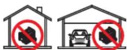
NEVER use inside a home or garage, EVEN IF doors and windows are open.
Only use OUTSIDE and far away from windows, doors, and vents.
3.2 — Transferring from Generator Power to Utility Power
- On the Transfer switch, turn OFF Generator MAIN breaker and turn ON Utility MAIN breaker. To do this, slide the interlock mechanism up with the left hand while turning ON the 200 amp circuit breaker.
- Turn ON any branch circuit breakers in the Transfer switch and Main Load Center that are OFF.
- Shut down the generator, following the procedures in the generator Owner's Manual.
- Unplug the power cord from the Transfer switch and then the generator.
- Let the generator cool down before storing in a dry, secured location.
- To ensure that your generator will work properly when you need it, it is important to start and run your generator under load regularly and keep the tank filled with fresh fuel. Perform the above steps at least ONCE A MONTH to keep the generator properly “exercised”. It is not necessary to turn off any circuits in the MAIN load center when supplying generator power to the transfer switch.
GENERAC®
Part No. 0K4444 Rev. B 07/15/2013 Printed in USA
© Generac Power Systems, Inc. All rights reserved
Specifications are subject to change without notice.
No reproduction allowed in any form without prior written consent from Generac Power Systems, Inc.
Generac Power Systems, Inc.
S45 W29290 Hwy. 59
Waukesha, WI 53189
1-888-GENERAC (1-888-436-3722)
generac.com
Section 2 Installation
- Installation Guidelines
- DANGER!
- Forward
- CAUTION!
- WARNING!
- Table of Contents
- Forward ....ii
- Section 1 Safety
- Section 2 Installation
- Section 3 Operation
- This page intentionally left blank.
- — Introduction
- — Safety Rules
- ⚠️ DANGER!
- — General Hazards
- — Electrical Hazards
- — Fire Hazards
- — Explosion Hazards
- — Standards Index
- — Contents
- — Required Tools
- 2.2.1—Tools and Items Needed for Installation:
- 2.2.2—Optional Items for Installation:
- — Specifications
- — Installation Procedure
- — Wiring Diagram
- — Transferring From Utility Power to Generator Power
- DANGER
- — Transferring from Generator Power to Utility Power
- GENERAC®
Brand : Generac
Model : G0063341
Category : Camera