 — Generator — Mode d'emploi PDF")
P2000i (2020) - Generator POLARIS - Free user manual and instructions
Find the device manual for free P2000i (2020) POLARIS in PDF.
| Brand | Polaris |
| Model | P2000i (2020) |
| Type | Inverter Generator |
| Rated power | 1,600 W |
| Maximum power | 2,000 W |
| AC output voltage | 120 V |
| Rated AC current | 13.3 A |
| AC outlets | 2 duplex outlets (4 outputs) |
| DC outlet | 1 12 V outlet (5 A) |
| USB ports | 2 USB ports (5 V, 3.1 A) |
| Engine | 4-stroke, single cylinder |
| Fuel | Unleaded gasoline, 87 octane or higher |
| Noise level | 70 dB(A) (moderate) |
| Idle system | Smart Throttle (automatic speed reduction) |
| Protection | AC/DC circuit breakers, overload protection, low oil shutdown |
| Parallel function | Yes (compatible with P2000i and P3200i) |
| Ignition | Recoil start (rope starter) |
| Grounding | Ground terminal on control panel |
| Usage | Outdoor only |
| Warranty | 2-year limited (plus emissions warranty) |
| Weight (estimated) | Approximately 22 kg |
| Routine maintenance | Oil change every 3 months/50 hours, air filter check, spark plug |
| Spare parts | Recommended genuine Polaris parts |
| Repairability | User maintenance, repairs by authorized dealer |
Frequently Asked Questions - P2000i (2020) POLARIS
User questions about P2000i (2020) POLARIS
0 question about this device. Answer the ones you know or ask your own.
Ask a new question about this device
Download the instructions for your Generator in PDF format for free! Find your manual P2000i (2020) - POLARIS and take your electronic device back in hand. On this page are published all the documents necessary for the use of your device. P2000i (2020) by POLARIS.
USER MANUAL P2000i (2020) POLARIS
FOR MAINTENANCE AND SAFETY
OWNER'S MANUAL
ENGLISH
FRANÇAIS CANADIEN
P2000I

WARNING
Read, understand, and follow all of the instructions and safety precautions in this manual and on all product labels.
Failure to follow the safety precautions could result in serious injury or death.

WARNING
Operating, servicing and maintaining this equipment can expose you to chemicals including engine exhaust, carbon monoxides, soots, mineral oils, and lead which are known to cause cancer and birth defects or other reproductive harm. To minimize exposure, avoid breathing exhaust, do not idle the engine except as necessary. Service and operate your equipment in a well-ventilated area and wear gloves or wash hands frequently when servicing your equipment.
For more information go to www.P65Warnings.ca.gov.
FOR MAINTENANCE AND SAFETY
OWNER'S MANUAL
P2000I
POLARIS® and POLARIS POWER® are trademarks of POLARIS Industries Inc.
Copyright 2019 Polaris Industries Inc. All information contained within this publication is based on the latest product information at the time of publication. Due to constant improvements in the design and quality of production components, some minor discrepancies may result between the actual product and the information presented in this publication. Depictions and/or procedures in this publication are intended for reference use only. No liability can be accepted for omissions or inaccuracies. Any reprinting or reuse of the depictions and/or procedures contained within, whether whole or in part, is expressly prohibited.
The original instructions for this product are in English. Other languages are provided as translations of the original instructions.
Printed in China
9931062 Rev 01
Designed in our labs, put to the test in yours.
Power for everything, for everyone. We've designed Polaris Power® with that simple principle in mind. From long weekend camping trips and tailgating to construction sites and power while you wait out the storm, we've got you covered.
Our line of generators are built for it all. No detail too small, no spec overlook. We've redefined the definition of limits, so you can keep redefining yours.
• P2000i Inverter Generator
• P3200iE Inverter Generator
• P5500 Open Frame Generator
• P6500 Open Frame Generator
Your owner's manual contains instructions for minor maintenance, but information about major repairs is outlined in the POLARIS Service Manual and can be performed by a factory certified Master Service Dealer® (MSD) Technician.
Your POLARIS dealer knows your generator best and is interested in your total satisfaction. Your POLARIS dealership can perform all of your service needs during, and after, the warranty period.
Introduction 7
Safety 11
Features and Controls 25
First Use Instructions . . . . . . . . . . . . . . . . 35
Operation 39
Emission Control Systems ..... 51
Maintenance 53
Specifications 73
POLARIS Products 75
Troubleshooting 77
Warranty 81
Maintenance Log 91
INTRODUCTION
OVERVIEW
For a safe and enjoyable operation of your new generator, please read the entirety of this owner's manual. If you should need additional assistance with generator operation or maintenance, please see your POLARIS dealer or other certified service technician.
After reading this manual in its entirety, store in a convenient location for futur reference.
NOTICE
You must complete the Warranty Registration Form included with your generator and forward it to POLARIS within 10 days of purchase. Warranty coverage will not be active unless your generator is registered.
INTENDED USE
The Polaris Power® Generator is intended to supply power. Such items include but are not limited to:
- Furnace fans
- Sump pumps
- Dishwashers
- Hotplates / stoves
- Washing machines
- Garage door openers
- Water heaters
- Refrigerators
- Circular saws
Items that use more than the recommended amount of combined power consumption should not be connected to this generator.
SAFETY SYMBOLS AND SIGNAL WORDS
The following signal words and symbols appear throughout this manual and on your generator. Your safety is involved when these words and symbols are used. Become familiar with their meanings before reading the manual.

DANGER
DANGER indicates a hazardous situation which, if not avoided, WILL result in death or serious injury.

WARNING
WARNING indicates a hazardous situation which, if not avoided, COULD result in death or serious injury.

CAUTION
CAUTION indicates a hazardous situation which, if not avoided, COULD result in minor to moderate injury.
NOTICE
NOTICE provides key information by clarifying instructions.
IMPORTANT
IMPORTANT provides key reminders during disassembly, assembly, and inspection of components.
The Prohibition Safety Sign indicates an action NOT to take in order to avoid a hazard.

The Mandatory Action Sign indicates an action that NEEDS to be taken to avoid a hazard.

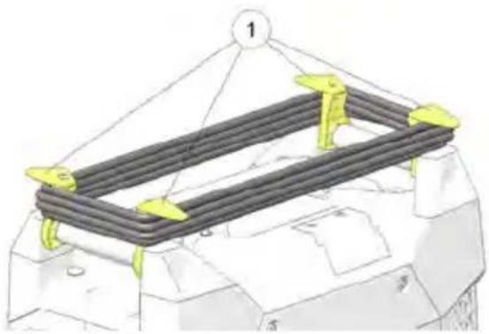
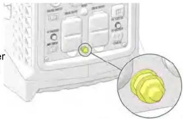
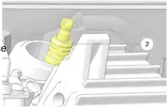
GENERATOR IDENTIFICATION NUMBERS
To view your generator's identification numbers, first remove the maintenance panel from the right side of the generator. The generator serial number be found stamped on the crankcase above the oil drain. The engine serial number ② is adhered to the side of the engine above the crankcase.
natural_image
Technical diagram of a mechanical assembly with numbered parts (1 and 2), no readable text or symbols present.Record your generator's serial numbers and purchase date in the spaces provided.
| Serial Number | |
| Generator Serial Number | |
| Purchase Date |
SAFETY
SAFETY WARNINGS
WARNING
Failure to follow recommended precautions and procedures could result in severe injury or death. Always follow all safety warnings on the product, and follow all operation, inspection, and maintenance procedures outlined in this manual.
Read and understand all of the safety and operating information in this manual and on the product before using the machine. Use the generator only as described in this manual.
Understand and follow all inspection and maintenance procedures outlined in this manual. Following these procedures will ensure that the generator remains in safe operating condition.
Turn the Engine switch to the OFF position. Turn off the gasoline valve and close the fuel cap vent when the generator is not in use for a long time.
WARNING
It is the responsibility of the owner to ensure that all users of this generator fully informed of the safety and operating information prior to use.
OPERATOR SAFETY
WARNING
Operating the generator with worn, damaged, or malfunctioning components could result in serious injury or death. Never start the engine without checkin all of the generator components to be sure of proper operation.
Please take the following precautions, which are essential for proper and safe operation:
- Read and understand all of the safety and operating information in this manual and on all warning and instruction labels before using the generator. Use the generator only as described in this manual and on the product.
- Know how to stop the generator quickly in case of emergency, see page 41 for information on stopping the unit quickly.
- Keep children, pets, and bystanders at a safe distance from the generator.
-
Review and understand the use of all generator controls, output receptacles, and connections.
-
Be sure that anyone who operates the generator receives proper instruction and reads this manual completely. Do not let children operate the generator.
- Use the generator only for intended purposes.
- Turn off the generator immediately if the unit begins to operate abnormally. After the generator has cooled, disconnect the generator and take to your authorized Polaris dealer.
- While operating the generator, if you experience a headache, fatigue, nausea / vomiting, confusion, or seizures, immediately get to fresh air. Do not delay and do not attempt to shut down the unit.
OPERATING WITHOUT INSTRUCTION

WARNING
Operating this generator without proper instruction increases the risk of severe injury or death.
The operator must understand how to operate the generator safely in proper conditions and environments.
All operators must read and understand the owner's manual and all warning and instruction labels before operating the generator.

natural_image
Blue circular icon with a white human figure reading a book (no text or symbols)FAILURE TO INSPECT BEFORE OPERATING

WARNING
Failure to inspect and verify that the generator is in safe operating condition before operating increases the risk of an accident resulting in severe injury or death.
Always perform the pre-operation inspection before each use of your generator to make sure it's in safe operating condition.
Always follow the inspection and maintenance procedures and schedules described in this owner's manual.
USING ALCOHOL OR DRUGS

WARNING
Never consume alcohol or drugs before or while operating this generator.
Operating this generator after consuming alcohol drugs could adversely affect operator judgment
or

CARBON MONOXIDE SAFETY

WARNING
Generator exhaust contains Carbon Monoxide (CO) vapors. Exposure to Carbon Monoxide by people or pets can result in SEVERE INJURY or DEATI ALWAYS operate generator according to all warning and instruction labels and this manual.
- This portable generator runs on gasoline. The generator exhaust vapor contains carbon monoxide (CO).
• Carbon monoxide is odorless. You cannot smell it. - Carbon monoxide is colorless. You cannot see it.
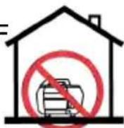
- The generator is for outdoor use only. Never run the generator in an enclosure area. Exhaust contains poisonous carbon monoxide vapor that can cause loss of consciousness or death. Operate the generator in an open, and well ventilated area.
- Do not use the generator indoors in garages, basements, crawl spaces, sheds, portable buildings, or similar areas even if doors and windows are open or if ventilating fans are used to circulate air.
- Do not use the generator near windows, doors, vents or any other building openings even if they are closed. Poor seals on a door, as one example, could still permit high levels of carbon monoxide to infiltrate the living area of home.
- Be sure to install approved carbon monoxide detectors in your home that have battery back-up systems that will continue to detect the presence of carbon monoxide during electric-power outages. Test these devices and replace batteries as recommended by their respective manufacturers.
IMPORTANT
If you experience a headache, fatigue, nausea / vomiting, confusion, or seizures, immediately get to fresh air and away from the unit. Do not delay any reason.
ELECTRICAL SAFETY
! DANGER
This generator produces high voltage electricity sufficient to cause death by electrocution.
- The generator produces enough electric power to cause serious shock or electrocution if misused.
- Always connect the generator to a suitable ground circuit.
- When servicing the generator, disconnect the spark plug wire and place it where it cannot contact the plug. Turn the engine switch to the OFF position.
- Do not check for a spark with the plug removed. Use only approved spark plug testers.
- Using a generator or electrical appliance in wet conditions, such as rain or snow, or near a pool or sprinkler system, or when your hands are wet, could result in severe shock or electrocution. Keep the generator dry and away from all sources of moisture.
- If the generator is stored outdoors, unprotected from the weather, check all electrical components on the control panel before each use. Moisture or ice can cause a malfunction or short circuit in electrical components that could result in electrocution.
- Do not connect the generator to a building's electrical system unless an isolation switch has been installed that meets applicable electrical codes and regulations.
- To avoid overloading the generator, ensure load is kept within the rated power range stated on the generator. Overloading will damage the unit and / or shorten its operating lifespan.
NOTICE
Do not attempt to connect generators in parallel.
EXTENSION CORD USE
Read the manufacturer starting and running wattage details and operating instructions for the device(s) and appliance(s) that will be used. Often this information can be found in the owner's manual or on specification decals on device or appliance.
CHOOSING A PROPER EXTENSION CORD
Polaris recommends using only U.L. (Underwriters Laboratories, Inc.) approved extension cords labeled with the use, size, and wattage rating.
Only use heavy-duty extension cords with a three-prong (grounded) plug for your safety.
Decide on what length extension cord is required as cord length determines the extension cord gauge. Remember, as the cord gets longer, the current capacity of the cord decreases.
Never use an extension cord outdoors that is designated as "indoor use only".
EXTENSION CORD SAFETY
Your generator is equipped with optional cord holder hooks storage of an extension cord.
Store all extension cords indoors when not in use. Outdoor conditions can deteriorate a cord over time.
Before plugging an extension cord or power cord into the generator, check the cord for signs of damage.
natural_image
Technical illustration of a mechanical assembly with layered components and yellow connectors (no text or symbols)
CAUTION
Do not store an extension cord on the generator while the generator is in us. Hot surfaces from the engine could result in damage to the cord. Wait until generator has been turned off and cooled before storing an extension cord of the hooks.
IMPORTANT
The cord will still conduct electricity until it is unplugged from the outlet.
FIRE SAFETY
WARNING
Gasoline is extremely flammable and is explosive under certain conditions. Do not smoke or allow flames or sparks where generator is refueled or where gasoline is stored. Refuel in a well-ventilated area with the engine OFF.
CAUTION
Generator exhaust system gets hot enough to ignite some materials and burn skin if touched.
- Keep the generator at least 3 feet (1 m) away from buildings, other equipment, and combustible materials during operation.
- Do not enclose the generator in any structure.
- Keep children and pets away from generator.
- Exhaust system components are very hot during and after use. Hot components can cause burns and fire. Do not touch the hot exhaust system components. Always keep combustible materials away from the exhaust system.
- Ensure that any spilled fuel is properly wiped up prior to using the generator as fuel vapors are flammable.
EXPOSURE TO EXHAUST
WARNING
Exhaust fumes from your generator are poisonous and can cause loss of consciousness or death in a short time. Never start the generator or let it run i an enclosed area. Only operate this generator while outdoors.
HOT EXHAUST SYSTEMS
WARNING
Exhaust system components are very hot during and after use of the vehicle. Hot components can cause burns and fire. Do not touch hot exhaust system components. Always keep combustible materials away from the exhaust system.
Use caution when traveling through tall grass, especially dry grass, and when traveling in muddy conditions. Always inspect the underside of the vehicle and areas near the exhaust system after driving through tall grass, weeds, brush, other tall ground cover, and muddy conditions. Promptly remove any grass, debris, or foreign matter clinging to the vehicle. Pay particular attention to the exhaust system area.
RUNNING GENERATORS IN PARALLEL
WARNING
Only connect in parallel with a Polaris Power P3200i or P2000i generator with an approved parallel cable (sold separately). Attempting to connect other brands or models will void your warranty and could cause severe injury.
EQUIPMENT MODIFICATIONS
Your POLARIS generator is designed to provide safe operation when used as directed. Modifications to your generator may negatively impact generator stability. Failure of critical machine components may result from operation with any modifications, especially those that increase power.
Do not install any non-POLARIS-approved accessory or modify the generator for the purpose of increasing power output. Any modifications or installation of non-POLARIS-approved accessories could create a substantial safety hazard and increase the risk of bodily injury.
Modifying the generator by adding or removing any parts, components, or any modifications not approved by Polaris may void the warranty. Such modification may make the generator unsafe to operate and could result in severe injury to operators and bystanders, as well as damage to the generator. Some modifications may not be legal in your area. If in doubt, contact your authorize POLARIS dealer.
NOTICE
For more information about safety, call POLARIS at 1-800-342-3764
HANDLING GASOLINE
WARNING
Gasoline is highly flammable and gasoline vapor is explosive under certain conditions. Always use caution when handling gasoline.
- If the generator has been in operation, allow engine to cool completely before refueling.
• Always store gasoline in an approved container.
• Always refuel outdoors or in a well-ventilated area away from any combustible materials. - Do not smoke or allow open flames or sparks in or near the area where refueling is performed or where gasoline is stored.
- Never permit children to handle gasoline.
- Never refuel around bystanders, pets, and flammable objects.
- Loosen the fuel cap slowly to relieve pressure in the tank.
• Take care not to overfull or spill any fuel on the generator or muffler when refueling. - If gasoline spills on skin or clothing, immediately wash it off with soap and water and change clothing.
- Do not use the generator if you observe leaking gasoline. Have the generator serviced immediately and before using it again.
- When operating or transporting the generator, be sure it is kept upright. If it tilts, fuel may leak. Be sure the fuel tank cap is tightened when transporting the generator.
- Do not refuel using gas station pumps.
- Remove fuel from the generator before transporting in a vehicle.
WARNING
Always operate generator on level surface. If the generator is tilted, fuel may spill or the generator may tip over, causing hazardous conditions. Do not swallow gasoline, inhale gasoline vapors, or spill gasoline. If you swallow gasoline, inhale more than a few breaths of gasoline vapor, or splash gasoline in your eyes, see a physician immediately. If gasoline spills on skin or clothing, immediately wash it off with soap and water and change clothing.
OPERATION RULES
- Perform all Pre-Operation Inspection activities as shown on page 38 of this manual. Inspect and tighten all parts before each use. Ensure the generator does not have any damaged, loose, or missing parts before use. All defects should be corrected before use. Do not operate the generator if it has been dropped or damaged until all defective parts have been repaired.
- Do not place any flammable materials near the generator.
- Never start the generator or let it run in an enclosed area. Exhaust vapors poisonous and can cause loss of consciousness or death in a short time. Keep the generator away from buildings and other equipment during operation.
- Do not operate the generator in exposed locations where it will be subjected to wet conditions.
- Do not touch the generator with wet hands, as this may cause severe electric shocks.
- Do not pour water directly over the generator or wash it.
- Do not use or store the generator in the rain or snow.
- Do not cover the generator when in use.
- Always operate the generator on a firm, flat, and level surface, as the generator will vibrate on an irregular surface.
- If the generator is tilted, fuel may spill or the generator may tip over, causir hazardous situation.
- Do not connect the generator to another power supply source.
- The engine becomes extremely hot during and immediately after it has been in use. Be careful not to touch any parts of the hot engine, especially the muffler or muffler cover, or serious burns may result.
- Do not connect external equipment to the generator before starting the engine.
- Do not use for life support, or life sustaining systems.
NOISE LEVEL
The following noise chart lists average decibel levels for everyday sounds and appliances.
| DANGER LEVEL | SOUND DECIBEL | LEVEL | PERMISSIBLE EXPOSURE TIME | SAFETY RECOMMENDATION |
| Painful Impulse Noise | Fireworks (3 ft) / Shotgun Blast | 150 dBP | Not safe for any period of time. | Avoid exposure. Not safe for any period of time. |
| Firearms 140 dBP | Not safe for any period of time. | |||
| Painful Steady Noise | Jackhammer 130 | dB(A) Not safe for any period of time. | ||
| Jet Plane Takeoff / Siren | 120 dB(A) | Not safe for any period of time. | ||
| Extremely Loud | MP3 Player Max Output / Rock Concert | 112 dB(A) | ~ 1 minute Wear earplugs or earmuffs. | |
| Leaf Blower / Snow Blower | 106 dB(A) | > 4 minutes | ||
| Hair Dryer / Blender | 94 dB(A) | 1 hour | ||
| Very Loud Passing | motorcycle / Gas Lawn Mower | 91 dB(A) | 2 hours | |
| Loud Busy Traffic / Vacuum Cleaner | 85 dB(A) | 8 hours No protection | required. | |
| Moderate Generator / Group Conversation | 70 dB(A) | Unlimited | ||
| 60 dB(A) | Unlimited | |||
| 50 dB(A) | Unlimited | |||
| 40 dB(A) | Unlimited | |||
| Faint Whispering | 30 dB(A) | Unlimited | ||
HEARING PROTECTION
Earmuffs are worn over the ears. They must completely surround the ear and snugly to reduce sound. Quality earmuffs, worn properly, can block up to 30 decibels of noise.
Earplugs are inserted into the ear to completely block the ear canal. Quality earplugs can reduce noise by up to 30 decibels.
SAFETY LABELS AND LOCATIONS
Warning labels have been placed on the generator for your protection. Read a follow the instructions on each label carefully. If any of the labels shown in the manual differ from the labels on your generator, always read and follow the instructions of the labels on the generator.
If an informational or graphic label becomes illegible or comes off, contact you POLARIS dealer to purchase a replacement. Replacement safety labels are provided by POLARIS at no charge. The part number is printed on the label.
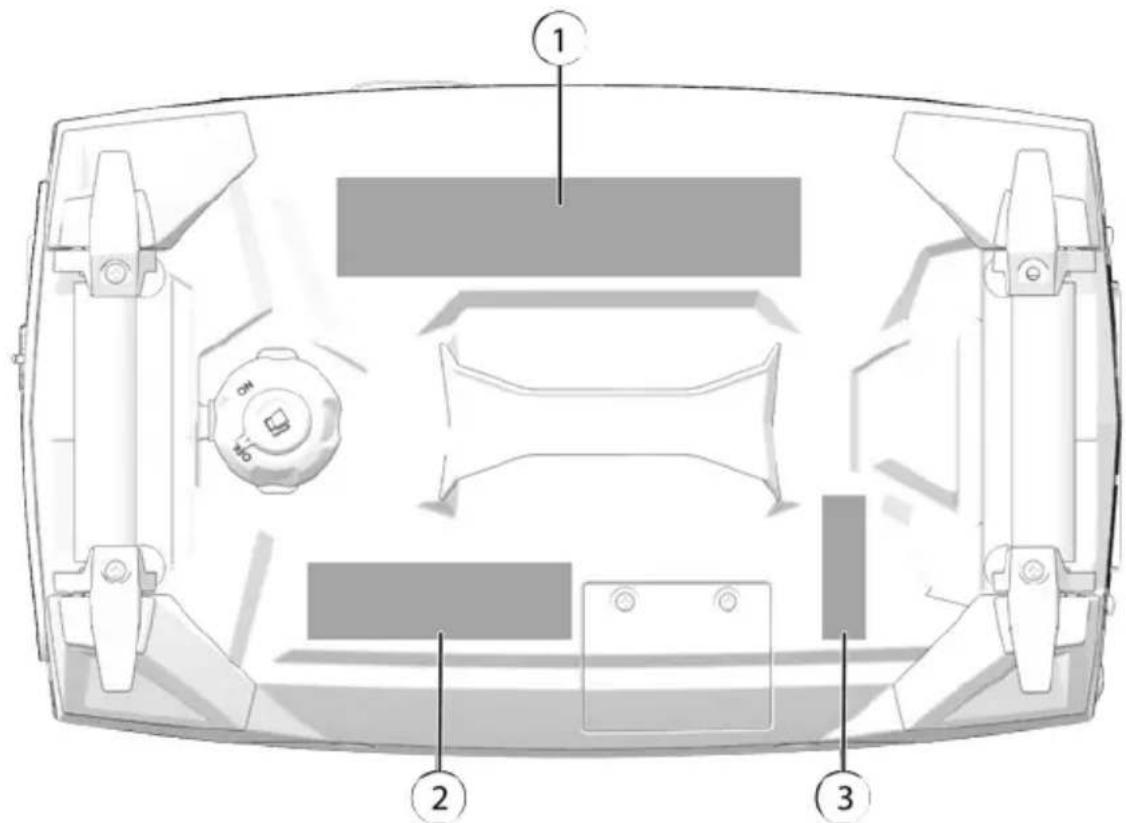
① General Warning
② Carbon Monoxide Danger
③ Hot Exhaust Caution
GENERAL WARNING
The general warning is located on the top side of the generator near the fuel volume indicator.

WARNING
Improper generator use can result in SEVERE INJURY or DEATH. Read the owner's manual. Follow all instructions and warnings.
Gasoline is flammable and explosive. Severe burns can result.
ALWAYS stop the engine and let cool down before refueling.
ALWAYS check for fuel leaks and wipe up any spills.
ALWAYS turn the fuel to OFF when not in use.
NEVER handle gasoline indoors. NEVER overfill the fuel tank.
Generator exhaust contains poisonous Carbon Monoxide (CO) vapors.
ALWAYS operate in a well-ventilated area.
NEVER operate in a home, garage, enclosed area near windows, doors, or people.
NEVER operate near flammable objects.

natural_image
Black silhouette of a flame with flame-like patterns (no text or symbols)
natural_image
Abstract black-and-white illustration of a human head with abstract dotted patterns surrounding the body (no text or symbols)Electrocution can result from using generator in rain, snow, near water, with wet hands, or with improper connections.
ALWAYS keep generator and surrounding area dry.
NEVER connect generator to any building without electrical-isolation protection that meets applicable codes and regulations.

CARBON MONOXIDE WARNING
The carbon monoxide warning label is located on the top side of the generator near the fuel level indicator.

DANGER
Using a generator indoors CAN KILL YOU IN MINUTES.
Generator exhaust contains carbon monoxide. This is a poison you cannot see or smell.
NEVER use inside a home or garage. EVEN IF, doors and windows are open.
Only use OUTSIDE and far away from windows, doors, and vents.

natural_image
Simple line drawing of a house with a window and chimney (no text or symbols)
HOT EXHAUST CAUTION
The hot exhaust caution is located on the top side of the gas tank near the 1 volume indicator.

CAUTION
Contacting a hot exhaust system can cause serious burns. Do not touch if generator is or has been running.

natural_image
Silhouette of a hand with fingers extended (no text or symbols)
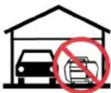
FEATURES AND CONTROLS OVERVIEW
| COMPONENT DESCRIPTION | |
| 1 Control Panel | Contains the switches, buttons, indicator panel, and receptacles for proper operation of the generator. |
| 2 Cord Hooks | Allows for storage of extension cords when generator is not in use. |
| 3 Maintenance Cover | Provides access to inner components for routine maintenance and repair. |
| 4 Feet | Used in combination with folding handle to roll generator across flat surface. |
| 5 Muffler | Reduces noise and emissions from engine combustion. |
| 6 Air Intake | Provides air to cool the engine. |
| 7 Handle | Allows for carry of the generator. |
| 8 Fuel Vent | Allows fuel to flow into the carburetor. |
| 9 Fuel Tank Cap | Provides access to the fuel tank. |
| 10 Fuel Valve Switch | Opens the fuel valve and prevents flooding and dilution. |
| 11 Starter Grip | Causes the recoil starter to crank the engine when pulled. |
CONTROL PANEL
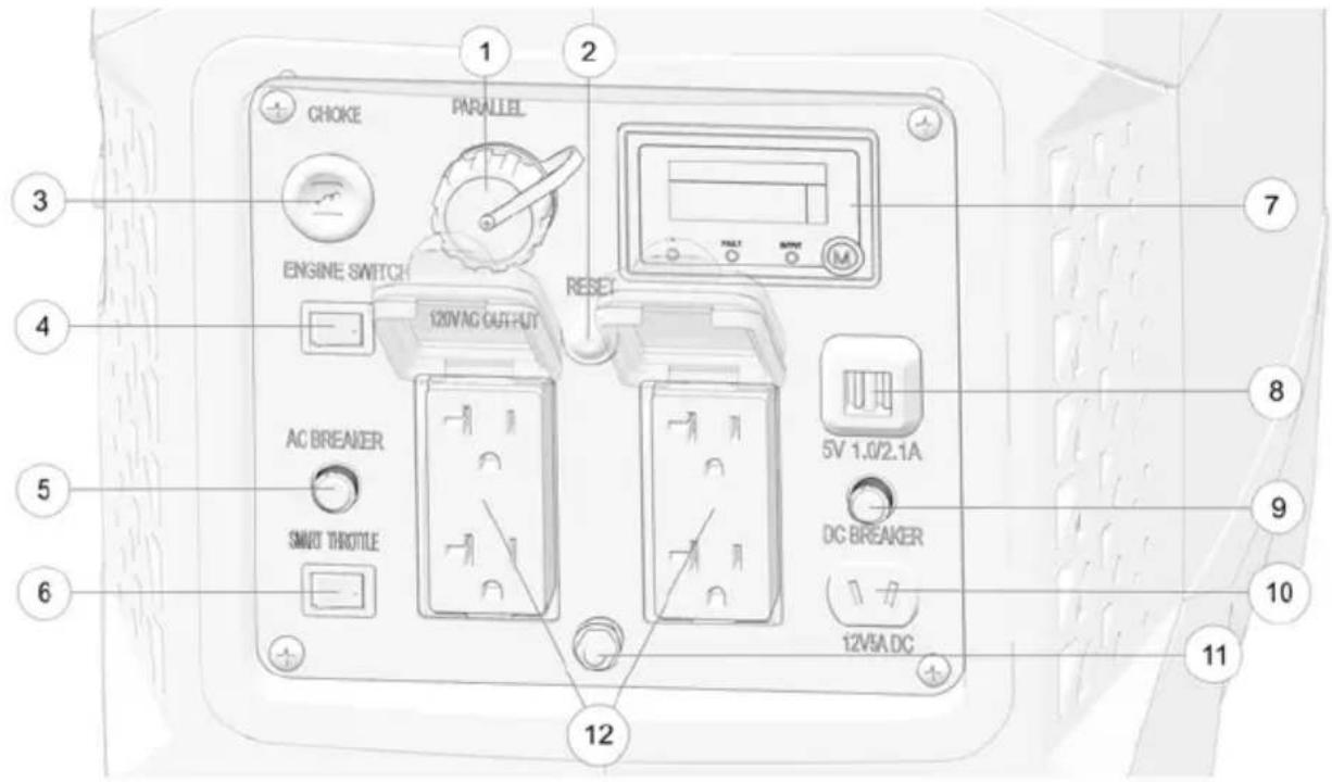
① Parallel Socket
② Overload Reset Button
③ Choke
④ Engine Switch
⑤ AC Circuit Breaker
⑥ SMART Throttle Switch
⑦ Indicator Panel
⑧ 5V USB Ports
⑨ DC Circuit Breaker
⑩ 12V DC Receptacle
⑪ Ground Terminal
⑫ AC Receptacles
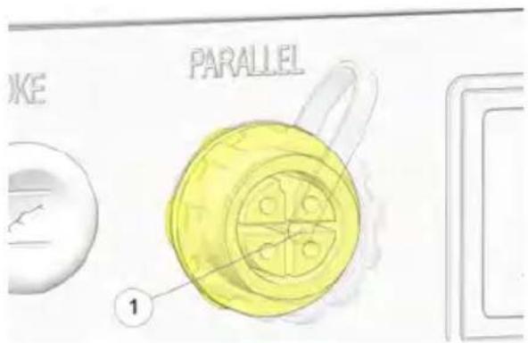
PARALLEL SOCKET
Two Polaris parallel-ready generators can be connected together to increase the total power available to a load, using the parallel socket
The system matches frequency and automatically distributes the load to each generator evenly so neither is overloaded.
Contact your dealer to purchase a POLARIS parallel kit.
OVERLOAD RESET BUTTON
The overload reset button is used in the case of sudden engine shutdown resulting from prolonged engine overload. Should the generator overload, AC power will be cut off but the engine will stay running. Correct the overload condition and then press the overload reset switch on the front panel. AC power will be restored immediately.
In the case of engine overload:
-
Disconnect all electrical appliances.
-
Hold reset button for 1 second to reset the engine.
-
If overload indicator light has turned off and output light has re-illuminated, reconnect electrical appliances.
-
If overload indicator light is still illuminated, set power switch to OFF and check generator.

IMPORTANT
The overload reset button is available for a maximum of 5 times for each full start of the generator. Shut down the generator and restart using power switch in order to refresh number of resets.
CHOKE LEVER
Pulling the choke lever provides proper fuel-starting mixture when the engine is cold. When attempting to start a cold engine, pull the choke lever outward to close. Slowly return the choke to the open position as the engine warms.
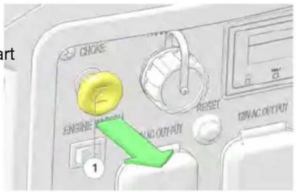
ENGINE SWITCH
Before starting the generator, press the engine switch to the ON position. The engine switch must be in the ON position for the generator to operate. Press the switch to the OF position to shut off the engine.
ENGINE SWITCH
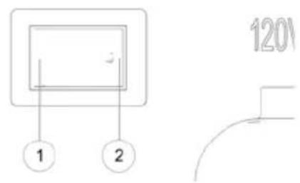
CIRCUIT BREAKERS
The circuit breakers automatically switch OFF if a short circuit or significant overload occurs to one or more of the receptacles.
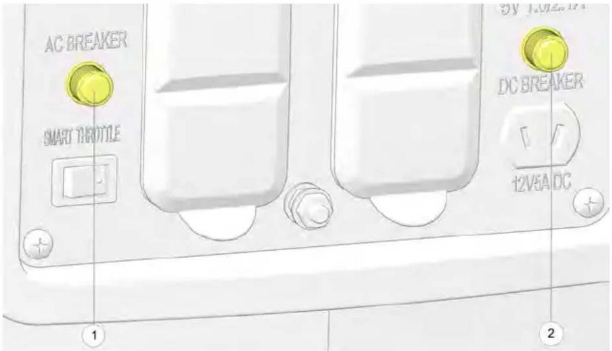
① AC Circuit Breaker
② DC Circuit Breaker
To reset the circuit breaker, push button in to ON position.
NOTICE
Prior to resetting the circuit breaker, check appliances for proper operation and that rated load capacity has not been exceeded.
SMART THROTTLE SWITCH
The SMART throttle switch automatically reduces engine speed when loads are shut off or disconnected. The engine returns to the proper speed to power the electrical load when appliances are turned ON or reconnected.
Press the SMART throttle switch to the OFF position to reduce voltage changes when high electrical loads are simultaneously connected or when using the DC output.
SMART THROTTLE

natural_image
Simple diagram with a crescent moon inside a rectangular frame (no text or symbols)INDICATOR PANEL
| INDICATOR LIGHT DESCRIPTION | ||
 | Low Oil Indicator The low oil alarm system is designed to prevent engine damage caused by an insufficient amount of oil in the crankcase. Before the oil level in the crankcase falls below a safe limit, the low oil alarm system will automatically shut down the engine (the engine switch will remain in the ON position).If the low oil alarm system shuts down the engine the red low oil alarm indicator light will come on when you operate the starter, and the engine will not run. If this occurs, search for any oil leaks. Add engine oil to resume normal operation. See page 58 for oil recommendation. | |
FAULT | Fault / Overload Indicator | If a short circuit occurs in a connected appliance(s), or if the generator is overloaded (produces more than 2800 W), current to the connected appliance will cease, the output indicator (GREEN) will extinguish, and the overload indicator will illuminate RED. |
OUTPUT | Output Indicator The output indicator illuminates GREEN when the generator is in normal operation and producing electrical power at the receptacles. | |
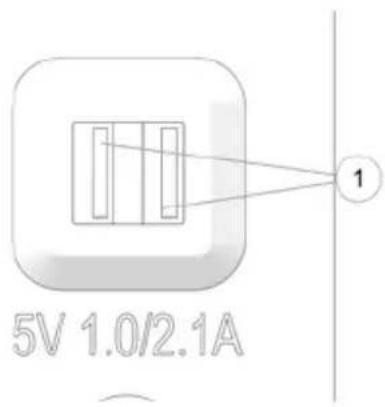
USB PORTS
This generator is equipped with two USB ports①. A total of 3.1A data transfer speed is available at 5 volts.
Each single port can draw the full 3.1A or will be distributed as needed.
DC RECEPTACLE
The DC receptacle charges 12V DC automotive-type batteries. The DC charging output is not regulated.
This receptacle is protected from an overload with a circuit protector. If the DC circuit is overloaded, the protector will open and power to the DC receptacle will cease.
The protector is to the left of the receptacle and is closed by pressing down on the button.

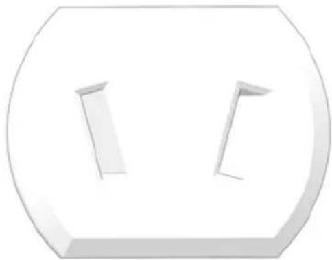
natural_image
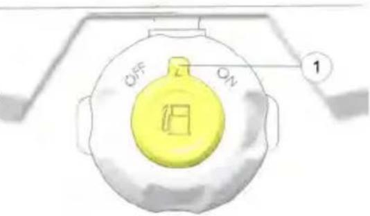
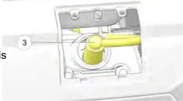
3D-rendered white geometric shape with two vertical cutouts inside, no text or symbols presentFUEL VALVE SWITCH
CAUTION
Always close the fuel valve when the generator is not in use. Forgetting to share the fuel valve increases the risk of flooding, dilution, and hydraulic lock leading to possible engine damage or failure.
The fuel valve switch controls the fuel valve. When the engine is well-cooled at not in use, the fuel valve must be placed in the OFF position to reduce the possibility of fuel leakage.
The switch must be in the ON position to allow the engine to operate.
① ON: opens the fuel valve.
② OFF: closes the fuel valve.
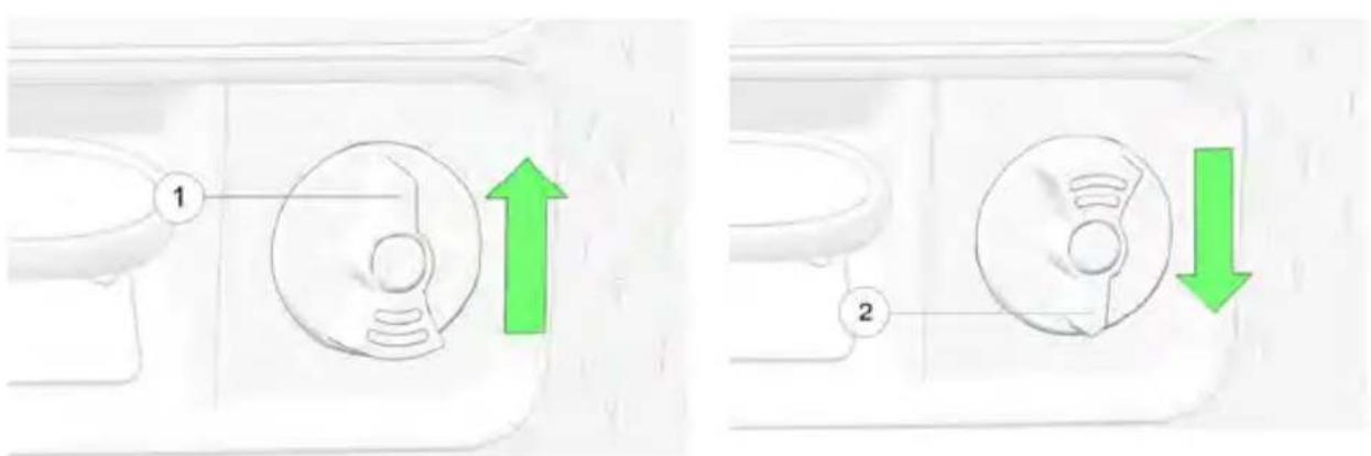
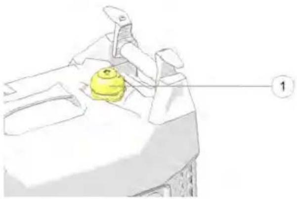
FUEL TANK CAP VENT LEVER

WARNING
Always close the fuel vent after each use and before moving or transporting the generator.
Gasoline is highly flammable and gasoline vapor is explosive under certain conditions. Improper gasoline handling could result in severe energy injury or death.
The gas cap and vent lever are located on the topside of the generator. When the engine is well-cooled and not in use, the fuel tank cap vent lever must be placed in the OFF position to reduce the possibility of fuel leakage. The vent lever must be in the ON position to allow the engine to operate.
STARTER RECOIL GRIP
The starter recoil grip is located on the left side of the generator next to the fuel valve switch. It is used to start the engine by pulling the recoil cord straight out from the frame.
Do not allow starter grip to snap back against the generator. Return it prevent damage to the starter. The starter recoil①gipsuses the recoil starter to crank the engine when pulled.
gently
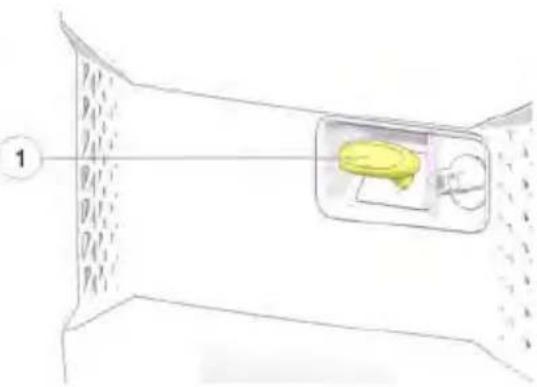
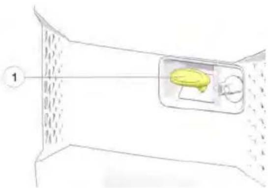
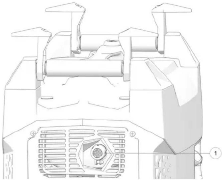
GROUND TERMINAL
The ground terminal ^① is located on the control panel, between the AC receptacles.
The terminal connects to the frame of the generator, metal parts that do not conduct current, and ground terminals of each receptacle.
natural_image
Diagram of a yellow mechanical component with numbered label (1), no readable text or symbols presentNOTICE
Consult a qualified electrician, electrical inspector, or local agency having jurisdiction for local codes or ordinances for the intended use of the generator before using the ground terminal.
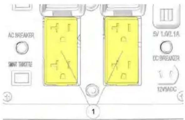
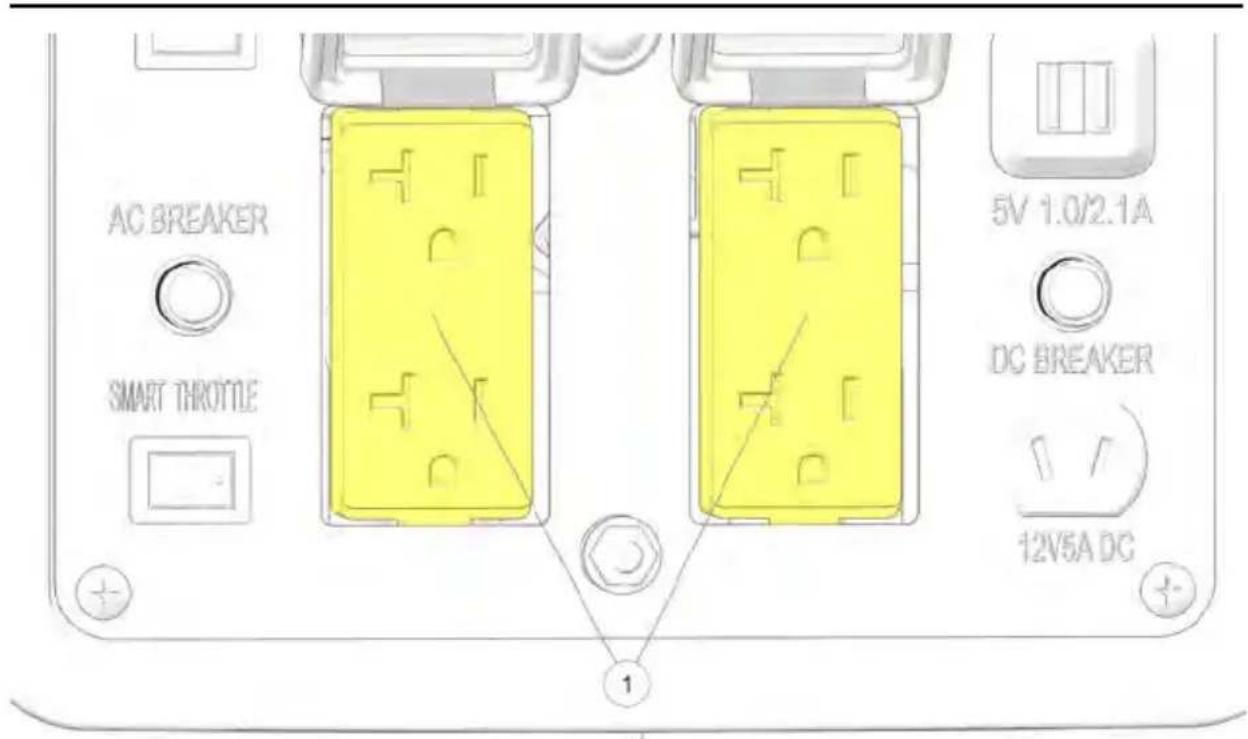
AC RECEPTACLES
The AC receptacles ^① provide four connections for properly rated AC appliances.
FIRST USE INSTRUCTIONS
ADDING ENGINE OIL
NOTICE
This engine uses SAE 5W-30 generator engine oil. Failure to use the recommended 4-stroke engine oil may result in engine damage, see the Specifications section for oil capacity.
- Place generator on flat, level surface. Remove the maintenance cover.
- Remove the oil filler cap / dipstick.
- Fill the engine crankcase with the specified amount.
natural_image
3D rendering of a red spray bottle inserted into a white industrial machine component (no visible text or symbols)-
Insert the dipstick into the filler neck, without screwing it in.
-
Remove the dipstick and verify that the oil level is at the upper limit. Add additional oil and inspect the level as needed until the upper limit has been reached.
-
Re-install the dipstick. Use a clean shop rag to clean any spilled oil.
-
Re-install the maintenance cover.
FUEL
FUEL RECOMMENDATION
Polaris recommends the use of 87 octane fuel or higher.
WARNING
Gasoline is highly flammable and explosive and can cause serious injury or death. Stop the engine and keep heat, sparks, and flame away. Handle fuel only outdoors. Wipe up spills immediately.
CAUTION
Never use stale or contaminated gasoline or an oil /gasoline mixture. Avoid getting dirt or water in the fuel tank.
Do not spill fuel when filling the fuel tank. Damage caused by spilled fuel is not covered under warranty. Spilled fuel is a fire hazard, causes environmental damage, and can damage paint and plastic. Wipe up spills immediately. Do not fill above bottom of strainer.
Refuel in a well ventilated area before starting the engine. If the engine has been running, allow it to cool.
Never refuel the engine inside a building where vapors may reach flames or sparks. Keep fuel vapors away from electrical appliances.
CAUTION
Do not use fuel containing more than 10% ethanol. If the content of ethanol exceeds the specified limits, it may cause starting or performance problems. It may also damage metal, rubber, and plastic parts of the fuel system. Do not use gasoline containing methanol. Damage due to ethanol or methanol is not covered under warranty.
IMPORTANT
Operating the generator with an obstructed fuel system will result in serious engine damage. Perform maintenance as recommended.
Thoroughly read “Safety” section and all safety information when handling fuel. In order to insure the optimum output and the maximum service life of the generator, the generator should run at a 50% load for the first 20 hours.
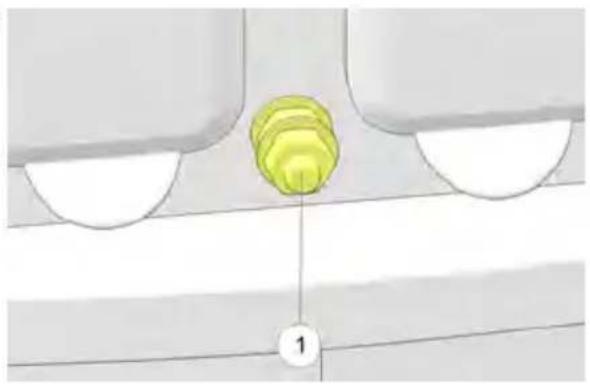
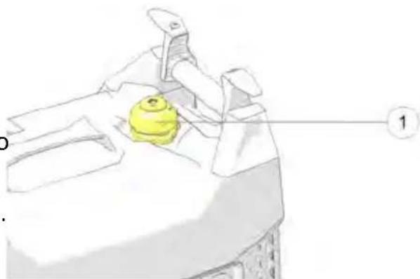
ADDING FUEL
WARNING
Gasoline is highly flammable and gasoline vapor is explosive under certain conditions. Improper gasoline handling could result in severe injury or death. Always use caution when handling gasoline.
- Remove the fuel tank cap.
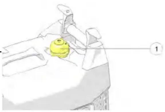
- Fill carefully to avoid spilling fuel on the fuel tank strainer. Do not overfill the fuel tank (there should be no fuel above the upper limit mark).
natural_image
Illustration of a yellow object on a mechanical device with a numbered label (1) pointing to it, no readable text or symbols present.WARNING
Do not overfill. Fuel overflow may spill onto a hot engine and result in fire or explosion.
- Tighten fuel tank cap securely.
- Position fuel switch and fuel vent to OFF for storage or ON to operate the generator.
- Move generator away from fueling source and site before starting engine.
Gasoline is highly flammable and explosive and can cause serious injury or death. Stop the engine and keep heat, sparks, and flame away. Handle fuel only outdoors. Wipe up spills immediately.
CAUTION
Failure to perform the recommended pre-operation inspections could result in minor or moderate injury or property damage. When inspection reveals the need for adjustment, replacement, or repair, perform service promptly or visit your authorized Polaris dealer for assistance.
CAUTION
If the engine has been running, the muffler will be very hot. Allow the cool before servicing.
muffler t
IMPORTANT
Always perform the recommended pre-operation inspections before each and when removing the generator from storage.
use
| ITEM REMARKS PAGE | |
| Engine Oil Check and add oil, as needed. See page 35 | and page 60. |
| Fuel Level Check the fuel level and refuel, as needed. | See page 39. |
| Exhaust System | Inspect the exhaust system for leakage.Tighten or replace gasket, as needed. See page 66. |
| Carburetor Inspect choke knob operation. See page 29. | |
| Level Ground Ensure the generator is resting on a level surface to prevent spills or tipover. | - |
| Grass and Leaves | Remove grass, leaves, and other flammable material or debris, especially near the HOT exhaust system. See page 17. |
OPERATION
SAFE OPERATING PRECAUTIONS
REFUELING

WARNING
Gasoline is highly flammable and explosive and can cause serious injury or death. Stop the engine and keep heat, sparks, and flame away. Handle fuel only outdoors. Wipe up spills immediately. Thoroughly read the Safety chapter of this manual before handling fuel.

CAUTION
Do not spill fuel when filling the fuel tank. Damage caused by spilled fuel is covered under warranty. Spilled fuel is a fire hazard, caused environmental damage, and can damage paint and plastic. Wipe up spills immediately. Do n fill above bottom of strainer.
Refuel in a well ventilated area before starting the engine. If the engine has been running, allow to cool before refueling.
Never refuel the engine inside a building where vapors may reach flames or sparks. Keep fuel vapors away from electrical appliances.
Do not overfill the fuel tank (there should be no fuel in the filler neck). After refueling, make sure the fuel filler cap is closed properly and securely.
To safely refuel the gas tank, perform the following steps.
- Remove fuel tank cap ^① .
- Fill carefully to avoid spilling fuel or exceeding the bottom of the fuel tank strainer.
- Securely tighten fuel tank cap.
- Before starting the generator, move generator away from the fueling site and fuel source.
natural_image
Illustration of a yellow object on a white surface with a numbered label (1) pointing to it, no text or symbols present.STARTING THE ENGINE
! DANGER
Never operate a generator indoors. Engine exhaust contains carbon monoxide, an odorless, colorless gas that can kill you within minutes. Always use this generator outdoors in a well-ventilated area.
WARNING
Before starting the engine, take the following precautions:
- Ensure the generator is away from the fueling source.
- The generator will vibrate during operation. Place the generator in a dry location and on a flat, level surface.
- Unplug all power cords and extension cords from the generator.
-
Perform an oil, fuel, and air filter check.
-
Open the fuel vent.
- Turn the fuel valve switch to ON.
- Press the engine switch to ON.
- For a cold engine start, pull out the choke lever to CLOSE position. To restart a warm engine, leave the choke lever in OPEN.
- Lightly pull the starter recoil gmp until resistance is felt. Then, pull firmly out.
natural_image
Diagram of a container with a yellow object inside, showing internal flow or movement (no text or symbols)STOPPING THE ENGINE
NOTICE
Continually stopping the generator with a load applied can lead to damage of the control module.
In case of emergency, turn ignition switch to OFF position to stop the engine. Under normal conditions, perform the following procedure:
- Shut off or disconnect all appliances connected to the generator.
- Press engine switch to OFF.
- Turn fuel valve switch to OFF.
- Turn fuel vent to OFF.
AC OPERATION
WARNING
Before connecting a device or power cord to the generator, ensure it is in good condition. Faulty appliances or power cords can create a potential for electrical shock.
If an appliance begins to operate abnormally, becomes sluggish, or suddenly stops, immediately shut it off. Disconnect the appliance and determine whether the problem is the appliance or if the rated load capacity of the generator has been exceeded.
Ensure the combined electrical rating of the device or appliance does not exceed the maximum allowed by the generator. Never exceed the maximum power rating of the generator. Do not exceed the current limit specified for an one receptacle. Power levels between rated and maximum may be used for more than 30 minutes.
IMPORTANT: Before connecting a device or power cord to the generator, ensure the device or cord is in good condition and electrical rating does no exceed the maximum amount allowed by the generator.
- Start engine. See page 40 for additional instruction.
- Confirm the desired appliance is switched off. Then plug the appliance or extension cord into one of the AC receptacles
- Turn on the appliance.
| NOTICE |
| Should the generator's maximum load of 25 amps be exceeded, the protection device will trip and cut all current to the receptacles. The end continue to run.Correct the load by unplugging all appliances from the receptacles and press-in the circuit protector button to reset, followed by Overload Reset button. AC power will be restored immediately. |
AC CAPACITY
| MODEL MAX POWER | RATED POWER | |
| P2000i 1600 W 2000 W |
| NOTICE |
| In case of substantial overloading, the electronic circuit protector will act slightly overloading the generator or running at maximum power operation minutes) may not switch the circuit ON, but will shorten the service life generator. |
Consider total power requirements of all connected devices. Appliance and power-tool manufacturers typically list rating information near the model or serial number.
After plugging in a device, allow the generator to stabilize before plugging in additional items. Always consider generator capacity before plugging in any device.
Typical wattages are listed in the table below. Before plugging any device into the generator, verify the manufacturer-listed wattage on the device.
WATTAGE REFERENCE TABLE
| DEVICE RUNNING (RATED) | WATTS ADDITIONAL STARTING(SURGE) WATTS | |
| Table Saw / Radial Arm Saw 10" | -2000 2000 | |
| Space / Wall Heater 1800 0 | ||
| Central Air Conditioning 1500 | 4500 | |
| Circular Saw - 7 1/4" 1400 2300 | ||
| Hair Dryer 300 - 1200 0 | ||
| Sump Pump - 1/2 HP | 1050 2200 | |
| Microwave Oven - 100 Watt | 1000 1400 | |
| Coffee Maker | 1000 0 | |
| Garage Door Opener 1/2 HP | 875 | 2350 |
| Personal Computer w/ 17" Monitor | 800 | 0 |
| Refrigerator | 400 - 800 | 2200 |
| Dehumidifier | 650 | 800 |
| Color Television - 27" | 500 | 0 |
| Electric Drill - 3/8", 4 amps | 440 | 600 |
| Paint Sprayer | 360 | 1080 |
| Radio | 300 | 300 |
| Oven | 60 | 7500 |
| Light Bulb - 75 Watt | 75 | 0 |
POWER MANAGEMENT EXAMPLE
| DEVICE RUNNING (RATED) | WATTS ADDITIONAL STARTING(SURGE) WATTS |
| Radio 300 300 | |
| Personal Computer w/ 17" Monitor | 800 0 |
| Light Bulb (75 W) 75 0 |
1175 = Total Running (Rated) Watts
300 = Additional Starting (Surge) Watts
1475 = Total Generator Output Required

CAUTION
Ensure the combined electrical rating of the powered device(s) do not exceed the maximum output allowed by the generator. Never exceed the maximum power rating of the generator. Power levels between rated and maximum may be used for no more than 30 minutes.
DC OPERATION
The DC Receptacle on this generator is designed to charge 12V DC batteries. It is not designed to operate DC motors.

CAUTION
This generator is not designed to operate DC motors. The DC charging output is not regulated. The DC receptacle should only be used for charging 12V DC batteries. Output voltage is 15-30V.
The DC output is to be used to charge batteries only. Serious damage to the stator windings can occur if connected to a DC motor or transformer.
BATTERY CHARGING
WARNING
The battery emits explosive hydrogen gas during normal operation. A spark of flame can cause the battery to explode with enough force to kill or cause serious injury. Wear protective clothing and eye protection when charging a battery. Failure to adhere to these safety precautions could lead to severe injury or death.
Battery posts, terminals, and related accessories contain lead and lead components. Wash hands after handling.
To prevent the possibility of creating sparks near the battery, connect the charging cable first to the generator then to the battery. Disconnect the cable first at the battery.
The battery contains sulfuric acid (electrolyte). Contact with skin or eyes may cause severe burns. Wear protective clothing and a face shield. If electrolyte gets on your skin, flush with water. If electrolytes get in your eyes, flush with water for at least 15 minutes and call a physician.
Electrolyte is poisonous. If swallowed, drink large quantities of water or milk and follow with milk of magnesia or vegetable oil and call a physician. Keep of reach of children.
CONNECTING THE BATTERY CHARGING CABLE
CAUTION
Do not start the vehicle while the battery charging cable is connected and the generator is running. The vehicle's charging system or the generator may be damaged.
-
Disconnect the ground cable from the negative (-) battery terminal, followed by the positive (+) cable.
-
Plug the battery charging cable into the DC receptacle.
-
Connect the red lead of the battery charging cable to the positive (+) battery terminal and then the black lead to negative (-) battery terminal.
natural_image
3D-rendered geometric shape with two internal cutouts, no text or symbols presentCAUTION
Do not reverse the charging cables or serious damage to the generator battery may occur.
and/c
- Ensure the SMART throttle switch is OFF.
- Start the generator.
DC CIRCUIT OVERLOAD
The DC receptacle is protected from an overload with a circuit protector. If the DC circuit is overloaded, the protector will trip and power to the DC receptacle will cease.
If the circuit protector keeps tripping, discontinue charging and see your authorized Polaris generator dealer.
NOTICE
The circuit protector does not prevent overcharging of the battery.
DISCONNECTING THE BATTERY CHARGING CABLE
- Stop the generator.
- Disconnect the black lead of the battery charging cable from the negative (-) battery terminal and then the lead from the positive (+) battery terminal.
- Unplug the battery charging cable from the DC receptacle.
- Connect the vehicle battery ground cable to the negative (-) battery terminal.
AIR CONDITIONING OPERATION
Bring the generator to a normal operating temperature before applying the air conditioning load. Always allow a two-minute wait period when manually cycling an air conditioner off and on.
A longer wait period may be required under unusually hot weather conditions. other loads should be turned off until the air conditioner has started and is performing normally.
Before applying an air conditioning load, ensure that your generator is rated to handle to the load. Use the table below and the formula included in the AC Operation chapter for reference.
| AC OUTPUT RUNNING (RATED) WATTS ADDITIONAL STARTING(SURGE) WATTS | |
| Window AC - 10,000 BTU 1200 3600 | |
| Window AC - 12,000 BTU 3250 9750 | |
| Central AC - 10,000 BTU 1500 4500 | |
| Central AC - 24,000 BTU 3800 11400 | |
| Central AC - 40,000 BTU 6000 18000 | |
NOTICE
Follow the air conditioner manufacturer's instructions for starting and restarting for proper operation. Some air conditioner manufacturers offer a start capacitor as an extra cost option.
The lack of a start capacitor can cause the air conditioner to draw too high starting current and overload the generator. Contact your air conditioner dealer if you consistently have problems starting your air conditioner with the generator.
STANDBY POWER
CONNECTIONS TO A BUILDING ELECTRICAL SYSTEM
WARNING
Improper connection to a building electrical system can allow current from the generator to back feed into the utility lines. Such back feed may electrocute utility company workers or others who contact the lines during a power outage. Additionally, the generator may explode, burn, or cause fires when utility power is restored. Consult the utility company or a qualified electrician prior to making any power connections.
Connections for standby power to a building's electrical system must be made by a qualified electrician and must comply with all applicable laws and electrical codes. Improper connections can allow electrical current from the generator to back feed into the utility lines.
Such back feed may electrocute utility company workers or others who contact the lines during a power outage; when utility power is restored, the generator may explode, burn, or cause fires in the building's electrical system. Do not connect this generator to an automatic transfer switch. Serious damage to the engine and inverter module may result.
In some areas, generators are lawfully required to be registered with local utility companies. Check local regulations for proper registration and usage procedures.
GROUND SYSTEM
This generator is equipped with a system ground to prevent electrical shock from faulty appliances.
To ground this generator, perform the following steps:
-
Ensure engine is OFF and fuel valve switch is OFF.
-
Using a mallet, drive a grounding rod 4 ft. into the ground.
-
Wrap a length of bare copper grounding wire tightly around the grounding rod or use a grounding clamp.
-
Slightly loosen bolt on ground terminal. Allow enough space to wrap copper wire.
-
Using the other end of the copper wire, tightly wrap the wire around the terminal.
SYSTEM REQUIREMENTS
There may be federal or state Occupational Safety and Health Administration (OSHA) regulations, local codes, or ordinances that apply to the intended use the generator. Please consult a qualified electrician, electrical inspector, or the local agency having jurisdiction.
If the generator is used at a construction site, there may be additional regulatory requirements.
HIGH ALTITUDE USE
CARBURETOR MODIFICATION
NOTICE
When carburetor has been modified for high altitude operation, the air-fuel mixture will be too lean for low altitude use and may cause engine damage. At high altitude, the standard carburetor air-fuel mixture will be excessively rich. Performance will decrease and fuel consumption will increase. A very rich mixture will also foul the spark plug and cause hard starting. Operation at an altitude different than that which this engine was certified, for extended periods of time, may increase emissions.
High altitude operation can be improved by specific modifications to the carburetor. If always operating the generator at altitudes above 3000 feet (915 meters), have an authorized Polaris servicing dealer perform the carburetor modification. The engine will meet each emission standard throughout its life when operated at high altitude with the carburetor modifications for high altitude operation.
With the carburetor modification, engine horsepower will decrease by about 3.5% for every 1000 feet (300 meters) increase in altitude. The effect of altitude on horsepower will be greater if no carburetor modification is made.
CAUTION
Operation of the generator at an altitude lower than the carburetor is jetted for may result in reduced performance, overheating, and serious engine damage caused by an excessively lean air/fuel mixture. Be sure to have any modification reversed at lower altitudes.
ALTITUDE KITS
For added convenience, POLARIS offers high altitude kits which optimize performance and fuel consumption at various altitude ranges. For installation instruction, see page 61.
| MODEL PART | NUMBER DESCRIPTION | |
| P2000i 2884865 | K-HIGH,ALT,3-8K,P2000I | |
| P3200iE 2884866 | K-HIGH,ALT,3-8K,P3200IE | |
| P5500 / P6500 | 2884867 K-HIGH,ALT,3-8K,P5500/6500 | |
Exhaust gas contains carbon monoxide, nitrous oxide (NOx), and hydrocarbons. It is very important to control the emissions of NOx and hydrocarbons as they are a major contributor to air pollution. Carbon monoxide is a poisonous gas. The emission of fuel vapors is a source of pollution as well. The generator engine utilizes a precise air-fuel ratio and emission control system to reduce the emissions of carbon monoxide, NOx, hydrocarbons, and evaporative fuel emissions.
Polaris utilizes appropriate air-fuel ratios and other emissions control systems to reduce the emissions of carbon monoxide, oxides of nitrogen, and hydrocarbons. In addition, Polaris fuel systems utilize components and control technologies to reduce evaporative emissions.
U.S. AND CALIFORNIA CLEAN AIR ACTS
Your engine has been designed to meet current Environmental Protection Agency (EPA) and the California Air Resources Board (CARB) clean air standards. The regulations dictate that the manufacturers provide operation and maintenance standards regarding the emission control system. Tune up specifications are provided in the Maintenance section. Adherence to the specified maintenance instructions is essential for your engine to meet the emission control standards.
ALTERATIONS
Altering the emission control system may increase emissions beyond the legal limit. Some possible alterations are removal or alteration of any part of the intake, fuel, or exhaust systems.
PROBLEMS AFFECTING EMISSIONS
If aware of any of the following, have the engine inspected and repaired by a authorized Polaris dealer:
- Hard starting or stalling after starting
- Rough idle
- Shut down or backfire after applying an electrical load
• Afterburning (backfiring) - Black exhaust smoke or high fuel consumption
REPLACEMENT PARTS
The emission control system on the engine was designed, built, and certified to conform to applicable emission regulations. We recommend the use of Polaris Genuine parts whenever maintenance is performed. These original-design replacement parts are manufactured to the same standards as the original parts. The use of replacement parts that are not of the original design and quality may impair the effectiveness of the emission control system.
Aftermarket part manufacturers assume the responsibility that the part will not adversely affect emission performance. The manufacturer or re-builder of the part must certify that use of the part will not result in a failure of the engine to comply with emission regulations.
MAINTENANCE
IMPORTANCE OF MAINTENANCE
Good maintenance is essential for safe and economical operation. Proper maintenance will also help reduce air pollution. Always follow the recommendations for inspection and maintenance as specified in this manual.

WARNING
Improper maintenance, or failure to fix problems prior to operation, could lead to generator malfunction resulting in serious injury or death.
The following chapter includes a periodic maintenance schedule, including proper inspection and maintenance procedure. The maintenance schedule applies to normal operating conditions. This maintenance is essential to the longevity of your generator.
Any qualified repair shop or person may maintain, replace or repair the emission control devices or systems on your generator. POLARIS also recommends POLARIS parts for emissions-related service, however equivalent parts can be used.
IMPORTANT
It is a potential violation of the Clean Air Act if a part, supplied by an aftermarket parts manufacturer, reduces the effectiveness of the generator's emission controls. Tampering with emission controls is prohibited by federal law.
Owners are responsible for performing the scheduled maintenance identified in this owner's manual. Careful periodic maintenance will help keep your generator in safe, reliable condition. Inspect, clean, lubricate, adjust and replace parts as necessary. Other, more difficult tasks, require special tools and expertise provided by an authorized Polaris technician or other qualified mechanic.
If the generator is operated under unusual conditions, such as sustained high load or high temperature, or dusty conditions, consult the servicing dealer for applicable recommendations.
All necessary replacement parts and labor incurred, with the exception of authorized warranty repairs, become the responsibility of the registered owner. If, during the course of the warranty period, part failures occur as a result of owner neglect in performing recommended regular maintenance, the cost of repairs are the responsibility of the owner.
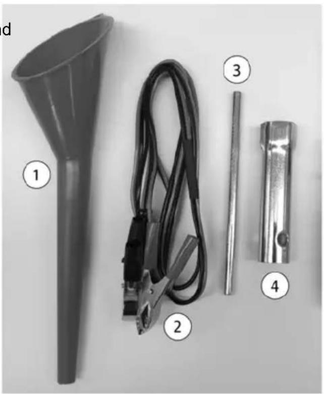
TOOL KIT
This generator is packaged with a tool kit to help with basic repair and maintenance.
natural_image
Black-and-white photo of four electronic components: a funnel, coiled cable, clamp, and a cylindrical device (no text or symbols visible)| REF. NO. | TOOL DESCRIPTION QUANTITY | |
| 1 | Oil Fill Funnel 1 | |
| 2 | 12V DC Cable 1 | |
| 3 | Spark Plug Wrench Handle 1 | |
| 4 | Spark Plug Wrench 1 |
MAINTENANCE SAFETY
CAUTION
After any maintenance is performed, wash skin immediately using soap and clean water as exposure to lubricant may cause skin irritation.
WARNING
Personal safety is critical when attempting to service the generator. Improperly installed or adjusted components can make the generator unstable or dangerous. Improperly installed electrical components can cause engine or electrical systems failure. In either event, damage or serious injury could result. If you do not have the time, tools, and/or expertise necessary to complete a procedure properly, please see your Polaris dealer or other certified technician for service.
Failure to correct a problem before operation and improper maintenance can cause a malfunction resulting in injury or death. Always follow the inspection and maintenance schedules and requirements in this manual.
The following important safety precautions cannot warn of every possible hazard from maintenance. The decision to perform a given task must be evaluated by the individual performing it.
PERIODIC MAINTENANCE
Prior to performing any maintenance on your generator,
- Always stop the engine before servicing. Disconnect all devices and extension cords to avoid receiving an electrical shock.
- Periodic checks and maintenance are very important for keeping the generator in good condition.
- Inspect, clean, lubricate, adjust, and replace parts as necessary. When inspection reveals the need for replacement parts, use Polaris Genuine parts available from your Polaris dealer.
- Before beginning any maintenance procedure, read the instructions for the entire procedure. During some procedures, potentially hazardous products may be used. Always follow the instructions and warnings on the product packaging.
PERIODIC MAINTENANCE CHART
| ITEM REMARKS PRE- | OPERATION CHECK (DAILY) | INITIAL 1 MONTH OR 20 HOURS | EVERY 3 MONTHS OR 50 HOURS | EVERY 6 MONTHS OR 100 HOURS | EVERY 12 MONTHS OR 300 HOURS | |
| Spark Plug | Check condition. Adjust gap and clean. Replace as needed. | X | ||||
| Spark Arrester | Clean the carbon deposits. | X | ||||
| Engine Oil | Check the oil level. | X | ||||
| Replace oil. | X | X | ||||
| Air Filter | Check filter. | X | ||||
| Clean. Replace as needed. | X_2 | |||||
| Fuel Sediment Cup | Clean. | X | ||||
| Fuel Tank and Strainer | Clean. | X_3 | ||||
| Valve Clearance | Check and adjust when engine is cold. | X_3 | ||||
| Fuel Line | Check fuel line for twists, cracks, or damage. Replace as needed. | Every 2 years (Replace as necessary) _3 | ||||
| 1. Log hours of operation to determine proper maintenance.2. Service more frequently when used in dusty conditions.3. These items should be serviced by an authorized Polaris dealer unless the owner has the tools and is mechanically proficient. Refer to the Polaris Service manuals. | ||||||
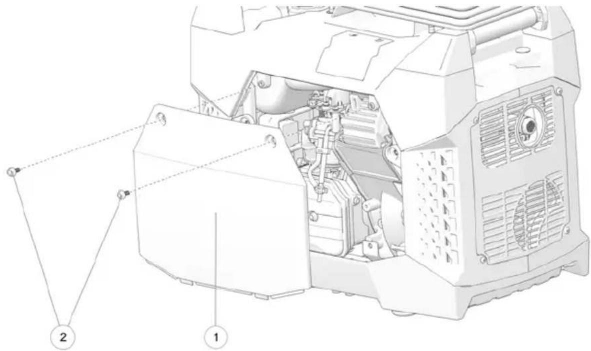
REMOVING THE MAINTENANCE COVER
Use the following steps to remove the generator maintenance covered gain access to the inner components. Before performing any maintenance, the engine switch should be positioned to OFF.
-
Position the engine switch, fuel valve switch, and fuel vent to OFF.
-
Remove the two screws from the maintenance cover.
-
Remove the cover to expose the inner components of the generator.
-
Perform maintenance as needed.
-
Upon completion of maintenance, replace cover by inserting the bottom edge into the grooves and replacing the two screws.
-
Position the ignition switch to the ON position to allow generator operation.
FUEL SYSTEM
WARNING
Gasoline is highly flammable and explosive, and can cause serious injury or death. Stop the engine and keep heat, sparks, and flame away. Handle fuel only outdoors. Wipe up spills immediately.
FUEL LINE INSPECTION
Inspect the fuel line to ensure absence of twists, cracks, and / or damage. Replace as needed.
GAS TANK STRAINER
- Remove the fuel tank cap.
- Remove the fuel tank strainer from the fuel tank.
- Remove any foreign objects or debris from the fuel tank strainer.
- Inspect the fuel tank strainer for damage. Replace as needed.
- Install the fuel tank strainer into the fuel tank.
- Securely tighten the fuel tank cap.
- Position the fuel valve switch OFF for storage or transport, or ON to run the generator.
ENGINE OIL
OIL RECOMMENDATION
Oil Recommendation POLARIS 5W-30 Generator Oil
Oil directly affects performance and service life. Use a 4-stroke automotive detergent oil, see page 75 for recommended oil. Other viscosities may be used when the applicable average temperature is within the recommended range.
The SAE oil viscosity and service category are in the API label on the oil container. Polaris recommends the use of API service category "SJ" or later, equivalent oil.
OIL LEVEL INSPECTION
CAUTION
Failure to use the proper 4-stroke engine oil may result in engine damage.
Using non-recommended oil may cause serious engine damage. Never substitute or mix oil brands.
Inspect the oil level before each use with the engine stopped and the genera on a level surface.
- Remove the oil filler cap / dipstick and wipe it clean.
- Insert the dipstick into filler neck, screwing it in, to inspect the oil level.
- Remove the dipstick and verify that the oil is at the upper limit. Add additional oil and inspect the level as needed until the upper limit has been reached.
- Re-install the dipstick. Use a clean shop rag to clean any spilled oil.
NOTICE
- Do not tilt generator when adding engine oil. This could result in overfilling and damage to the engine.
- Use high quality 4-stroke engine oil, certified to meet or exceed API standard SG, SF, SAE raings with strong detergents. Using non-detergent o 2-stroke oil could shorten the engine's working life.
- Do not mix different engine oils.
- Handle and store the engine oil with care, avoid getting dirt or dust into the engine oil.
- Before the engine oil falls below the safety margin, the low oil alert system automatically shut off the engine. The low oil light (RED) will illuminate.
- To avoid the inconvenience of unexpected engine shutdown, check oil before each use.
OIL CHANGE

WARNING
Oil may be hot. Do not allow hot oil to come into contact with skin, as serious burns may result.
NOTICE
Drain the oil while the engine is warm to assure rapid and complete draining.
IMPORTANT
Improper disposal of engine oil can be harmful to the environment and is unlawful. Properly dispose of used oil.
- Start the engine and allow it to run for a few minutes. Stop the engine.
- Position the fuel valve switch and fuel vent to OFF.
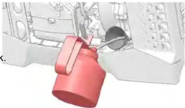
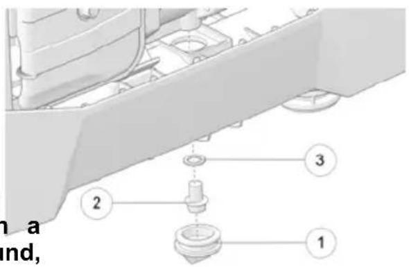
- Elevate the generator several inches to allow access to the drain bolt under the bottom tray.
- Remove the oil filler cap / dipstick.
-
Place a drain pan under the generator.
-
Remove the rubber grommet from the bottom of the tray.
-
Unscrew drain bolt② and remove the washer③.
-
Drain the used oil into a sealed container and take it to a recycling center. Do not discard the oil in a trash can, dump it on the ground, or pour it down the drain.
- Re-install the oil drain bolt and replace the rubber plug.
10.Optional: Place provided funnel into fill valve.
- Fill oil to the high limit mark on the dipstick. Ensure that the oil level does rise past the threading of the cap.
MEASUREMENT
Oil Capacity
13.6 oz (0.4 L)
- Remove funnel and re-install the dipstick.
- Start the engine and let it run for 1 or 2 minutes. Stop the engine and loc leaks.
- Re-check the oil level on the dipstick and add oil as needed to bring the I to the upper mark on the dipstick.
- Re-install the dipstick.
- Wash hands with soap and water after handling used oil.
HIGH ALTITUDE JETS

WARNING
Gasoline is highly flammable and is explosive. You can be burned or seriously injured when handling fuel. Keep heat, sparks, and flame away. Wipe up spill immediately.
NOTICE
| Using the wrong carburetor main jet may cause poor engine performance. If too lean of a main jet is used, severe engine damage may result. |
ALTITUDE KITS
| MODEL PART | NUMBER | DESCRIPTION |
| P2000i 2884865 | K-HIGH,ALT,3-8K | ,P2000I |
| P3200iE 2884866 | K-HIGH,ALT,3-8K | ,P3200IE |
| P5500 / P6500 | 2884867 K-HIGH | ,ALT,3-8K,P5500/6500 |
ALTITUDE JET SPECIFICATIONS
| MODEL ENGINE ALTITUDE JET MARK | |||
| P2000i 79cc | 3000-6000 ft 68 | ||
| 6000-8000 ft 67 | |||
| P3200iE | 208cc | 3000-6000 ft 74 | |
| 6000-8000 ft 73 | |||
| P5500 | 389cc | 3000-6000 ft 103 | |
| 6000-8000 ft 101 | |||
| P6500 420cc | 3000-6000 ft 107 | ||
| 6000-8000 ft 105 | |||
JET INSTALLATION
To change the carburetor main jet, follow this procedure:
- Turn off the fuel supply.
- Access the carburetor drain screw. Drain the fuel from the carburetor into a suitable container.
- Remove the float bowl chamber bolt.
- Remove the main jet from the carburetor.
- Install the correct main for the altitude in which the generator is operating. Do not over-tighten the jet.
- Re-install the float chamber bolt.
- Close carburetor drain screw.
- Turn on fuel supply. Start generator and let engine run for several minutes.
- Turn off generator. Verify there are no fuel leaks.
AIR FILTER

WARNING
Do not use gasoline or low flash point solvents for cleaning. They are flammable and explosive under certain conditions.
NOTICE
An obstructed air filter restricts air flow to the carburetor. To prevent carburetor malfunction, regularly service the air filter. Service more frequently when operating the generator in extremely dusty areas.
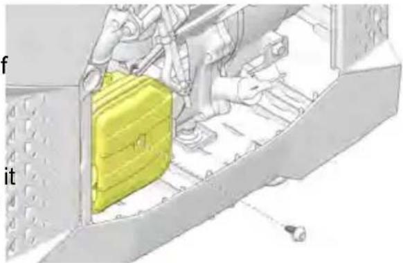
- Remove the maintenance cover.
- Remove the screw from the front of the air box.
- Remove the air filter.
- If the filter is dirty or torn, replace it with a new one. Do not attempt to clean the element.
- Re-install the air filter cover and screw.
natural_image
Illustration of a yellow briefcase on a conveyor belt with a hand operating it (no text or symbols)IMPORTANT
When replacing the filter, ensure that the filter is not pinched between the covers to secure a proper seal.
FOAM FILTERS
If using a foam air filter, follow the steps below to clean the filter before replait it in the air box.
- Submerge the filter in a solution of warm water and household detergent.
- Let the filter soak in the solution for a few minutes and then squeeze out excess water.
- Repeat step 2 several times to ensure the water coming from the filter is clean. Then let the filter dry completely.
- Once dry, pour air filter oil onto the filter and distribute evenly. Be sure to the filter of excess oil.
NOTICE
The use of air filter oil allows the filter to catch even the smallest particles of and dust.
- If at any point during the cleaning process, the filter becomes damaged, the it must be replaced prior to operating your generator.
SPARK PLUG
SPARK PLUG INSPECTION
Using a non-recommended spark plug can result in serious engine damage. Always use recommended spark plugs. Refer to the Specification section for the recommended spark plug type. Always torque spark plugs to the specification.
In order to service the spark plug, the provided spark plug wrench is required.
CAUTION
A hot exhaust system and engine can cause burns. Wear protective gloves when removing a spark plug for inspection.
IMPORTANT
To ensure proper engine operation, the spark plug must be free of deposits and properly gapped. If the engine has been running, allow it to cool before servicing.
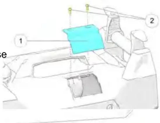
The spark plug can be accessed through the spark plug access at the top of the generator, or by removing the maintenance panel.
- Remove two screws ^② from spark plug access door.
- Remove the spark plug cap.
- Clean any dirt from around the base of the spark plug.
- Using the provided park plug wrench, remove the spark plug.
- Inspect the electrode for wear and carbon buildup. Look for a sharp outer edge with no rounding or erosion of the electrode.
- Inspect spark plug. Replace if electrodes are worn or if insulator is cracked, chipped, or fouled.
- Clean the spark plug with a wire brush if it is to be reused.
natural_image
Mechanical switch component diagram showing a yellow lever and green handle inside a housing (no text or symbols)NORMAL PLUG
The normal insulator tip is gray, tan or light brown. There will be few combustior deposits. The electrodes are not burned or eroded.
This indicates the proper type and heat range for the engine and the service.
WET FOULED PLUG
The wet fouled insulator tip is black. A damp oil film covers the firing end. There may be a carbon layer over the entire nose. Generally, the electrodes are not worn. Fouling may be caused by excessive oil or by frequent short trips, especially in cold weather.
SPARK PLUG REPLACEMENT
IMPORTANT
Prior to replacing the spark plug, complete the inspection steps outlined on page 63.
- Open the maintenance cover.
- Remove the spark plug cap.
- Clean any dirt from around the base of the spark plug.
- Using the provided park plug wrench, remove the spark plug.
natural_image
Mechanical assembly diagram showing a yellow component inserted into a white housing (no text or symbols visible)- Using a wire-type feeler gauge, measure the spark plug electrode gap. If necessary, correct the gap by carefully bending the side electrode.
MEASUREMENT
Spark Plug Gap
0.024- 0.028 in (0.6-0.7 mm)
- Ensure the spark plug sealing washer is in good condition and thread the spark plug in by hand to prevent cross-threading.
- After a new spark plug has been seated by hand, it should be tightened 1, turn with a wrench to compress the sealing washer. If a used plug is being reinstalled, it should only require 1/8 to 1/4 turn after being seated.
- Re-install the spark plug cap and close the maintenance cover.
NOTICE
A loose spark plug can overheat and damage the engine. Over tightening the spark plug can damage the plug threads.
Never use a spark plug with an improper heat range.
SPARK ARRESTER
The spark arrester ^① is located on the end of the muffler.
natural_image
Technical line drawing of a mechanical component with no visible text or symbols
WARNING
Generator exhaust system gets hot enough to ignite some materials and burn skin if touched.
Allow generator and exhaust to cool before performing spark arrestor maintenance.

CAUTION
The spark arrester must be serviced every 100 hours to maintain its efficiency.
Before performing any inspection or maintenance on the battery, ignition switch should be positioned to OFF.
REMOVING THE SPARK ARRESTER
- Remove screw holding the spark arrester to the muffler.
- Pull the end cap off to remove the arrester screen.
- Clean the spark arrestor with a stiff wire brush.
- Replace if the wire mesh is perforated or torn.
- Reinstall screen and cap. Secure cap to the muffler with the screw.
CLEANING AND STORAGE
CLEANING THE GENERATOR

WARNING
Never pour water directly onto the generator or wash it with water. Contact water could result in severe shock or electrocution. Keep generator dry and away from all sources of moisture.
To clean the generator, wipe down with a dry shop rag. Always use clean clo and pads for cleaning and polishing.
If an informational or graphic label becomes illegible or comes off, contact you POLARIS dealer to procure a replacement. Replacement safety labels are provided by POLARIS at no charge.
STORAGE PREPARATION

WARNING
Gasoline is highly flammable and explosive and can cause serious injury. Sto the engine and keep heat, sparks, and flame away. Only handle fuel outdoors. Wipe up spills immediately.
Long-term storage of the generator will require some additional preventative measures to guard against deterioration. If fuel is kept in the generator, run the engine for at least 30 minutes each month to ensure an easy start during the next operation. Be sure the storage area is free of excessive humidity and dust
- If the generator will be stored with fuel, add fuel stabilizer. See page 68.
- If the generator will be stored dry of fuel, drain all fuel and fog the engine prior to storage. See page 68 and page 69.
- Change engine oil. See page 60.
- Remove battery and store in cool, dry location. Use a battery trickle charge to maintain battery charge.
- Clean exterior of the generator with a clean, dry cloth.

WARNING
Do not pour water directly on to the generator or wash it with water.
- Turn fuel valve switch to OFF.
ACCESSING THE FUEL TANK
- Remove the fuel tank cap.
- Remove debris as needed.
- When maintenance is complete, re-install the fuel tank strainer into the fuel tank.
- Securely tighten the fuel tank cap.
natural_image
Diagram of a yellow object on a white surface with a numbered label (1) pointing to it, no readable text or symbols present.STABILIZING THE FUEL

WARNING
A hot engine or exhaust system can cause severe burns and ignite flammable material. Ensure adequate time for cooling before storage or transportation.
This procedure applies if keeping gasoline in fuel tank during storage. Drain the carburetor bowl prior to any storage period longer than 30 days. See page 83 fc suitable fuel stabilizer.
- Access the fuel tank.
- Add a suitable fuel stabilizer.
DRAINING THE FUEL

WARNING
Gasoline is highly flammable and explosive and can cause serious injury or death. Stop the engine and keep heat, sparks, and flame away. Handle fuel only outdoors. Wipe up spills immediately. Do not spill fuel when draining the fuel tank. Spilled fuel is a fire hazard, causes environmental damage, and can cause damage to paint and plastic. Wipe up spills immediately.
Perform this procedure if fuel will NOT be kept in the fuel tank during storage o before transportation.
- Access the fuel tank and remove the gas cap.
- Empty fuel tank into an approved gasoline container. Polaris recommends using a commercially available gasoline hand pump to empty the tank. Do not use an electric pump.
- Re-install gas cap onto the tank and securely tighten.
FOGGING THE ENGINE
- Turn the engine switch to the OFF position.
- Remove the spark plug cap.
- Using the provided park plug wrench, remove the spark plug.
- Pour a tablespoon of clean engine oil into the cylinder. Crank the engine several revolutions to distribute the oil and then reinstall the spark plug.
-
Ensure that the spark plug sealing washer is in good condition and hand-tighten the spark plug to prevent cross-threading.
-
Using a spark plug wrench, carefully tighten the spark plug. Torque the spark plug to specification, see page 63.
-
Slowly pull the starter grip until resistance is felt. At this point, the piston is coming up on its compression stroke and both the intake and exhaust valve are closed. Storing the engine in this position will help protect it from intercorrosion.
-
Re-install the spark plug cap.
-
Cover the generator and store indoors, in a dry, well-ventilated area.
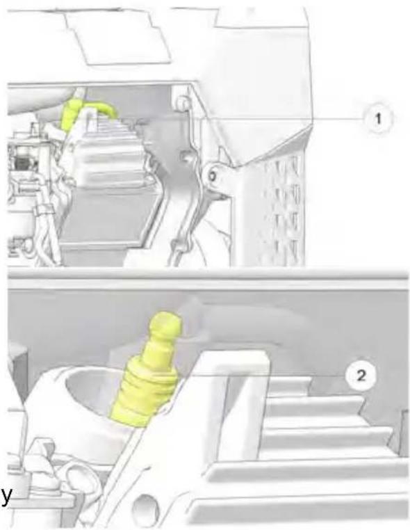
natural_image
Mechanical assembly diagram showing internal components and a yellow component (no text or labels)BATTERY STORAGE
Recharge the battery once a month or use a trickle charger to maintain batter charge. See page 69 for additional instruction.
STORAGE PRECAUTIONS
NOTICE
Do not store the generator outdoors in the cold weather when not in use.
- Select a well-ventilated storage area away from any flame-operated appliance (i.e., furnace, water heater, or clothes dryer). Avoid areas containing a spark producing electric motor, or where power tools are operated.
- Be sure storage area is free of excessive humidity and dust.
-
Place generator on a level surface. Tilting can cause fuel or oil leakage.
-
With the engine and exhaust system cooled, cover the generator to prevent dust contamination. Do not use a plastic sheet as a dust cover. Nonporous covers trap moisture around the generator, promoting rust and corrosion.
- Position fuel tank cap vent lever to OFF to reduce leakage possibilities.
REMOVAL FROM STORAGE
NOTICE
If the cylinder was coated with oil during storage preparation, the engine may smoke briefly at startup. This is normal.
- Perform all steps from in the Pre-Operation Inspection.
- If fuel was drained during storage preparation, fill tank with fresh gasoline. See page 39. If gasoline is stored in a container, ensure the gasoline is fresh. Gasoline oxidizes and deteriorates over time, causing hard starting.
TRANSPORTING THE GENERATOR

WARNING
A hot engine or exhaust system can cause severe burns and ignite flammable material. Ensure adequate time for cooling before storage or transportation. When operating or transporting the generator, be sure it is kept upright. If the generator tilts, fuel may leak. Be sure the fuel tank cap is tight during transportation.

CAUTION
Transporting the generator with gasoline in the fuel tank is prohibited. Transporting the generator with fuel in the tank could result in severe generator damage as well as serious injury or death.
IMPORTANT
Take care not to drop or strike the generator when transporting. Do not place heavy objects on the generator. When transporting, firmly secure the generator to the transport vehicle.
- If the generator has been used, allow it to cool for at least 15 minutes before loading it on the transport vehicle.
- Ensure the fuel vent is CLOSED.
-
Press the engine switch to OFF.
-
Turn the fuel valve switch to OFF.
- Keep generator level to reduce possibility of fuel leakage.
SPECIFICATIONS
P2000I
| SPECIFICATIONS | |
| ALTERNATOR | |
| Model P2000i | |
| AC Output Voltage 120V | |
| DC Output Voltage 12V (5A) | |
| Rated Output 1600 W | |
| Maximum Output 2000 W | |
| Frequency 60 Hz | |
| Type Inverter | |
| ENGINE | |
| Type 4-stroke, overhead valve, single cylinder, forced-air cooling | |
| Displacement 79cc | |
| Engine Speed 3200-4500 rpm | |
| Cooling System Forced Air | |
| Ignition System Transistorized | |
| Engine Oil SAE 5W-30 | |
| Engine Oil Capacity 13.6 fl oz (0.4 L) | |
| Intake Valve Clearance-Cold | .004 inches (0.10 mm) |
| Exhaust Valve Clearance-Cold | .006 inches (0.15 mm) |
| Spark Plug Gap 0.024 - 0.028in (0.6 - 0.7mm) | |
| GENERATOR | |
| Fuel | 87 Unleaded Gasoline (Up to 10% Oxygenated) |
| Fuel Tank Capacity | 1 gal (3.8 L) |
| Noise Level dB(A) range* | 62 - 66 dB(A) *dB(A) measured outdoors at 23 feet (7 meters) from control panel side |
| Starting System | Recoil Start |
| Dimensions (L x W x H) | 23.6 in (59.94 cm)16.6 in (42.16 cm) |
| SPECIFICATIONS | ||
| 19.2 in (48.77 cm) | ||
| Weight 45 lbs (20.4 kg) | ||
| Full Tank Run Time Hours @ 25% Load | 7.6 hrs | |
| Full Tank Run Time Hours @ 100% Load | 3.5 hrs | |
| Operating Temperature -30°F - 110°F (-34°C - 43°C) | ||
| Max. Altitude (Unmodified) 3280 ft | (1000 m) | |
| AC/DC Simultaneously Usage Yes | ||
| Parallel Function Yes | ||
POLARIS PRODUCTS
OIL AND LUBRICANTS
| POLARIS PRODUCTS | |
| PART NUMBER DESCRIPTION | |
| ENGINE OIL | |
| 2879383 Polaris 5W-30 | Generator Oil (1 Quart) (32 oz.) |
| ADDITIVES | |
| 2881413 Premium Carbon | Clean / Fuel Stabilizer (12 oz.) (12 count) |
TROUBLESHOOTING
ENGINE WILL NOT TURN OVER
| POSSIBLE CAUSE SOLUTION | |
| Starter recoil damage Take the generator to | an authorized Polaris servicing dealer or refer to the service manual |
| Low battery voltage Recharge the battery to | 12.8V DC. |
| Starter motor damaged Take the generator to | an authorized Polaris servicing dealer or refer to the service manual |
| Internal engine damage Take the generator to | an authorized Polaris servicing dealer or refer to the service manual |
ENGINE TURNS OVER, BUT WILL NOT START
| POSSIBLE CAUSE SOLUTION | |
| Engine is flooded Wait 15 minutes before restarting. Use recoil. | |
| Out of fuel Refuel. | |
| Low Oil Repeat Pre-operation Inspection. | |
| Water is present in fuel Drain fuel system and refuel. | |
| Old or non-recommended fuel Drain fuel system and refuel. | |
| Fouled or defective spark plug | Inspect spark plug and replace, if needed. |
| No spark to spark plug | Inspect spark plug. Verify engine switch is ON. |
| Water or fuel in crankcase | Take the generator to an authorized Polaris servicing dealer or refer to service manual. |
| Low battery voltage | Recharge the battery to 12.8V DC. |
| Mechanical failure | Take the generator to an authorized Polaris servicing dealer or refer to service manual. |
| Fuel valve is OFF | Turn fuel valve ON. |
ENGINE LACKS POWER
| POSSIBLE CAUSE SOLUTION | |
| Air filter restricted Clean or replace air filter. | |
| Bad fuel; generator stored without treating or draining gasoline, or refueled with bad gasoline | Drain the fuel system and refuel. |
| Mechanical failure Take the generator to an authorized Polaris servicing dealer or refer to the service manua |
ENGINE BACKFIRES
| POSSIBLE CAUSES SOLUTION | |
| Weak spark from spark plug Inspect, clean, and / or replace spark plug. | |
| Incorrect spark plug gap or heat range Set gap to specification or replace spark plug. | |
| Old or non-recommended fuel Drain the fuel system and refuel. | |
| Incorrectly installed spark plug wires Take the generator to an authorized Polaris servicing dealer or refer to the service manual | |
| Incorrect ignition timing Take the generator to an authorized Polaris servicing dealer or refer to the service manual | |
| Mechanical failure Take the generator to an authorized Polaris servicing dealer or refer to the service manual | |
| Loose ignition connections Check all connections and tighten. | |
| Water present in fuel Drain the fuel system and refuel. | |
ENGINE PINGS OR KNOCKS
| POSSIBLE CAUSE SOLUTION | |
| Poor quality or low octane fuel Drain the fue | system and refuel. |
| Incorrect ignition timing Take the generator to | an authorized Polaris servicing dealer or refer to the service manua |
| Incorrect spark plug gap or heat range Set gap | gap to specification or replace spark plugs. |
ENGINE RUNS IRREGULARLY, STALLS OR MISFIRES
| POSSIBLE CAUSE SOLUTIONS | |
| Fouled or defective spark plug Inspect, clean, | and / or replace spark plug. |
| Worn or defective spark plug Take the generator to an authorized Polaris servicing dealer or refer to the service manual | |
| Incorrect spark plug gap or heat range Set gap to specification or replace spark plug. | |
| Loose ignition connections Check all connections and tighten. | |
| Water present in fuel Drain the fuel system and refuel. | |
| Low battery voltage Recharge battery to 12.8 Vdc. | |
| Kinked or plugged fuel tank vent line Inspect and replace. | |
| Incorrect fuel Drain the fuel system and refuel. | |
| Economy throttle control malfunction Take the generator to an authorized Polaris servicing dealer or refer to the service manual | |
| Other mechanical failure | Take the generator to an authorized Polaris servicing dealer or refer to the service manual |
LEAN FUEL
| POSSIBLE LEAN FUEL CAUSE | SOLUTION |
| Low or contaminated fuel | Add fuel, or drain fuel system and refuel. |
| Kinked or plugged fuel tank vent | Inspect and replace. |
| Low octane fuel | Drain fuel system and refuel. |
| Carburetor jetting incorrectly | Take generator to an authorized Polaris servicing dealer or refer to service manual. |
RICH FUEL
| POSSIBLE RICH FUEL CAUSE | SOLUTION |
| Incorrect fuel Drain fuel system and refuel. | |
| Stopping / starting without adequate warm-up | Allow engine to warm up before operating and / or stopping. |
| Incorrect spark plug | Inspect and replace with correct plug. |
| Clogged air filter | Inspect and clean or replace. |
ENGINE STOPS OR LOSES POWER
| POSSIBLE CAUSE SOLUTION | |
| Out of fuel Refuel. | |
| Fouled, worn, incorrect, or defective spark plug;Inspect, clean, and / or replace the spark plug / incorrect spark plug gap or heat range set the spark plug gap to specification. | |
| Loose ignition connections Check all connections and tighten. | |
| Water present in fuel / incorrect fuel Drain the fuel system and refuel. | |
| Kinked or plugged fuel tank vent line Inspect and replace. | |
| Economy throttle control malfunction Take the generator to an authorized Polaris servicing dealer or refer to the service manual. | |
| No / low oil in the engine Check / replace oil. | |
| Clogged air filter Clean or replace the air filter. | |
| Mechanical failure Take the generator to an authorized Polaris servicing dealer or refer to the service manual. | |
NO POWER ATAC RECEPTACLES
| POSSIBLE CAUSE SOLUTION | |
| Output indicator is OFF, and overload indicator is ON | Take the generator to a Polaris servicing dealer or refer to the service manual. |
| AC circuit protector tripped Check AC load and reset circuit protector. | |
| Overload protector tripped | Push the Overload Restart switch. |
| Faulty power tool or appliance | Replace or repair power tool or appliance; stop and restart the engine. |
| Faulty generator Take the generator to an authorized Polaris servicing dealer or refer to the service manual. | |
NO POWER AT DC RECEPTACLES
| POSSIBLE CAUSE SOLUTION | |
| Blown fuse | Replace the fuse. |
| Faulty generator Take the generator to an authorized Polaris servicing dealer or refer to the service manual | |
WARRANTY
LIMITED WARRANTY
POLARIS Sales Inc., 2100 Highway 55, Medina, MN 55340 gives a THREE YEAR LIMITED WARRANTY for consumer use and a ONE YEAR LIMITED WARRANTY for commercial use on all components of your POLARIS generator against defects in material or workmanship. This warranty covers parts and labor charges for repair or replacement of defective parts and begins on the date of purchase.
This warranty is transferable to another owner during the warranty period through a POLARIS dealer, but any such transfer will not extend the original term of the warranty.
REGISTRATION
The Warranty Registration Form must be completed by the purchaser and submitted to POLARIS within ten days of purchase. Upon receipt of this registration, POLARIS will record the registration information for warranty. No verification of registration will be sent to the purchaser. Registration cards can be found in the original box of the product and can be mailed into POLARIS the address listed on the card, or completed at www.polarispower.com/warranty. NO WARRANTY COVERAGE WILL BE ALLOWED UNLESS YOUR GENERATOR IS REGISTERED WITH POLARIS.
WARRANTY COVERAGE AND EXCLUSIONS LIMITATION OF WARRANTIES AND REMEDIES
This POLARIS limited warranty excludes any failures that are not caused by a defect in material or workmanship. This warranty does not cover claims of defective design. This warranty also does not cover accidental damage, normal wear and tear, abuse or improper handling. This warranty also does not cover any unit that has been altered structurally, modified, neglected, improperly maintained, or used for purposes other than for which it was designed.
This warranty excludes damages or failures resulting from improper lubrication; improper engine timing; improper fuel; surface imperfections caused by external stress, heat, cold or contamination; operator error or abuse; improper component alignment, tension, adjustment or altitude compensation; failure due to snow, water, dirt or other foreign substance ingestion/contamination; improper maintenance; modified components; use of aftermarket components resulting in failure; unauthorized repairs; repairs made after the warranty period expires or by an unauthorized repair center. This warranty will not apply to any product which has been damaged by abuse, accident, fire, or any other casualty not determined to be a defect or materials or workmanship.
LUBRICANTS AND FLUIDS
- Mixing oil brands or using non-recommended oil may cause engine damage. We recommend the use of POLARIS engine oil.
- Damage or failure resulting from the use of non-recommended lubricants or fluids is not covered by this warranty.
Some items are considered “consumable” meaning they are considered part of normal maintenance or part of completing an effective repair. The following items are excluded from warranty coverage in the event of a warranty claim: spark plugs, filters, sealants, and lubricants.
This warranty does not allow for coverage of personal loss and provides no coverage for mileage, transportation costs, shipping or handling fees, product pick-up or delivery, replacement rentals, loss of product use or profits, or loss vacation or personal time.
THE EXCLUSIVE REMEDY FOR BREACH OF THIS WARRANTY SHALL BE, AT POLARIS' OPTION, REPAIR OR REPLACEMENT OF ANY DEFECTIVE MATERIALS, COMPONENTS, OR PRODUCTS. THE REMEDIES SET FORTH IN THIS WARRANTY ARE THE ONLY REMEDIES AVAILABLE TO ANY PERSON FOR BREACH OF THIS WARRANTY. POLARIS SHALL HAVE NO LIABILITY TO ANY PERSON FOR INCIDENTAL, CONSEQUENTIAL OR SPECIAL DAMAGES OF ANY DESCRIPTION, WHETHER ARISING OUT OF EXPRESS OR IMPLIED WARRANTY OR ANY OTHER CONTRACT, NEGLIGENCE, OR OTHER TORT OR OTHERWISE. THIS EXCLUSION OF CONSEQUENTIAL, INCIDENTAL, AND SPECIAL DAMAGES IS INDEPENDENT FROM AND SHALL SURVIVE ANY FINDING THAT THE EXCLUSIVE REMEDY FAILED OF ITS ESSENTIAL PURPOSE.
THE IMPLIED WARRANTY OF FITNESS FOR A PARTICULAR PURPOSE IS EXCLUDED FROM THIS LIMITED WARRANTY. ALL OTHER IMPLIED WARRANTIES (INCLUDING BUT NOT LIMITED TO THE IMPLIED WARRANTY OF MERCHANTABILITY) ARE LIMITED IN DURATION TO THE ABOVE SIX MONTH WARRANTY PERIOD. POLARIS DISCLAIMS ALL EXPRESS WARRANTIES NOT STATED IN THIS WARRANTY. SOME STATES DO NOT PERMIT THE EXCLUSION OR LIMITATION OF INCIDENTAL OR CONSEQUENTIAL DAMAGES OR ALLOW LIMITATIONS ON THE DURATION OF IMPLIED WARRANTIES, SO THE ABOVE LIMITATIONS MAY NOT APPLY TO YOU IF INCONSISTENT WITH CONTROLLING STATE LAW.
HOW TO OBTAIN WARRANTY SERVICE
If your generator requires warranty service, you must take it to a POLARIS Servicing Dealer. When requesting warranty service you must present your cop of the Warranty Registration from the dealer. (THE COST OF TRANSPORTATION TO AND FROM THE DEALER IS YOUR RESPONSIBILITY). POLARIS suggests that you use your original selling dealer; however, you may use any POLARIS Servicing Dealer to perform warranty service.
IN THE COUNTRY WHERE YOUR PRODUCT WAS PURCHASED:
Warranty or Service Bulletin repairs must be done by an authorized POLARIS dealer, or other qualified person. If you move or are traveling within the country where your product was purchased, Warranty and Service Bulletin repairs may be requested from any authorized POLARIS dealer, or other qualified person, that sells the same line as your product.
OUTSIDE THE COUNTRY WHERE YOUR PRODUCT WAS PURCHASED:
If you are traveling temporarily outside the country where your product was purchased, you should take your product to an authorized POLARIS dealer, or other qualified person. You must show the dealer photo identification from the country of the selling dealer's authorized location as proof of residence. Upon residence verification, the servicing dealer will be authorized to perform the warranty repair.
IF YOU MOVE:
If you move to another country, be sure to contact POLARIS Customer Assistance and the customs department of the destination country before you move. Product importation rules vary considerably from country to country. You may be required to present documentation of your move to POLARIS in order to continue your warranty coverage. You may also be required to obtain documentation from POLARIS in order to register your product in your new country. You should warranty register your product at a local POLARIS dealer in your new country immediately after you move to continue your warranty coverage and to ensure that you receive information and notices regarding your product.
IF YOU PURCHASE FROM A PRIVATE PARTY:
If you purchase a POLARIS product from a private party, to be kept and used outside of the country in which the product was originally purchased, all warranty coverage will be denied. You must nonetheless register your product under your name and address with a local POLARIS dealer in your country to ensure that you receive safety information and notices regarding your product.
EXPORTED PRODUCTS
EXCEPT WHERE SPECIFICALLY REQUIRED BY LAW, THERE IS NO WARRANTY OR SERVICE BULLETIN COVERAGE ON THIS PRODUCT IF IT IS SOLD OUTSIDE THE COUNTRY OF THE SELLING DEALER'S AUTHORIZED LOCATION. This policy does not apply to products that have received authorization for export from POLARIS. Dealers may not give authorization for export. You should consult an authorized dealer to determine this product's warranty or service coverage if you have any questions. This policy does not apply to products registered to government officials or military personnel on assignment outside the country of the selling dealer's authorized location. This policy does not apply to Safety Bulletins.
NOTICE
If your product is registered outside of the country where it was purchased an you have not followed the procedure set above, your product will no longer be eligible for warranty or service bulletin coverage of any kind, other than safety bulletins. Products registered to government officials or military personnel on assignment outside of the country where the product was purchased will continue to be covered by the Limited Warranty.
Please work with your dealer to resolve any warranty issues. Dealership contacts can be found via this website, if needed:
www.polaris.com/en-us/contact
Should your dealer require any additional assistance, they will contact the appropriate person at POLARIS.
This warranty gives you specific legal rights, and you may also have other right which vary from state to state or in different countries. If any of the above ten are void because of federal, state, local law, all other warranty terms will remain in effect.
For questions call POLARIS Customer Assistance:
United States & Canada: 1-800-POLARIS (1-800-765-2747)
French: 1-800-268-6334
EMISSION CONTROL SYSTEM LIMITED WARRANTY
This emissions limited warranty is in addition to the POLARIS standard limited warranty for your product.
YOUR WARRANTY RIGHTS AND OBLIGATIONS UNITED STATES & CANADA
POLARIS must warrant the emission control system on your generator for the periods of time listed in the Warranty Coverage section below provided there has been no abuse, neglect or improper maintenance of your small off-road engine. POLARIS Industries Inc. warrants that at the time it is first purchased, this emissions-certified product is designed, built and equipped to conform with the requirements of the U.S. Environmental Protection Agency and the Environment and Climate Change Canada regulations. POLARIS warrants that the product is free from defects in materials or workmanship that would cause it to fail to meet these regulations. Where a warrantable condition exists, POLARIS will repair your generator engine at no cost to you including diagnosis, parts and labor.
Your emission control system may include parts such as the carburetor or fuel-injection system, the ignition system, and catalytic converter. Also included may be hoses, belts, connectors and other emission-related assemblies. Additional covered parts are listed in the Warranty Coverage section below.
CALIFORNIA RESIDENTS
The California Air Resources Board and POLARIS are pleased to explain the emission control system's warranty on your model year 2020 and later generator engine. In California, new small off-road engines must be designed, built, and equipped to meet the State's stringent anti-smog standards. POLARIS Industries Inc. warrants that at the time it is first purchased, this emissions-certified product is designed, built, and equipped so as to conform with all applicable regulations adopted by the Air Resources Board pursuant to its authority in Chapters 1 and 2, Part 5, Division 26 of the Health and Safety Code. POLARIS warrants that the engine is free from defects in materials and workmanship that cause the failure of a warranted part to be identical in all material respects to the part as described in the engine manufacturer's application for certification for a minimum period of time as listed in the Warranty Coverage section below.
OWNER'S WARRANTY RESPONSIBILITIES
As the generator engine owner, you are responsible for performance of the required maintenance listed in your owner's manual. POLARIS recommends that you retain all receipts covering maintenance on your generator engine, but POLARIS cannot deny warranty coverage solely for the lack of receipts or for your failure to ensure the performance of all scheduled maintenance.
As the generator engine owner, you should be aware that POLARIS may deny you warranty coverage if your engine or a part has failed due to abuse, neglect or improper maintenance or unapproved modifications.
You are responsible for presenting your generator engine to a POLARIS dealer or service center as soon as the problem exists. The warranty repairs shall be completed in a reasonable amount of time, not to exceed 30 days.
WARRANTY COVERAGE
The warranty period for this emission-certified product sold in the United States and Canada starts on the date the equipment is delivered to the original retail purchaser and continues for a period of 24 calendar months. This warranty is transferable to each subsequent purchaser for the duration of the warranty period.
This emissions limited warranty covers components whose failure increases emissions, and it covers components of systems whose only purpose is to control emissions. Repairing or replacing other components not covered by this warranty is the responsibility of the product owner. This emissions limited warranty does not cover components whose failure does not increase the product's regulated emissions.
For exhaust emissions, emission-related components include any engine parts related to the following systems:
• Air-induction system
- Fuel system
- Ignition system
- Exhaust gas recirculation system
The following parts are also considered emission-related components for exhaust emissions:
• Aftertreatment devices
- Crankcase ventilation valves
- Sensors
• Electronic control units
The following parts are considered emission-related components for evaporation emissions:
- Fuel Tank
- Fuel Cap
- Fuel Line
- Fuel Line Fittings
- Clamps*
- Pressure Relief Valves*
- Control Valves*
• Control Solenoids*
• Electronic Controls*
• Vacuum Control Diaphragms* - Control Cables*
- Control Linkages*
- Purge Valves
- Vapor Hoses
- Liquid/Vapor Separator
- Carbon Canister
- Canister Mounting Brackets
• Carburetor Purge Port Connector
*As related to the evaporative emission control system
Emission-related components also include any other part whose only purpose is to reduce emissions or whose failure will increase emissions without significantly degrading engine/equipment performance.
If any emissions related component on your engine is defective, POLARIS will repair or replace the defective component without any charge for diagnosis, parts, or labor. All defective parts replaced under this warranty become the property of POLARIS.
EXCLUSIONS
This limited warranty excludes failures not caused by a defect in material or workmanship. This limited warranty does not cover damage due to accidents, abuse or improper handling, maintenance or use. This limited warranty also does not cover any engine that has been structurally altered. This limited warranty also does not cover physical damage, corrosion or defects caused by fire, explosions or other similar causes beyond the control of POLARIS. Owners are responsible for performing the scheduled maintenance identified in the owner's manual. POLARIS may deny warranty claims for failures that have been caused by the owner's or operator's improper maintenance or use, by accidents for which POLARIS has no responsibility, or by acts of God.
TO OBTAIN WARRANTY SERVICE
The generator engine owner must, at their own expense, take the small off-road engine, or the product on which it is installed, along with the sales registration card or other proof of original purchase date, to any qualified repair shop or qualified person. Any qualified repair shop or person may maintain, replace, or repair the emission control devices or systems on your product. An authorized POLARIS dealer can perform any service that may be necessary for your product. POLARIS also recommends POLARIS parts, however equivalent parts may be used for such service. It is a potential violation of the Clean Air act if a part supplied by an aftermarket parts manufacturer reduces the effectiveness of the product's emission controls. Tampering with emission controls is prohibited by federal law.
DISCLAIMER
The exclusive remedy for breach of this limited warranty shall be, at the exclusive option of POLARIS, repair or replacement of any defective materials, components or products. THE REMEDIES SET FORTH IN THIS LIMITED WARRANTY ARE THE ONLY REMEDIES AVAILABLE TO ANY PERSON FOR BREACH OF THIS WARRANTY. POLARIS SHALL HAVE NO LIABILITY TO ANY PERSON FOR INCIDENTAL, CONSEQUENTIAL OR SPECIAL DAMAGES OF ANY DESCRIPTION, WHETHER ARISING OUT OF EXPRESS OR IMPLIED WARRANTY OR ANY OTHER CONTRACT, NEGLIGENCE OR OTHER TORT OR OTHERWISE. THIS EXCLUSION OF CONSEQUENTIAL, INCIDENTAL, AND SPECIAL DAMAGES IS INDEPENDENT FROM AND SHALL SURVIVE ANY FINDING THAT THE EXCLUSIVE REMEDY FAILED OF ITS ESSENTIAL PURPOSE.
ALL IMPLIED WARRANTIES (INCLUDING BUT NOT LIMITED TO ANY IMPLIED WARRANTIES OF MERCHANTABILITY AND FITNESS FOR A PARTICULAR PURPOSE) ARE LIMITED IN DURATION TO THE WARRANTY PERIOD DESCRIBED HEREIN. POLARIS DISCLAIMS ALL EXPRESS
WARRANTIES NOT STATED IN THIS WARRANTY. Some states do not allow limitations on how long an implied warranty lasts, so the above limitation may not apply if it is inconsistent with the controlling state law.
SPARK ARRESTOR LIMITED WARRANTY
POLARIS warrants that the spark arrestor in this product will meet the efficiency requirements of USFS standard 5100-1C for at least 1000 hours when subjected to normal use and when maintenance and installation are in accordance with POLARIS recommendations.
CONTACT INFORMATION
If you have any questions regarding your warranty rights and responsibilities, please contact POLARIS Customer Assistance at 1-800-POLARIS (1-800-765-2747). If your questions regard the emissions warranty in California, you may also contact the California Air Resources Board at 9528 Telstar Avenue, El Monte, CA 91731.
United States & Canada: 1-800-POLARIS (1-800-765-2747)
French: 1-800-268-6334
MAINTENANCE LOG
MAINTENANCE LOG
Use the following chart to record periodic maintenance.
| DATE | MILES (KM) OR HOURS | TECHNICIAN SERVICE PERFORMED / COMMENTS |
A
AC Operation.... 41
AC Receptacles 34
Adding Fuel.... 37
Air Conditioning Operation...... 47
Air Filter.... 62
Alterations 51
B
Battery
Storage 69
F
Failure to Inspect Before
Operating 12
Features and Controls 25
Fire Safety 16
Fogging the Engine.... 69
Fuel
Drain Fuel 68
Fuel System 58
Fuel Tank
Access 68
Fuel Tank Cap Vent Lever 33
Fuel Valve Switch 32
C
Carbon Monoxide 13
Carbon Monoxide Warning 23
Carburetor Modification.... 50
Choke Lever 29
Circuit Breakers 29
Cleaning...... 67
Connection to Building
Electrical System 48
Control Panel.... 27
D
DC Operation 44
Battery Charging 45
DC Receptacle.... 32
E
Ear Protection.... 21
Emission Control System
Limited Warranty.... 86
Engine Oil 35
Engine Switch.... 29
Exported Products 85
Exposure to Exhaust 16
G
Ground System 49
Ground Terminal.... 34
H
Handling Gasoline 18
High Altitude Jets 61
Hot Exhaust Caution 23
Hot Exhaust Systems 17
How To Obtain Warranty
Service 83-84
|
Indicator Panel 31
Introduction 7
L
Lubricants.... 75
M
Maintenance 53
Periodic Maintenance Chart..... 56
Safety 55
Maintenance Cover 57
Maintenance Log.... 91
Modifications 17
N
Noise 20
Normal Spark Plug.... 64
0
Oil 75
Oil Change.... 60
Oil Level Inspection.... 59
Oil Recommendation.... 58
Operation Rules 19
Operator Safety.... 11
Overload Reset Button 28
P
Parallel Socket.... 28
Periodic Maintenance.... 55
Pre-Operation Inspection 38
Problems Affecting Emissions ..... 51
R
Recommended Fuel.... 36
Refueling 39
Replacement Parts 52
S
Safety 11
Electrical 14
Extension Cords.... 15
Operating Without Instruction .... 12
Parallel Use.... 17
Safety Labels
General Warning 22
Safety Labels and Locations ..... 21
Safety Symbols......8
Signal Words......8
SMART Throttle Switch.... 30
Source of Emissions 51
Spark Arrester 66
Spark Plug Inspection.... 63
Spark Plug Replacement...... 65
Specifications 73
Starter Recoil Grip 33
Starting the Engine 40
Stopping the Engine.... 41
Storage
Drain Fuel 68
Removal.... 70
Stabilize Fuel.... 68
Storage Precautions.... 69
Storage Preparation.... 67
System Requirements
Standby Power 49
T
Tool Kit.... 54
Trademarks......2
Transporting 70
Troubleshooting
Engine Backfires 78
Engine Lacks Power 78
Engine Loses Power 80
Engine Misfires 79
Engine Pings or Knocks 78
Engine Runs Irregularly 79
Engine Stalls 79
Engine Stops.... 80
Engine Turns Over But Will Not Start.... 77
Engine Will Not Turn Over ..... 77
Lean Fuel 79
No Power at AC Receptacles .... 80
No Power at DC Receptacles .... 80
Rich Fuel 79
U
U.S. and California Clean Air
Acts 51
USB Ports.... 32
V
Vehicle Identification Numbers .....9
W
Warning Symbols 8
Warranty
Fluids.... 83
Limitations 82
Limited Warranty 81
Lubricants.... 83
Registration...... 81
Remedies 82
Wet Fouled Plug.... 64

AVERTISSEMENT
natural_image
Technical diagram of a mechanical assembly with numbered parts (1 and 2), no readable text or symbols present.natural_image
Icon of a person reading a book inside a blue circle (no text or symbols)ABSENCE D'INSPECTION AVANT LA CONDUITE
AVERTISSEMENT
natural_image
3D diagram of a mechanical structure with yellow connectors and layered gray components, no visible text or symbols
ATTENTION
MANUTENTION DE L'ESSENCE

AVERTISSEMENT
natural_image
Black silhouette of a flame with flame-like patterns (no text or symbols)
natural_image
Silhouette of a person with a circular object on their chest, surrounded by dotted patterns (no text or symbols)
AVERTISSEMENT RELATIF AU MONOXYDE DE CARBONE
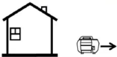
natural_image
Simple line drawing of a house and a printer icon (no text or symbols)AVERTISSEMENT DE SYSTÈME D'ÉCHAPPEMENT BRÛLANT
natural_image
Silhouette of a hand with fingers extended (no text or symbols)
CARACTÉRISTIQUES ET COMMANDES APERÇU
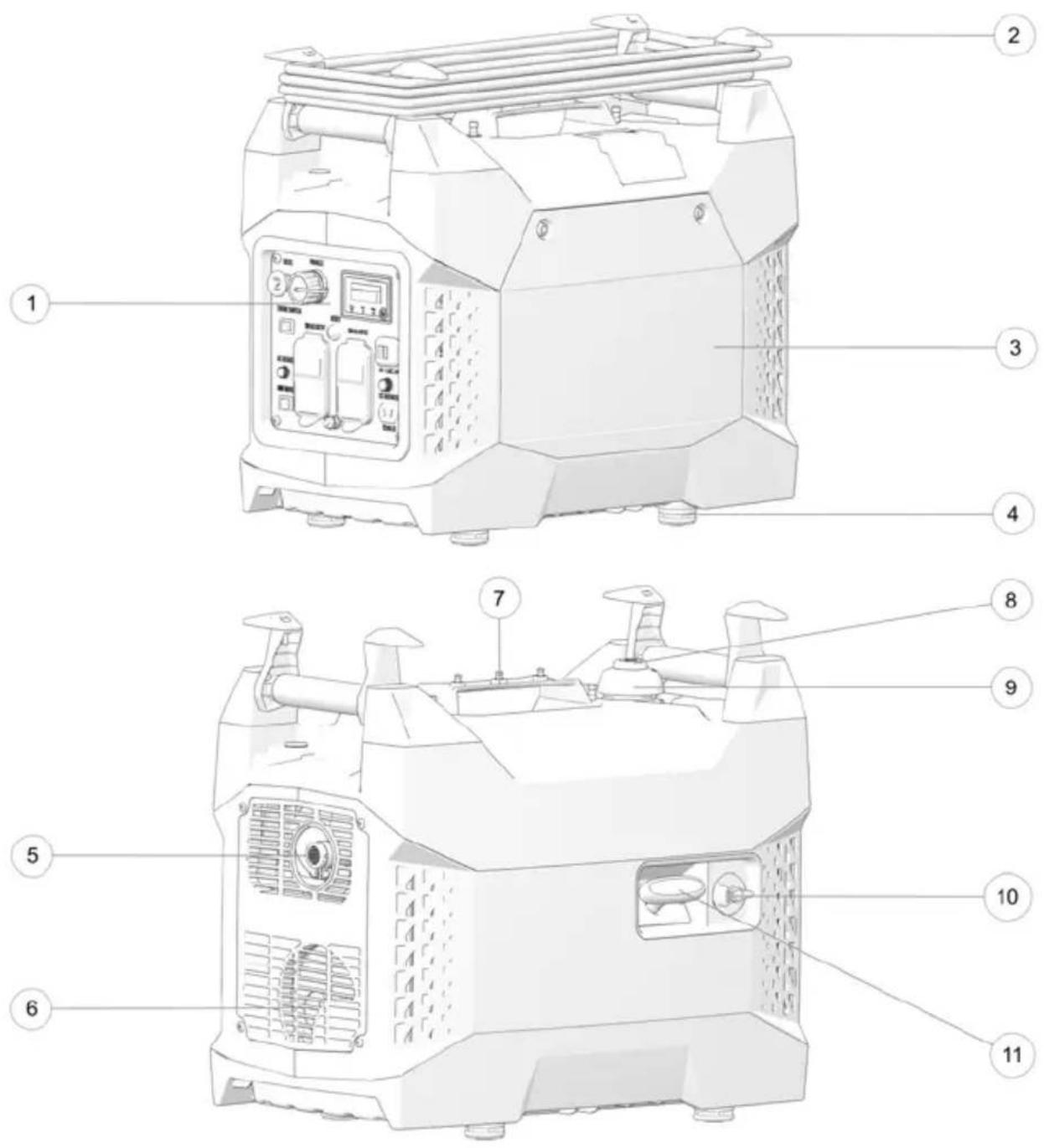
CARACTÉRISTIQUES ET COMMANDES
natural_image
Simple diagram with a rectangle containing a small crescent and a horizontal line, no text or symbols present.FENÊTRE DE TÉMOINS
natural_image
3D-rendered white octagonal object with two internal rectangular cutouts (no text or symbols)INTERRUPTEUR DE ROBINET DE CARBURANT
ATTENTION
natural_image
Diagram of a mechanical component with a yellow component and numbered label (1), no readable text or symbols present.AVIS
natural_image
3D rendering of a red spray bottle inserted into a white vehicle chassis (no text or symbols visible)natural_image
Illustration of a yellow object on a white surface with a numbered label (1) pointing to it, no text or symbols present.INSPECTION PRÉALABLE

AVERTISSEMENT
natural_image
Illustration of a yellow object on a white surface with a numbered label (1) pointing to it, no text or symbols present.DÉMARRAGE DU MOTEUR
! DANGER
natural_image
3D-rendered white geometric shape with two internal cutouts, no text or symbols present
ATTENTION
EXIGENCES RELATIVES AU SYSTÈME
natural_image
Black-and-white photo of four different electrical components: a funnel, coiled cable, clamp, and a cylindrical device (no text or symbols visible)natural_image
Illustration of a robotic arm with a yellow briefcase and mechanical components (no text or symbols visible)IMPORTANT
BOUGIE NORMALE
REPLACEMENT D'UNE BOUGIE
IMPORTANT
natural_image
Mechanical assembly diagram showing a yellow component inserted into a housing (no text or symbols visible)natural_image
Technical line drawing of a mechanical component with no visible text or symbols
AVERTISSEMENT
natural_image
Illustration of a yellow object on a mechanical device with a numbered label (1) pointing to it, no text or symbols present.STABILISATION DU CARBURANT

AVERTISSEMENT
natural_image
Technical illustration of a mechanical assembly with numbered components (no visible text or symbols)AUCUNE ALIMENTATION AU NIVEAU DES PRISES C.A.
GARANTIE ET EXCLUSIONS
LIMITATIONS DE GARANTIE ET RECOURS


- OWNER'S MANUAL
- WARNING
- FOR MAINTENANCE AND SAFETY
- P2000I
- INTRODUCTION
- OVERVIEW
- NOTICE
- INTENDED USE
- SAFETY SYMBOLS AND SIGNAL WORDS
- DANGER
- CAUTION
- IMPORTANT
- GENERATOR IDENTIFICATION NUMBERS
- SAFETY
- SAFETY WARNINGS
- OPERATOR SAFETY
- OPERATING WITHOUT INSTRUCTION
- FAILURE TO INSPECT BEFORE OPERATING
- USING ALCOHOL OR DRUGS
- CARBON MONOXIDE SAFETY
- ELECTRICAL SAFETY
- ! DANGER
- EXTENSION CORD USE
- CHOOSING A PROPER EXTENSION CORD
- EXTENSION CORD SAFETY
- FIRE SAFETY
- EXPOSURE TO EXHAUST
- HOT EXHAUST SYSTEMS
- RUNNING GENERATORS IN PARALLEL
- EQUIPMENT MODIFICATIONS
- HANDLING GASOLINE
- OPERATION RULES
- NOISE LEVEL
- HEARING PROTECTION
- SAFETY LABELS AND LOCATIONS
- GENERAL WARNING
- CARBON MONOXIDE WARNING
- HOT EXHAUST CAUTION
- FEATURES AND CONTROLS OVERVIEW
- PARALLEL SOCKET
- OVERLOAD RESET BUTTON
- CHOKE LEVER
- ENGINE SWITCH
- CIRCUIT BREAKERS
- SMART THROTTLE SWITCH
- SMART THROTTLE
- USB PORTS
- DC RECEPTACLE
- FUEL VALVE SWITCH
- FUEL TANK CAP VENT LEVER
- STARTER RECOIL GRIP
- GROUND TERMINAL
- AC RECEPTACLES
- FIRST USE INSTRUCTIONS
- ADDING ENGINE OIL
- FUEL
- FUEL RECOMMENDATION
- ADDING FUEL
- OPERATION
- SAFE OPERATING PRECAUTIONS
- REFUELING
- STARTING THE ENGINE
- STOPPING THE ENGINE
- AC OPERATION
- DC OPERATION
- BATTERY CHARGING
- CONNECTING THE BATTERY CHARGING CABLE
- DC CIRCUIT OVERLOAD
- DISCONNECTING THE BATTERY CHARGING CABLE
- AIR CONDITIONING OPERATION
- STANDBY POWER
- CONNECTIONS TO A BUILDING ELECTRICAL SYSTEM
- GROUND SYSTEM
- SYSTEM REQUIREMENTS
- HIGH ALTITUDE USE
- CARBURETOR MODIFICATION
- ALTITUDE KITS
- U.S. AND CALIFORNIA CLEAN AIR ACTS
- ALTERATIONS
- PROBLEMS AFFECTING EMISSIONS
- REPLACEMENT PARTS
- MAINTENANCE
- IMPORTANCE OF MAINTENANCE
- TOOL KIT
- MAINTENANCE SAFETY
- PERIODIC MAINTENANCE
- REMOVING THE MAINTENANCE COVER
- FUEL SYSTEM
- FUEL LINE INSPECTION
- GAS TANK STRAINER
- ENGINE OIL
- OIL RECOMMENDATION
- OIL LEVEL INSPECTION
- OIL CHANGE
- MEASUREMENT
- HIGH ALTITUDE JETS
- ALTITUDE JET SPECIFICATIONS
- JET INSTALLATION
- AIR FILTER
- FOAM FILTERS
- SPARK PLUG
- SPARK PLUG INSPECTION
- NORMAL PLUG
- WET FOULED PLUG
- SPARK PLUG REPLACEMENT
- SPARK ARRESTER
- REMOVING THE SPARK ARRESTER
- CLEANING AND STORAGE
- CLEANING THE GENERATOR
- STORAGE PREPARATION
- ACCESSING THE FUEL TANK
- STABILIZING THE FUEL
- DRAINING THE FUEL
- FOGGING THE ENGINE
- BATTERY STORAGE
- STORAGE PRECAUTIONS
- REMOVAL FROM STORAGE
- TRANSPORTING THE GENERATOR
- SPECIFICATIONS
- POLARIS PRODUCTS
- OIL AND LUBRICANTS
- TROUBLESHOOTING
- ENGINE WILL NOT TURN OVER
- ENGINE RUNS IRREGULARLY, STALLS OR MISFIRES
- LEAN FUEL
- RICH FUEL
- WARRANTY
- LIMITED WARRANTY
- REGISTRATION
- WARRANTY COVERAGE AND EXCLUSIONS LIMITATION OF WARRANTIES AND REMEDIES
- LUBRICANTS AND FLUIDS
- HOW TO OBTAIN WARRANTY SERVICE
- IN THE COUNTRY WHERE YOUR PRODUCT WAS PURCHASED:
- OUTSIDE THE COUNTRY WHERE YOUR PRODUCT WAS PURCHASED:
- IF YOU MOVE:
- IF YOU PURCHASE FROM A PRIVATE PARTY:
- EXPORTED PRODUCTS
- www.polaris.com/en-us/contact
- EMISSION CONTROL SYSTEM LIMITED WARRANTY
- YOUR WARRANTY RIGHTS AND OBLIGATIONS UNITED STATES & CANADA
- CALIFORNIA RESIDENTS
- OWNER'S WARRANTY RESPONSIBILITIES
- WARRANTY COVERAGE
- EXCLUSIONS
- TO OBTAIN WARRANTY SERVICE
- DISCLAIMER
- SPARK ARRESTOR LIMITED WARRANTY
- CONTACT INFORMATION
- MAINTENANCE LOG
- A
- B
- F
- C
- D
- E
- G
- H
- |
- L
- M
- N
- 0
- P
- R
- S
- T
- U
- V
- W
- AVERTISSEMENT
- ABSENCE D'INSPECTION AVANT LA CONDUITE
- ATTENTION
- MANUTENTION DE L'ESSENCE
- AVERTISSEMENT RELATIF AU MONOXYDE DE CARBONE
- AVERTISSEMENT DE SYSTÈME D'ÉCHAPPEMENT BRÛLANT
- CARACTÉRISTIQUES ET COMMANDES APERÇU
- INTERRUPTEUR DE ROBINET DE CARBURANT
- AVIS
- INSPECTION PRÉALABLE
- DÉMARRAGE DU MOTEUR
- EXIGENCES RELATIVES AU SYSTÈME
- BOUGIE NORMALE
- REPLACEMENT D'UNE BOUGIE
- STABILISATION DU CARBURANT
- AUCUNE ALIMENTATION AU NIVEAU DES PRISES C.A.
- GARANTIE ET EXCLUSIONS
- LIMITATIONS DE GARANTIE ET RECOURS
Brand : POLARIS
Model : P2000i (2020)
Category : Generator